JP2015191663A - Docking station having folding key board - Google Patents
Docking station having folding key board Download PDFInfo
- Publication number
- JP2015191663A JP2015191663A JP2015018852A JP2015018852A JP2015191663A JP 2015191663 A JP2015191663 A JP 2015191663A JP 2015018852 A JP2015018852 A JP 2015018852A JP 2015018852 A JP2015018852 A JP 2015018852A JP 2015191663 A JP2015191663 A JP 2015191663A
- Authority
- JP
- Japan
- Prior art keywords
- sub
- keyboard
- upper cover
- docking station
- positioning
- Prior art date
- Legal status (The legal status is an assumption and is not a legal conclusion. Google has not performed a legal analysis and makes no representation as to the accuracy of the status listed.)
- Granted
Links
Images


Landscapes
- Input From Keyboards Or The Like (AREA)
- Casings For Electric Apparatus (AREA)
Abstract
Description
本発明は、ドッキングステーションに関するものであり、特に、折りたたみ式キーボードを有するドッキングステーションに関するものである。 The present invention relates to a docking station, and more particularly to a docking station having a folding keyboard.
現代の電子製品は常に進化しており、中でも、タブレットPC(tablet PC)やスマートフォン(smart phone)といった携帯に便利でメッセージの送受信を即時に行える携帯型電子デバイスが消費者に広く普及している。 Modern electronic products are constantly evolving. Among them, portable electronic devices such as tablet PCs and smart phones that are convenient to carry and can send and receive messages instantly are widely used by consumers. .
携帯型電子デバイスは携帯に便利という利点を有するが、使用者が手で持って固定しなければならないため、長時間持ち続ける場合には、使用者にとって不便である。また、現在の携帯型電子デバイスの多くは、タッチパネルを入力インターフェースとして使用しているが、タッチ入力方式は、実際の打鍵感を使用者に与えることができないため、打鍵感を有する実体のキーボードを携帯型電子デバイスに取り付ける必要が依然としてある。 Although the portable electronic device has an advantage of being convenient for carrying, it is inconvenient for the user to keep it for a long time because the user must hold it by hand and fix it. In addition, many of the current portable electronic devices use a touch panel as an input interface. However, since the touch input method cannot give an actual keystroke feeling to the user, an actual keyboard having a keystroke feeling is used. There remains a need to attach to portable electronic devices.
上述した問題を改善するため、現有の技術は、キーボードを有するドッキングステーションを開発している。しかし、現有の技術は、ドッキングステーションの体積を減らすために、通常、ドッキングステーションの中に折りたたみ式キーボードを配置しているため、使用者がキーボードを使用する時は、キーボードを手動で組み立てなければならない。また、ドッキングステーションは、通常、支持フレームを取り付けることによって携帯型電子デバイスのスクリーンとキーボードの間の視角を調整するため、使用者が視角を変更する時は、支持フレームの位置を手動で調整しなければならない。しかしながら、上述したドッキングステーションは、使用者がキーボードを使用する必要があるかどうか、または視角を調整する必要があるかどうかに関わらず、いずれもこれらの作業を手動で別々に行う必要があるため、使用者にとって不便である。 In order to ameliorate the above-mentioned problems, existing technologies are developing docking stations with keyboards. However, current technology usually places a folding keyboard inside the docking station to reduce the volume of the docking station, so the user must assemble the keyboard manually when using the keyboard. Don't be. In addition, since the docking station usually adjusts the viewing angle between the screen of the portable electronic device and the keyboard by attaching a supporting frame, when the user changes the viewing angle, the position of the supporting frame is manually adjusted. There must be. However, the docking stations described above all need to perform these tasks manually, regardless of whether the user needs to use the keyboard or whether the viewing angle needs to be adjusted. Inconvenient for the user.
本発明は、優れた操作便利性を有する折りたたみ式キーボードを有するドッキングステーションを提供する。 The present invention provides a docking station having a foldable keyboard with excellent operational convenience.
本発明は、携帯型電子デバイスをドッキングするための折りたたみ式キーボードを有するドッキングステーションを提供する。折りたたみ式キーボードを有するドッキングステーションは、上カバーと、ベースと、支持部材と、スライドアセンブリと、2つのサブキーボードとを含む。上カバーは、携帯型電子デバイスを支持するために用いられる。ベースは、シュートおよび2つのL型ガイド溝を有する。シュートは、2つのL型ガイド溝の間に配置され、各L型ガイド溝は、第1ガイド部、屈折点および第2ガイド部を有し、屈折点は、第1ガイド部と第2ガイド部を連接する。支持部材の一端は、上カバーに枢接され、他端は、ベースに枢接される。スライドアセンブリは、シュートにスライド可能に配置され、上カバーに枢接される。各サブキーボードは、対応するL型ガイド溝にスライド可能に配置され、スライドアセンブリに枢接される。上カバーがスライドアセンブリを介してベースに相対して回動した時、スライドアセンブリを連動させてベースに相対してスライドし、2つのサブキーボードを連動させる。各サブキーボードが第1ガイド部に沿って屈折点にスライドした時、2つのサブキーボードが回動して完全なキーボードに組み立てられ、支持部材が上カバーを支持するため、各サブキーボードが屈折点から第2ガイド部に沿ってスライドした時に、上カバーと完全なキーボードの間の角度を変更することができる。 The present invention provides a docking station having a folding keyboard for docking a portable electronic device. A docking station having a foldable keyboard includes an upper cover, a base, a support member, a slide assembly, and two sub-keyboards. The top cover is used to support the portable electronic device. The base has a chute and two L-shaped guide grooves. The chute is disposed between two L-shaped guide grooves, and each L-shaped guide groove has a first guide portion, a refraction point, and a second guide portion, and the refraction point is defined by the first guide portion and the second guide. Concatenate parts. One end of the support member is pivoted to the upper cover, and the other end is pivoted to the base. The slide assembly is slidably disposed on the chute and is pivotally connected to the upper cover. Each sub-keyboard is slidably disposed in a corresponding L-shaped guide groove and is pivotally connected to the slide assembly. When the upper cover is rotated relative to the base via the slide assembly, the slide assembly is interlocked to slide relative to the base, and the two sub-keyboards are interlocked. When each sub-keyboard slides along the first guide portion to the refraction point, the two sub-keyboards rotate and are assembled into a complete keyboard, and the support member supports the upper cover. When sliding along the second guide portion, the angle between the upper cover and the complete keyboard can be changed.
本発明の1つの実施形態において、上述した各L型ガイド溝の第2ガイド部は、シュートに平行である。 In one embodiment of the present invention, the second guide portion of each L-shaped guide groove described above is parallel to the chute.
本発明の1つの実施形態において、上述した2つのL型ガイド溝は、シュートを対称線として対称配置される。 In one embodiment of the present invention, the two L-shaped guide grooves described above are arranged symmetrically with the chute as a symmetry line.
本発明の1つの実施形態において、上述した各L型ガイド溝において、屈折点における回転角は、直角である。 In one embodiment of the present invention, in each of the L-shaped guide grooves described above, the rotation angle at the refraction point is a right angle.
本発明の1つの実施形態において、上述した各L型ガイド溝の第1ガイド部は、起点および中間点を有し、起点は、中間点と屈折点の間に位置し、上カバーがスライドアセンブリを連動させてベースに相対してスライドし、各サブキーボードを連動させた時、各サブキーボードは、起点から中間点を通過して屈折点にスライドする。 In one embodiment of the present invention, the first guide portion of each L-shaped guide groove described above has a starting point and an intermediate point, the starting point is located between the intermediate point and the refraction point, and the upper cover is a slide assembly. When the sub-keyboards are slid relative to the base in conjunction with each other and the sub-keyboards are linked, the sub-keyboards slide from the starting point through the intermediate point to the refraction point.
本発明の1つの実施形態において、上述したスライドアセンブリは、スライド軸と、枢接部材とを含む。スライド軸は、シュートにスライド可能に配置される。枢接部材の一端は、上カバーに枢接し、他端は、スライド軸に連接する。 In one embodiment of the present invention, the slide assembly described above includes a slide shaft and a pivot member. The slide shaft is slidably disposed on the chute. One end of the pivot member is pivoted to the upper cover, and the other end is linked to the slide shaft.
本発明の1つの実施形態において、上述した各サブキーボードは、複数の位置決め部を有し、ドッキングステーションは、さらに、2つの位置決めアセンブリを含む。2つの位置決めアセンブリは、ベースに固設され、それぞれ2つのサブキーボードに対応する。各位置決めアセンブリは、対応する位置決め部に選択的に係合され、各サブキーボードをベースに固定させることができる。 In one embodiment of the present invention, each sub-keyboard described above has a plurality of positioning portions, and the docking station further includes two positioning assemblies. The two positioning assemblies are fixed to the base and each correspond to two sub-keyboards. Each positioning assembly can be selectively engaged with a corresponding positioning portion to secure each sub-keyboard to the base.
本発明の1つの実施形態において、上述した複数の位置決め部は、位置決め孔であり、各位置決めアセンブリは、位置決め柱と、弾性部材とを含む。弾性部材は、位置決め柱に套設され、位置決め柱は、弾性部材の弾力により、対応する位置決め孔の中に係合される。 In one embodiment of the present invention, the plurality of positioning portions described above are positioning holes, and each positioning assembly includes a positioning post and an elastic member. The elastic member is provided on the positioning column, and the positioning column is engaged with the corresponding positioning hole by the elastic force of the elastic member.
本発明の1つの実施形態において、上述した各サブキーボードは、突出部を有する。各サブキーボードは、対応する突出部を介して、対応するL型ガイド溝にスライド可能に配置される。 In one embodiment of the present invention, each sub-keyboard described above has a protrusion. Each sub-keyboard is slidably disposed in a corresponding L-shaped guide groove via a corresponding protrusion.
以上のように、本発明の実施形態のドッキングステーションは、スライドアセンブリが上カバーと2つのサブキーボードを連接しているため、2つのサブキーボードと上カバーを連動させることができる。そのため、使用者が上カバーをベースに相対して回動起立させた時、同時に、2つのサブキーボードを連動させて、完全なキーボードに組み立てることができる。さらに、2つのサブキーボードを完全なキーボードに組み立てた後、使用者は、上カバーを引き続きベースに相対して回動起立させることができるため、各サブキーボードを引き続き対応するL型ガイド溝でスライドさせて、上カバーと完全なキーボードの間の角度を変更することができ、これにより、快適な視角を得ることができる。上述した操作過程において、支持部材は、上カバーとベースの間を支持して、上カバーを安定して起立させるため、使用者は、上カバーを移動させるだけで他の部材を連動させることができ、操作過程を簡単にすることができる。したがって、本発明のドッキングステーションは、優れた操作便利性を有する。 As described above, in the docking station according to the embodiment of the present invention, since the slide assembly connects the upper cover and the two sub keyboards, the two sub keyboards and the upper cover can be interlocked. Therefore, when the user raises the upper cover relative to the base, the two sub-keyboards can be simultaneously linked to assemble the complete keyboard. In addition, after assembling the two sub-keyboards into a complete keyboard, the user can continue to pivot the upper cover relative to the base so that each sub-keyboard continues to slide in the corresponding L-shaped guide groove. Thus, the angle between the top cover and the complete keyboard can be changed, thereby providing a comfortable viewing angle. In the above-described operation process, the support member supports the space between the upper cover and the base and stably stands the upper cover. Therefore, the user can move the upper cover to move other members together. And the operation process can be simplified. Therefore, the docking station of the present invention has excellent operational convenience.
本発明の上記および他の目的、特徴、および利点をより分かり易くするため、図面と併せた幾つかの実施形態を以下に説明する。 In order to make the above and other objects, features and advantages of the present invention more comprehensible, several embodiments accompanied with figures are described below.
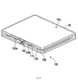
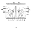
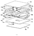
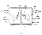
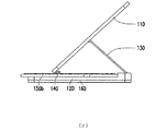
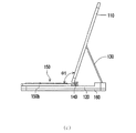
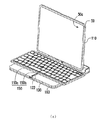
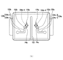
図1(a)は、本発明の1つの実施形態に係る折りたたみ式キーボードを有するドッキングステーションの概略的斜視図である。図1(b)は、図1(a)のドッキングステーションの概略的底面図である。図1(c)は、図1(a)のドッキングステーションの別の視角の概略的展開図である。ここで、説明すべきこととして、図面を明確にするため、以下の概略的底面図は、一部の部材を省略してある。図1(a)〜図1(c)を同時に参照すると、本実施形態の折りたたみ式キーボードを有するドッキングステーション100は、タブレットPCやスマートフォン等の携帯型電子デバイス50を支持するために用いられ、使用者は、携帯している携帯型電子デバイス50をドッキングステーション100にドッキングさせることによって、長時間持ち続けた時の不快感を回避することができる。
FIG. 1 (a) is a schematic perspective view of a docking station having a folding keyboard according to one embodiment of the present invention. FIG. 1 (b) is a schematic bottom view of the docking station of FIG. 1 (a). FIG. 1 (c) is a schematic development view of another viewing angle of the docking station of FIG. 1 (a). Here, as a matter of explanation, in order to clarify the drawing, some members are omitted from the following schematic bottom view. Referring to FIGS. 1A to 1C at the same time, the
ドッキングステーション100は、上カバー110と、ベース120と、支持部材130と、スライドアセンブリ140と、サブキーボード150aと、サブキーボード150bと、下カバー160とを含む。ベース120は、シュート122、L型ガイド溝124aおよびL型ガイド溝124bを有する。シュート122は、L型ガイド溝124aとL型ガイド溝124bの間に配置される。支持部材130の一端は、上カバー110に枢接され、他端は、ベース120に枢接される。スライドアセンブリ140は、シュート122にスライド可能に配置され、上カバー110に枢接される。サブキーボード150aは、L型ガイド溝124aにスライド可能に配置され、サブキーボード150bは、L型ガイド溝124bにスライド可能に配置される。サブキーボード150aおよびサブキーボード150bは、スライドアセンブリ140に枢接される。下カバー160は、ベース120を覆い、携帯型電子デバイス50の底部全体を保護する。図1(a)の概略的斜視図は、上カバー110が携帯型電子デバイス50を支持し、且つベース120に相対して閉じられている状態を示したものであり、携帯型電子デバイス50の表示面50aを上カバー110に露出させ、この時、サブキーボード150aとサブキーボード150bを上カバー110とベース120の間に収納することによって、ドッキングステーション100の全体の体積を効果的に縮小することができる。
The
図1(a)の状態において、使用者は、例えば、タッチ方式で携帯型電子デバイス50を操作することができる。使用者が入力インターフェースをキーボードに変更する必要がある場合、上カバー110をベース120に相対して回動起立させることにより、サブキーボード150aとサブキーボード150bを連動させて、完全なキーボード150に組み立てることができる(図3(a)に示す)。本実施形態において、スライドアセンブリ140は、上カバー110、サブキーボード150aおよびサブキーボード150bを連接しているため、上カバー110、サブキーボード150aおよびサブキーボード150bは、連動関係を有する。具体的に説明すると、上カバー110がベース120に相対して閉じられている状態(図1(a)に示す)から、スライドアセンブリ140を介してベース120に相対して回動起立する状態に変更した時、上カバー110は、スライドアセンブリ140をベース120のシュート122に相対してスライドさせ、同時に、サブキーボード150aとサブキーボード150bを連動させて、それぞれL型ガイド溝124aおよびL型ガイド溝124bにスライドさせるため、完全なキーボード150に組み立てられる(図3(a)に示す)。注意すべきこととして、上カバー110がベース120に相対して回動起立する過程において、支持部材130は、上カバー110を支持して、上カバー110を安定して起立させるため、上カバー110が携帯型電子デバイス50を収納した後に重すぎて倒れるのを防ぐことができる。
In the state of FIG. 1A, the user can operate the portable
このように、上カバー110がベース120に相対して回動起立すると同時に、サブキーボード150aとサブキーボード150bを完全なキーボード150に組み立てることができるため、使用者の操作手順が簡易化される。さらに、サブキーボード150aとサブキーボード150bを完全なキーボード150に組み立てた後、上カバー110は、引き続きベース120に相対して回動することができるため、スライドアセンブリ140がシュート122においてスライドすることによって、サブキーボード150aとサブキーボード150bをそれぞれL型ガイド溝124aとL型ガイド溝124bに引き続きスライドさせることができる。この時、上カバー110と完全なキーボード150の間の角度を変更することにより(図4(a)に示す)、表示面50aの視角を調整することができる。つまり、本実施形態は、サブキーボード150aとサブキーボード150bを完全なキーボード150に組み立てた後、さらに上カバー110と完全なキーボード150の間の角度を変更することもできる。
As described above, since the
本実施形態において、サブキーボード150aは、突出部152aを有し、サブキーボード150bは、突出部152bを有する。サブキーボード150aは、突出部152aを介してL型ガイド溝124aにスライド可能に配置され、サブキーボード150bは、突出部152bを介してL型ガイド溝124bにスライド可能に配置される。L型ガイド溝124aおよびL型ガイド溝124bは、シュート122を対称線として対称配置される。L型ガイド溝124aは、第1ガイド部124a‐1、屈折点P3aおよび第2ガイド部124a‐2を有し、屈折点P3aは、第1ガイド部124a‐1および第2ガイド部124a‐2を連接する。L型ガイド溝124aは、さらに、起点P1a、中間点P2aおよび終点P4aを有し、起点P1aおよび中間点P2aは、第1ガイド部124a‐1に配置され、終点P4aは、第2ガイド部124a‐2に配置される。サブキーボード150aを図1(a)のように上カバー110とベース120の間に収納した時、突出部152aは、起点P1aに配置され、図1(b)の破線で示したように、突出部152aは、中間点P2a、屈折点P3aおよび終点P4aに配置される。屈折点P3aは、起点P1aと終点P4aの間に配置され、第1ガイド部124a‐1と第2ガイド部124a‐2を連接し、起点P1aは、中間点P2aと屈折点P3aの間に配置される。第2ガイド部124a‐2は、シュート122に平行である。L型ガイド溝124aにおいて、屈折点P3aの回転角φaは直角であるが、別の実施形態において、回転角φaの角度は、ドッキングステーション100の大きさに応じて任意に調整してもよい。
In the present embodiment, the
同様にして、L型ガイド溝124bは、第1ガイド部124b‐1、屈折点P3b、第2ガイド部124b‐2、起点P1b、中間点P2bおよび終点P4bを有し、サブキーボード150bを図1(a)のようにカバー110とベース120の間に収納した時、突出部152bは、起点P1aに配置される。屈折点P3bは、起点P1bと終点P4bの間に配置され、第1ガイド部124b‐1と第2ガイド部124b‐2を連接し、起点P1bは、中間点P2bと屈折点P3bの間に配置される。説明すべきこととして、本実施形態のL型ガイド溝124aとL型ガイド溝124bは対称配置であることから、L型ガイド溝124bの第1ガイド部124b‐1、屈折点P3b、第2ガイド部124b‐2、起点P1b、中間点P2bおよび終点P4bの配置および回転角φbの角度は、L型ガイド溝124aの説明を参照することができるため、ここでは繰り返し説明しない。
Similarly, the L-shaped
上カバー110がスライドアセンブリ140を連動させてベース120に相対してスライドし、サブキーボード150aとサブキーボード150bを連動させた時、サブキーボード150aの突出部152aがL型ガイド溝124aの位置にあり、サブキーボード150bの突出部152bがL型ガイド溝124bの位置にあることから、サブキーボード150aとサブキーボード150bの運動過程を2つの部分に分けることができる。サブキーボード150aを例にして説明すると、第1部分は、突出部152aが第1ガイド部124a‐1に沿って屈折点P3aにスライドする部分である。この時、突出部152aは、起点P1aから中間点P2aを通過して屈折点P3aにスライドし、サブキーボード150aがスライドすると同時にサブキーボード150bも回動して、完全なキーボード150に組み立てられる。第2部分は、突出部152aが屈折点P3aから第2ガイド部124a‐2に沿ってスライドすることのできる部分である。この時、突出部152aは、屈折点P3aと終点P4aの間でスライドし、サブキーボード150aとサブキーボード150bは、既に完全なキーボード150に組み立てられ、組み立てられた状態を維持する。第2部分の運動過程において、上カバー110の完全なキーボード150に相対する角度は変化する。同様に、サブキーボード150bのL型ガイド溝124bにおける運動過程も、2つの部分に分けることができるが、この部分は、サブキーボード150aと同じであるため、ここでは説明を省略する。
When the
本実施形態において、スライドアセンブリ140は、スライド軸142と、枢接部材144とを含む。スライド軸142は、シュート122にスライド可能に配置される。枢接部材144の一端は、上カバー110に枢接し、他端は、スライド軸142に連接する。本実施形態において、サブキーボード150aとサブキーボード150bは、スライド軸142に套設され、上述した第1部分の運動過程において、スライド軸142に相対して回動する。サブキーボード150aは、複数の位置決め部154a‐1、154a‐2、154a‐3および154a‐4を有し、サブキーボード150bは、複数の位置決め部154b‐1、154b‐2、154b‐3および154b‐4を有する。位置決め部154a‐1〜154b‐4は、例えば、位置決め孔である。
In the present embodiment, the
ドッキングステーション100は、さらに、位置決めアセンブリ170aと位置決めアセンブリ170bを含む。位置決めアセンブリ170aと位置決めアセンブリ170bは、例えば、係止部材によりベース120の底部に固設され、下カバー160とベース120の間に配置される。位置決めアセンブリ170aは、サブキーボード150aに対応して設置され、位置決めアセンブリ170bは、サブキーボード150bに対応して設置される。詳しく説明すると、位置決めアセンブリ170aは、位置決め柱172aと、バネ等の弾性部材174aとを含む。同様に、位置決めアセンブリ170bは、位置決め柱172bと、バ弾性部材174bとを含む。弾性部材174aは、位置決め柱172aに套設され、弾性部材174bは、位置決め柱172bに套設される。
位置決めアセンブリ170aは、対応する位置決め部154a‐1、154a‐2、154a‐3および154a‐4に選択的に係合され、位置決めアセンブリ170bは、対応する位置決め部154b‐1、154b‐2、154b‐3および154b‐4に選択的に係合される。詳しく説明すると、サブキーボード150aとサブキーボード150bを上カバー110とベース120の間に収納した時(図1(a)に示す)、あるいは、サブキーボード150aとサブキーボード150bを完全なキーボード150に組み立てた時(図3(a)および図4(a)に示す)、位置決めアセンブリ170aは、位置決め部154a‐1、154a‐2、154a‐3および154a‐4のうちの1つに係合され、位置決めアセンブリ170bは、位置決め部154b‐1、154b‐2、154b‐3および154b‐4のうちの1つに係合される。例を挙げて説明すると、図1(b)に示すように、位置決めアセンブリ170aと位置決めアセンブリ170bは、突出部152aが起点P1aにあり、突出部152bが起点P1bにある時、それぞれ位置決め部154a‐1と位置決め部154b‐1に係合されるため、サブキーボード150aとサブキーボード150bをベース120に固定することができる。
The
以下、図面を参照しながら、ドッキングステーション100の上カバー110がサブキーボード150aとサブキーボード150bを連動させて完全なキーボード150に組み立てるプロセス、さらに、完全なキーボード150と上カバー110の間の角度を変更するプロセスについて説明する。
Hereinafter, referring to the drawings, the process in which the
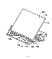
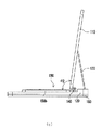
図2(a)は、サブキーボードが中間点にある時のドッキングステーションの概略的斜視図である。図2(b)は、図2(a)のドッキングステーションの概略的底面図である。図2(c)は、図2(a)のドッキングステーションの概略的側面図である。図2(a)〜図2(c)を同時に参照すると、上カバー110が図1(a)の状態からベース120に相対して図2(a)の状態に回動起立した時、上カバー110は、スライドアセンブリ140を連動させてベース120に相対してスライドし、サブキーボード150aとサブキーボード150bを連動させるため、サブキーボード150aの突出部152aが第1ガイド部124a‐1に沿ってスライドして、図1(b)の起点P1aから図2(b)の中間点P2aにスライドする。同様に、サブキーボード150bの突出部152bは、第1ガイド部124b‐1に沿ってスライドして、図1(b)の起点P1bから図2(b)の中間点P2bにスライドする。この時、サブキーボード150aとサブキーボード150bが同時に回動して、支持部材130が上カバー110とベース120の間を支持するため、携帯型電子デバイス50を安定して起立させることができる。注意すべきこととして、この状態において、突出部152aと突出部152bは、互いに離れている。
FIG. 2A is a schematic perspective view of the docking station when the sub-keyboard is at an intermediate point. FIG. 2 (b) is a schematic bottom view of the docking station of FIG. 2 (a). FIG. 2 (c) is a schematic side view of the docking station of FIG. 2 (a). Referring to FIGS. 2 (a) to 2 (c) simultaneously, when the
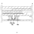
図2(d)は、図2(b)における線AA’に沿った概略的断面図である。サブキーボード150aが中間点P2aにスライドした時、サブキーボード150aは、位置決めアセンブリ170aを押し出す。具体的に説明すると、サブキーボード150aは、対応する位置決め柱172aを押し出すため、位置決め柱172aは、弾性部材174aを沈下させて圧縮する。同様に、サブキーボード150bは、位置決めアセンブリ170bを押し出す。これにより、位置決めアセンブリ170aは、図1(b)に示した位置決め部154a‐1を離脱し、位置決めアセンブリ170bは、図1(b)に示した位置決め部154b‐1を離脱することができる。
FIG. 2D is a schematic cross-sectional view along the line AA ′ in FIG. When the
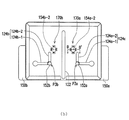
図3(a)は、サブキーボードが屈折点にある時のドッキングステーションの概略的斜視図である。図3(b)は、図3(a)のドッキングステーションの概略的底面図である。図3(c)は、図3(a)のドッキングステーションの概略的側面図である。図3(a)〜図3(c)を同時に参照すると、上カバー110が図2(a)の位置からベース120に相対して図3(a)の状態に回動起立した時、サブキーボード150aの突出部152aは、第1ガイド部124a‐1に沿ってスライドして、図2(b)の中間点P2aから図3(b)の屈折点P3aにスライドする。同様に、サブキーボード150bの突出部152bは、第1ガイド部124b‐1に沿ってスライドして、図2(b)の中間点P2bから図3(b)の屈折点P3bにスライドする。この時、サブキーボード150aとサブキーボード150bは、完全なキーボード150に組み立てられ、上カバー110と完全なキーボード150の間の角度は、θ1である。この状態において、使用者は、完全なキーボード150を入力インターフェースとして使用して、文書操作等を行うことができる。注意すべきこととして、この状態において、突出部152aと突出部152bは、互いに近づいている。
FIG. 3A is a schematic perspective view of the docking station when the sub keyboard is at the refraction point. FIG. 3B is a schematic bottom view of the docking station of FIG. FIG. 3 (c) is a schematic side view of the docking station of FIG. 3 (a). Referring to FIGS. 3A to 3C at the same time, when the
図3(d)は、図3(b)における線BB’に沿った概略的断面図である。サブキーボード150aとサブキーボード150bが完全なキーボード150に組み立てられた時、位置決めアセンブリ170aは、サブキーボード150aの位置決め部154a‐2に係合され、位置決めアセンブリ170bは、サブキーボード150bの位置決め部154b‐2に係合される。図3(d)に示した位置決めアセンブリ170aを例に挙げると、位置決め柱172aは、弾性部材174aの弾力によって上昇し、サブキーボード150aの位置決め部154a‐2内に係合される。これにより、完全なキーボード150をベース120に固定することができる。
FIG. 3D is a schematic cross-sectional view taken along line BB ′ in FIG. When the
図4(a)は、サブキーボードが終点にある時のドッキングステーションの概略的斜視図である。図4(b)は、図4(a)のドッキングステーションの概略的底面図である。図4(c)は、図4(a)のドッキングステーションの概略的側面図である。サブキーボード150aとサブキーボード150bが完全なキーボード150に組み立てられた後、使用者が携帯型電子デバイス50の表示面50aの傾斜角を調整する必要がある場合、上カバー110を図3(a)の位置から引き続きベース120に相対して図4(a)の状態に回動起立させることにより、サブキーボード150aの突出部152aは、図3(b)の屈折点P3aから第2ガイド部124a‐2に沿って図4(b)の終点P4aにスライドする。同様に、サブキーボード150bの突出部152bは、図3(b)の屈折点P3bから第2ガイド部124b‐2に沿って図4(b)の終点P4bにスライドする。この時、上カバー110と完全なキーボード150の間の角度は、θ2に変わる。
FIG. 4A is a schematic perspective view of the docking station when the sub keyboard is at the end point. FIG. 4B is a schematic bottom view of the docking station of FIG. FIG. 4 (c) is a schematic side view of the docking station of FIG. 4 (a). When the user needs to adjust the tilt angle of the
この時、位置決めアセンブリ170aおよび170bは、それぞれ対応する位置決め部154a‐4および154b‐4内に係合されるため、完全なキーボード150をベース120に相対して固定させることができる。説明すべきこととして、サブキーボード150aは、屈折点P3aと終点P4aの間の任意の位置でスライドすることができ、サブキーボード150bは、屈折点P3bと終点P4bの間の任意の位置でスライドすることができるため、完全なキーボード150と上カバー110の間の角度をθ1とθ2の間で調整することができ、さらに、位置決めアセンブリ170aと位置決めアセンブリ170bを介して完全なキーボード150を固定することができる。例えば、位置決めアセンブリ170aが図1(c)の位置決め部154a‐3に係合され、位置決めアセンブリ170bが図1(c)の位置決め部154b‐3に係合されている時、完全なキーボード150と上カバー110の間の角度は、θ1とθ2の間である。もちろん、本発明は位置決め部の数を限定しないため、位置決め部の数は、上カバー110と完全なキーボード150の間の調整可能な角度の数に基づいて変更可能である。
At this time, the
使用者が完全なキーボード150を使用する必要がない時、上述した図2(a)〜図4(a)のステップを逆に操作するだけで、完全なキーボード150をサブキーボード150aとサブキーボード150bに分解して、上カバー110とベース120の間に収納することができる。
When the user does not need to use the
以上のように、本発明の実施形態のドッキングステーションは、スライドアセンブリが上カバーと2つのサブキーボードを連接しているため、2つのサブキーボードと上カバーを連動させることができる。そのため、使用者が上カバーをベースに相対して回動起立させた時、同時に、2つのサブキーボードを連動させて完全なキーボードに組み立てることができる。さらに、2つのサブキーボードを完全なキーボードに組み立てた後、使用者は、上カバーを引き続きベースに相対して回動起立させることができるため、各サブキーボードを引き続き対応するL型ガイド溝でスライドさせて、上カバーと完全なキーボードの間の角度を変えることができ、これにより、快適な視角を得ることができる。上述した操作過程において、支持部材は、上カバーとベースの間を支持して、上カバーを安定して起立させるため、使用者は、上カバーを移動させるだけで他の部材を連動させることができ、操作過程を簡単にすることができる。したがって、本発明のドッキングステーションは、優れた操作便利性を有する。 As described above, in the docking station according to the embodiment of the present invention, since the slide assembly connects the upper cover and the two sub keyboards, the two sub keyboards and the upper cover can be interlocked. Therefore, when the user raises the upper cover relative to the base, the two sub-keyboards can be linked together to assemble a complete keyboard. In addition, after assembling the two sub-keyboards into a complete keyboard, the user can continue to pivot the upper cover relative to the base so that each sub-keyboard continues to slide in the corresponding L-shaped guide groove. Thus, the angle between the top cover and the complete keyboard can be changed, thereby providing a comfortable viewing angle. In the above-described operation process, the support member supports the space between the upper cover and the base and stably stands the upper cover. Therefore, the user can move the upper cover to move other members together. And the operation process can be simplified. Therefore, the docking station of the present invention has excellent operational convenience.
さらに、使用者が上カバーと完全なキーボードの間の角度を調整した時、ドッキングステーションの位置決めアセンブリが対応するサブキーボードの位置決め部に係合されるため、各サブキーボードをベースに固定することができる。位置決め部の数は、上カバーと完全なキーボードの間の調整可能な角度の数に基づいて変更可能であるため、本発明の実施形態のドッキングステーションは、優れた設計弾性を有する。 Furthermore, when the user adjusts the angle between the top cover and the complete keyboard, the docking station positioning assembly is engaged with the corresponding sub-keyboard positioning so that each sub-keyboard can be secured to the base. it can. Since the number of positioning parts can be changed based on the number of adjustable angles between the top cover and the complete keyboard, the docking station of the embodiment of the present invention has excellent design elasticity.
以上のごとく、この発明を実施形態により開示したが、もとより、この発明を限定するためのものではなく、当業者であれば容易に理解できるように、この発明の技術思想の範囲内において、適当な変更ならびに修正が当然なされうるものであるから、その特許権保護の範囲は、特許請求の範囲および、それと均等な領域を基準として定めなければならない。 As described above, the present invention has been disclosed by the embodiments. However, the present invention is not intended to limit the present invention, and is within the scope of the technical idea of the present invention so that those skilled in the art can easily understand. Therefore, the scope of patent protection should be defined based on the scope of claims and the equivalent area.
50 携帯型電子デバイス
50a 表示面
100 ドッキングステーション
110 上カバー
120 ベース
122 シュート
124a、124b L型ガイド溝
124a‐1、124b‐1 第1ガイド部
124a‐2、124b‐2 第2ガイド部
130 支持部材
140 スライドアセンブリ
142 スライド軸
144 枢接部材
150 完全なキーボード
150a、150b サブキーボード
152a、152b 突出部
154a‐1、154a‐2、154a‐3、154a‐4、154b‐1、154b‐2、154b‐3、154b‐4 位置決め部
160 下カバー
170a、170b 位置決めアセンブリ
172a、172b 位置決め柱
174a、174b 弾性部材
P1a、P1b 起点
P2a、P2b 中間点
P3a、P3b 屈折点
P4a、P4b 終点
φa、φb 回転角
θ1、θ2 角度
50 Portable
Claims (9)
前記携帯型電子デバイスを配置するため上カバーと、
第1ガイド部、第2ガイド部および前記第1ガイド部と前記第2ガイド部を連接する屈折点をそれぞれ有する2つのL型ガイド溝と、前記2つのL型ガイド溝の間に配置されたシュートとを有するベースと、
一端が前記上カバーに枢接され、他端が前記ベースに枢接された支持部材と、
前記シュートにスライド可能に配置され、前記上カバーに枢接されたスライドアセンブリと、
対応する前記L型ガイド溝にスライド可能に配置され、前記スライドアセンブリに枢接された2つのサブキーボードと
を含み、前記上カバーが前記スライドアセンブリを介して前記ベースに相対して回動した時、前記スライドアセンブリを連動させて前記ベースに相対してスライドし、前記2つのサブキーボードを連動させ、各前記サブキーボードが前記第1ガイド部に沿って前記屈折点にスライドした時、前記2つのサブキーボードが回動して完全なキーボードに組み立てられ、前記支持部材が前記上カバーを支持するため、各前記サブキーボードが前記屈折点から前記第2ガイド部に沿ってスライドした時に、前記上カバーと前記完全なキーボードの間の角度を変更することができる折りたたみ式キーボードを有するドッキングステーション。 A docking station having a folding keyboard for supporting a portable electronic device,
An upper cover for placing the portable electronic device;
The first guide portion, the second guide portion, and two L-type guide grooves each having a refraction point connecting the first guide portion and the second guide portion, and the two L-type guide grooves are disposed. A base having a chute,
A support member having one end pivoted to the upper cover and the other end pivoted to the base;
A slide assembly slidably disposed on the chute and pivotally connected to the upper cover;
Two sub-keyboards slidably disposed in the corresponding L-shaped guide grooves and pivotally connected to the slide assembly, and when the upper cover is rotated relative to the base via the slide assembly The slide assembly is slid relative to the base, the two sub-keyboards are interlocked, and each of the sub-keyboards is slid to the refraction point along the first guide portion. The sub keyboard is rotated to be assembled into a complete keyboard, and the support member supports the upper cover. Therefore, when the sub keyboard slides along the second guide portion from the refraction point, the upper cover is supported. Docking stasis with a folding keyboard that can change the angle between the complete keyboard and N
前記シュートにスライド可能に配置されたスライド軸と、
一端が前記上カバーに枢接し、他端が前記スライド軸に連接された枢接部材と
を含む請求項1に記載の折りたたみ式キーボードを有するドッキングステーション。 The slide assembly comprises:
A slide shaft slidably disposed on the chute;
The docking station having a foldable keyboard according to claim 1, further comprising: a pivot member having one end pivotally connected to the upper cover and the other end connected to the slide shaft.
ベースに固設され、それぞれ前記2つのサブキーボードに対応する2つの位置決めアセンブリ
をさらに含み、各前記位置決めアセンブリが、対応する前記位置決め部に選択的に係合され、各前記サブキーボードを前記ベースに固定させることができる請求項1に記載の折りたたみ式キーボードを有するドッキングステーション。 Each of the sub-keyboards has a plurality of positioning portions, and the docking station is
Two positioning assemblies each fixed to the base and corresponding to the two sub-keyboards, each positioning assembly being selectively engaged with the corresponding positioning portion, and each sub-keyboard being attached to the base The docking station having a foldable keyboard according to claim 1, which can be fixed.
位置決め柱と、
前記位置決め柱に套設された弾性部材と
を含み、前記位置決め柱が、前記弾性部材の弾力により、対応する前記位置決め孔の中に係合された請求項7に記載の折りたたみ式キーボードを有するドッキングステーション。 The plurality of positioning portions are positioning holes, and each of the positioning assemblies includes:
A positioning column;
A docking device having a folding keyboard according to claim 7, wherein the positioning column is engaged with the corresponding positioning hole by the elasticity of the elastic member. station.
2. The folding keyboard according to claim 1, wherein each of the sub-keyboards has a projecting portion, and each of the sub-keyboards is slidably disposed in the corresponding L-shaped guide groove via the corresponding projecting portion. Having a docking station.
Applications Claiming Priority (2)
| Application Number | Priority Date | Filing Date | Title |
|---|---|---|---|
| CN201410123901.XA CN104951086A (en) | 2014-03-28 | 2014-03-28 | Base with folding keyboard |
| CN201410123901 | 2014-03-28 |
Publications (2)
| Publication Number | Publication Date |
|---|---|
| JP2015191663A true JP2015191663A (en) | 2015-11-02 |
| JP5918871B2 JP5918871B2 (en) | 2016-05-18 |
Family
ID=54165783
Family Applications (1)
| Application Number | Title | Priority Date | Filing Date |
|---|---|---|---|
| JP2015018852A Expired - Fee Related JP5918871B2 (en) | 2014-03-28 | 2015-02-02 | Docking station with folding keyboard |
Country Status (2)
| Country | Link |
|---|---|
| JP (1) | JP5918871B2 (en) |
| CN (1) | CN104951086A (en) |
Cited By (2)
| Publication number | Priority date | Publication date | Assignee | Title |
|---|---|---|---|---|
| KR20180109453A (en) * | 2017-03-28 | 2018-10-08 | 삼성전자주식회사 | Docking station for electronic device |
| JP6808005B1 (en) * | 2019-11-20 | 2021-01-06 | レノボ・シンガポール・プライベート・リミテッド | Keyboard device |
Citations (2)
| Publication number | Priority date | Publication date | Assignee | Title |
|---|---|---|---|---|
| JPH10124214A (en) * | 1996-10-24 | 1998-05-15 | Canon Inc | Information processing device |
| JP2003186598A (en) * | 2001-12-17 | 2003-07-04 | Casio Comput Co Ltd | Keyboard device and electronic equipment |
Family Cites Families (6)
| Publication number | Priority date | Publication date | Assignee | Title |
|---|---|---|---|---|
| JPH10326121A (en) * | 1997-05-23 | 1998-12-08 | Nec Shizuoka Ltd | Personal computer |
| GB2327785A (en) * | 1997-07-29 | 1999-02-03 | Yen Jung Chuan | Adjusting device for a screen of a computer |
| JP2002023650A (en) * | 2000-06-14 | 2002-01-23 | Internatl Business Mach Corp <Ibm> | Portable computer device |
| CN2687758Y (en) * | 2004-04-08 | 2005-03-23 | 胡运波 | Foldable liquid crystal display master control machine |
| TWM410446U (en) * | 2011-04-06 | 2011-08-21 | Darfon Electronics Corp | Portable electronic system and portable keyboard |
| US20130178161A1 (en) * | 2012-01-08 | 2013-07-11 | Arthur M. Shulenberger | Multifunctional carrying case for a tablet computer |
-
2014
- 2014-03-28 CN CN201410123901.XA patent/CN104951086A/en active Pending
-
2015
- 2015-02-02 JP JP2015018852A patent/JP5918871B2/en not_active Expired - Fee Related
Patent Citations (2)
| Publication number | Priority date | Publication date | Assignee | Title |
|---|---|---|---|---|
| JPH10124214A (en) * | 1996-10-24 | 1998-05-15 | Canon Inc | Information processing device |
| JP2003186598A (en) * | 2001-12-17 | 2003-07-04 | Casio Comput Co Ltd | Keyboard device and electronic equipment |
Cited By (3)
| Publication number | Priority date | Publication date | Assignee | Title |
|---|---|---|---|---|
| KR20180109453A (en) * | 2017-03-28 | 2018-10-08 | 삼성전자주식회사 | Docking station for electronic device |
| KR102400745B1 (en) * | 2017-03-28 | 2022-05-23 | 삼성전자주식회사 | Docking station for electronic device |
| JP6808005B1 (en) * | 2019-11-20 | 2021-01-06 | レノボ・シンガポール・プライベート・リミテッド | Keyboard device |
Also Published As
| Publication number | Publication date |
|---|---|
| CN104951086A (en) | 2015-09-30 |
| JP5918871B2 (en) | 2016-05-18 |
Similar Documents
| Publication | Publication Date | Title |
|---|---|---|
| US8665589B2 (en) | Peripheral input device | |
| US9921610B2 (en) | Portable electronic device having supporter | |
| KR102168145B1 (en) | Hinge mechanism for rotatable component attachment | |
| US9092193B2 (en) | Electronic device | |
| JP3181310U (en) | Folding keyboard | |
| US20150280768A1 (en) | Protective cover for a tablet | |
| US9027747B2 (en) | Protection cover support seat structure for tablet display apparatus | |
| US20140174960A1 (en) | Housing assembly and electronic device using the same | |
| US20140204518A1 (en) | Base of electronic device | |
| JP2012256305A (en) | Support device for electronic device | |
| TW201430524A (en) | Electronic device | |
| US9077436B1 (en) | Protective case for a mobile device | |
| CN103096658B (en) | Electronic device capable of standing | |
| CN111580606B (en) | Discreetly routed dual-pivot mechanical hinges | |
| US20160195117A1 (en) | Alignment structure | |
| US20140211394A1 (en) | Electronic device with detachable keyboard | |
| EP2695367B1 (en) | Rotating and moving mechanism | |
| US8929067B2 (en) | Portable electronic device | |
| JP5918871B2 (en) | Docking station with folding keyboard | |
| US9195267B2 (en) | Docking station suitable for portable device | |
| US20140198445A1 (en) | Double-sided Keyboard | |
| TW201427561A (en) | Electronic device | |
| TW201723377A (en) | Electronic device and electronic system | |
| US20140036436A1 (en) | Docking station for tablet computer | |
| US20150144672A1 (en) | Hand-held electronic device |
Legal Events
| Date | Code | Title | Description |
|---|---|---|---|
| TRDD | Decision of grant or rejection written | ||
| A977 | Report on retrieval |
Free format text: JAPANESE INTERMEDIATE CODE: A971007 Effective date: 20160323 |
|
| A01 | Written decision to grant a patent or to grant a registration (utility model) |
Free format text: JAPANESE INTERMEDIATE CODE: A01 Effective date: 20160329 |
|
| A61 | First payment of annual fees (during grant procedure) |
Free format text: JAPANESE INTERMEDIATE CODE: A61 Effective date: 20160408 |
|
| R150 | Certificate of patent or registration of utility model |
Ref document number: 5918871 Country of ref document: JP Free format text: JAPANESE INTERMEDIATE CODE: R150 |
|
| R250 | Receipt of annual fees |
Free format text: JAPANESE INTERMEDIATE CODE: R250 |
|
| R250 | Receipt of annual fees |
Free format text: JAPANESE INTERMEDIATE CODE: R250 |
|
| LAPS | Cancellation because of no payment of annual fees |