JP2015190814A - particle measuring apparatus - Google Patents
particle measuring apparatus Download PDFInfo
- Publication number
- JP2015190814A JP2015190814A JP2014067199A JP2014067199A JP2015190814A JP 2015190814 A JP2015190814 A JP 2015190814A JP 2014067199 A JP2014067199 A JP 2014067199A JP 2014067199 A JP2014067199 A JP 2014067199A JP 2015190814 A JP2015190814 A JP 2015190814A
- Authority
- JP
- Japan
- Prior art keywords
- light
- optical system
- lens
- particles
- particle measuring
- Prior art date
- Legal status (The legal status is an assumption and is not a legal conclusion. Google has not performed a legal analysis and makes no representation as to the accuracy of the status listed.)
- Pending
Links
- 239000002245 particle Substances 0.000 title claims abstract description 113
- 230000003287 optical effect Effects 0.000 claims abstract description 165
- 238000001514 detection method Methods 0.000 claims abstract description 19
- 230000001678 irradiating effect Effects 0.000 claims description 6
- 210000004027 cell Anatomy 0.000 description 71
- 238000005259 measurement Methods 0.000 description 35
- 239000000523 sample Substances 0.000 description 27
- 238000004088 simulation Methods 0.000 description 21
- 230000000052 comparative effect Effects 0.000 description 17
- 210000003743 erythrocyte Anatomy 0.000 description 16
- 230000007423 decrease Effects 0.000 description 15
- 210000000265 leukocyte Anatomy 0.000 description 11
- 102000001554 Hemoglobins Human genes 0.000 description 9
- 108010054147 Hemoglobins Proteins 0.000 description 9
- 238000010586 diagram Methods 0.000 description 9
- 210000004369 blood Anatomy 0.000 description 8
- 239000008280 blood Substances 0.000 description 8
- 210000000601 blood cell Anatomy 0.000 description 8
- 230000002093 peripheral effect Effects 0.000 description 7
- 238000010521 absorption reaction Methods 0.000 description 6
- 238000004458 analytical method Methods 0.000 description 6
- 210000001772 blood platelet Anatomy 0.000 description 6
- 210000004698 lymphocyte Anatomy 0.000 description 6
- 230000010365 information processing Effects 0.000 description 5
- 230000003595 spectral effect Effects 0.000 description 5
- 239000000427 antigen Substances 0.000 description 4
- 102000036639 antigens Human genes 0.000 description 4
- 108091007433 antigens Proteins 0.000 description 4
- 230000000694 effects Effects 0.000 description 4
- 238000002360 preparation method Methods 0.000 description 4
- 230000008859 change Effects 0.000 description 3
- 230000004907 flux Effects 0.000 description 3
- 239000007788 liquid Substances 0.000 description 3
- 201000004792 malaria Diseases 0.000 description 3
- 239000011148 porous material Substances 0.000 description 3
- 230000009471 action Effects 0.000 description 2
- 230000006399 behavior Effects 0.000 description 2
- 239000003153 chemical reaction reagent Substances 0.000 description 2
- 210000003714 granulocyte Anatomy 0.000 description 2
- 208000015181 infectious disease Diseases 0.000 description 2
- 230000004048 modification Effects 0.000 description 2
- 238000012986 modification Methods 0.000 description 2
- 210000001616 monocyte Anatomy 0.000 description 2
- 238000012545 processing Methods 0.000 description 2
- 230000009467 reduction Effects 0.000 description 2
- 239000004065 semiconductor Substances 0.000 description 2
- 210000002700 urine Anatomy 0.000 description 2
- 230000004075 alteration Effects 0.000 description 1
- 230000008901 benefit Effects 0.000 description 1
- 239000012472 biological sample Substances 0.000 description 1
- 230000005540 biological transmission Effects 0.000 description 1
- 238000004590 computer program Methods 0.000 description 1
- 238000013461 design Methods 0.000 description 1
- 239000006185 dispersion Substances 0.000 description 1
- 238000000684 flow cytometry Methods 0.000 description 1
- 239000007850 fluorescent dye Substances 0.000 description 1
- 230000006870 function Effects 0.000 description 1
- 238000000034 method Methods 0.000 description 1
- 244000045947 parasite Species 0.000 description 1
- 210000005259 peripheral blood Anatomy 0.000 description 1
- 239000011886 peripheral blood Substances 0.000 description 1
- 230000008569 process Effects 0.000 description 1
- 238000005549 size reduction Methods 0.000 description 1
- 239000002699 waste material Substances 0.000 description 1
Images


Landscapes
- Investigating Or Analysing Materials By Optical Means (AREA)
Abstract
Description
本発明は、血球等の粒子を含む流れに光を照射して、粒子の測定を行う粒子測定装置に関する。 The present invention relates to a particle measuring apparatus for measuring particles by irradiating a flow containing particles such as blood cells with light.
フローサイトメトリー技術を用いて検体中の血球や粒子成分を測定する粒子測定装置がある。この種の粒子測定装置では、粒子から生じた光をできるだけ多く検出することが好ましい。特許文献1に記載の装置では、フローチャンネルを挟んで2対の光学フィルタと光検出器が配置されている。各光学フィルタは、反射する光の波長と透過する光の波長が互いに逆になるよう構成されている。このように光学フィルタで一部の光を反対側の光検出器に向けて反射させることで、光検出器に導かれる光が増強される。
There is a particle measuring device that measures blood cells and particle components in a specimen using flow cytometry technology. In this type of particle measuring apparatus, it is preferable to detect as much light as possible from the particles. In the apparatus described in
フローセルから生じた光の一部を反射させて光検出器へと向かわせる構成では、光学部品の配置にずれが生じると、反射された光と光検出器側の光学系との間の相対位置が変化する。このような相対位置の変化によって、反射光の一部が、光検出器側の光学系の光の取り込み範囲から外れることが起こり得る。このため、上記構成では、光検出器に入射する光量が、光学部品の配置に応じて大きく変動し易い。検出光量の変動を解消しようとすると、光学部品を精緻に配置するといった煩雑な作業が必要となり、作業者の負担が大きくなる。 In a configuration in which a part of the light generated from the flow cell is reflected and directed to the photodetector, the relative position between the reflected light and the optical system on the photodetector side when the optical component is displaced. Changes. Due to such a change in relative position, a part of the reflected light may be out of the light capturing range of the optical system on the photodetector side. For this reason, in the said structure, the light quantity which injects into a photodetector tends to fluctuate | variate greatly according to arrangement | positioning of an optical component. In order to eliminate fluctuations in the detected light amount, a complicated operation such as precise arrangement of optical components is required, which increases the burden on the operator.
本発明の主たる態様に係る粒子測定装置は、粒子を流すためのフローセルと、フローセル中を流れる粒子に光を照射するための光源と、光源からの光が照射されることによりフローセル中を流れる粒子から発せられた光を検出するための光検出器と、フローセルおよび光検出器の間に配置され、粒子から発せられた光を光検出器へと導く第1の光学系と、フローセルに対して第1の光学系と反対側に配置され、粒子から発せられた光を第1の光学系へ反射させる第2の光学系と、を備える。ここで、フローセルに対する第2の光学系の開口数が、フローセルに対する第1の光学系の開口数より小さく設定されている。 A particle measuring apparatus according to a main aspect of the present invention includes a flow cell for flowing particles, a light source for irradiating light to particles flowing in the flow cell, and particles flowing in the flow cell by being irradiated with light from the light source. A light detector for detecting light emitted from the light cell; a first optical system disposed between the flow cell and the light detector for guiding light emitted from the particles to the light detector; and A second optical system disposed on the opposite side of the first optical system and reflecting light emitted from the particles to the first optical system. Here, the numerical aperture of the second optical system for the flow cell is set smaller than the numerical aperture of the first optical system for the flow cell.
本態様に係る粒子測定装置によれば、粒子から発せられた光の一部は、第1の光学系により光検出器へと導かれる。粒子から発せられた光の他の一部は、第2の光学系により反射され、第1の光学系により光検出器へと導かれる。フローセルに対する第2の光学系の開口数が、フローセルに対する第1の光学系の開口数より小さく設定されているため、第2の光学系から第1の光学系へと反射される光の広がりが、第1の光学系の開口数により規定される範囲よりも小さくなる。このため、光学部品の配置に多少のばらつきが生じても、第2の光学系から第1の光学系へと反射される光が、第1の光学系の光の取り込み範囲から外れることがない。 According to the particle measuring apparatus according to this aspect, a part of the light emitted from the particles is guided to the photodetector by the first optical system. The other part of the light emitted from the particles is reflected by the second optical system and guided to the photodetector by the first optical system. Since the numerical aperture of the second optical system with respect to the flow cell is set to be smaller than the numerical aperture of the first optical system with respect to the flow cell, the spread of light reflected from the second optical system to the first optical system is increased. It becomes smaller than the range defined by the numerical aperture of the first optical system. For this reason, even if some variation occurs in the arrangement of the optical components, the light reflected from the second optical system to the first optical system does not deviate from the light capturing range of the first optical system. .
本発明によれば、光学部品の配置のばらつきによる検出光量の変動を抑えつつ、検出光量を増強することが可能な粒子測定装置を提供することができる。 ADVANTAGE OF THE INVENTION According to this invention, the particle | grain measuring apparatus which can increase a detected light quantity can be provided, suppressing the fluctuation | variation of the detected light quantity by the dispersion | variation in arrangement | positioning of an optical component.
本発明の効果ないし意義は、以下に示す実施形態の説明により更に明らかとなろう。ただし、以下に示す実施形態は、あくまでも、本発明を実施化する際の一つの例示であって、本発明は、以下の実施形態により何ら制限されるものではない。 The effects and significance of the present invention will become more apparent from the following description of embodiments. However, the embodiment described below is merely an example when the present invention is implemented, and the present invention is not limited to the following embodiment.
以下に示す実施形態1〜4は、血液検体に含まれる白血球、赤血球、血小板等を検出し、各血球を計数することにより、血液に関する検査および分析を行うための装置に本発明を適用したものである。 In the following first to fourth embodiments, the present invention is applied to a device for detecting and analyzing blood related by detecting white blood cells, red blood cells, platelets, etc. contained in a blood sample and counting each blood cell. It is.
<実施形態1>
<
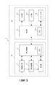
図1に示すように、粒子測定装置1は、光学検出ユニット100を備える。光学検出ユニット100は、フローセル110と、光源121、122と、光検出器131〜134と、光源121、122から出射されたレーザ光をフローセル110へと導く光学系140と、フローセル110を流れる粒子から生じた前方散乱光を対応する光検出器へと導く光学系150と、を備える。また、光学検出ユニット100は、フローセル110を流れる粒子から生じた側方散乱光および蛍光を、それぞれ、対応する光検出器へと導く第1の光学系160および第2の光学系170を備える。便宜上、図1には、互いに直交するXYZ座標軸が示されている。図1は、光学検出ユニット100をY軸負方向に見た図である。
As shown in FIG. 1, the
フローセル110内には、測定試料がシース液に包まれた状態で送り込まれる。図2(b)に示すように、フローセル110は、試料ノズル111と、シース液供給口112と、細孔部113と、廃液口114と、を備える。試料ノズル111は、測定試料を細孔部113に向かって上方へ噴射する。細孔部113内に、測定試料が流れる流路115が形成される。測定試料は、血球などの粒子を含んでいる。
A measurement sample is sent into the
図1に戻り、光源121は、発光部(図示せず)の半導体層の積層方向がZ軸方向に一致するよう配置される。したがって、光源121から出射されるレーザ光の広がり角は、Z軸方向において最大となり、Y軸方向において最小となる。光源121は、第1の波長の光をX軸負方向に出射する。第1の波長の光は、波長が約405nmであるレーザ光(以下、「青レーザ光L1」という)である。光源121の出射光軸は、光学系140の光軸Oに交差する。光軸OはZ軸に平行である。
Returning to FIG. 1, the
光源122は、発光部(図示せず)の半導体層の積層方向がX軸方向に一致するよう配置される。したがって、光源121から出射されるレーザ光の広がり角は、X軸方向において最大となり、Y軸方向において最小となる。光源122は、第2の波長の光をZ軸正方向に出射する。第2の波長の光は、波長が約640nmであるレーザ光(以下、「赤レーザ光L2」という)である。光源122の出射光軸は、光学系140の光軸Oに一致している。
The
光学系140は、コリメータレンズ141、142と、ダイクロイックミラー143と、シリンドリカルレンズ144と、コンデンサレンズ145と、を備える。
The
コリメータレンズ141は、光源121から出射された青レーザ光L1を平行光に変換する。コリメータレンズ142は、光源122から出射された赤レーザ光L2を平行光に変換する。ダイクロイックミラー143は、コリメータレンズ141を透過した青レーザ光L1を反射し、コリメータレンズ142を透過した赤レーザ光L2を透過する。ダイクロイックミラー143は、ダイクロイックミラー143によって反射された青レーザ光L1の進行方向が、図2(a)に示すように、Z軸方向からややY軸正方向に傾くように配置されている。
The
シリンドリカルレンズ144は、ダイクロイックミラー143を経由した青レーザ光L1と赤レーザ光L2をX軸方向にのみ収束させる。コンデンサレンズ145は、青レーザ光L1と赤レーザ光L2をY軸方向に収束させて、フローセル110の流路115の位置に合焦させる。また、コンデンサレンズ145は、青レーザ光L1と赤レーザ光L2をX軸方向に収束させて流路115のZ軸負側の位置に合焦させる。これにより、流路115には、図2(b)に示すように、X軸方向に細長いビーム形状で、青レーザ光L1と赤レーザ光L2が照射される。
The
図2(a)に示すように、ダイクロイックミラー143によって反射された青レーザ光L1は、Z軸方向からY軸方向にやや傾いた方向に進むため、流路115における青レーザ光L1の照射位置P1は、赤レーザ光L2の照射位置P2よりもY軸正方向にずれている。赤レーザ光L2の照射位置P2は、光軸O上にある。照射位置P1の粒子に対して青レーザ光L1が照射されると、青レーザ光L1が照射された粒子から、前方散乱光と、側方散乱光と、蛍光が生じる。照射位置P2の粒子に対して赤レーザ光L2が照射されると、赤レーザ光L2が照射された粒子から、前方散乱光と、側方散乱光と、蛍光が生じる。前方散乱光は、主として、フローセル110からZ軸正方向に向かう。側方散乱光は、主として、フローセル110からX軸正方向とX軸負方向に向かう。蛍光は、主として、フローセル110の周囲に広がる。
As shown in FIG. 2A, the blue laser light L1 reflected by the
以下、青レーザ光L1により生じる前方散乱光と、側方散乱光と、蛍光を、それぞれ、「青前方散乱光L11」、「青側方散乱光L12」、「青蛍光L13」と称する。赤レーザ光L2により生じる前方散乱光と、側方散乱光と、蛍光を、それぞれ、「赤前方散乱光L21」、「赤側方散乱光L22」、「赤蛍光L23」と称する。なお、青前方散乱光L11と青側方散乱光L12の波長は、青レーザ光L1と略同じであり、赤前方散乱光L21と赤側方散乱光L22の波長は、赤レーザ光L2と略同じである。青蛍光L13の波長と赤蛍光L23の波長は、青レーザ光L1の波長と赤レーザ光L2の波長と異なり、使用される試薬によって決まる。本実施形態では、青蛍光L13の波長は、430〜520nmであり、赤蛍光L23の波長は、660nmを超える波長帯である。 Hereinafter, the forward scattered light, the side scattered light, and the fluorescence generated by the blue laser light L1 are referred to as “blue forward scattered light L11”, “blue side scattered light L12”, and “blue fluorescence L13”, respectively. Forward scattered light, side scattered light, and fluorescence generated by the red laser light L2 are referred to as “red forward scattered light L21”, “red side scattered light L22”, and “red fluorescence L23”, respectively. The wavelengths of the blue forward scattered light L11 and the blue side scattered light L12 are substantially the same as those of the blue laser light L1, and the wavelengths of the red forward scattered light L21 and the red side scattered light L22 are substantially the same as those of the red laser light L2. The same. The wavelengths of the blue fluorescence L13 and the red fluorescence L23 are different from the wavelengths of the blue laser light L1 and the red laser light L2, and are determined by the reagents used. In this embodiment, the wavelength of the blue fluorescence L13 is 430 to 520 nm, and the wavelength of the red fluorescence L23 is a wavelength band exceeding 660 nm.
流路115内の粒子は、図2(b)に示すように、照射位置P2から照射位置P1へと流れる。このため、照射位置P2において粒子に赤レーザ光L2が照射されてから、照射位置P1において同じ粒子に青レーザ光L1が照射されるまでには、所定のタイムラグがある。そこで、粒子測定装置1は、このようなタイムラグを予め取得しておき、取得したタイムラグに基づいて、粒子ごとに、青レーザ光L1により生じる光の検出信号と、赤レーザ光L2により生じる光の検出信号を、互いに関連付けて取得する。
As shown in FIG. 2B, the particles in the
図1に戻り、光学系150は、集光レンズ151と、ビームストッパ152と、ピンホール153と、を備える。
Returning to FIG. 1, the
集光レンズ151は、アクロマティックレンズからなっており、青前方散乱光L11と赤前方散乱光L21に対して色収差を補正する機能を備える。集光レンズ151は、青前方散乱光L11と赤前方散乱光L21をピンホール153の位置に集光させる。また、集光レンズ151は、青レーザ光L1と赤レーザ光L2の一部であって、粒子に照射されずにフローセル110を透過した青レーザ光L1と赤レーザ光L2を、ビームストッパ152の位置に集光させる。
The
図2(a)に示すように、集光レンズ151は、その光軸が、Z軸と平行であり、且つ、光学系140の光軸OからY軸正方向にずれるように配置されている。これにより、青前方散乱光L11の中心を通る光線は、集光レンズ151を透過した後、Z軸正方向からややY軸負方向に傾く方向に進む。赤前方散乱光L21の中心を通る光線は、集光レンズ151を透過した後、Z軸正方向からややY軸正方向に傾く方向に進む。
As shown in FIG. 2A, the condensing
ビームストッパ152は、青前方散乱光L11と赤前方散乱光L21の大部分を通過させ、フローセル110を透過した青レーザ光L1と赤レーザ光L2を遮光する。ビームストッパ152は、光を透過しない薄板状の部材によって構成されている。図2(c)に示すように、ビームストッパ152は、半円状の開口152a、152bと、開口152a、152b間に形成された遮光部152cと、を備える。ビームストッパ152は、青レーザ光L1と赤レーザ光L2のX軸方向の焦点位置に位置付けられるように配置される。これにより、青レーザ光L1と赤レーザ光L2は、遮光部152c上でY軸方向に長いビーム形状となり、遮光部152cによって遮光される。青前方散乱光L11と赤前方散乱光L21の大部分は、開口152a、152bを介してビームストッパ152を通過する。
The
図2(d)に示すように、ピンホール153は、Y軸方向に並ぶ2つの孔153a、153bを備える。青前方散乱光L11は、孔153aの位置に集光され、赤前方散乱光L21は、孔153bの位置に集光される。青前方散乱光L11と赤前方散乱光L21は、それぞれ、孔153a、153bを通り抜けて、光検出器131により受光される。
As shown in FIG. 2D, the
図2(e)に示すように、光検出器131は、フォトダイオードであり、Y軸方向に並ぶ2つの受光面131a、131bを備える。受光面131a、131bは、同一平面上に配置されている。青前方散乱光L11と赤前方散乱光L21は、それぞれ、受光面131a、131bに照射される。光検出器131は、青前方散乱光L11に基づく信号(以下、「信号BFSC」という)と、赤前方散乱光L21に基づく信号(以下、「信号RFSC」という)を出力する。
As shown in FIG. 2E, the
図1に戻り、第1の光学系160は、第1レンズ161と、第1絞り部材162と、ダイクロイックミラー163と、集光レンズ164と、分光フィルタ165と、集光レンズ166と、を備える。第1レンズ161は、その光軸が、フローセル110の流路115を通るX軸に平行な直線と一致するように配置されている。
Returning to FIG. 1, the first
第1レンズ161は、コリメータレンズであり、青側方散乱光L12と、赤側方散乱光L22と、青蛍光L13と、赤蛍光L23のうち、青蛍光L13と赤蛍光L23を、略平行光に変換する。第1絞り部材162は、円形の開口162aを備える。開口162aの中心は、第1レンズ161の光軸を通るX軸に平行な直線上にある。第1絞り部材162は、第1レンズ161を透過して光検出器132、133へと導かれる光束の径を規定する。第1レンズ161と第1絞り部材162により、フローセル110に対する第1の光学系160の開口数が設定される。一般に、開口数は、NA=n・sinθで表される。
The
ダイクロイックミラー163は、赤側方散乱光L22をZ軸正方向に反射し、青側方散乱光L12と、青蛍光L13と、赤蛍光L23を透過する。ダイクロイックミラー163の透過波長帯域は、青側方散乱光L12と、青蛍光L13と、赤蛍光L23を透過可能なように設定される。
The
集光レンズ164は、ダイクロイックミラー163により反射された赤側方散乱光L22を集光する。光検出器132は、フォトダイオードであり、受光面132aを備える。赤側方散乱光L22は、受光面132aに集光される。光検出器132は、赤側方散乱光L22に基づく信号(以下、「信号RSSC」という)を出力する。
The condensing
分光フィルタ165は、ダイクロイックミラー163を透過した青側方散乱光L12を吸収し、ダイクロイックミラー163を透過した青蛍光L13と赤蛍光L23を透過する。分光フィルタ165の吸収波長帯域は、青側方散乱光L12を吸収可能で、且つ、青蛍光L13と赤蛍光L23を透過可能に設定される。
The
集光レンズ166は、分光フィルタ165を透過した青蛍光L13と赤蛍光L23を集光する。光検出器133は、アバランシェフォトダイオードであり、青蛍光L13と赤蛍光L23を受光する。光検出器133は、青蛍光L13の集光領域と赤蛍光L23の集光領域の両方をカバーする広さの一つの受光面を有する。これに替えて、光検出器133は、青蛍光L13のみ受光する受光面と、赤蛍光L23のみを受光する受光面とを備えても良い。光検出器133は、青蛍光L13に基づく信号(以下、「信号BFL」という)と、赤蛍光L23に基づく信号(以下、「信号RFL」という)を出力する。なお、粒子測定装置1は、光源121、122の何れか一方を駆動させることにより、青蛍光L13に基づく信号と、赤蛍光L23に基づく信号を取得する。
The
第2の光学系170は、第2レンズ171と、第2絞り部材172と、反射板173と、を備える。第2レンズ171は、その光軸が、フローセル110の流路115を通るX軸に平行な直線と一致するように配置されている。
The second
第2レンズ171は、コリメータレンズであり、青側方散乱光L12と、赤側方散乱光L22と、青蛍光L13と、赤蛍光L23のうち、青蛍光L13を、平行光に変換する。第2絞り部材172は、円形の開口172aを備える。開口172aの中心は、第2レンズ171の光軸を通るX軸に平行な直線上にある。第2絞り部材172は、第2レンズ171を透過する光束の径を規定する。第2レンズ171と第2絞り部材172により、フローセル110に対する第2の光学系170の開口数が設定される。
The
ここで、フローセル110に対する第2の光学系170の開口数は、フローセル110に対する第1の光学系160の開口数より小さくなるよう、第1の光学系160と第2の光学系170が設定されている。具体的には、第1レンズ161と、第1絞り部材162と、第2レンズ171と、第2絞り部材172について、構成と配置が所望の状態となるように設定される。かかる設定については、追って図5(a)を参照して説明する。
Here, the first
反射板173の入射面には、赤側方散乱光L22と赤蛍光L23を吸収し、青側方散乱光L12を透過し、青蛍光L13を反射する膜構造が形成されている。光検出器134は、フォトダイオードであり、受光面134aを備える。青側方散乱光L12は、受光面134aに照射される。光検出器134は、青側方散乱光L12に基づく信号(以下、「信号BSSC」という)を出力する。
A film structure that absorbs the red side scattered light L22 and the red fluorescent light L23, transmits the blue side scattered light L12, and reflects the blue fluorescent light L13 is formed on the incident surface of the reflecting
反射板173により反射された青蛍光L13は、X軸正方向に進んで、再び第2絞り部材172と第2レンズ171を通り、フローセル110に入射する。そして、第2レンズ171側からフローセル110に入射した青蛍光L13は、フローセル110を透過し、流路115の粒子からX軸正方向に生じた青蛍光L13と同様に、第1の光学系160により光検出器133に導かれる。
The blue fluorescence L13 reflected by the reflecting
図3を参照して、粒子測定装置1は、測定ユニット10と情報処理ユニット20を備える。
With reference to FIG. 3, the
測定ユニット10は、測定制御部11と、検体吸引部12と、試料調製部13と、検出部14と、を備える。測定制御部11は、メモリ11aを備え、検出部14は、図1に示す光学検出ユニット100を含んでいる。測定制御部11は、測定ユニット10の各部を駆動し、各部から出力された信号を受信する。また、測定制御部11は、情報処理ユニット20との間で信号の送受信を行う。情報処理ユニット20は、制御部21と、出力部22と、入力部23と、ハードディスク24と、を備える。制御部21は、メモリ21aを備える。制御部21は、情報処理ユニット20の各部を駆動し、各部から出力された信号を受信する。また、制御部21は、測定ユニット10との間で信号の送受信を行う。出力部22は、ディスプレイである。入力部23は、マウスやキーボードである。
The
粒子測定装置1の動作は、以下のとおりである。
The operation of the
検体吸引部12は、患者から採取された末梢血である血液検体を検体容器から吸引し、吸引した血液検体を試料調製部13に送る。試料調製部13は、検体に試薬等を混和することにより、測定に用いられる測定試料を調製する。検出部14は、光検出器131〜134(図1参照)から出力された信号BFSC、RFSC、BSSC、RSSC、BFL、RFLを、測定制御部11に出力する。測定制御部11は、信号BFSC、RFSC、BSSC、RSSC、BFL、RFLの波形から、それぞれ、ピーク値、幅、面積等の複数の特徴パラメータを算出する。メモリ11aは、粒子ごとに複数の特徴パラメータを対応付けて記憶する。測定制御部11は、測定が終了すると、メモリ11aに記憶した粒子ごとの特徴パラメータを、情報処理ユニット20に送信する。
The
制御部21は、測定ユニット10から粒子ごとの特徴パラメータを受信すると、ハードディスク24に記憶されているコンピュータプログラムに基づいて解析処理を行い、ハードディスク24は、解析結果を記憶する。制御部21は、入力部23を介して解析結果の表示指示を受け付けると、解析結果を含む映像信号を出力部22に出力する。出力部22は、映像信号に基づいて画像を表示する。
When the
次に、解析処理において行われる粒子の分類について説明する。制御部21は、解析処理において、信号BFSC、RFSC、BSSC、RSSC、BFL、RFLから得られた複数の特徴パラメータを組み合わせて、粒子ごとの分類を行う。
Next, the particle classification performed in the analysis process will be described. In the analysis processing, the
図4(a)を参照して、制御部21は、測定試料に含まれる粒子を、赤血球と、白血球と、血小板に分類する場合、青前方散乱光L11と赤前方散乱光L21に基づくスキャッタグラムSG1を用いる。スキャッタグラムSG1の縦軸と横軸は、それぞれ、信号RFSCのピーク値と、信号BFSCのピーク値である。制御部21は、測定試料中の各粒子をスキャッタグラムSG1上にプロットし、スキャッタグラムSG1に領域A1〜A3を設定する。こうして、制御部21は、領域A1〜A3に含まれる粒子を、それぞれ赤血球と、血小板と、白血球に分類する。
Referring to FIG. 4A, when the
なお、図4(a)に示すように、スキャッタグラムSG1において、赤血球が分布する領域A1と白血球が分布する領域A2は、互いに重ならない。この理由は、赤血球と白血球とで、青レーザ光L1の吸収度合いが異なるためである。 As shown in FIG. 4A, in the scattergram SG1, a region A1 where red blood cells are distributed and a region A2 where white blood cells are distributed do not overlap each other. This is because red blood cells and white blood cells have different absorption levels of the blue laser light L1.
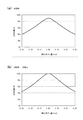
図4(b)には、酸素化ヘモグロビン(HbO2)と脱酸素化ヘモグロビン(Hb)の吸収係数がそれぞれ示されている。一般に、静脈血の赤血球中には、酸素化ヘモグロビンと脱酸素化ヘモグロビンが、3対1の割合で存在しているため、測定試料に含まれる赤血球では、酸素化ヘモグロビンの性質が支配的である。図4(b)に示すように、波長が400〜435nmの範囲では、酸素化ヘモグロビンの吸収係数は、他の波長帯に比べて数段大きくなっている。一方、波長が610〜750nmの範囲では、酸素化ヘモグロビンの吸収係数は、他の波長帯に比べて数段小さくなっている。したがって、血液検体中の赤血球は、赤レーザ光L2よりも青レーザ光L1をより吸収する。他方、血小板や白血球などの他の血球は、ヘモグロビンを含んでいないため、他の血球は、青レーザ光L1と赤レーザ光L2を同程度吸収する。 FIG. 4B shows the absorption coefficients of oxygenated hemoglobin (HbO 2 ) and deoxygenated hemoglobin (Hb), respectively. In general, oxygenated hemoglobin and deoxygenated hemoglobin are present at a ratio of 3 to 1 in erythrocytes of venous blood. Therefore, the properties of oxygenated hemoglobin are dominant in the erythrocytes contained in the measurement sample. . As shown in FIG. 4B, in the wavelength range of 400 to 435 nm, the absorption coefficient of oxygenated hemoglobin is several steps larger than other wavelength bands. On the other hand, in the wavelength range of 610 to 750 nm, the absorption coefficient of oxygenated hemoglobin is several steps smaller than other wavelength bands. Therefore, red blood cells in the blood sample absorb blue laser light L1 more than red laser light L2. On the other hand, since other blood cells such as platelets and white blood cells do not contain hemoglobin, the other blood cells absorb blue laser light L1 and red laser light L2 to the same extent.
よって、赤血球では、青前方散乱光L11のピーク値は、赤前方散乱光L21のピーク値よりも小さくなり易く、他の血球では、青前方散乱光L11のピーク値と赤前方散乱光L21のピーク値は、同程度になり易い。このことから、赤血球を示す粒子は、領域A1近傍に分布し、白血球を示す粒子は、領域A3近傍に分布する。また、赤血球は分布曲線C1に沿うように分布し、血小板と白血球は分布曲線C2上に位置している。以上のことから、図4(a)に示すスキャッタグラムSG1によれば、赤血球と、白血球と、血小板を、良好に分類することができる。 Therefore, in red blood cells, the peak value of the blue forward scattered light L11 tends to be smaller than the peak value of the red forward scattered light L21, and in other blood cells, the peak value of the blue forward scattered light L11 and the peak of the red forward scattered light L21. The value tends to be comparable. Therefore, particles indicating red blood cells are distributed in the vicinity of the region A1, and particles indicating white blood cells are distributed in the vicinity of the region A3. Red blood cells are distributed along the distribution curve C1, and platelets and white blood cells are located on the distribution curve C2. From the above, according to the scattergram SG1 shown in FIG. 4A, red blood cells, white blood cells, and platelets can be classified well.
図4(c)を参照して、制御部21は、測定試料に含まれる粒子を、白血球を3つに分類する場合、青前方散乱光L11と赤前方散乱光L21に基づくスキャッタグラムSG2を用いる。スキャッタグラムSG2の2軸は、図4(a)に示すスキャッタグラムSG1と同じである。制御部21は、測定試料中の各粒子をスキャッタグラムSG2上にプロットし、スキャッタグラムSG2に領域A10、A3、A31〜A33を設定する。領域A10に含まれる粒子は除外される。こうして、制御部21は、領域A31〜A33に含まれる粒子を、それぞれリンパ球と、単球と、顆粒球に分類する。
With reference to FIG.4 (c), the
図4(d)を参照して、制御部21は、測定試料に含まれる粒子を、表面抗原CD4を有するリンパ球と、表面抗原CD4を有さないリンパ球に分類する場合、図4(c)に示すスキャッタグラムSG2に加えて、赤前方散乱光L21と赤蛍光L23に基づくスキャッタグラムSG3を用いる。スキャッタグラムSG3の縦軸と横軸は、それぞれ、信号RFSCのピーク値と、信号RFLのピーク値である。制御部21は、スキャッタグラムSG2の領域A33に含まれる各粒子を、スキャッタグラムSG3上にプロットし、スキャッタグラムSG3に領域A41、A42を設定する。こうして、制御部21は、領域A41、A42に含まれる粒子を、それぞれ表面抗原CD4を有するリンパ球と、表面抗原CD4を有さないリンパ球に分類する。
Referring to FIG. 4D, when the
図4(e)、(f)を参照して、制御部21は、測定試料に含まれる白血球を3つに分類する場合、青前方散乱光L11と赤前方散乱光L21に基づくスキャッタグラムSG4と、赤前方散乱光L21と赤側方散乱光L22に基づくスキャッタグラムSG5を用いることもできる。スキャッタグラムSG4の2軸は、図4(c)に示すスキャッタグラムSG2と同じである。スキャッタグラムSG5の縦軸と横軸は、それぞれ、信号RFSCのピーク値と、信号RSSCのピーク値をログ表示した値である。制御部21は、測定試料中の各粒子をスキャッタグラムSG4上にプロットし、スキャッタグラムSG4に領域A10、A5を設定する。制御部21は、領域A10に含まれる粒子を除外した後、領域A5に含まれる各粒子を、スキャッタグラムSG5上にプロットし、スキャッタグラムSG5に領域A51〜A53を設定する。こうして、制御部21は、領域A51〜A53に含まれる粒子を、それぞれリンパ球と、単球と、顆粒球に分類する。
Referring to FIGS. 4E and 4F, when classifying the white blood cells contained in the measurement sample into three, the
その他、制御部21は、測定試料に含まれる粒子を、マラリア感染赤血球と、それ以外の粒子とに分類する場合、青前方散乱光L11と青蛍光L13に基づくスキャッタグラムを用いることもできる。測定試料の作製において所定の蛍光色素が用いられると、核のない赤血球は染色されず、マラリア原虫のDNAが染色される。これにより、制御部21は、信号BFSCのピーク値と信号BFLのピーク値とを2軸とするスキャッタグラムに基づいて、マラリア感染赤血球と、それ以外の血球とを分類することができる。
In addition, the
測定制御部11は、測定粒子に含まれる粒子を識別する際に、青側方散乱光L12に基づく信号を用いることもできる。測定制御部11は、青レーザ光L1に基づく信号を用いることにより、青レーザ光L1よりも長波長である赤レーザ光L2に基づく信号を用いる場合に比べて、より微小な粒子を識別することができる。また、青前方散乱光L11には、フローセル110を透過した青レーザ光L1が漏れ込み易い。このため、測定制御部11は、青側方散乱光L12に基づく信号を用いることにより、青前方散乱光L11に基づく信号を用いる場合に比べて、S/N比を高めることができる。よって、測定制御部11は、青側方散乱光L12に基づく信号を用いることにより、精度よく粒子を識別することができる。
The
次に、第1の光学系160の開口数と第2の光学系170の開口数について説明する。
Next, the numerical aperture of the first
図5(a)に示すように、第1レンズ161と第2レンズ171は、焦点距離がf1となるよう構成される。第1絞り部材162の開口162aは、直径がφ1となるよう設定され、第2絞り部材172の開口172aは、直径がφ1よりも小さいφ2となるよう設定される。すなわち、第1絞り部材162の開口径はφ1であり、第2絞り部材172の開口径はφ2である。このとき、流路115のX軸正側では、角度θ1の広がり範囲において、流路115からの光が第1絞り部材162を通過して第1の光学系160に取り込まれる。また、流路115のX軸負側では、角度θ1よりも小さい角度θ2の広がり範囲において、流路115からの光が第2絞り部材172を通過して第2の光学系170に取り込まれる。このように、第1レンズ161と、第1絞り部材162と、第2レンズ171と、第2絞り部材172が設定されると、フローセル110に対する第2の光学系170の開口数は、フローセル110に対する第1の光学系160の開口数より小さくなる。
As shown in FIG. 5A, the
なお、フローセル110に対する第1の光学系160の開口数とは、フローセル110から生じた光のうち、第1の光学系160に取り込まれて対応する光検出器へと導かれる光により規定される。すなわち、この光がフローセル110からX軸正方向に向かうときの広がり角θ1により、フローセル110に対する第1の光学系160の開口数が定義される。また、フローセル110に対する第2の光学系170の開口数とは、フローセル110から生じた光のうち、第2の光学系170に取り込まれて反射され、第1の光学系160へと導かれる光により規定される。すなわち、この光がフローセル110からX軸負方向に向かうときの広がり角θ2により、フローセル110に対する第2の光学系170の開口数が定義される。
Note that the numerical aperture of the first
たとえば、図5(b)に示すように、第2レンズ171からX軸負方向に離れて第2絞り部材172が設置される場合、第2の光学系170により反射されて第1の光学系160へと導かれる光の範囲は、角度θ2の範囲である。このように透過光が平行光になっている場合は、第2絞り部材172のX軸方向の位置が変わっても、フローセル110に対する第2の光学系170の開口数は、図5(a)の場合と同じく、第1の光学系160へと導かれる光の範囲に対応する角度θ2によって定義される。
For example, as shown in FIG. 5B, when the
図5(a)には、反射板173により反射される光(以下、「反射光」という)の光束が、破線により示されており、第2の光学系170を介さずに第1レンズ161に入射する光の光束が、実線により示されている。反射光の光束の直径は、第2絞り部材172により、φ2に規制される。このため、反射光は、流路115から、角度θ1よりも小さい角度θ2で第1絞り部材162に入射し、反射光は、第1絞り部材162を通る際に、開口162aの内側を通るようになる。これにより、第1の光学系160と第2の光学系170とに含まれる光学部品の配置に多少のばらつきが生じていても、反射光は、第1絞り部材162の開口162aから外れにくくなる。よって、光学部品の配置のばらつきによって、光検出器133に入射する反射光の光量が、大きく変化することがない。
In FIG. 5A, a light flux of light reflected by the reflecting plate 173 (hereinafter referred to as “reflected light”) is indicated by a broken line, and the
次に、本発明者が行ったシミュレーション結果について説明する。本発明者は、光学部品の配置にばらつきが生じている場合の例として、第2レンズ171と第2絞り部材172(以下、「反射側部材」という)が位置ずれを生じている場合を想定した。本発明者は、この場合に、光検出器133が検出する受光光量がどのように変化するかを検討した。
Next, simulation results performed by the present inventor will be described. The present inventor assumes a case where the
まず、図6(a)〜図13(b)を参照して、比較例のシミュレーション結果について説明する。比較例では、第2絞り部材172の開口172aの直径φ2が、第1絞り部材162の開口162aの直径φ1と同じである。すなわち、比較例では、フローセル110に対する第2の光学系170の開口数が、フローセル110に対する第1の光学系160の開口数と同じである。
First, the simulation results of the comparative example will be described with reference to FIGS. 6 (a) to 13 (b). In the comparative example, the diameter φ2 of the
図6(b)に示すように、反射側部材がずれていない場合、X軸正方向に進む反射光は、第2絞り部材172と第1絞り部材162によって遮光されることがない。一方、図6(a)に示すように、反射側部材がX軸方向に−0.3mmずれている場合、反射光の周辺部は、第2絞り部材172により遮光される。また、図6(c)に示すように、反射側部材がX軸方向に+0.3mmずれている場合、反射光の周辺部は、第1絞り部材162により遮光される。
As shown in FIG. 6B, when the reflection side member is not displaced, the reflected light traveling in the positive direction of the X axis is not shielded by the
図7(a)に示すように、反射側部材がX軸方向にずれると、光検出器133が検出する受光光量は、ズレ量に応じて減少する。図7(b)は、図7(a)のグラフが、最大の受光光量で正規化されたものである。図7(b)に示すように、X軸方向のズレ量が+0.3mmであるときの受光光量は、最大の受光光量に比べて約43%も減少してしまう。
As shown in FIG. 7A, when the reflection side member is displaced in the X-axis direction, the amount of received light detected by the
図8(b)に示すように、反射側部材がずれていない場合、X軸正方向に進む反射光は、第2絞り部材172と第1絞り部材162によって遮光されることがない。一方、図8(a)、(c)に示すように、反射側部材がY軸方向に0.3mmずれている場合、反射光の周辺部は、第2絞り部材172と第1絞り部材162により遮光される。
As shown in FIG. 8B, when the reflection side member is not displaced, the reflected light traveling in the positive X-axis direction is not shielded by the
図9(a)に示すように、反射側部材がY軸方向にずれると、光検出器133が検出する受光光量は、ズレ量に応じて減少する。図9(b)は、図9(a)のグラフが、最大の受光光量で正規化されたものである。図9(b)に示すように、Y軸方向のズレ量が0.15mmと0.3mmであるときの受光光量は、最大の受光光量に比べて、それぞれ、約30%と約56%も減少してしまう。
As shown in FIG. 9A, when the reflection-side member is displaced in the Y-axis direction, the amount of received light detected by the
なお、反射側部材がY軸方向にずれた場合の反射光の挙動と、反射側部材がZ軸方向にずれた場合の反射光の挙動は、原理的に同じである。したがって、反射側部材がZ軸方向にずれている場合のシミュレーション結果も、図8(a)〜図9(b)と同様である。 The behavior of the reflected light when the reflection side member is displaced in the Y-axis direction and the behavior of the reflected light when the reflection side member is displaced in the Z-axis direction are the same in principle. Therefore, the simulation results when the reflection-side member is displaced in the Z-axis direction are the same as those in FIGS. 8A to 9B.
次に、実施形態1のシミュレーション結果について説明する。
Next, the simulation result of
図10(b)に示すように、反射側部材がずれていない場合、X軸正方向に進む反射光は、第2絞り部材172と第1絞り部材162によって遮光されることがない。一方、図10(a)、(b)に示すように、反射側部材がX軸方向に0.3mmずれている場合、反射光の周辺部は、第2絞り部材172により僅かに遮光される。しかしながら、反射光は、第1絞り部材162により略遮光されない。この理由は、図5(a)を参照して説明したように、第1絞り部材162を通る際の反射光の範囲が、開口162aよりも狭く、反射光と開口162aとの間に隙間があるためである。
As shown in FIG. 10B, when the reflection side member is not displaced, the reflected light traveling in the positive X-axis direction is not shielded by the
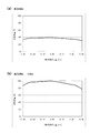
図11(a)に示すように、反射側部材がX軸方向にずれると、光検出器133が検出する受光光量は、ズレ量に応じて僅かに減少する。図11(b)は、図11(a)のグラフが、最大の受光光量で正規化されたものである。図11(b)に示すように、X軸方向のズレ量が+0.3mmであるときの受光光量は、最大の受光光量に比べて約20%の減少に抑えられている。これに対し、比較例では、上記のように、X軸方向のズレ量が+0.3mmであるときの受光光量は、最大の受光光量に比べて約43%減少する。よって、実施形態1では、反射側部材がX軸方向にずれた場合でも、比較例に比べて、受光光量の減少割合が低く抑えられることが分かる。
As shown in FIG. 11A, when the reflection-side member is displaced in the X-axis direction, the amount of received light detected by the
図12(b)に示すように、反射側部材がずれていない場合、X軸正方向に進む反射光は、第2絞り部材172と第1絞り部材162によって遮光されることがない。一方、図12(a)、(c)に示すように、反射側部材がY軸方向に0.3mmずれている場合、反射光の周辺部は、第2絞り部材172と第1絞り部材162により遮光される。
As shown in FIG. 12B, when the reflection side member is not displaced, the reflected light traveling in the positive direction of the X axis is not shielded by the
図13(a)に示すように、反射側部材がY軸方向にずれると、光検出器133が検出する受光光量は、ズレ量に応じて減少する。図13(b)は、図13(a)のグラフが、最大の受光光量で正規化されたものである。図13(b)に示すように、Y軸方向のズレ量が0.15mmと0.3mmであるときの受光光量は、最大の受光光量に比べて、それぞれ、約15%と約46%の減少に抑えられている。これに対し、比較例では、上記のように、Y軸方向のズレ量が0.15mmと0.3mmであるときの受光光量は、最大の受光光量に比べて、それぞれ、約30%と約56%減少する。よって、実施形態1では、反射側部材がY軸方向にずれた場合でも、比較例に比べて、受光光量の減少割合が低く抑えられることが分かる。また、実施形態1では、反射側部材がY軸方向にずれた場合、比較例に比べて、受光光量の減少が緩やかである。特に、Y軸方向のずれ量が小さい範囲では、受光光量の減少割合が低く抑えられることが分かる。
As shown in FIG. 13A, when the reflection side member is displaced in the Y-axis direction, the amount of received light detected by the
なお、反射側部材がZ軸方向にずれている場合のシミュレーション結果も、図12(a)〜図13(b)と同様である。よって、反射側部材がZ軸方向にずれている場合も、比較例に比べて、受光光量の減少が低く抑えられることが分かる。 Note that the simulation results when the reflection-side member is displaced in the Z-axis direction are also the same as in FIGS. 12 (a) to 13 (b). Therefore, it can be seen that even when the reflection-side member is displaced in the Z-axis direction, the decrease in the amount of received light can be suppressed lower than in the comparative example.
以上、実施形態1によれば、フローセル110に対する第2の光学系170の開口数が、フローセル110に対する第1の光学系160の開口数より小さく設定されている。このため、反射光の広がり角が、第1の光学系160の開口数により規定される角度範囲よりも小さくなる。すなわち、反射光は、角度θ1よりも小さい角度θ2で第1絞り部材162に入射し、反射光と開口162aとの間に隙間が生じる。これにより、第1レンズ161と、第1絞り部材162と、第2レンズ171と、第2絞り部材172等の光学部品の配置に多少のばらつきが生じても、反射光は、第1の光学系160の光の取り込み範囲から外れにくくなる。よって、光学部品にばらつきが生じても、光検出器133により検出される反射光の光量変動が抑えられる。具体的には、光検出器133により検出される青蛍光L13の光量変動が抑えられる。
As described above, according to the first embodiment, the numerical aperture of the second
実施形態1によれば、反射板173は、流路115の粒子からX軸負方向に生じた青蛍光L13を反射する。これにより、光検出器133は、流路115の粒子からX軸正方向に生じた青蛍光L13と、流路115の粒子からX軸負方向に生じた青蛍光L13とを受光することができる。よって、光検出器133による青蛍光L13の検出光量を増強することができる。
According to the first embodiment, the reflecting
実施形態1によれば、フローセル110に対する第1の光学系160の開口数は、第1レンズ161に第1絞り部材162を組み合わせることにより、第1レンズ161の開口数として設定され、フローセル110に対する第2の光学系170の開口数は、第2レンズ171に第2絞り部材172を組み合わせることにより、第2レンズ171の開口数として設定される。このため、第1絞り部材162の開口径φ1を調整することで、第1の光学系160の開口数を容易に設定することができ、また、第2絞り部材172の開口径φ2を調整することで、第2の光学系170の開口数を容易に設定することができる。さらに、第1絞り部材162と第2絞り部材172の開口径により、第1の光学系160と第2の光学系170の開口数を設定できるため、第1レンズ161と第2レンズ171として、焦点距離f1が同一のレンズを用いることができる。これにより、第1レンズ161と第2レンズ171にかかるコストを抑えることができる。
According to the first embodiment, the numerical aperture of the first
実施形態1によれば、反射板173は、青側方散乱光L12を透過させて光検出器134へと導く。このため、第1の光学系160に青側方散乱光L12を受光するための構成が不要となり、第1の光学系160の光学設計が容易になる。また、反射板173のX軸負側に光検出器134を配置するのみで青側方散乱光L12を受光できるため、光学系全体の構成を簡素にすることができる。
According to the first embodiment, the reflecting
<実施形態2>
<
図14に示すように、実施形態2は、実施形態1に比べて、第2レンズ171の焦点距離がf1よりも大きいf2に変更されたことが相違している。第2絞り部材172の開口172aの直径は、第1絞り部材162の開口162aの直径と同じφ1である。実施形態2のその他の構成は、実施形態1と同様である。
As shown in FIG. 14, the second embodiment is different from the first embodiment in that the focal length of the
図14に示すように、実施形態2では、焦点距離f2は、f2/φ1=f1/φ2となるよう設定される。これにより、フローセル110に対する第2の光学系170の開口数は、実施形態1と同じになっている。よって、実施形態2でも、フローセル110に対する第2の光学系170の開口数は、フローセル110に対する第1の光学系160の開口数より小さくなる。これにより、光学部品の配置に多少のばらつきが生じていても、反射光は、第1の光学系160の光の取り込み範囲から外れにくくなるため、実施形態1と同様の効果が奏され得る。なお、必ずしもフローセル110に対する第2の光学系170の開口数が上記実施形態1と同じでなくとも良く、フローセル110に対する第2の光学系170の開口数は、フローセル110に対する第1の光学系160の開口数よりも小さければ良い。
As shown in FIG. 14, in the second embodiment, the focal length f2 is set to satisfy f2 / φ1 = f1 / φ2. Thereby, the numerical aperture of the second
実施形態2では、第1レンズ161と第2レンズ171として、異なるレンズを用いる必要があるものの、第1絞り部材162と第2絞り部材172として、同じ部材を用いることができる。
In the second embodiment, different lenses need to be used as the
次に、図15(a)〜図18(b)を参照して、本発明者が行った実施形態2のシミュレーション結果について説明する。以下に示すシミュレーション結果は、図10(a)〜図13(b)に示したシミュレーション結果と、同様の条件で行ったものである。なお、比較例については、図6(a)〜図9(b)に示す通りであるため、ここでは説明を省略する。 Next, with reference to FIG. 15A to FIG. 18B, a simulation result of the second embodiment performed by the present inventor will be described. The simulation results shown below were performed under the same conditions as the simulation results shown in FIGS. 10 (a) to 13 (b). In addition, about a comparative example, since it is as showing to Fig.6 (a)-FIG.9 (b), description is abbreviate | omitted here.
図15(b)に示すように、反射側部材がずれていない場合、X軸正方向に進む反射光は、第2絞り部材172と第1絞り部材162によって遮光されることがない。一方、図15(a)、(b)に示すように、反射側部材がX軸方向に0.3mmずれている場合、実施形態1と同様、反射光の周辺部は、第2絞り部材172により僅かに遮光されるが、反射光は、第1絞り部材162により略遮光されない。
As shown in FIG. 15B, when the reflection-side member is not displaced, the reflected light traveling in the positive direction of the X axis is not shielded by the
図16(a)に示すように、反射側部材がX軸方向にずれると、光検出器133が検出する受光光量は、ズレ量に応じて僅かに減少する。図16(b)は、図16(a)のグラフが、最大の受光光量で正規化されたものである。図16(b)に示すように、X軸方向のズレ量が+0.3mmであるときの受光光量は、最大の受光光量に比べて、約12%の減少に抑えられている。よって、実施形態2では、反射側部材がX軸方向にずれた場合でも、比較例に比べて、受光光量の減少割合が低く抑えられることが分かる。
As shown in FIG. 16A, when the reflection-side member is displaced in the X-axis direction, the amount of received light detected by the
図17(b)に示すように、反射側部材がずれていない場合、X軸正方向に進む反射光は、第2絞り部材172と第1絞り部材162によって遮光されることがない。一方、図17(a)、(c)に示すように、反射側部材がY軸方向に0.3mmずれている場合、実施形態1と同様、反射光の周辺部は、第2絞り部材172と第1絞り部材162により遮光される。
As shown in FIG. 17B, when the reflection side member is not displaced, the reflected light traveling in the positive X-axis direction is not shielded by the
図18(a)に示すように、反射側部材がY軸方向にずれると、光検出器133が検出する受光光量は、ズレ量に応じて減少する。図18(b)は、図18(a)のグラフが、最大の受光光量で正規化されたものである。図18(b)に示すように、Y軸方向のズレ量が0.3mmであるときの受光光量は、最大の受光光量に比べて約23%の減少に抑えられている。よって、実施形態2では、反射側部材がY軸方向にずれた場合でも、比較例に比べて、受光光量の減少割合が低く抑えられることが分かる。
As shown in FIG. 18A, when the reflection-side member is displaced in the Y-axis direction, the amount of received light detected by the
なお、反射側部材がZ軸方向にずれている場合のシミュレーション結果も、図17(a)〜図18(b)と同様である。よって、反射側部材がZ軸方向にずれている場合も、比較例に比べて、受光光量の減少が低く抑えられることが分かる。 Note that the simulation results when the reflection-side member is displaced in the Z-axis direction are also the same as those shown in FIGS. 17 (a) to 18 (b). Therefore, it can be seen that even when the reflection-side member is displaced in the Z-axis direction, the decrease in the amount of received light can be suppressed lower than in the comparative example.
<実施形態3> <Embodiment 3>
図19(b)に示すように、実施形態3は、実施形態1(図19(a)に再掲)に比べて、第2レンズ171の焦点距離がf1よりも小さいf3に変更され、第2絞り部材172の開口172aの直径がφ2よりも小さいφ3に変更されたものである。なお、実施形態3のその他の構成については、実施形態1と同様である。
As shown in FIG. 19B, in the third embodiment, the focal length of the
図19(b)に示すように、焦点距離f3と直径φ3は、f3/φ3=f1/φ2となるよう設定される。これにより、フローセル110に対する第2の光学系170の開口数は、実施形態1、3と同じになっている。よって、実施形態3でも、フローセル110に対する第2の光学系170の開口数は、フローセル110に対する第1の光学系160の開口数より小さくなる。これにより、光学部品の配置に多少のばらつきが生じていても、反射光は、第1の光学系160の光の取り込み範囲から外れにくくなるため、実施形態1と同様の効果が奏され得る。なお、必ずしもフローセル110に対する第2の光学系170の開口数が上記実施形態1、3と同じでなくとも良く、フローセル110に対する第2の光学系170の開口数は、フローセル110に対する第1の光学系160の開口数よりも小さければ良い。
As shown in FIG. 19B, the focal length f3 and the diameter φ3 are set to satisfy f3 / φ3 = f1 / φ2. Thereby, the numerical aperture of the second
実施形態3では、図19(b)に示すように、反射板173に照射される青側方散乱光L12の直径はφ3であり、実施形態1の場合のφ2よりも小さくなる。これにより、実施形態3では、青側方散乱光L12を受光する光検出器134の受光面134a(図1参照)を小さくしても、実施形態1と同様の光量の青側方散乱光L12を受光することができる。このため、光検出器134の小型化を図ることができる。
In the third embodiment, as shown in FIG. 19B, the diameter of the blue side scattered light L12 irradiated on the reflecting
なお、焦点距離f3は焦点距離f1よりも小さいため、実施形態3の第2絞り部材172の開口径が、実施形態1の第2絞り部材172の開口径と同様、φ2であると、フローセル110に対する第2の光学系170の開口数は、フローセル110に対する第1の光学系160の開口数より大きくなる場合がある。しかしながら、実施形態3では、第2絞り部材172の開口径φ3が、実施形態1の開口径φ2よりも小さく設定されているため、フローセル110に対する第2の光学系170の開口数は、フローセル110に対する第1の光学系160の開口数よりも小さくなっている。
Since the focal length f3 is smaller than the focal length f1, the flow diameter of the
<実施形態4> <Embodiment 4>
図20に示すように、実施形態4は、実施形態1に比べて、青レーザ光L1を照射および受光するための構成が省略されている。 As shown in FIG. 20, in the fourth embodiment, the configuration for irradiating and receiving the blue laser light L1 is omitted as compared with the first embodiment.
具体的には、光源121と、光検出器131の受光面131aと、光検出器134と、コリメータレンズ141と、ダイクロイックミラー143と、ピンホール153の孔153aと、が省略され、反射板173に替えて、光を全反射するミラー174が追加されている。第1レンズ161と第2レンズ171は、赤蛍光L23を平行光に変換する。ダイクロイックミラー163は、赤側方散乱光L22を反射し、赤蛍光L23を透過する。分光フィルタ165は、赤蛍光L23のみを透過する。なお、実施形態4のその他の構成については、実施形態1と同様である。
Specifically, the
図20に示すように、第2の光学系170に入射する赤側方散乱光L22と赤蛍光L23は、ミラー174によって反射され、第1の光学系160に導かれる。第1の光学系160に入射する赤側方散乱光L22は、実施形態1と同様、光検出器132の受光面132aにより受光される。第1の光学系160に入射する赤蛍光L23は、実施形態1と同様、光検出器133により受光される。この場合も、ミラー174によって反射された反射光は、角度θ1よりも小さい角度θ2で第1絞り部材162に入射し、反射光と開口162aとの間に隙間が生じる。よって、実施形態4でも、実施形態1と同様の効果が奏され得る。
As shown in FIG. 20, the red side scattered light L22 and the red fluorescence L23 incident on the second
実施形態4によれば、光検出器133は、フローセル110のX軸正側とX軸負側に生じた赤蛍光L23を受光する。これにより、光検出器133による赤蛍光L23の検出光量を増強することができる。また、光検出器132は、フローセル110のX軸正側とX軸負側に生じた赤側方散乱光L22を受光する。これにより、光検出器132による赤側方散乱光L22の検出光量を増強することができる。さらに、光検出器132により受光される赤側方散乱光L22に、粒子のX軸正側とX軸負側の特徴量を反映させることができる。
According to the fourth embodiment, the
<変更例> <Example of change>
図21(a)に示す変更例では、第2の光学系170から第2レンズ171が省略さている。この場合、第2の光学系170は、第2絞り部材201と反射板202を備える。第2絞り部材201は、直径がφ2である円形の開口201aを備える。反射板202は、凹面鏡であり、第2絞り部材201を通過した青蛍光L13を反射して流路115に収束させる反射面202aを備える。反射面202aは、その光軸が、X軸に平行で流路115の中心を貫くように配置される。反射面202aは、たとえば、青蛍光L13のみを反射し、その他の光を透過する膜構造を有する。この場合、青側方散乱光L12を導くための構成が、第1の光学系160に設けられ、青側方散乱光L12を受光するための光検出器が、光学検出ユニット100に設けられる。
In the modification shown in FIG. 21A, the
図21(a)に示す変更例においても、流路115から生じた光のうち、角度θ2に含まれる光が、反射板202により第1の光学系160に戻される。よって、実施形態1と同様、フローセル110に対する第2の光学系170の開口数は、フローセル110に対する第1の光学系160の開口数より小さくなる。
Also in the modification shown in FIG. 21A, the light included in the angle θ <b> 2 out of the light generated from the
また、第1絞り部材162および第2絞り部材172に替えて、他の光制限手段が設けられても良い。
Further, instead of the
たとえば、図21(b)に示すように、第2レンズ171の入射面に、回折溝211が設けられても良い。この場合、回折溝211に入射する光は、外側に回折され、角度θ2の範囲の光だけが、反射板173に導かれる。また、図21(c)に示すように、第2レンズ171の入射面に、遮光膜221が設けられても良い。この場合、遮光膜221に入射する光は遮光され、角度θ2の範囲の光だけが、反射板173に導かれる。図21(b)、(c)に示す構成によっても、実施形態1と同様、フローセル110に対する第2の光学系170の開口数は、フローセル110に対する第1の光学系160の開口数より小さくなる。第1の光学系160の構成もまた、図21(b)、(c)と同様に変更可能である。
For example, as shown in FIG. 21B, a
また、光の取り込み範囲の設定手段は、絞り部材に限られない。たとえば、第1レンズ161において、レンズ作用を付与する有効径をφ1としても良い。この場合、第1絞り部材162は省略される。また、第2レンズ171において、レンズ作用を付与する有効径をφ2としても良い。この場合、第2絞り部材172は省略される。
Further, the light capturing range setting means is not limited to the diaphragm member. For example, in the
実施形態1〜4では、血液が測定対象とされたが、尿が測定対象であっても良い。すなわち、本発明は、血液や尿等の生体試料中の粒子を測定する装置に適用可能である。
In
1 … 粒子測定装置
110 … フローセル
121 … 光源
122 … 光源
133 … 光検出器
134 … 光検出器
140 … 光学系
160 … 第1の光学系
161 … 第1レンズ
162 … 第1絞り部材
162a … 開口
170 … 第2の光学系
171 … 第2レンズ
172 … 第2絞り部材
172a … 開口
173 … 反射板
DESCRIPTION OF
Claims (11)
前記フローセル中を流れる前記粒子に光を照射するための光源と、
前記光源からの光が照射されることにより前記フローセル中を流れる前記粒子から発せられた光を検出するための光検出器と、
前記フローセルおよび前記光検出器の間に配置され、前記粒子から発せられた光を前記光検出器へと導く第1の光学系と、
前記フローセルに対して前記第1の光学系と反対側に配置され、前記粒子から発せられた光を前記第1の光学系へ反射させる第2の光学系と、を備え、
前記フローセルに対する前記第2の光学系の開口数が、前記フローセルに対する前記第1の光学系の開口数より小さい、
粒子測定装置。 A flow cell for flowing particles;
A light source for irradiating the particles flowing in the flow cell with light;
A light detector for detecting light emitted from the particles flowing in the flow cell by being irradiated with light from the light source;
A first optical system disposed between the flow cell and the photodetector and guiding the light emitted from the particles to the photodetector;
A second optical system disposed on the side opposite to the first optical system with respect to the flow cell and reflecting light emitted from the particles to the first optical system,
The numerical aperture of the second optical system for the flow cell is smaller than the numerical aperture of the first optical system for the flow cell;
Particle measuring device.
前記第1の光学系は、前記光源からの光が照射されることにより前記フローセル中を流れる前記粒子から発せられた光が入射する第1レンズを備え、
前記第2の光学系は、前記光源からの光が照射されることにより前記フローセル中を流れる前記粒子から発せられた光が入射する第2レンズと、前記第2レンズを透過した光を前記第1の光学系へ反射させる反射板と、を備え、
前記第2レンズの開口数が前記第1レンズの開口数よりも小さい、
粒子測定装置。 The particle measuring apparatus according to claim 1,
The first optical system includes a first lens on which light emitted from the particles flowing in the flow cell is incident upon irradiation with light from the light source,
The second optical system includes a second lens on which light emitted from the particles flowing in the flow cell is incident upon irradiation with light from the light source, and light transmitted through the second lens. A reflecting plate that reflects to the optical system 1,
The numerical aperture of the second lens is smaller than the numerical aperture of the first lens;
Particle measuring device.
前記第1レンズおよび前記第2レンズは、それぞれ、コリメータレンズである、
粒子測定装置。 The particle measuring apparatus according to claim 2,
Each of the first lens and the second lens is a collimator lens.
Particle measuring device.
前記第1の光学系は、前記第1レンズの開口数を規定する開口径を有する第1絞り部材を備え、
前記第2の光学系は、前記第2レンズの開口数を規定する開口径を有する第2絞り部材を備え、
前記第2絞り部材の前記開口径が前記第1絞り部材の前記開口径よりも小さい、
粒子測定装置。 In the particle measuring device according to claim 3,
The first optical system includes a first diaphragm member having an aperture diameter that defines a numerical aperture of the first lens,
The second optical system includes a second diaphragm member having an aperture diameter that defines the numerical aperture of the second lens,
The opening diameter of the second diaphragm member is smaller than the opening diameter of the first diaphragm member;
Particle measuring device.
前記第2レンズの焦点距離が前記第1レンズの焦点距離よりも短い、
粒子測定装置。 In the particle measuring device according to claim 4,
The focal length of the second lens is shorter than the focal length of the first lens;
Particle measuring device.
前記第2レンズの焦点距離が前記第1レンズの焦点距離よりも長い、
粒子測定装置。 In the particle measuring device according to claim 3,
The focal length of the second lens is longer than the focal length of the first lens;
Particle measuring device.
前記反射板は、前記光源からの光が照射されることにより前記粒子から発せられた散乱光を透過させ、前記光源からの光が照射されることにより前記粒子から発せられた蛍光を反射する、
粒子測定装置。 In the particle measuring device according to any one of claims 2 to 6,
The reflecting plate transmits scattered light emitted from the particles when irradiated with light from the light source, and reflects fluorescence emitted from the particles when irradiated with light from the light source.
Particle measuring device.
前記反射板を透過した散乱光を受光する第2光検出器をさらに備える、
粒子測定装置。 In the particle measuring device according to claim 7,
A second photodetector for receiving scattered light transmitted through the reflector;
Particle measuring device.
第1の波長の光を前記粒子に照射するための第1光源と、
前記第1の波長とは異なる第2の波長の光を前記粒子に照射するための第2光源と、を前記光源として備え、
前記第1の波長の光が照射されることにより前記粒子から生じる蛍光と、前記第2の波長の光が照射されることにより前記粒子から生じる散乱光および蛍光とを、前記第1の光学系を介して受光する第1光検出部と、
前記第1の波長の光が照射されることにより前記粒子から生じる散乱光を受光する第2光検出部と、を備え、
前記反射板は、前記第1の波長の光および前記第2の波長の光が照射されることにより前記粒子から生じる散乱光および蛍光のうち、前記第1の波長の光に基づく散乱光のみを透過して前記第2光検出部へと導き、残りの光のうち、少なくとも第1の波長の光に基づく蛍光を反射して、前記第1の光学系を介して前記第1光検出部へと導く、
粒子測定装置。 In the particle measuring device according to any one of claims 2 to 8,
A first light source for irradiating the particles with light of a first wavelength;
A second light source for irradiating the particles with light having a second wavelength different from the first wavelength, as the light source,
Fluorescence generated from the particles when irradiated with light of the first wavelength, and scattered light and fluorescence generated from the particles when irradiated with light of the second wavelength are converted into the first optical system. A first light detection unit that receives light via
A second light detection unit that receives scattered light generated from the particles when irradiated with light of the first wavelength,
The reflecting plate emits only scattered light based on light of the first wavelength out of scattered light and fluorescence generated from the particles when irradiated with the light of the first wavelength and the light of the second wavelength. Transmits and guides to the second light detector, reflects at least fluorescence based on light of the first wavelength among the remaining light, and passes to the first light detector through the first optical system. Lead,
Particle measuring device.
前記第1の波長の光と前記第2の波長の光が、前記フローセルに対して、前記粒子の流れ方向に互いにずれた位置に照射されるように、前記第1光源および前記第2光源から出射された光を前記フローセルに導く光学系を備え、
前記反射板は、前記第2の波長の光が照射されることにより前記粒子から生じる蛍光を吸収する、
粒子測定装置。 The particle measuring apparatus according to claim 9, wherein
From the first light source and the second light source, the light having the first wavelength and the light having the second wavelength are irradiated to the flow cell at positions shifted from each other in the flow direction of the particles. An optical system that guides the emitted light to the flow cell;
The reflecting plate absorbs fluorescence generated from the particles when irradiated with light of the second wavelength.
Particle measuring device.
前記反射板は、前記第2の波長の光が照射されることにより前記粒子から生じる散乱光を吸収する、
粒子測定装置。 In the particle measuring device according to claim 9 or 10,
The reflector absorbs scattered light generated from the particles when irradiated with light of the second wavelength.
Particle measuring device.
Priority Applications (1)
| Application Number | Priority Date | Filing Date | Title |
|---|---|---|---|
| JP2014067199A JP2015190814A (en) | 2014-03-27 | 2014-03-27 | particle measuring apparatus |
Applications Claiming Priority (1)
| Application Number | Priority Date | Filing Date | Title |
|---|---|---|---|
| JP2014067199A JP2015190814A (en) | 2014-03-27 | 2014-03-27 | particle measuring apparatus |
Publications (1)
| Publication Number | Publication Date |
|---|---|
| JP2015190814A true JP2015190814A (en) | 2015-11-02 |
Family
ID=54425420
Family Applications (1)
| Application Number | Title | Priority Date | Filing Date |
|---|---|---|---|
| JP2014067199A Pending JP2015190814A (en) | 2014-03-27 | 2014-03-27 | particle measuring apparatus |
Country Status (1)
| Country | Link |
|---|---|
| JP (1) | JP2015190814A (en) |
Cited By (1)
| Publication number | Priority date | Publication date | Assignee | Title |
|---|---|---|---|---|
| KR101749994B1 (en) * | 2015-11-24 | 2017-06-22 | (주)센서테크 | Biological particle detection apparatus for measuring fluorescence and scattering |
-
2014
- 2014-03-27 JP JP2014067199A patent/JP2015190814A/en active Pending
Cited By (1)
| Publication number | Priority date | Publication date | Assignee | Title |
|---|---|---|---|---|
| KR101749994B1 (en) * | 2015-11-24 | 2017-06-22 | (주)센서테크 | Biological particle detection apparatus for measuring fluorescence and scattering |
Similar Documents
| Publication | Publication Date | Title |
|---|---|---|
| US7715006B2 (en) | Optical system for a particle analyzer and particle analyzer using same | |
| US11768143B2 (en) | Devices and methods for cell analysis | |
| JP6352713B2 (en) | Flow cytometer, particle analyzer and flow cytometry method | |
| JP5381741B2 (en) | Optical measuring apparatus and optical measuring method | |
| JP6076801B2 (en) | Blood cell analyzer and blood cell analysis method | |
| JP6100658B2 (en) | Blood cell analyzer and blood cell analysis method | |
| JP5877810B2 (en) | Particle analyzer, optical system for particle analyzer, and lens for particle analyzer | |
| KR20140016923A (en) | Microbial detection apparatus and method | |
| KR101647878B1 (en) | Particle measurement apparatus | |
| US10094760B2 (en) | Particle measuring apparatus | |
| JP2016517526A (en) | Synchrotron radiation filtering for flow cytometers | |
| JP2021503608A (en) | Optical flow cytometer for epifluorescence measurement | |
| CN211478007U (en) | Sample analyzer, optical system thereof and flow cytometer | |
| CN113196039B (en) | Sample optical detection device, sample detection method and sample analyzer | |
| US20240003803A1 (en) | Light collection from objects within a fluid column | |
| JP2015190814A (en) | particle measuring apparatus | |
| JP4763159B2 (en) | Flow cytometer | |
| WO2021090708A1 (en) | Optical measurement device and information processing system |