JP2015182017A - low-energy electromagnetic wave reactor - Google Patents
low-energy electromagnetic wave reactor Download PDFInfo
- Publication number
- JP2015182017A JP2015182017A JP2014061131A JP2014061131A JP2015182017A JP 2015182017 A JP2015182017 A JP 2015182017A JP 2014061131 A JP2014061131 A JP 2014061131A JP 2014061131 A JP2014061131 A JP 2014061131A JP 2015182017 A JP2015182017 A JP 2015182017A
- Authority
- JP
- Japan
- Prior art keywords
- electromagnetic wave
- energy electromagnetic
- low
- raw material
- low energy
- Prior art date
- Legal status (The legal status is an assumption and is not a legal conclusion. Google has not performed a legal analysis and makes no representation as to the accuracy of the status listed.)
- Pending
Links
Images


Abstract
Description
本発明は、幅広い周波数帯の低エネルギー電磁波を効果的に照射可能な低エネルギー電磁波反応装置に関するものである。 The present invention relates to a low energy electromagnetic wave reaction device capable of effectively irradiating low energy electromagnetic waves in a wide frequency band.
マイクロ波はX線や紫外線と同様に電磁波の一種であるが、赤外線(波長0.7μm〜1mm)よりもエネルギー準位が低く、取扱いが容易であるために、携帯電話や衛星放送の通信手段として広く利用されている。また、このマイクロ波の様な低エネルギー電磁波は、加熱作用を有するために加熱源としての利用が可能であり、例えば電子レンジは既に広く一般家庭にまで普及、使用されている。一方、工業的に低エネルギー電磁波を加熱源として利用しようとする試みも活発化しており、例えば特許文献1ではマイクロ波加熱を用いた真空、乾燥・濃縮装置が開示されている。
Microwaves are a kind of electromagnetic waves, like X-rays and ultraviolet rays, but have lower energy levels than infrared rays (wavelength 0.7 μm to 1 mm) and are easy to handle. As widely used. In addition, since low energy electromagnetic waves such as microwaves have a heating action, they can be used as a heat source. For example, microwave ovens are already widely used and used in general homes. On the other hand, attempts to industrially use low-energy electromagnetic waves as a heating source are also active. For example,
ところで、通常の加熱ではガスや重油等の直火、スチーム、抵抗加熱あるいはIH(誘導加熱)等が加熱源として一般的に用いられる。これらの通常加熱では、何れの場合も加熱源が高温であり、この熱が伝熱によって低温の加熱対象物に伝えられることになる。この伝熱による加熱では、熱伝達係数等の制約から加熱対象物の昇温スピードには限界があり、また加熱源と加熱対象物間あるいは加熱対象物内の顕著な温度勾配発現を回避することも容易ではない。一方、低エネルギー電磁波の場合には、照射される低エネルギー電磁波自身は冷たいのであるが、加熱対象物がこの低エネルギー電磁波を吸収すると、吸収したエネルギーが加熱対象物内で直接熱に変換され、速やかに発熱、昇温することになる。そのため、低エネルギー電磁波加熱では昇温速度が非常に大きく、また加熱対象物全体が一斉に発熱するので対象物内の温度が相対的に均一化し易い特徴を有している。 By the way, in normal heating, direct fire such as gas or heavy oil, steam, resistance heating, IH (induction heating) or the like is generally used as a heating source. In these normal heatings, the heating source is high in any case, and this heat is transferred to the low-temperature heating object by heat transfer. In heating by this heat transfer, there is a limit to the heating rate of the object to be heated due to restrictions on the heat transfer coefficient, etc., and avoid the occurrence of a significant temperature gradient between the heating source and the object to be heated or in the object to be heated. It is not easy. On the other hand, in the case of a low energy electromagnetic wave, the irradiated low energy electromagnetic wave itself is cold, but when the heating object absorbs this low energy electromagnetic wave, the absorbed energy is directly converted into heat in the heating object, Heat is generated and the temperature rises quickly. For this reason, low-energy electromagnetic wave heating has a very high temperature rising rate, and the entire object to be heated generates heat all at once, so that the temperature inside the object is relatively uniform.
このように低エネルギー電磁波加熱は、加熱原理あるいはその特性が通常加熱とは異なっており、その結果としてこれらに起因すると想定される種々の効果(例えば、反応時間の顕著な短縮や製品品質の向上等)が数多くの反応で生起することが認められている。 In this way, low-energy electromagnetic heating is different from normal heating in terms of the heating principle or its characteristics, and as a result, various effects that can be attributed to these (for example, significant reduction in reaction time and improvement in product quality). Etc.) are observed to occur in a number of reactions.
エネルギー準位は低いにも拘らず、低エネルギー電磁波を加熱源とした場合には通常加熱と比較して反応時間の大幅短縮や製品品質の向上等種々の効果が期待される。しかしながら、何故このような効果が発現するのかについては、未だに明確な機構は明らかになってはいない。但し、効果の大部分は、反応場において発生するミクロスポット的過加熱状態が担っていると予想される。即ち、低エネルギー電磁波加熱の場合には、各物質はその分子構造に基づいて加熱状況が異なるため、同じ反応系の中でも非常に加熱され易い部分と逆に加熱され難い部分とが出現する。従って、反応系全体としての平均温度は低いにもかかわらず、局所的に高温部分が発現し、この部分において反応が加速されるので従来加熱と比較して大きな効果が生まれていることが想定される。 Despite the low energy level, when a low energy electromagnetic wave is used as a heating source, various effects such as a greatly shortened reaction time and improved product quality are expected as compared with normal heating. However, a clear mechanism has yet to be clarified as to why such an effect is manifested. However, most of the effect is expected to be due to the microspot-like overheating generated in the reaction field. That is, in the case of low energy electromagnetic wave heating, each substance has a different heating state based on its molecular structure, and therefore a portion that is very easily heated and a portion that is difficult to be heated appear in the same reaction system. Therefore, although the average temperature of the entire reaction system is low, a high temperature portion appears locally, and the reaction is accelerated in this portion, so it is assumed that a large effect is produced compared to conventional heating. The
ところで、赤外線よりもエネルギー準位が低い周波数0.03〜300GHz程度の低エネルギー電磁波の中で、加熱源として利用されるマイクロ波の周波数は、これまでのところほぼ2.45GHzに限定されている。このように周波数が固定されているのは、経済性すなわち2.45GHzのマイクロ波発振器(マグネトロン)が最も安価であるということが最大の理由である。更に、この価格に関しては、2.45GHzのマグネトロンは大量に生産されているので安い、という言わばニワトリと卵的な関係が成立している。言い換えれば、他の周波数の発振器についても、その生産台数が増加すれば2.45GHzの場合と同様の低価格が実現することが期待される。 By the way, the frequency of the microwave used as a heating source among the low energy electromagnetic waves having a frequency of about 0.03 to 300 GHz whose energy level is lower than that of infrared rays has been limited to about 2.45 GHz so far. . The frequency is fixed in this way because it is economical, that is, 2.45 GHz microwave oscillator (magnetron) is the cheapest. Furthermore, regarding this price, the 2.45 GHz magnetron is produced in large quantities and thus cheap, so it has an egg-like relationship with chickens. In other words, with respect to oscillators with other frequencies, if the number of production increases, it is expected that the same low price as in the case of 2.45 GHz will be realized.
さて、低エネルギー電磁波を化学反応等に用いた場合の効果が基礎実験等で次々と明らかになり、これを実際に産業活用しようとする機運も益々高まっている。このような機運の中で、2.45GHzとは異なるマイクロ波周波数への関心が同時に高まっている。即ち、これまでほぼ専ら使用されてきた2.45GHzの低エネルギー電磁波の加熱特性については種々調査、検討され、その長所短所が相当程度明らかにされたことに伴い、新たに2.45GHzよりも低周波数あるいは高周波数の低エネルギー電磁波の加熱効果が予想、期待されることとなった。ところが、既に述べた通り、2.45GHz以外の周波数の発振器を備えた低エネルギー電磁波加熱反応装置を入手、使用することは、現状容易ではない。また、反応原料の充填を容易に実施することができるとともに、耐圧性の向上や反応の効率化、安全性の向上等が求められている。 Now, the effects of using low-energy electromagnetic waves in chemical reactions and the like have been clarified one after another through basic experiments, and the momentum for actually utilizing them in the industry is increasing. In such momentum, interest in microwave frequencies different from 2.45 GHz is simultaneously increasing. In other words, various investigations and investigations have been made on the heating characteristics of 2.45 GHz electromagnetic waves of low energy that have been used almost exclusively until now. The heating effect of low-energy electromagnetic waves of high frequency or high frequency was expected and expected. However, as already described, it is not easy to obtain and use a low-energy electromagnetic wave heating reactor equipped with an oscillator having a frequency other than 2.45 GHz. Moreover, while being able to carry out filling of the reaction raw material easily, improvement of pressure resistance, efficiency of reaction, improvement of safety, etc. are required.
本発明は、前述のような事情に鑑みてなされたもので、幅広い周波数帯の低エネルギー電磁波を反応原料に効果的に照射可能で、しかも反応原料の充填を容易に実施することができるとともに、耐圧性の向上や反応の効率化、安全性の向上等を図ることができる低エネルギー電磁波反応装置を提供することを目的とするものである。 The present invention was made in view of the circumstances as described above, and can effectively irradiate the reaction raw material with low-energy electromagnetic waves in a wide frequency band, and can easily carry out the filling of the reaction raw material, An object of the present invention is to provide a low-energy electromagnetic wave reaction device capable of improving pressure resistance, improving reaction efficiency, improving safety, and the like.
前記目的を達成するために、本発明による低エネルギー電磁波反応装置は、
低エネルギー電磁波を反応原料に照射してその反応原料を加熱反応させる低エネルギー電磁波反応装置であって、
0.03〜300GHz帯の全部または一部の帯域の周波数の低エネルギー電磁波を出力する低エネルギー電磁波周波数可変型の低エネルギー電磁波発振ユニットと、
前記低エネルギー電磁波発振ユニットから出力された低エネルギー電磁波を伝送する低エネルギー電磁波伝送ユニットと、
反応原料を充填するための反応原料充填スペースを有し、この反応原料充填スペースに充填された反応原料に対し、前記低エネルギー電磁波伝送ユニットからの低エネルギー電磁波を照射する低エネルギー電磁波照射ユニットとを備え、
前記反応原料充填スペースを、鉛直方向に延びる円柱状空間部を有する有底筒体により形成したことを特徴とするものである。
In order to achieve the above object, a low energy electromagnetic wave reaction device according to the present invention comprises:
A low energy electromagnetic wave reaction device that irradiates a reaction raw material with a low energy electromagnetic wave and heats the reaction raw material,
A low-energy electromagnetic wave frequency variable type low-energy electromagnetic wave oscillation unit that outputs low-energy electromagnetic waves having a frequency in the whole or part of the 0.03-300 GHz band;
A low energy electromagnetic wave transmission unit for transmitting the low energy electromagnetic wave output from the low energy electromagnetic wave oscillation unit;
A low-energy electromagnetic wave irradiation unit for irradiating a low-energy electromagnetic wave from the low-energy electromagnetic wave transmission unit with a reactive raw material filling space for filling the reactive raw material, Prepared,
The reaction raw material filling space is formed by a bottomed cylindrical body having a cylindrical space portion extending in the vertical direction.
本発明において、前記低エネルギー電磁波照射ユニットは同軸構造を呈する外部導体と内部導体と有し、該内部導体が前記反応原料充填スペースに直交布置されるのが好ましい(第2発明)。 In the present invention, it is preferable that the low energy electromagnetic wave irradiation unit has an outer conductor and an inner conductor having a coaxial structure, and the inner conductor is arranged orthogonally in the reaction material filling space (second invention).
本発明において、前記内部導体が、前記反応原料充填スペースに充填された反応原料に埋没する位置に布置されるのが好ましい(第3発明)。 In the present invention, it is preferable that the inner conductor is placed at a position where the inner conductor is buried in the reaction raw material filled in the reaction raw material filling space (third invention).
本発明において、前記外部導体と内部導体との間隙に、インピーダンス調整ブロックが挿入されるのが好ましい(第4発明)。 In the present invention, it is preferable that an impedance adjustment block is inserted in the gap between the outer conductor and the inner conductor (fourth invention).
本発明においては、低エネルギー電磁波発振ユニットから出力された0.03〜300GHz帯の全部または一部の帯域の周波数の低エネルギー電磁波が低エネルギー電磁波伝送ユニットを介して低エネルギー電磁波照射ユニットへと伝送される。低エネルギー電磁波照射ユニットにおいては、反応原料充填スペースに充填された反応原料に対し、低エネルギー電磁波伝送ユニットを介して伝送された低エネルギー電磁波が照射される。したがって、幅広い周波数帯の低エネルギー電磁波を反応原料に効果的に照射することができる。
また、反応原料充填スペースが、鉛直方向に延びる円柱状空間部を有する有底筒体により形成されるので、反応原料の充填を容易に実施することができるとともに、耐圧性の向上や反応の効率化、安全性の向上等を図ることができる。
In the present invention, low-energy electromagnetic waves having frequencies in the whole or part of the 0.03-300 GHz band output from the low-energy electromagnetic wave oscillation unit are transmitted to the low-energy electromagnetic wave irradiation unit through the low-energy electromagnetic wave transmission unit. Is done. In the low energy electromagnetic wave irradiation unit, the low energy electromagnetic wave transmitted through the low energy electromagnetic wave transmission unit is irradiated to the reaction raw material filled in the reaction raw material filling space. Therefore, it is possible to effectively irradiate the reaction raw material with low energy electromagnetic waves in a wide frequency band.
In addition, since the reaction raw material filling space is formed by a bottomed cylindrical body having a cylindrical space portion extending in the vertical direction, the reaction raw material can be easily charged, and the pressure resistance is improved and the reaction efficiency is increased. And safety improvement can be achieved.
第2発明の構成を採用することにより、幅広い周波数帯域の低エネルギー電磁波を円滑に反応原料側に伝送することができるとともに、反応原料充填スペースにおける反応原料の機械的攪拌も可能となるため、反応の効率化と定量性が向上する。 By adopting the configuration of the second invention, low energy electromagnetic waves in a wide frequency band can be smoothly transmitted to the reaction raw material side, and mechanical stirring of the reaction raw material in the reaction raw material filling space is also possible. Efficiency and quantification are improved.
第3発明の構成を採用することにより、反応原料充填スペースに照射された低エネルギー電磁波が、効率良く反応原料に吸収されて反応性が向上する。 By adopting the configuration of the third invention, the low energy electromagnetic wave irradiated to the reaction raw material filling space is efficiently absorbed by the reaction raw material and the reactivity is improved.
第4発明の構成を採用することにより、0.03〜300GHz帯の全部または一部の帯域の周波数の低エネルギー電磁波の照射不良を引き起こすことなく、低エネルギー電磁波を反応原料充填スペースに照射することが可能となる。 By adopting the configuration of the fourth invention, the reaction material filling space is irradiated with the low energy electromagnetic wave without causing the irradiation failure of the low energy electromagnetic wave of all or a part of the frequency band of 0.03 to 300 GHz. Is possible.
次に、本発明による低エネルギー電磁波反応装置の具体的な実施の形態について、図面を参照しつつ説明する。 Next, specific embodiments of the low energy electromagnetic wave reaction device according to the present invention will be described with reference to the drawings.
<低エネルギー電磁波反応装置の概略説明>
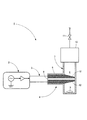
図1に示されるように、本実施形態に係る低エネルギー電磁波反応装置1は、低エネルギー電磁波を反応原料に照射してその反応原料を加熱反応させるものであって、低エネルギー電磁波周波数可変型の低エネルギー電磁波発振ユニット2と、低エネルギー電磁波を反応系に導くための低エネルギー電磁波伝送ユニット3と、反応原料に低エネルギー電磁波を照射する耐圧型の低エネルギー電磁波照射ユニット4とを備えて構成されている。
<Overview of low-energy electromagnetic wave reactor>
As shown in FIG. 1, the low energy electromagnetic
<低エネルギー電磁波発振ユニットの説明>
低エネルギー電磁波発振ユニット2は、0.03〜300GHz帯の全部または一部の帯域の周波数の低エネルギー電磁波を出力するものであって、この低エネルギー電磁波を出力するための低エネルギー電磁波発生器としては、マグネトロン、クライストロン等の発振管方式や各種半導体方式が存在するが、何れの方式を用いることも可能である。但し、出力される低エネルギー電磁波の可変周波数帯域を広く取ることが可能な半導体方式は、特に好ましい。なお、出力される低エネルギー電磁波の周波数の可変帯域は特に限定はされないが、0.5GHz程度以上の帯域幅を出力制御できることが好ましい。
この低エネルギー電磁波発振ユニット2において、可変周波数帯域の中の任意の周波数に設定制御された低エネルギー電磁波は、低エネルギー電磁波伝送ユニット3を通じて低エネルギー電磁波照射ユニット4に伝送される。
<Description of low energy electromagnetic wave oscillation unit>
The low energy electromagnetic
In this low energy electromagnetic
<低エネルギー電磁波伝送ユニットの説明>
低エネルギー電磁波伝送ユニット3は、低エネルギー電磁波発振ユニット2から出力された低エネルギー電磁波を実質的に減衰することなく低エネルギー電磁波照射ユニット4まで伝送できることが肝要であり、そのための伝送路として導波管あるいは同軸線路が一般的である。いずれの伝送方法を用いるかは特に限定されないが、導波管の場合には物理的に伝送不可能となるカットオフ周波数が存在するために伝送できる周波数が限定されるが、同軸線路ではこの制約が無いので低エネルギー電磁波伝送ユニット3として、より好ましい。
<Description of low energy electromagnetic wave transmission unit>
It is important that the low energy electromagnetic wave transmission unit 3 can transmit the low energy electromagnetic wave output from the low energy electromagnetic
<低エネルギー電磁波照射ユニット及び反応原料充填スペースの説明>
低エネルギー電磁波照射ユニット4は、同軸構造をなして水平方向に延びる外部導体5および内部導体6と、鉛直方向に延びる円柱状空間部を有する有底筒体7とが組み合わされて構成されている。
外部導体5および内部導体6は、有底筒体7の底面から適宜上方位置にてその有底筒体7に対し直交布置されている。有底筒体7の円柱状空間部は、反応原料を充填し反応処理するための反応原料充填スペース8とされている。有底筒体7の底部内には、撹拌子9等が配設され、該撹拌子9等を用いた撹拌操作により、反応原料の周方向への偏在を抑止して反応の均一化、定量性が向上可能である。
なお、有底筒体7の上方開口部は、蓋体10によって着脱可能に塞がれ、蓋体10には、耐圧バルブ11が介挿された配管が反応原料充填スペース8に連通可能に接続されている。
<Description of low energy electromagnetic wave irradiation unit and reaction material filling space>
The low-energy electromagnetic
The outer conductor 5 and the
The upper opening of the bottomed
<インピーダンス調整ブロックの説明>
反応原料充填スペース8内に充填された反応原料に対して低エネルギー電磁波照射ユニット4からの低エネルギー電磁波を照射した場合、両者間の物性値差異等に基づく境界面での照射不良(反射率の増大)が生起し易い。そこでこの様な不都合を回避、抑制するために、急激な物性値変化を抑制するための材料および/または形状を有するインピーダンス調整ブロック12を低エネルギー電磁波照射ユニット4における外部導体5と内部導体6との間隙にそれら導体5,6と同軸をなすように布置することが好ましい。これにより、低エネルギー電磁波が円滑に反応原料側に伝送、吸収されることになり、反応原料境界面での反射波の増大等の照射不良が抑制されることになる。
なお、インピーダンス調整ブロック12の構成材料としては、例えば絶縁性材料が好適であり、その形状としては、各導体5,6と同軸をなす円筒状の胴部と、この胴部の先端側に反応原料充填スペース8内に差し込まれる円錐状または半球状の頭部を有する形状のものが好適である。
<Description of impedance adjustment block>
When low energy electromagnetic waves from the low energy electromagnetic
As the constituent material of the
<低エネルギー電磁波照射ユニットでの反応例の説明>
低エネルギー電磁波照射ユニット4から照射された低エネルギー電磁波は、反応原料充填スペース8内の反応原料に照射されることになる。ここで実施される反応の種類は特に限定されることは無く任意である。但し、水あるいは有機溶媒等を用いた各種溶液反応、またはこれらの溶液中に固形物が混在したスラリー反応等は、特に好ましい反応例である。これらの反応においては、低エネルギー電磁波の照射によって温度が上昇すると、溶媒の蒸気圧が上昇して蒸発が活発化する。このような蒸発による溶媒の散逸を抑止するため、反応原料充填スペース8を構成する有底筒体7を含む低エネルギー電磁波照射ユニット4の全体を、耐圧型の気密構造とするのが好ましい。これらの耐圧即ち使用できる最高圧力は例えば1MPa以上で有ることが好ましく、10MPaであれば更に好ましい。
<Description of reaction example in low energy electromagnetic wave irradiation unit>
The low energy electromagnetic wave irradiated from the low energy electromagnetic
反応原料充填スペース8への反応原料充填量は、低エネルギー電磁波照射に際しての照射不良等の不都合を抑止するために、低エネルギー電磁波照射ユニット4の内部導体6が埋没する高さ以上とすることが好ましい。原料充填高さが内部導体6の高さ位置よりも低くなると、照射された低エネルギー電磁波の反射率増大等の不都合が誘因され易くなり、反応効率が低下する。
The amount of reaction raw material charged into the reaction raw
<作用効果の説明>
以上に述べたように構成される低エネルギー電磁波反応装置1においては、低エネルギー電磁波発振ユニット2で0.03〜300GHzの周波数範囲の任意の低エネルギー電磁波が発生、増幅される。ここで発生された低エネルギー電磁波が低エネルギー電磁波伝送ユニット3を通じて低エネルギー電磁波照射ユニット4に伝送される。この低エネルギー電磁波照射ユニット4において、反応原料充填スペース8に充填された反応原料に対して低エネルギー電磁波が照射されることになる。ここで、インピーダンス調整ブロック12の挿入あるいは反応原料の充填高さを低エネルギー電磁波照射ユニット4の内部導体6よりも高位置に維持することによって、低エネルギー電磁波がより効果的に反応原料に照射されることになる。一方、低エネルギー電磁波照射ユニット4における外部導体5および内部導体6が、有底筒体7の底面から適宜上方位置にてその有底筒体に対し直交布置される結果、反応原料充填スペース8の底面での撹拌子9等を用いた撹拌操作が可能となり、反応の均一化、定量性が向上する。
また、反応原料充填スペース8が、鉛直方向に延びる円柱状空間部を有する有底筒体7により形成されるので、反応原料の充填を容易に実施することができるとともに、耐圧性の向上や反応の効率化、安全性の向上等を図ることができる。
<Description of effects>
In the low energy electromagnetic
Moreover, since the reaction raw
以上、本発明の低エネルギー電磁波反応装置について、一実施形態に基づいて説明したが、本発明は上記実施形態に記載した構成に限定されるものではなく、その趣旨を逸脱しない範囲において適宜その構成を変更することができるものである。 As mentioned above, although the low energy electromagnetic wave reaction apparatus of this invention was demonstrated based on one embodiment, this invention is not limited to the structure described in the said embodiment, In the range which does not deviate from the meaning, the structure suitably Can be changed.
次に、本発明による低エネルギー電磁波反応装置の具体的な実施例について、図面を参照しつつ説明する。
図2には、図3に示されるように内径25mmの有底筒体7における反応原料充填スペース8に水を40mmの高さ位置まで充填し、低エネルギー電磁波照射ユニット4における内部導体6と有底筒体7の内壁面との隙間を2mmとして、種々の周波数の低エネルギー電磁波を照射した場合の反射率のシミュレーション結果を示すグラフが示されている。
図2に示されるグラフの縦軸は反射率を示しており、数値が小さいほど反射率が少なく良好であることを表す。ここで、周波数が1.8〜2.7GHzの広帯域で反射率が10%(グラフ中の−10)以下となることを示しており、本発明装置の有効性が確認できる。
Next, specific examples of the low energy electromagnetic wave reaction apparatus according to the present invention will be described with reference to the drawings.
In FIG. 2, as shown in FIG. 3, the reaction raw
The vertical axis of the graph shown in FIG. 2 indicates the reflectance. The smaller the numerical value, the smaller the reflectance and the better. Here, it is shown that the reflectance is 10% (−10 in the graph) or less in a wide frequency band of 1.8 to 2.7 GHz, and the effectiveness of the device of the present invention can be confirmed.
本発明の低エネルギー電磁波反応装置は、幅広い周波数帯の低エネルギー電磁波を反応原料に効果的に照射可能で、しかも反応原料の充填を容易に実施することができるとともに、耐圧性の向上や反応の効率化、安全性の向上等を図ることができるという特徴を有していることから、低エネルギー電磁波加熱による種々の化学反応等の用途に好適に用いることができる。 The low energy electromagnetic wave reaction device of the present invention can effectively irradiate the reaction raw material with low energy electromagnetic waves in a wide frequency band, and can easily carry out the filling of the reaction raw material, while improving the pressure resistance and the reaction. Since it has the feature of being able to improve efficiency, improve safety, etc., it can be suitably used for various chemical reactions and the like by low energy electromagnetic wave heating.
1 低エネルギー電磁波反応装置
2 低エネルギー電磁波発振ユニット
3 低エネルギー電磁波伝送ユニット
4 低エネルギー電磁波照射ユニット
5 外部導体
6 内部導体
7 有底筒体
8 反応原料充填スペース
9 攪拌子
10 蓋体
11 耐圧バルブ
12 インピーダンス調整ブロック
DESCRIPTION OF
Claims (4)
0.03〜300GHz帯の全部または一部の帯域の周波数の低エネルギー電磁波を出力する低エネルギー電磁波周波数可変型の低エネルギー電磁波発振ユニットと、
前記低エネルギー電磁波発振ユニットから出力された低エネルギー電磁波を伝送する低エネルギー電磁波伝送ユニットと、
反応原料を充填するための反応原料充填スペースを有し、この反応原料充填スペースに充填された反応原料に対し、前記低エネルギー電磁波伝送ユニットからの低エネルギー電磁波を照射する低エネルギー電磁波照射ユニットとを備え、
前記反応原料充填スペースを、鉛直方向に延びる円柱状空間部を有する有底筒体により形成したことを特徴とする低エネルギー電磁波反応装置。 A low energy electromagnetic wave reaction device that irradiates a reaction raw material with a low energy electromagnetic wave and heats the reaction raw material,
A low-energy electromagnetic wave frequency variable type low-energy electromagnetic wave oscillation unit that outputs low-energy electromagnetic waves having a frequency in the whole or part of the 0.03-300 GHz band;
A low energy electromagnetic wave transmission unit for transmitting the low energy electromagnetic wave output from the low energy electromagnetic wave oscillation unit;
A low-energy electromagnetic wave irradiation unit for irradiating a low-energy electromagnetic wave from the low-energy electromagnetic wave transmission unit with a reactive raw material filling space for filling the reactive raw material, Prepared,
The low-energy electromagnetic wave reaction apparatus characterized in that the reaction raw material filling space is formed by a bottomed cylindrical body having a cylindrical space portion extending in a vertical direction.
The low energy electromagnetic wave reaction device according to claim 2 or 3, wherein an impedance adjustment block is inserted in a gap between the outer conductor and the inner conductor.
Priority Applications (1)
| Application Number | Priority Date | Filing Date | Title |
|---|---|---|---|
| JP2014061131A JP2015182017A (en) | 2014-03-25 | 2014-03-25 | low-energy electromagnetic wave reactor |
Applications Claiming Priority (1)
| Application Number | Priority Date | Filing Date | Title |
|---|---|---|---|
| JP2014061131A JP2015182017A (en) | 2014-03-25 | 2014-03-25 | low-energy electromagnetic wave reactor |
Publications (1)
| Publication Number | Publication Date |
|---|---|
| JP2015182017A true JP2015182017A (en) | 2015-10-22 |
Family
ID=54349209
Family Applications (1)
| Application Number | Title | Priority Date | Filing Date |
|---|---|---|---|
| JP2014061131A Pending JP2015182017A (en) | 2014-03-25 | 2014-03-25 | low-energy electromagnetic wave reactor |
Country Status (1)
| Country | Link |
|---|---|
| JP (1) | JP2015182017A (en) |
Citations (3)
| Publication number | Priority date | Publication date | Assignee | Title |
|---|---|---|---|---|
| JPS54486A (en) * | 1977-04-08 | 1979-01-05 | Cgr Mev | Device for locally heating living tissue using high frequency electromagnetic wave |
| JPH04305148A (en) * | 1990-07-11 | 1992-10-28 | Internatl Business Mach Corp <Ibm> | Microwave processing method, polymide manufacturing method and microwave apparatus |
| US20070108194A1 (en) * | 2005-10-21 | 2007-05-17 | Matthias Meyer | Microwave autoclave |
-
2014
- 2014-03-25 JP JP2014061131A patent/JP2015182017A/en active Pending
Patent Citations (3)
| Publication number | Priority date | Publication date | Assignee | Title |
|---|---|---|---|---|
| JPS54486A (en) * | 1977-04-08 | 1979-01-05 | Cgr Mev | Device for locally heating living tissue using high frequency electromagnetic wave |
| JPH04305148A (en) * | 1990-07-11 | 1992-10-28 | Internatl Business Mach Corp <Ibm> | Microwave processing method, polymide manufacturing method and microwave apparatus |
| US20070108194A1 (en) * | 2005-10-21 | 2007-05-17 | Matthias Meyer | Microwave autoclave |
Similar Documents
| Publication | Publication Date | Title |
|---|---|---|
| US8969768B2 (en) | Applicator and apparatus for heating samples by microwave radiation | |
| TWI454647B (en) | Microwave heating device | |
| JP6560241B2 (en) | Rapid high pressure microwave pyrolysis system, capsules, and methods for using them | |
| WO2015105080A1 (en) | Chemical reaction device and chemical reaction method | |
| EP2244529B1 (en) | Device for Heating a Sample by Microwave Radiation | |
| CN104470022B (en) | A kind of powder microwave heating equipment and using method thereof | |
| US9833764B2 (en) | Chemical reaction apparatus | |
| KR20100134053A (en) | Device for applying electromagnetic energy to a reactive medium | |
| JP2015142904A (en) | Chemical reaction device and chemical reaction method | |
| JP2015182017A (en) | low-energy electromagnetic wave reactor | |
| JP5531258B2 (en) | Electromagnetic heating device | |
| JP7268854B2 (en) | Microwave processing device, microwave processing method and chemical reaction method | |
| JP5755560B2 (en) | Wireless power supply apparatus and wireless power supply system | |
| JP2010230306A (en) | Heating device with steam generating function | |
| JP6024066B2 (en) | Low energy electromagnetic wave reactor | |
| JP2009100675A (en) | Apparatus for continuously and homogeneously heating food by circularly polarized wave | |
| KR101338141B1 (en) | Microwave Reactor with Microwave Mode Conversion coupler for Chemical Reactor and Method thereof | |
| JP2018055940A (en) | Microwave device and heat treatment system including the same | |
| JP6109994B1 (en) | Heating apparatus, heating method, and program | |
| RU2017107540A (en) | DEVICE FOR PREPARING FOOD FROM USING MICROWAVES | |
| JP2019179649A (en) | Microwave heating device, microwave heating method, and method of manufacturing packaged food | |
| KR100977542B1 (en) | Microwave Reactor with Cavity using Coaxial Waveguide and Method thereof | |
| JP2017037817A (en) | Microwave heating device | |
| JP2007123073A (en) | High-frequency heating device | |
| JP2022024257A (en) | Microwave processor and microwave processing method |
Legal Events
| Date | Code | Title | Description |
|---|---|---|---|
| A621 | Written request for application examination |
Free format text: JAPANESE INTERMEDIATE CODE: A621 Effective date: 20170203 |
|
| A521 | Request for written amendment filed |
Free format text: JAPANESE INTERMEDIATE CODE: A821 Effective date: 20170203 |
|
| A521 | Request for written amendment filed |
Free format text: JAPANESE INTERMEDIATE CODE: A523 Effective date: 20170322 |
|
| A977 | Report on retrieval |
Free format text: JAPANESE INTERMEDIATE CODE: A971007 Effective date: 20170823 |
|
| A131 | Notification of reasons for refusal |
Free format text: JAPANESE INTERMEDIATE CODE: A131 Effective date: 20170829 |
|
| A02 | Decision of refusal |
Free format text: JAPANESE INTERMEDIATE CODE: A02 Effective date: 20180228 |