JP2015181663A - rice cooker - Google Patents
rice cooker Download PDFInfo
- Publication number
- JP2015181663A JP2015181663A JP2014060207A JP2014060207A JP2015181663A JP 2015181663 A JP2015181663 A JP 2015181663A JP 2014060207 A JP2014060207 A JP 2014060207A JP 2014060207 A JP2014060207 A JP 2014060207A JP 2015181663 A JP2015181663 A JP 2015181663A
- Authority
- JP
- Japan
- Prior art keywords
- main body
- handle
- rice cooker
- recesses
- sides
- Prior art date
- Legal status (The legal status is an assumption and is not a legal conclusion. Google has not performed a legal analysis and makes no representation as to the accuracy of the status listed.)
- Granted
Links
Images

Landscapes
- Cookers (AREA)
Abstract
Description
本発明は、本体の底面両側部に手掛け用凹部を備えた炊飯器に関するものである。 The present invention relates to a rice cooker provided with concave portions for handling on both sides of a bottom surface of a main body.
従来の炊飯器において、本体の底面両側部に手掛け用凹部を設けたものがある(例えば、特許文献1参照)。 In a conventional rice cooker, there is a rice cooker provided with concave portions for holding on both sides of the bottom surface of the main body (for example, see Patent Document 1).
近年、炊飯器は、多機能になり、かつ加熱手段にIHコイルを用いるのが主流となっている。そして、このように多機能になり、加熱手段にIHコイルを用いたものにあっては、電源基板やこれに実装された素子によって内部構造が複雑化し、手掛け用凹部を設置したい位置に設けることが難しくなってきている。 In recent years, rice cookers have become multifunctional, and it has become mainstream to use IH coils as heating means. And if it becomes multifunctional in this way and uses an IH coil as the heating means, the internal structure becomes complicated by the power supply board and the elements mounted on it, and the handle recess is provided at the position where it is desired to be installed. Is getting harder.
手掛け用凹部を設置したい位置に設けるためには、その位置に設置スペースを確保する必要があるが、既述したように内部構造が複雑化し、省スペース化は困難なため、手掛け用凹部を設置したい位置に設ける分、本体を大型化せざるを得ない。 In order to install the recessed part for the handle, it is necessary to secure an installation space at that position. However, as described above, the internal structure becomes complicated and space saving is difficult. The main body must be enlarged as much as possible.
本体の大型化を避けるためには、限られたスペースに左右の手掛け用凹部を設置せざるを得ない。その場合、左右の手掛け用凹部は、本体の内部構造の関係で、前後方向でずれた位置に配置せざるを得ない。従って、本体を持ち上げる際に、左右の手掛け用凹部を手探りで探すことになり、使い勝手が悪い。さらに、左右の手掛け用凹部の前後方向のずれによって、左右の手掛け用凹部が本体の重心位置からずれてしまい、持ち運び性が悪くなる。 In order to avoid an increase in the size of the main body, left and right hand recesses must be installed in a limited space. In that case, the left and right hand recesses have to be arranged at positions shifted in the front-rear direction due to the internal structure of the main body. Therefore, when lifting the main body, the left and right hand recesses are searched for, which is inconvenient. In addition, the left and right hand recesses are displaced from the center of gravity of the main body due to the displacement of the left and right hand recesses in the front-rear direction, resulting in poor portability.
本発明は前記のような課題を解決するためになされたもので、本体を大型化することなく、持ち運び性及び使い勝手の良い炊飯器を提供することを目的とする。 The present invention has been made to solve the above-described problems, and an object of the present invention is to provide a rice cooker that is easy to carry and use without increasing the size of the main body.
本発明に係る炊飯器は、本体の下面両側部に、本体を持ち上げるための手掛け用凹部がそれぞれ形成され、これら手掛け用凹部が、本体の前後方向に相対的にずれてなる炊飯器において、本体の下面両側部の手掛け用凹部は、側方から見たこれら手掛け用凹部の投影面内で互いの一部が重なり、これら手掛け用凹部が重なる本体の前後方向の範囲内に本体の重心が位置しており、かつ手掛け用凹部が重なる部位のそれぞれの奥行き方向に延びる側壁が、水平面内で本体の重心側に互いに傾斜して設けられているものである。 In the rice cooker according to the present invention, in the rice cooker in which the concave portions for lifting the main body are respectively formed on both side portions of the lower surface of the main body, and the concave portions for the handle are relatively displaced in the front-rear direction of the main body. The handle recesses on both sides of the lower surface of the body overlap with each other in the projection plane of these handle recesses when viewed from the side, and the center of gravity of the main body is located within the longitudinal range of the body where these handle recesses overlap In addition, the side walls extending in the depth direction of the portions where the handle recesses overlap with each other are provided to be inclined with respect to the center of gravity of the main body in the horizontal plane.
本発明に係る炊飯器において、本体の下面両側部の手掛け用凹部は、側方から見たこれら手掛け用凹部の投影面内で互いの一部が重なり、これら手掛け用凹部が重なる本体の前後方向の範囲内に本体の重心が位置しており、かつ手掛け用凹部が重なる部位のそれぞれの奥行き方向に延びる側壁が、水平面内で本体の重心側に互いに傾斜して設けられているので、両側の手掛け用凹部に手を差し込むと、水平面内で本体の重心側に傾斜している側壁に手指が当たり、本体の重心に近づく方向に案内される。このため、両側の手掛け用凹部が本体の前後方向に相対的にずれて配置されていても、持ち運ぶ際に、手指の位置が本体の重心側から遠ざかるのを抑制することができ、持ち運び性及び使い勝手が良くなる。 In the rice cooker according to the present invention, the recessed portions for the handle on both sides of the lower surface of the main body are partially overlapped with each other in the projection plane of the recessed portions for the handle as viewed from the side, and the front-rear direction of the main body is overlapped with the recessed portions for the handle Since the center of gravity of the main body is located within the range of and the side walls extending in the depth direction of the portions where the concave portions for the handle overlap are inclined to the center of gravity of the main body in the horizontal plane, When a hand is inserted into the handle recess, a finger hits a side wall inclined toward the center of gravity of the main body in a horizontal plane, and is guided in a direction approaching the center of gravity of the main body. For this reason, even if the concave recesses for holding on both sides are arranged relatively displaced in the front-rear direction of the main body, the position of the fingers can be prevented from moving away from the center of gravity of the main body when carrying, Usability is improved.
以下、図示実施形態に基づき本発明を説明する。なお、以下に示す図面の形態によって本発明が限定されるものではない。また、各図において、同一の構成には同一の符号を付している。 Hereinafter, the present invention will be described based on illustrated embodiments. In addition, this invention is not limited by the form of drawing shown below. Moreover, in each figure, the same code | symbol is attached | subjected to the same structure.
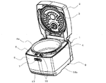
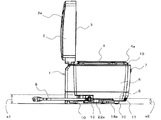
図1は本発明の実施形態に係る炊飯器の蓋体を開いた状態の斜視図である。図2は本発明の実施形態に係る炊飯器の蓋体を開いた状態の側面図である。 FIG. 1 is a perspective view of a rice cooker according to an embodiment of the present invention with a lid opened. FIG. 2 is a side view of the rice cooker according to the embodiment of the present invention with the lid opened.
図1及び図2に示されるように、本実施形態に係る炊飯器の本体1は、底面ケース9と、底面ケース9に載置されて支持された側面ケース6と、側面ケース6にヒンジ機構を介して取り付けられた蓋体2とを備えている。側面ケース6には、上部に開口部を有し、底部にコイル台(図示せず)が固定された樹脂製の内ケース5が備えられており、内ケース5には、内釜4が出し入れ自在に収容される。コイル台の底部外周には、内釜4を電磁誘導加熱する加熱コイル(図示せず)が配置されている。加熱コイルは、電源基板(図示せず)に実装された駆動部によって高周波電力が供給され、内釜4を電磁誘導加熱する。
As shown in FIGS. 1 and 2, the
内釜4は、その上端にフランジ4aが形成され、このフランジ4aが内ケース5への収納時に、内ケース5の開口部の周縁部に載置されて支持される。
The
蓋体2は、図2で示されるように、上面に操作・表示部2aを有するとともに、下面に内蓋3を有しており、本体1の後部側において、内ケース5に回動自在に連結されている。また、蓋体2は、側面ケース6に設けたラッチ19と解除ボタン7とによって開閉される。操作・表示部2aは、内釜4に投入された米等の調理物に対する炊飯工程等を開始させるためのものである。この操作・表示部2aは、使用者によって操作されることによって、操作信号を生成し、その操作信号を本体1内に設置されている制御基板(図示せず)に送信する。また、操作・表示部2aは、炊飯工程の進捗状況の表示、時計表示、及び異常時の異常表示をするものである。
As shown in FIG. 2, the
底面ケース9には、図1及び図2に示されるように、その下面両側部に、本体1を持ち上げるための手掛け用凹部18a,18bがそれぞれ形成されている。また、一方(正面から見て左側)の手掛け用凹部18aに隣接させて、電源コード8のプラグが差し込まれるインレット13が設けられている。また、図2に示されるように、インレット13のコード出口の天面高さa1を、隣接する手掛け用凹部18aの天面高さa2よりも大きく(a1>a2)して異ならせることにより、使用者がインレット13のコード出口付近を持った時、高さが違うことによる違和感を感じさせることで、誤ってコード出口に手を掛けることを防止している。また、底面ケース9には、前縁部に素子冷却用空気の排気口17が設けられているとともに、下方に突出する支持部10が4箇所に設けられている。
As shown in FIGS. 1 and 2, the
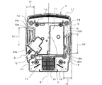
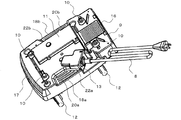
底面ケース9について、図3〜図5に基づき、図1及び図2を参照しながらさらに詳述する。図3は本発明の実施形態に係る炊飯器の下面図であり、図面上の上側部分はこの炊飯器の前部であり、下側部分はこの炊飯器の後部である。図4は本発明の実施形態に係る炊飯器の底面ケースを上下逆向きにして示す斜視図である。図5は本発明の実施形態に係る炊飯器の底面ケースの斜視図である。
The
底面ケース9には、図3及び図4に示されるように、後部に吸気口16が設けられ、この吸気口16の内側に、図5に示されるように、ファン15が設置されている。ファン15によって、吸気口16から外気を導入し、底面ケース9内の加熱コイルや電源基板を冷却し、排気口17から排気される冷却空気の流れを発生させることができる。
As shown in FIGS. 3 and 4, the
ところで、加熱手段にIHコイルを用いた炊飯器は、各種のノイズが発生する。中でもIHコイルは、高周波電圧によって駆動され、一種の高周波発振コイルとして作用するため、その発振に伴うノイズが問題とされる。このノイズが大きいと、制御ユニットのマイコンに影響を与え、誤作動の原因になったり、炊飯器周辺の外部機器(例えばテレビジョンやパソコンなど)にも悪影響を与える。 By the way, the rice cooker using the IH coil as the heating means generates various noises. In particular, the IH coil is driven by a high-frequency voltage and acts as a kind of high-frequency oscillation coil, and noise associated with the oscillation is a problem. If this noise is large, it will affect the microcomputer of the control unit, causing malfunctions, and also adversely affecting external devices (such as televisions and personal computers) around the rice cooker.
そのため、底面ケース9内には、ノイズ対策部品として比較的容量の大きな雑音防止用のコンデンサを搭載したノイズ除去基板11が設けられており、それによってノイズを吸収できるようにしている。
Therefore, the
手掛け用凹部18a,18bは、空きスペースを利用して設置されている。すなわち、手掛け用凹部18a,18bは、図3に示されるように、本体の重心Pを通る前後方向の中心軸線21を挟む両側にて本体1の前後方向に相対的にずれて配置されている。また、側方から見たこれら手掛け用凹部18a,18bの投影面内で互いの一部が重なり、これら手掛け用凹部18a,18bが重なる本体1の前後方向の範囲内に本体の重心Pが位置している。さらに、これら手掛け用凹部18a,18bは、側方から見てこれらが重なる部位のそれぞれの奥行き方向に延びる側壁22a,22bが、手掛け用凹部の奥行き寸法c1,c2の全長に亘り、水平面内で本体の重心P側に互いに傾斜して設けられている。
The
また、手掛け用凹部18aに隣接するインレット13を、手掛け用凹部18aの傾斜に合わせて傾斜させて設置している。
Further, the
また、本体1の下面両側部の手掛け用凹部18a,18bの頂壁には、それぞれ手掛け用凹部内に突出する複数のリブ20a,20bが設けられている。これらのリブ20a,20bは、手掛け用凹部18a,18bに差し込まれた手指の滑り止めとして機能する。
A plurality of
また、底面ケース9には、図4及び図5に示されるように、内ケース5を取り付けるためのねじボス12が4箇所に立設されている。
Further, as shown in FIGS. 4 and 5,
このように、本発明の実施形態に係る炊飯器は、本体1の下面両側部の手掛け用凹部18a,18bにおける側方から見てこれらが重なる部位のそれぞれの奥行き方向に延びる側壁22a,22bが、水平面内で本体の重心P側に互いに傾斜して設けられている。したがって、これら手掛け用凹部18a,18bに手指を差し込むと、本体の重心P側に傾斜している側壁22a,22bに手指が当たり、本体の重心Pに近づく方向に案内される。このため、両側の手掛け用凹部18a,18bが本体1の前後方向に相対的にずれて配置されていても、持ち運ぶ際に、手指の位置が本体の重心P側から遠ざかるのを抑制することができ、持ち運び性及び使い勝手が良くなる。また、両側の手掛け用凹部18a,18bの互いの前後方向の位置を空きスペースを無視して無理矢理合わせるような場合と比べて、本体1を大型化する必要がなくなる。
As described above, the rice cooker according to the embodiment of the present invention includes the
また、本体1の下面両側部の手掛け用凹部18a,18bにおける側方から見てこれらが重なる部位のそれぞれの奥行き方向に延びる側壁22a,22bを、水平面内で本体の重心P側に互いに傾斜して設けることで、手掛け用凹部の間口b1,b2(図3)を容易に広げることができる。このため、手掛け用凹部18a,18bに手探りでも到達し易くなる。
Further, the
また、手掛け用凹部18aに隣接するインレット13を、手掛け用凹部18aの傾斜に合わせて傾斜させて設置しているので、余分なスペースを設ける必要がなくなって、本体1の大型化を抑制することができる。
Further, since the
また、手掛け用凹部18a,18bの頂壁に、滑り止めとして機能する複数のリブ20a,20bを設けているので、手掛け用凹部18a,18bに差し込まれた手指が滑ることがなく、持ち運び性がさらに良くなり、安全性が向上する。
Further, since the plurality of
1 本体、2 蓋体、2a 操作・表示部、3 内蓋、4 内釜、4a フランジ、5 内ケース、6 側面ケース、7 解除ボタン、8 電源コード、9 底面ケース、10 支持部、11 ノイズ除去基板、12 ねじボス、13 インレット、15 ファン、16 吸気口、17 排気口、18a,18b 手掛け用凹部、19 ラッチ、20a,20b リブ、21 中心軸線、22a,22b 側壁、a1 インレットのコード出口の天面高さ、a2 手掛け用凹部の天面高さ、b1,b2 手掛け用凹部の間口、c1,c2 手掛け用凹部の奥行き寸法、P 本体の重心。 1 body, 2 lid, 2a operation / display unit, 3 inner lid, 4 inner hook, 4a flange, 5 inner case, 6 side case, 7 release button, 8 power cord, 9 bottom case, 10 support unit, 11 noise Removal board, 12 Screw boss, 13 Inlet, 15 Fan, 16 Air inlet, 17 Air outlet, 18a, 18b Hand recess, 19 Latch, 20a, 20b Rib, 21 Center axis, 22a, 22b Side wall, a1 Inlet cord outlet The height of the top surface of the recess, a2 The height of the top of the recess for the handle, b1, b2 The opening of the recess for the handle, c1, c2 The depth of the recess for the handle, P The center of gravity of the body.
Claims (3)
前記本体の下面両側部の前記手掛け用凹部は、側方から見たこれら手掛け用凹部の投影面内で互いの一部が重なり、これら手掛け用凹部が重なる前記本体の前後方向の範囲内に前記本体の重心が位置しており、かつ前記手掛け用凹部が重なる部位のそれぞれの奥行き方向に延びる側壁が、水平面内で前記本体の重心側に互いに傾斜して設けられていることを特徴とする炊飯器。 In the rice cooker in which a concave portion for lifting the main body is formed on both sides of the lower surface of the main body, and these concave portions for the handle are relatively displaced in the front-rear direction of the main body,
The recessed portions for the handle on both sides of the lower surface of the main body are partially overlapped with each other in the projection plane of the recessed portions for the handle as viewed from the side, and within the range in the front-rear direction of the main body where the recessed portions for the handle overlap. The rice cooker is characterized in that the center of gravity of the main body is positioned and the side walls extending in the depth direction of the portions where the recesses for hand overlap are inclined to each other toward the center of gravity of the main body in a horizontal plane. vessel.
Priority Applications (1)
| Application Number | Priority Date | Filing Date | Title |
|---|---|---|---|
| JP2014060207A JP6249847B2 (en) | 2014-03-24 | 2014-03-24 | rice cooker |
Applications Claiming Priority (1)
| Application Number | Priority Date | Filing Date | Title |
|---|---|---|---|
| JP2014060207A JP6249847B2 (en) | 2014-03-24 | 2014-03-24 | rice cooker |
Publications (2)
| Publication Number | Publication Date |
|---|---|
| JP2015181663A true JP2015181663A (en) | 2015-10-22 |
| JP6249847B2 JP6249847B2 (en) | 2017-12-20 |
Family
ID=54348930
Family Applications (1)
| Application Number | Title | Priority Date | Filing Date |
|---|---|---|---|
| JP2014060207A Expired - Fee Related JP6249847B2 (en) | 2014-03-24 | 2014-03-24 | rice cooker |
Country Status (1)
| Country | Link |
|---|---|
| JP (1) | JP6249847B2 (en) |
Cited By (1)
| Publication number | Priority date | Publication date | Assignee | Title |
|---|---|---|---|---|
| JP2020171473A (en) * | 2019-04-10 | 2020-10-22 | シャープ株式会社 | Electrical appliance |
Citations (3)
| Publication number | Priority date | Publication date | Assignee | Title |
|---|---|---|---|---|
| JP2004302156A (en) * | 2003-03-31 | 2004-10-28 | Kyocera Mita Corp | Image forming apparatus |
| JP2010046132A (en) * | 2008-08-19 | 2010-03-04 | Mitsubishi Electric Corp | Rice cooker |
| WO2013062064A1 (en) * | 2011-10-27 | 2013-05-02 | 三菱電機株式会社 | Rice cooker |
-
2014
- 2014-03-24 JP JP2014060207A patent/JP6249847B2/en not_active Expired - Fee Related
Patent Citations (3)
| Publication number | Priority date | Publication date | Assignee | Title |
|---|---|---|---|---|
| JP2004302156A (en) * | 2003-03-31 | 2004-10-28 | Kyocera Mita Corp | Image forming apparatus |
| JP2010046132A (en) * | 2008-08-19 | 2010-03-04 | Mitsubishi Electric Corp | Rice cooker |
| WO2013062064A1 (en) * | 2011-10-27 | 2013-05-02 | 三菱電機株式会社 | Rice cooker |
Cited By (1)
| Publication number | Priority date | Publication date | Assignee | Title |
|---|---|---|---|---|
| JP2020171473A (en) * | 2019-04-10 | 2020-10-22 | シャープ株式会社 | Electrical appliance |
Also Published As
| Publication number | Publication date |
|---|---|
| JP6249847B2 (en) | 2017-12-20 |
Similar Documents
| Publication | Publication Date | Title |
|---|---|---|
| JP2022515671A (en) | kitchenware | |
| JP5943775B2 (en) | Electric rice cooker | |
| EP2816290A1 (en) | Heating cooker | |
| TW201618673A (en) | Barbeque stove | |
| JP6249847B2 (en) | rice cooker | |
| JPWO2014112386A1 (en) | Cooker | |
| JP2014084919A (en) | Cam mechanism and heating cooker | |
| CN104879802B (en) | Micro-wave oven | |
| JP5538164B2 (en) | Cooker | |
| JP6456128B2 (en) | Inner pot and rice cooker | |
| JP2016028218A (en) | Support device for cooker, cooker set, and cooker with legs | |
| JP6655930B2 (en) | rice cooker | |
| JP5593861B2 (en) | Electric rice cooker | |
| JP7772610B2 (en) | rice cooker | |
| JP7621291B2 (en) | Rice cooker | |
| JP4957218B2 (en) | Induction heating cooker | |
| JP6678328B2 (en) | rice cooker | |
| KR101014437B1 (en) | Cooker Heater Module | |
| EP4096363A1 (en) | Electric range | |
| CN211673700U (en) | Pot body and cooking utensil having the same | |
| JP6346840B2 (en) | Packing method and cooker set | |
| CN208332347U (en) | Chafing dish electromagnetic stove | |
| JP5425293B2 (en) | Cooker | |
| JP4288606B2 (en) | Built-in cooking device | |
| CN119214463A (en) | Heating Cooker |
Legal Events
| Date | Code | Title | Description |
|---|---|---|---|
| A621 | Written request for application examination |
Free format text: JAPANESE INTERMEDIATE CODE: A621 Effective date: 20160624 |
|
| A131 | Notification of reasons for refusal |
Free format text: JAPANESE INTERMEDIATE CODE: A131 Effective date: 20170321 |
|
| A977 | Report on retrieval |
Free format text: JAPANESE INTERMEDIATE CODE: A971007 Effective date: 20170322 |
|
| A521 | Request for written amendment filed |
Free format text: JAPANESE INTERMEDIATE CODE: A523 Effective date: 20170509 |
|
| TRDD | Decision of grant or rejection written | ||
| A01 | Written decision to grant a patent or to grant a registration (utility model) |
Free format text: JAPANESE INTERMEDIATE CODE: A01 Effective date: 20171024 |
|
| A61 | First payment of annual fees (during grant procedure) |
Free format text: JAPANESE INTERMEDIATE CODE: A61 Effective date: 20171121 |
|
| R150 | Certificate of patent or registration of utility model |
Ref document number: 6249847 Country of ref document: JP Free format text: JAPANESE INTERMEDIATE CODE: R150 |
|
| R250 | Receipt of annual fees |
Free format text: JAPANESE INTERMEDIATE CODE: R250 |
|
| R250 | Receipt of annual fees |
Free format text: JAPANESE INTERMEDIATE CODE: R250 |
|
| R250 | Receipt of annual fees |
Free format text: JAPANESE INTERMEDIATE CODE: R250 |
|
| R250 | Receipt of annual fees |
Free format text: JAPANESE INTERMEDIATE CODE: R250 |
|
| LAPS | Cancellation because of no payment of annual fees |