JP2015178391A - Fluid processing systems and methods - Google Patents
Fluid processing systems and methods Download PDFInfo
- Publication number
- JP2015178391A JP2015178391A JP2015124836A JP2015124836A JP2015178391A JP 2015178391 A JP2015178391 A JP 2015178391A JP 2015124836 A JP2015124836 A JP 2015124836A JP 2015124836 A JP2015124836 A JP 2015124836A JP 2015178391 A JP2015178391 A JP 2015178391A
- Authority
- JP
- Japan
- Prior art keywords
- feed
- flow
- liner
- controllers
- flow controllers
- Prior art date
- Legal status (The legal status is an assumption and is not a legal conclusion. Google has not performed a legal analysis and makes no representation as to the accuracy of the status listed.)
- Granted
Links
- 238000000034 method Methods 0.000 title claims abstract description 88
- 239000012530 fluid Substances 0.000 title claims abstract description 60
- 238000012545 processing Methods 0.000 title description 6
- 239000000463 material Substances 0.000 claims abstract description 160
- 239000000203 mixture Substances 0.000 claims abstract description 70
- 238000002156 mixing Methods 0.000 claims abstract description 59
- 230000008569 process Effects 0.000 claims abstract description 36
- 238000009826 distribution Methods 0.000 claims description 62
- 239000000126 substance Substances 0.000 claims description 47
- XLYOFNOQVPJJNP-UHFFFAOYSA-N water Substances O XLYOFNOQVPJJNP-UHFFFAOYSA-N 0.000 claims description 29
- 238000004891 communication Methods 0.000 claims description 27
- MHAJPDPJQMAIIY-UHFFFAOYSA-N Hydrogen peroxide Chemical compound OO MHAJPDPJQMAIIY-UHFFFAOYSA-N 0.000 claims description 23
- 238000004519 manufacturing process Methods 0.000 claims description 23
- 230000010354 integration Effects 0.000 claims description 16
- 230000003068 static effect Effects 0.000 claims description 6
- 230000004044 response Effects 0.000 claims description 4
- 229920006254 polymer film Polymers 0.000 claims description 3
- 238000009472 formulation Methods 0.000 abstract description 22
- 238000003860 storage Methods 0.000 abstract description 11
- 238000004140 cleaning Methods 0.000 abstract description 6
- 238000012360 testing method Methods 0.000 abstract description 4
- 239000002699 waste material Substances 0.000 abstract description 3
- 239000000470 constituent Substances 0.000 abstract 1
- 238000013341 scale-up Methods 0.000 abstract 1
- 239000007788 liquid Substances 0.000 description 21
- 239000007789 gas Substances 0.000 description 17
- 238000012546 transfer Methods 0.000 description 14
- 239000000047 product Substances 0.000 description 11
- -1 polytetrafluoroethylene Polymers 0.000 description 10
- 238000010586 diagram Methods 0.000 description 9
- 238000004364 calculation method Methods 0.000 description 7
- 238000011049 filling Methods 0.000 description 7
- 238000004377 microelectronic Methods 0.000 description 7
- 238000000605 extraction Methods 0.000 description 6
- 229920001343 polytetrafluoroethylene Polymers 0.000 description 6
- 239000004810 polytetrafluoroethylene Substances 0.000 description 6
- 238000007689 inspection Methods 0.000 description 5
- 238000004806 packaging method and process Methods 0.000 description 5
- 239000002245 particle Substances 0.000 description 5
- 239000004065 semiconductor Substances 0.000 description 5
- 230000002411 adverse Effects 0.000 description 4
- 238000005259 measurement Methods 0.000 description 4
- 239000002243 precursor Substances 0.000 description 4
- 238000004448 titration Methods 0.000 description 4
- RYGMFSIKBFXOCR-UHFFFAOYSA-N Copper Chemical compound [Cu] RYGMFSIKBFXOCR-UHFFFAOYSA-N 0.000 description 3
- 238000011109 contamination Methods 0.000 description 3
- 229910052802 copper Inorganic materials 0.000 description 3
- 239000010949 copper Substances 0.000 description 3
- 239000003814 drug Substances 0.000 description 3
- 229940079593 drug Drugs 0.000 description 3
- 230000002441 reversible effect Effects 0.000 description 3
- 239000004698 Polyethylene Substances 0.000 description 2
- 239000004743 Polypropylene Substances 0.000 description 2
- 230000009471 action Effects 0.000 description 2
- 238000013019 agitation Methods 0.000 description 2
- 230000008901 benefit Effects 0.000 description 2
- 230000015556 catabolic process Effects 0.000 description 2
- 230000008859 change Effects 0.000 description 2
- 238000013329 compounding Methods 0.000 description 2
- 239000000356 contaminant Substances 0.000 description 2
- 230000006837 decompression Effects 0.000 description 2
- 238000006731 degradation reaction Methods 0.000 description 2
- 230000007613 environmental effect Effects 0.000 description 2
- 239000010408 film Substances 0.000 description 2
- 230000009969 flowable effect Effects 0.000 description 2
- 239000011888 foil Substances 0.000 description 2
- 229920001903 high density polyethylene Polymers 0.000 description 2
- 239000004700 high-density polyethylene Substances 0.000 description 2
- 239000012535 impurity Substances 0.000 description 2
- 239000010410 layer Substances 0.000 description 2
- 239000004973 liquid crystal related substance Substances 0.000 description 2
- 239000011344 liquid material Substances 0.000 description 2
- 239000002184 metal Substances 0.000 description 2
- 229910052751 metal Inorganic materials 0.000 description 2
- 238000012986 modification Methods 0.000 description 2
- 230000004048 modification Effects 0.000 description 2
- 239000000049 pigment Substances 0.000 description 2
- 229920000728 polyester Polymers 0.000 description 2
- 229920000573 polyethylene Polymers 0.000 description 2
- 229920000642 polymer Polymers 0.000 description 2
- 229920001155 polypropylene Polymers 0.000 description 2
- 229920002635 polyurethane Polymers 0.000 description 2
- 239000004814 polyurethane Substances 0.000 description 2
- 239000002994 raw material Substances 0.000 description 2
- 239000000523 sample Substances 0.000 description 2
- 229930182556 Polyacetal Natural products 0.000 description 1
- 239000004952 Polyamide Substances 0.000 description 1
- 239000004793 Polystyrene Substances 0.000 description 1
- 229920001328 Polyvinylidene chloride Polymers 0.000 description 1
- OMOVVBIIQSXZSZ-UHFFFAOYSA-N [6-(4-acetyloxy-5,9a-dimethyl-2,7-dioxo-4,5a,6,9-tetrahydro-3h-pyrano[3,4-b]oxepin-5-yl)-5-formyloxy-3-(furan-3-yl)-3a-methyl-7-methylidene-1a,2,3,4,5,6-hexahydroindeno[1,7a-b]oxiren-4-yl] 2-hydroxy-3-methylpentanoate Chemical compound CC12C(OC(=O)C(O)C(C)CC)C(OC=O)C(C3(C)C(CC(=O)OC4(C)COC(=O)CC43)OC(C)=O)C(=C)C32OC3CC1C=1C=COC=1 OMOVVBIIQSXZSZ-UHFFFAOYSA-N 0.000 description 1
- 239000000654 additive Substances 0.000 description 1
- 230000032683 aging Effects 0.000 description 1
- 239000003570 air Substances 0.000 description 1
- 230000004888 barrier function Effects 0.000 description 1
- 235000013361 beverage Nutrition 0.000 description 1
- 230000015572 biosynthetic process Effects 0.000 description 1
- 238000009530 blood pressure measurement Methods 0.000 description 1
- 238000009388 chemical precipitation Methods 0.000 description 1
- 238000012824 chemical production Methods 0.000 description 1
- 238000006243 chemical reaction Methods 0.000 description 1
- 239000007795 chemical reaction product Substances 0.000 description 1
- 239000003153 chemical reaction reagent Substances 0.000 description 1
- 239000003795 chemical substances by application Substances 0.000 description 1
- 238000005229 chemical vapour deposition Methods 0.000 description 1
- 239000002131 composite material Substances 0.000 description 1
- 239000004035 construction material Substances 0.000 description 1
- 229920001577 copolymer Polymers 0.000 description 1
- 230000008878 coupling Effects 0.000 description 1
- 238000010168 coupling process Methods 0.000 description 1
- 238000005859 coupling reaction Methods 0.000 description 1
- 239000008367 deionised water Substances 0.000 description 1
- 229910021641 deionized water Inorganic materials 0.000 description 1
- 238000007599 discharging Methods 0.000 description 1
- 238000011143 downstream manufacturing Methods 0.000 description 1
- 238000005516 engineering process Methods 0.000 description 1
- 238000001125 extrusion Methods 0.000 description 1
- 238000005429 filling process Methods 0.000 description 1
- 238000001914 filtration Methods 0.000 description 1
- 239000012467 final product Substances 0.000 description 1
- 239000011521 glass Substances 0.000 description 1
- 230000005484 gravity Effects 0.000 description 1
- 231100001261 hazardous Toxicity 0.000 description 1
- QOSATHPSBFQAML-UHFFFAOYSA-N hydrogen peroxide;hydrate Chemical compound O.OO QOSATHPSBFQAML-UHFFFAOYSA-N 0.000 description 1
- 238000010348 incorporation Methods 0.000 description 1
- 239000003112 inhibitor Substances 0.000 description 1
- 239000005001 laminate film Substances 0.000 description 1
- 229920001684 low density polyethylene Polymers 0.000 description 1
- 239000004702 low-density polyethylene Substances 0.000 description 1
- 238000012423 maintenance Methods 0.000 description 1
- 238000007620 mathematical function Methods 0.000 description 1
- 239000011104 metalized film Substances 0.000 description 1
- 238000010943 off-gassing Methods 0.000 description 1
- 238000005457 optimization Methods 0.000 description 1
- 239000012466 permeate Substances 0.000 description 1
- 239000000825 pharmaceutical preparation Substances 0.000 description 1
- 229940127557 pharmaceutical product Drugs 0.000 description 1
- 229920002120 photoresistant polymer Polymers 0.000 description 1
- 229920002239 polyacrylonitrile Polymers 0.000 description 1
- 229920002647 polyamide Polymers 0.000 description 1
- 229920001748 polybutylene Polymers 0.000 description 1
- 229920006324 polyoxymethylene Polymers 0.000 description 1
- 229920002223 polystyrene Polymers 0.000 description 1
- 229920000915 polyvinyl chloride Polymers 0.000 description 1
- 239000004800 polyvinyl chloride Substances 0.000 description 1
- 239000005033 polyvinylidene chloride Substances 0.000 description 1
- 238000002310 reflectometry Methods 0.000 description 1
- 238000007789 sealing Methods 0.000 description 1
- 239000002356 single layer Substances 0.000 description 1
- 239000002002 slurry Substances 0.000 description 1
- 239000007787 solid Substances 0.000 description 1
- 239000008247 solid mixture Substances 0.000 description 1
- 239000002904 solvent Substances 0.000 description 1
- 229910001220 stainless steel Inorganic materials 0.000 description 1
- 239000010935 stainless steel Substances 0.000 description 1
- 238000003756 stirring Methods 0.000 description 1
- 239000000758 substrate Substances 0.000 description 1
- 231100000331 toxic Toxicity 0.000 description 1
- 230000002588 toxic effect Effects 0.000 description 1
- 238000013022 venting Methods 0.000 description 1
Images


Classifications
-
- H—ELECTRICITY
- H01—ELECTRIC ELEMENTS
- H01L—SEMICONDUCTOR DEVICES NOT COVERED BY CLASS H10
- H01L21/00—Processes or apparatus adapted for the manufacture or treatment of semiconductor or solid state devices or of parts thereof
- H01L21/02—Manufacture or treatment of semiconductor devices or of parts thereof
- H01L21/02041—Cleaning
- H01L21/02043—Cleaning before device manufacture, i.e. Begin-Of-Line process
- H01L21/02052—Wet cleaning only
-
- B—PERFORMING OPERATIONS; TRANSPORTING
- B01—PHYSICAL OR CHEMICAL PROCESSES OR APPARATUS IN GENERAL
- B01F—MIXING, e.g. DISSOLVING, EMULSIFYING OR DISPERSING
- B01F23/00—Mixing according to the phases to be mixed, e.g. dispersing or emulsifying
- B01F23/40—Mixing liquids with liquids; Emulsifying
- B01F23/45—Mixing liquids with liquids; Emulsifying using flow mixing
-
- B—PERFORMING OPERATIONS; TRANSPORTING
- B01—PHYSICAL OR CHEMICAL PROCESSES OR APPARATUS IN GENERAL
- B01F—MIXING, e.g. DISSOLVING, EMULSIFYING OR DISPERSING
- B01F23/00—Mixing according to the phases to be mixed, e.g. dispersing or emulsifying
- B01F23/40—Mixing liquids with liquids; Emulsifying
- B01F23/48—Mixing liquids with liquids; Emulsifying characterised by the nature of the liquids
- B01F23/483—Mixing liquids with liquids; Emulsifying characterised by the nature of the liquids using water for diluting a liquid ingredient, obtaining a predetermined concentration or making an aqueous solution of a concentrate
-
- B—PERFORMING OPERATIONS; TRANSPORTING
- B01—PHYSICAL OR CHEMICAL PROCESSES OR APPARATUS IN GENERAL
- B01F—MIXING, e.g. DISSOLVING, EMULSIFYING OR DISPERSING
- B01F35/00—Accessories for mixers; Auxiliary operations or auxiliary devices; Parts or details of general application
- B01F35/71—Feed mechanisms
- B01F35/712—Feed mechanisms for feeding fluids
-
- B—PERFORMING OPERATIONS; TRANSPORTING
- B01—PHYSICAL OR CHEMICAL PROCESSES OR APPARATUS IN GENERAL
- B01F—MIXING, e.g. DISSOLVING, EMULSIFYING OR DISPERSING
- B01F35/00—Accessories for mixers; Auxiliary operations or auxiliary devices; Parts or details of general application
- B01F35/71—Feed mechanisms
- B01F35/717—Feed mechanisms characterised by the means for feeding the components to the mixer
- B01F35/71745—Feed mechanisms characterised by the means for feeding the components to the mixer using pneumatic pressure, overpressure, gas or air pressure in a closed receptacle or circuit system
-
- B—PERFORMING OPERATIONS; TRANSPORTING
- B01—PHYSICAL OR CHEMICAL PROCESSES OR APPARATUS IN GENERAL
- B01F—MIXING, e.g. DISSOLVING, EMULSIFYING OR DISPERSING
- B01F35/00—Accessories for mixers; Auxiliary operations or auxiliary devices; Parts or details of general application
- B01F35/71—Feed mechanisms
- B01F35/717—Feed mechanisms characterised by the means for feeding the components to the mixer
- B01F35/71795—Squeezing a flexible container
-
- B—PERFORMING OPERATIONS; TRANSPORTING
- B01—PHYSICAL OR CHEMICAL PROCESSES OR APPARATUS IN GENERAL
- B01F—MIXING, e.g. DISSOLVING, EMULSIFYING OR DISPERSING
- B01F35/00—Accessories for mixers; Auxiliary operations or auxiliary devices; Parts or details of general application
- B01F35/71—Feed mechanisms
- B01F35/717—Feed mechanisms characterised by the means for feeding the components to the mixer
- B01F35/718—Feed mechanisms characterised by the means for feeding the components to the mixer using vacuum, under pressure in a closed receptacle or circuit system
-
- B—PERFORMING OPERATIONS; TRANSPORTING
- B65—CONVEYING; PACKING; STORING; HANDLING THIN OR FILAMENTARY MATERIAL
- B65B—MACHINES, APPARATUS OR DEVICES FOR, OR METHODS OF, PACKAGING ARTICLES OR MATERIALS; UNPACKING
- B65B3/00—Packaging plastic material, semiliquids, liquids or mixed solids and liquids, in individual containers or receptacles, e.g. bags, sacks, boxes, cartons, cans, or jars
- B65B3/04—Methods of, or means for, filling the material into the containers or receptacles
- B65B3/10—Methods of, or means for, filling the material into the containers or receptacles by application of pressure to material
- B65B3/14—Methods of, or means for, filling the material into the containers or receptacles by application of pressure to material pneumatically
-
- B—PERFORMING OPERATIONS; TRANSPORTING
- B67—OPENING, CLOSING OR CLEANING BOTTLES, JARS OR SIMILAR CONTAINERS; LIQUID HANDLING
- B67D—DISPENSING, DELIVERING OR TRANSFERRING LIQUIDS, NOT OTHERWISE PROVIDED FOR
- B67D7/00—Apparatus or devices for transferring liquids from bulk storage containers or reservoirs into vehicles or into portable containers, e.g. for retail sale purposes
- B67D7/02—Apparatus or devices for transferring liquids from bulk storage containers or reservoirs into vehicles or into portable containers, e.g. for retail sale purposes for transferring liquids other than fuel or lubricants
- B67D7/0238—Apparatus or devices for transferring liquids from bulk storage containers or reservoirs into vehicles or into portable containers, e.g. for retail sale purposes for transferring liquids other than fuel or lubricants utilising compressed air or other gas acting directly or indirectly on liquids in storage containers
- B67D7/0244—Apparatus or devices for transferring liquids from bulk storage containers or reservoirs into vehicles or into portable containers, e.g. for retail sale purposes for transferring liquids other than fuel or lubricants utilising compressed air or other gas acting directly or indirectly on liquids in storage containers by using elastic expandable bags
- B67D7/025—Apparatus or devices for transferring liquids from bulk storage containers or reservoirs into vehicles or into portable containers, e.g. for retail sale purposes for transferring liquids other than fuel or lubricants utilising compressed air or other gas acting directly or indirectly on liquids in storage containers by using elastic expandable bags specially adapted for transferring liquids of high purity
-
- B—PERFORMING OPERATIONS; TRANSPORTING
- B67—OPENING, CLOSING OR CLEANING BOTTLES, JARS OR SIMILAR CONTAINERS; LIQUID HANDLING
- B67D—DISPENSING, DELIVERING OR TRANSFERRING LIQUIDS, NOT OTHERWISE PROVIDED FOR
- B67D7/00—Apparatus or devices for transferring liquids from bulk storage containers or reservoirs into vehicles or into portable containers, e.g. for retail sale purposes
- B67D7/02—Apparatus or devices for transferring liquids from bulk storage containers or reservoirs into vehicles or into portable containers, e.g. for retail sale purposes for transferring liquids other than fuel or lubricants
- B67D7/0238—Apparatus or devices for transferring liquids from bulk storage containers or reservoirs into vehicles or into portable containers, e.g. for retail sale purposes for transferring liquids other than fuel or lubricants utilising compressed air or other gas acting directly or indirectly on liquids in storage containers
- B67D7/0255—Apparatus or devices for transferring liquids from bulk storage containers or reservoirs into vehicles or into portable containers, e.g. for retail sale purposes for transferring liquids other than fuel or lubricants utilising compressed air or other gas acting directly or indirectly on liquids in storage containers squeezing collapsible or flexible storage containers
- B67D7/0261—Apparatus or devices for transferring liquids from bulk storage containers or reservoirs into vehicles or into portable containers, e.g. for retail sale purposes for transferring liquids other than fuel or lubricants utilising compressed air or other gas acting directly or indirectly on liquids in storage containers squeezing collapsible or flexible storage containers specially adapted for transferring liquids of high purity
-
- B—PERFORMING OPERATIONS; TRANSPORTING
- B67—OPENING, CLOSING OR CLEANING BOTTLES, JARS OR SIMILAR CONTAINERS; LIQUID HANDLING
- B67D—DISPENSING, DELIVERING OR TRANSFERRING LIQUIDS, NOT OTHERWISE PROVIDED FOR
- B67D7/00—Apparatus or devices for transferring liquids from bulk storage containers or reservoirs into vehicles or into portable containers, e.g. for retail sale purposes
- B67D7/02—Apparatus or devices for transferring liquids from bulk storage containers or reservoirs into vehicles or into portable containers, e.g. for retail sale purposes for transferring liquids other than fuel or lubricants
- B67D7/0277—Apparatus or devices for transferring liquids from bulk storage containers or reservoirs into vehicles or into portable containers, e.g. for retail sale purposes for transferring liquids other than fuel or lubricants using negative pressure
- B67D7/0283—Apparatus or devices for transferring liquids from bulk storage containers or reservoirs into vehicles or into portable containers, e.g. for retail sale purposes for transferring liquids other than fuel or lubricants using negative pressure specially adapted for transferring liquids of high purity
-
- B—PERFORMING OPERATIONS; TRANSPORTING
- B67—OPENING, CLOSING OR CLEANING BOTTLES, JARS OR SIMILAR CONTAINERS; LIQUID HANDLING
- B67D—DISPENSING, DELIVERING OR TRANSFERRING LIQUIDS, NOT OTHERWISE PROVIDED FOR
- B67D7/00—Apparatus or devices for transferring liquids from bulk storage containers or reservoirs into vehicles or into portable containers, e.g. for retail sale purposes
- B67D7/06—Details or accessories
- B67D7/74—Devices for mixing two or more different liquids to be transferred
- B67D7/741—Devices for mixing two or more different liquids to be transferred mechanically operated
-
- H—ELECTRICITY
- H01—ELECTRIC ELEMENTS
- H01L—SEMICONDUCTOR DEVICES NOT COVERED BY CLASS H10
- H01L21/00—Processes or apparatus adapted for the manufacture or treatment of semiconductor or solid state devices or of parts thereof
- H01L21/02—Manufacture or treatment of semiconductor devices or of parts thereof
- H01L21/027—Making masks on semiconductor bodies for further photolithographic processing not provided for in group H01L21/18 or H01L21/34
- H01L21/0271—Making masks on semiconductor bodies for further photolithographic processing not provided for in group H01L21/18 or H01L21/34 comprising organic layers
- H01L21/0273—Making masks on semiconductor bodies for further photolithographic processing not provided for in group H01L21/18 or H01L21/34 comprising organic layers characterised by the treatment of photoresist layers
-
- H—ELECTRICITY
- H01—ELECTRIC ELEMENTS
- H01L—SEMICONDUCTOR DEVICES NOT COVERED BY CLASS H10
- H01L21/00—Processes or apparatus adapted for the manufacture or treatment of semiconductor or solid state devices or of parts thereof
- H01L21/02—Manufacture or treatment of semiconductor devices or of parts thereof
- H01L21/04—Manufacture or treatment of semiconductor devices or of parts thereof the devices having at least one potential-jump barrier or surface barrier, e.g. PN junction, depletion layer or carrier concentration layer
- H01L21/18—Manufacture or treatment of semiconductor devices or of parts thereof the devices having at least one potential-jump barrier or surface barrier, e.g. PN junction, depletion layer or carrier concentration layer the devices having semiconductor bodies comprising elements of Group IV of the Periodic System or AIIIBV compounds with or without impurities, e.g. doping materials
- H01L21/30—Treatment of semiconductor bodies using processes or apparatus not provided for in groups H01L21/20 - H01L21/26
- H01L21/302—Treatment of semiconductor bodies using processes or apparatus not provided for in groups H01L21/20 - H01L21/26 to change their surface-physical characteristics or shape, e.g. etching, polishing, cutting
- H01L21/304—Mechanical treatment, e.g. grinding, polishing, cutting
Abstract
Description
(関連出願の相互参照)
[0001] 本出願は、参照により本明細書に組み込むものとする2009年6月10日出願の米国仮特許出願第61/185,817号の優先権を主張する。
(Cross-reference of related applications)
[0001] This application claims priority to US Provisional Patent Application No. 61 / 185,817, filed June 10, 2009, which is incorporated herein by reference.
[0002] 本発明は、流体を利用するプロセスに対し、流体を含有するプロセス材料を送出するシステム及び方法に関する。プロセスには、半導体及びマイクロ電子デバイスの製造、及びこのようなシステム及び方法を組み込んだ生成物の製造に採用されるプロセスが含まれる(しかし、これらに限定されない)。 [0002] The present invention relates to a system and method for delivering a process material containing a fluid to a process that utilizes the fluid. Processes include (but are not limited to) processes employed in the manufacture of semiconductor and microelectronic devices, and products incorporating such systems and methods.
[0003] プロセス機器(例えばプロセスツール)への流体含有供給材料の送出は、様々な製造プロセスで日常的に実行されている。多くの産業で、供給材料を超高純度の形態且つ実質的に汚染物質がない状態で提供することが必要である。この文脈で「供給材料」という用語は、広義に製造及び/又は産業プロセスで使用又は消費される様々な材料のいずれかを指す。 [0003] Delivery of fluid-containing feed materials to process equipment (eg, process tools) is routinely performed in various manufacturing processes. In many industries, it is necessary to provide feed materials in ultra high purity form and substantially free of contaminants. The term “feed material” in this context refers broadly to any of a variety of materials used or consumed in manufacturing and / or industrial processes.
[0004] 半導体、マイクロ電子デバイス及び/又は構成部品又はその前駆体を製造する状況で、特定の汚染物質が少量でも存在すると、その結果の生成物がその意図された目的にとって不完全に、又は無用にさえなってしまうことがある。したがって、このような製造機器に供給材料を供給するために使用される送出システム(例えば容器及び送出構成部品を含む)は、汚染問題を回避する性質でなければならない。材料送出容器は、脱粒、アウトガス、及び任意の他の形態で容器及び送出構成部品からそれに封じ込められるか他の方法でそれと接触状態で配置された供給材料へと汚染物質が付与されることを回避しながら、厳密に清浄な状態でなければならない。供給材料が紫外線、熱、環境ガス、プロセスガス、破片及び不純物に曝露すると、このような材料に悪影響を及ぼすことがあるので、材料送出システムは、封じ込められた材料が劣化又は分解することなく、供給材料を純粋な状態に維持すべきことが望ましい。特定の供給材料は、望ましくない方法(例えば化学反応又は析出)で相互作用することがあり、したがってこのような構成成分の組合せ保存は回避しなければならない。純粋な供給材料は極めて高価なことがあるので、このような材料の浪費は最小限にしなければならない。有毒及び/又は危険な供給材料への曝露も回避すべきである。 [0004] In the context of manufacturing semiconductors, microelectronic devices and / or components or precursors thereof, the presence of even a small amount of a particular contaminant results in an incomplete product for its intended purpose, or It can even become useless. Accordingly, the delivery system (including containers and delivery components) used to supply feed to such manufacturing equipment must be of a nature that avoids contamination problems. The material delivery container avoids spilling, outgassing, and any other form of contamination from the container and delivery components to the feed material that is contained or otherwise placed in contact therewith. While it must be strictly clean. Because the feed material is exposed to ultraviolet light, heat, environmental gases, process gases, debris and impurities, such materials may be adversely affected, so the material delivery system will not degrade or degrade the contained material, It is desirable to keep the feed material pure. Certain feed materials may interact in undesired ways (eg, chemical reaction or precipitation), and thus such component combination storage must be avoided. Since pure feed materials can be very expensive, the waste of such materials must be minimized. Exposure to toxic and / or hazardous feedstocks should also be avoided.
[0005] これらの考慮事項の結果、フォトレジスト、エッチング液、化学蒸着試薬、溶媒、ウェーハ及びツール洗浄配合物、化学的機械的平坦化(CMP)用組成物、カラーフィルタリング用化学物質、オーバコート、液晶材料などのようなマイクロ電子デバイスの製造に使用される液体及び液体含有組成物のために、多種の高純度パッケージングが開発されている。特定の用途には反応性流体を使用することができ、複数の異なる流体を含む組成物及び/又は流体と固体の組成物が有用なことがある。 [0005] As a result of these considerations, photoresists, etchants, chemical vapor deposition reagents, solvents, wafer and tool cleaning formulations, chemical mechanical planarization (CMP) compositions, color filtering chemicals, overcoats A variety of high purity packaging has been developed for liquids and liquid-containing compositions used in the manufacture of microelectronic devices such as liquid crystal materials. For certain applications, reactive fluids can be used, and compositions comprising a plurality of different fluids and / or fluid and solid compositions may be useful.
[0006] このように使用されている高純度パッケージングのうち1つのタイプは剛性又は半剛性のオーバーパックを含み、これは蓋又はカバーのような保持構造によってオーバーパック内の所定の位置に固定された可撓性ライナ又はバッグに入った液体又は液体状組成物を封じ込める。このようなパッケージングを一般的に、「バッグインカン」(BIC)、「バッグインボトル」(BIB)及び「バッグインドラム」(BID)と呼ぶ。このような一般的タイプのパッケージングが、ATMI, Inc.(米国コネチカット州ダンベリ)からNOWPAKという商標で市販されている。ライナは可撓性材料を備え、オーバーパック容器は、上記可撓性材料よりも有意に剛性である壁材料を備えることが好ましい。パッケージングの剛性又は半剛性オーバーパックは、例えば高密度ポリエチレン又は他のポリマー又は金属で形成することができ、ライナは、予備洗浄し、ポリテトラフルオロエチレン(PTFE)、低密度ポリエチレン、PTFE系多層積層材、ポリアミド、ポリエステル、ポリウレタンなどのようなポリマー材料を含み、ライナ内に封じ込められる液体又は液体系材料に対して不活性であるように選択された1層又は多層積層フィルム材料の無菌折り畳み式バッグとして提供することができる。ライナ構造の例示的材料はさらに、金属化フィルム、箔、ポリマー/コポリマー、積層材、押出し成形品、共押出し成形品、及び吹込及び流延フィルムを含む。 [0006] One type of high purity packaging used in this way includes a rigid or semi-rigid overpack, which is secured in place within the overpack by a retaining structure such as a lid or cover. Contain a liquid or liquid composition contained in a molded flexible liner or bag. Such packaging is generally referred to as “bag in can” (BIC), “bag in bottle” (BIB), and “bag in drum” (BID). Such a general type of packaging is commercially available from ATMI, Inc. (Dumbury, CT, USA) under the trademark NOWWPAK. Preferably, the liner comprises a flexible material and the overpack container comprises a wall material that is significantly more rigid than the flexible material. The packaging rigid or semi-rigid overpack can be made of, for example, high density polyethylene or other polymer or metal, the liner is pre-cleaned, polytetrafluoroethylene (PTFE), low density polyethylene, PTFE based multilayer Sterile foldable of single-layer or multi-layer laminate film materials selected to be inert to liquid or liquid-based materials that are contained within a liner, including polymeric materials such as laminates, polyamides, polyesters, polyurethanes, etc. Can be provided as a bag. Exemplary liner construction materials further include metallized films, foils, polymers / copolymers, laminates, extrusions, coextrusions, and blown and cast films.
[0007] 液体及び液体状組成物の特定のライナ系パッケージを含む分配作業では、分配アセンブリ(任意選択で封じ込められた液体に浸漬される浸漬管又は短いプローブを含む)をライナのポートに接続することによって、ライナから内容物を分配することができる。このように分配アセンブリをライナに結合した後、ライナの外表面に流体(例えば気体)圧が加えられ、したがって、これは漸進的に折り畳まれ、最終使用場所へと流すために関連した流回路へと放出する圧力分配により、強制的に液体を分配アセンブリに通す。 [0007] In dispensing operations involving specific liner-based packages of liquids and liquid compositions, a dispensing assembly (including a dip tube or short probe that is optionally immersed in an enclosed liquid) is connected to the port of the liner. The contents can be distributed from the liner. After coupling the dispensing assembly to the liner in this manner, fluid (e.g., gas) pressure is applied to the outer surface of the liner so that it is progressively folded into the associated flow circuit for flow to the end-use location. And the pressure distribution that discharges forces the liquid through the distribution assembly.
[0008] 圧力分配パッケージの使用に付随する問題は、封じ込められた液体に気体が浸透又は漏入し、液体中に可溶化して気泡が形成されることである。ライナ系パッケージの場合、ライナとオーバーパックの間にある加圧気体がライナを通って封じ込められた液体中に浸透し、そこでこのような気体が溶解することがある。その後に液体を分配すると、分配ライン及び下流の計器及び機器内の圧力が低下して、以前に溶解した気体を放出させ、その結果、分配される液体の細流に気泡が形成されて、下流のプロセスに悪影響を及ぼすことがある。したがって、ライナ系分配容器内で封じ込められた流体内へのヘッドスペースガスの移動を最小化することが望ましい。 [0008] A problem associated with the use of pressure distribution packages is that gas penetrates or leaks into the contained liquid and is solubilized in the liquid to form bubbles. In the case of liner-based packages, the pressurized gas between the liner and the overpack can permeate through the liner and into the confined liquid, where such gas can dissolve. Subsequent dispensing of liquid reduces the pressure in the dispensing line and downstream instruments and equipment, releasing the previously dissolved gas, resulting in the formation of bubbles in the stream of liquid being dispensed, and the downstream May adversely affect the process. Accordingly, it is desirable to minimize headspace gas movement into the fluid contained within the liner-based distribution container.
[0009] 所望の流量が広範囲に変動する流体を分配する場合、流量制御の正確さ又は精度を犠牲にせずに、望ましい広範囲の流れを提供することが困難になることがある。広範囲の望ましい流量にわたって、1つ又は複数の流体(混合物として供給される複数の流体を含む)の分配を正確に制御することが望ましい。 [0009] When dispensing fluids where the desired flow rate varies over a wide range, it may be difficult to provide the desired wide range of flow without sacrificing the accuracy or precision of the flow control. It is desirable to accurately control the distribution of one or more fluids (including multiple fluids supplied as a mixture) over a wide range of desired flow rates.
[0010] 産業又は商業に使用するために複数成分の配合物を提供する状況で、原料物質の浪費を回避し、構成成分保存及び/又は分配構成部品を洗浄する必要性を最小化しながら、所望のプロセスに多種多様な配合物を迅速に提供することは、困難なことがある。これらの困難を克服することが望ましい。 [0010] In situations where multiple component formulations are provided for industrial or commercial use, it is desirable to avoid wasting raw materials and minimize the need to clean component storage and / or dispensing components It can be difficult to rapidly provide a wide variety of formulations for this process. It is desirable to overcome these difficulties.
[0011] 経時分解することがある1つ又は複数の成分を含む複数成分の配合物を分配する場合、(例えば滴定、又は反射率のような感知方法を使用して)1つ又は複数の成分の濃度を頻繁に求めることは、困難又は厄介なことがある。このような方法は労働集約的で、(例えば滴定のために)高価な追加の化学物質を必要とする、及び/又は高価な計器を必要とすることがある。このような配合物の1つ又は複数の成分の濃度を迅速に求める簡単で確実な方法を提供することが望ましい。 [0011] When dispensing a multi-component formulation that includes one or more components that may degrade over time, the one or more components (eg, using a sensing method such as titration or reflectance) It can be difficult or cumbersome to frequently determine the concentration of. Such methods are labor intensive, may require expensive additional chemicals (eg, for titration), and / or may require expensive instruments. It would be desirable to provide a simple and reliable way to quickly determine the concentration of one or more components of such a formulation.
[0012] 当業者であれば理解されるように、複数の構成成分の供給材料を送出することに伴う上記問題の様々な組合せは、食品及び飲料の処理、化学物質の生産、薬品生産、生体材料の生産、及びバイオプロセスを含むが、これらに限定されない、CMP以外の状況で流体を使用するプロセスにも内在する。 [0012] As will be appreciated by those skilled in the art, various combinations of the above problems associated with delivering multiple component feedstocks include food and beverage processing, chemical production, drug production, biological Also inherent in processes that use fluids in situations other than CMP, including but not limited to material production and bioprocesses.
[0013] 流体を含有するプロセス材料を採用して流体を利用するプロセスに供給材料を供給する際に、上記問題を軽減することが望ましい。 [0013] It is desirable to alleviate the above problems when employing a process material containing a fluid to supply a feed to a process that utilizes a fluid.
[0014] 本発明は、流体を利用するプロセスに流体を含有するプロセス材料を送出するシステム及び方法に関する。 [0014] The present invention relates to a system and method for delivering a process material containing a fluid to a process that utilizes the fluid.
[0015] 一態様では、本発明は、ライナと容器の間に間隙空間を画定するオーバーパック容器内に配置された折り畳み式ライナを使用するステップを含む方法に関し、この方法は、ライナを拡張させて、供給材料を供給材料源からライナの内容積に引き込むために、間隙空間に準大気圧を適用するステップを含む。 [0015] In one aspect, the invention relates to a method comprising using a collapsible liner disposed in an overpack container that defines a gap space between the liner and the container, the method expanding the liner. And applying a sub-atmospheric pressure to the interstitial space to draw the feed material from the feed source into the inner volume of the liner.
[0016] 別の態様では、本発明は、(A)並列に配置構成され、第1の供給材料源と流体連通している複数の第1の供給材料流量制御器と、(B)第1の流量制御器の複数の流量制御器が同時に動作している場合に、複数の第1の供給材料流量制御器からの第1の供給材料の流れを選択的に組み合わせるように動作状態で配置構成された少なくとも1つの流れ統合要素と、を備える供給材料搬送システムに関する。 [0016] In another aspect, the invention provides: (A) a plurality of first feed flow controllers arranged in parallel and in fluid communication with a first feed source; (B) a first The plurality of flow controllers of the first flow controller are arranged in an operating state to selectively combine the first feed flow from the plurality of first feed flow controllers when the plurality of flow controllers are operating simultaneously. And at least one flow integrating element.
[0017] 別の態様では、本発明は、(A)第1の供給材料源から並列の複数の第1の供給材料流量制御器を通って第1の供給材料を流すステップと、(B)全流量の偏差又は誤差を減少させるために複数の第1の流量制御のうち少なくとも幾つかの流量制御器を選択的に動作させるステップと、(C)第1の流量制御器のうち複数の流量制御器が同時に動作している場合に、複数の第1の供給材料流量制御器からの第1の供給材料の流れを組み合わせるステップと、を含む方法に関する。 [0017] In another aspect, the present invention comprises (A) flowing a first feed from a first feed source through a plurality of parallel first feed flow controllers; (B) Selectively operating at least some of the plurality of first flow controls to reduce a deviation or error in the total flow; and (C) a plurality of flows of the first flow controllers. Combining a first feed flow from a plurality of first feed flow controllers when the controllers are operating simultaneously.
[0018] 本発明の別の態様は、(A)複数の供給材料を封じ込める複数の供給材料圧力分配容器であって、各圧力分配容器が、オーバーパック容器内に配置されて自身とオーバーパック容器の間に間隙空間を画定する折り畳み式ライナを備え、各圧力分配容器が、その折り畳み式ライナ内に異なる供給材料を封じ込める複数の供給材料圧力分配容器と、(B)複数の圧力分配容器の各圧力分配容器の間隙空間の加圧を制御するように配置構成された少なくとも1つの加圧制御要素と、(C)複数の供給材料圧力分配容器によって分配される供給材料を組み合わせるように配置構成された少なくとも1つの統合要素と、を備え、各圧力分配容器がライナの内容積と流体連通する供給材料ポートを備え、少なくとも1つのポートが間隙空間と流体連通し、間隙空間を減圧するように構成された減圧装置と流体連通するシステムに関する。 [0018] Another aspect of the present invention is (A) a plurality of supply material pressure distribution containers that contain a plurality of supply materials, wherein each pressure distribution container is disposed in an overpack container and the overpack container itself A folding liner defining a gap space therebetween, wherein each pressure distribution container includes a plurality of feed pressure distribution containers that contain different feed materials within the folding liner, and (B) each of the plurality of pressure distribution containers Arranged to combine at least one pressurization control element arranged to control the pressurization of the gap space of the pressure distribution container and (C) a feed material distributed by a plurality of feed pressure distribution containers. At least one integrated element, each pressure distribution container having a feed port in fluid communication with the inner volume of the liner, and at least one port in fluid communication with the interstitial space. And a system for vacuum device in fluid communication with configured so as to reduce the pressure of the interstitial space.
[0019] 本発明のさらに別の態様は、(i)複数の供給材料を封じ込める複数の供給材料圧力分配容器であって、各圧力分配容器は、オーバーパック容器内に配置され、自身とオーバーパック容器の間に間隙空間を画定する折り畳み式ライナを備え、各圧力分配容器はその折り畳み式ライナ内に異なる供給材料を封じ込める複数の供給材料圧力分配容器と、(ii)複数の圧力分配容器の各圧力分配容器の間隙空間の加圧を制御するように配置構成された少なくとも1つの加圧制御要素と、(iii)複数の供給材料圧力分配容器によって分配される供給材料を組み合わせるように配置構成された少なくとも1つの統合要素と、を利用する供給材料調合方法に関し、この方法は、(A)複数の圧力分配容器から供給材料を分配するステップと、(B)複数の供給材料のうち少なくとも2つの供給材料で複数の異なる組合せを生成するステップと、(C)意図された用途にとって有効又は最適である1つ又は複数の供給材料の組合せを決定するために複数の異なる組合せを検査するステップと、を含む。 [0019] Yet another aspect of the present invention is: (i) a plurality of feed material pressure distribution containers that contain a plurality of feed materials, each pressure distribution container being disposed within an overpack container, A foldable liner defining a gap space between the containers, each pressure distribution container having a plurality of feed pressure distribution containers that contain different feed materials within the foldable liner; and (ii) each of the plurality of pressure distribution containers Arranged to combine at least one pressurization control element arranged to control the pressurization of the gap space of the pressure distribution container, and (iii) a feed material distributed by a plurality of feed pressure distribution containers. And at least one integration element, the method comprising: (A) dispensing the feed material from a plurality of pressure dispensing containers; B) generating a plurality of different combinations with at least two of the plurality of feeds; and (C) determining one or more feed combinations that are effective or optimal for the intended application. Inspecting a plurality of different combinations.
[0020] 本発明のさらに別の態様は、複数成分の溶液又は混合物の少なくとも1つの成分の濃度を求める方法に関し、溶液又は混合物の個々の各成分の密度が分かっており、該方法は、(A)所与の高さの柱内にある溶液又は混合物によって加えられる頭部圧力を測定するか、固定容積の槽内に配置された溶液又は混合物の総質量を測定するステップと、(B)測定ステップの結果から溶液又は混合物の少なくとも1つの成分の濃度を計算するステップと、を含む。 [0020] Yet another aspect of the invention relates to a method for determining the concentration of at least one component of a multi-component solution or mixture, wherein the density of each individual component of the solution or mixture is known, the method comprising: A) measuring the head pressure applied by the solution or mixture in a column at a given height, or measuring the total mass of the solution or mixture placed in a fixed volume tank; and (B) Calculating the concentration of at least one component of the solution or mixture from the result of the measuring step.
[0021] 本発明の他の態様、特徴及び実施形態は、以下の開示及び添付の特許請求の範囲からさらに十分に明白になる。 [0021] Other aspects, features and embodiments of the invention will be more fully apparent from the ensuing disclosure and appended claims.
[0032] 以下の特許及び特許出願の開示は、参照によってそれぞれ全体を本明細書に組み込むものとする。すなわち、「超高純度液体中の粒子の生成を最小化する装置及び方法(APPARATUS AND METHOD FOR MINIMIZING THE GENERATION OF PARTICLES IN ULTRAPURE LIQUIDS)」と題した米国特許第7,188,644号、「リターナブルで最使用可能なバッグインドラム流体保存及び分配容器システム(RETURNABLE AND REUSABLE, BAG-IN-DRUM FLUID STORAGE AND DISPENSING CONTAINER SYSTEM)」と題した米国特許第6,698,619号、「材料混合及び配送システム及び方法(SYSTEMS AND METHODS FOR MATERIAL BLENDING AND DISTRIBUTION)」と題した国際特許出願公開WO2008/141206号、及び「流体を含有するプロセス材料の組合せを送出するシステム及び方法(SYSTEMS AND METHODS FOR DELIVERY OF FLUID-CONTAINING PROCESS MATERIAL COMBINATIONS)」と題した国際特許出願PCT/US08/85826号である。 [0032] The disclosures of the following patents and patent applications are each hereby incorporated by reference in their entirety. That is, US Pat. No. 7,188,644 entitled “Apparatus and Methods for Minimizing The Generation of PARTICLES IN ULTRAPURE LIQUIDS”, “Returnable and US Pat. No. 6,698,619 entitled “RETURNABLE AND REUSABLE, BAG-IN-DRUM FLUID STORAGE AND DISPENSING CONTAINER SYSTEM”, “Material Mixing and Delivery System” International Patent Application Publication No. WO2008 / 141206 entitled “SYSTEMS AND METHODS FOR MATERIAL BLENDING AND DISTRIBUTION” and “SYSTEMS AND METHODS FOR DELIVERY OF FLUID- International Patent Application No. PCT / US08 / 85826 entitled “CONTAINING PROCESS MATERIAL COMBINATIONS”).
[0033] 本発明の様々な態様は、流体を利用するプロセスに対し、流体を含有するプロセス材料を送出して使用するシステム及び方法に関する。プロセスには、半導体及びマイクロ電子デバイスの製造、及びこのようなシステム及び方法を組み込んだ生成物の製造に採用されるプロセスが含まれる(しかし、これらに限定されない)。 [0033] Various aspects of the invention relate to systems and methods for delivering and using fluid-containing process materials for fluid-based processes. Processes include (but are not limited to) processes employed in the manufacture of semiconductor and microelectronic devices, and products incorporating such systems and methods.
[0034] 本発明の様々な実施形態は、それぞれがハウジング又はオーバーパック容器内に配置された折り畳み式ライナなどの内容積を画定する圧縮可能部分を含む容器に、又は容器から供給される実質的に純粋な供給材料を使用することを含む。ハウジング又はオーバーパックは、任意の適切な材料の構造、形状及び容積とすることができる。各ライナとハウジング又はオーバーパックの間の封止可能な容積に加圧して、ライナの内容物を容器から混合装置へ、又は各内容積と少なくとも断続的に流体連通して、攪拌及び/又は混合のためにこのような内容物の流れを選択的に制御するように配置構成された流れ配向要素へ、と放出することができる。ライナ内容物の放出は、このような加圧のみによって動かすか、又は少なくとも部分的に他の従来の手段(例えば重力、遠心力、真空抽出、又は他の流体が原動力となる手段)によって動かし、このような加圧で補助することができる。 [0034] Various embodiments of the present invention are substantially supplied to or from a container that includes a compressible portion that defines an internal volume, such as a collapsible liner, each disposed within a housing or overpack container. Use of pure feed materials. The housing or overpack can be any suitable material structure, shape and volume. Pressurize the sealable volume between each liner and housing or overpack to agitate and / or mix the contents of the liner from the container to the mixing device or at least intermittently in fluid communication with each internal volume Can be discharged into a flow directing element arranged to selectively control the flow of such contents. The release of the liner contents can be moved only by such pressurization or at least in part by other conventional means (eg gravity, centrifugal force, vacuum extraction, or other fluid driven means) Such pressurization can assist.
[0035] 本明細書で述べるような「混合装置」という用語は、2つ以上の材料の混合を促進するように構成された多種多様な要素を含む。混合装置は、2つ以上の材料を組み合わせる領域を含むことができる。静的及び/又は動的混合装置を使用することができる。本明細書で述べるような混合装置は、流れる2つ以上の材料が通って、所望の混合又は調合を実行する貫流型混合装置を備えることが好ましい。一実施形態では、混合装置は、T字管又は同様の分岐した流体マニホールドを備え、複数の流動性材料が2つ以上の脚部又は導管内で一緒にされ、組み合わされた流動性材料は第3の脚部又は導管に流入する。混合装置は、それを通って流れる流体細流を収縮及び拡張させるように構成された1つ又は複数の要素(例えばベンチュリ、オリフィス板など)を含むことができる。混合装置は、その中の材料にエネルギー(例えば運動エネルギー、磁気エネルギーなどで、機械的振盪又は攪拌、音エネルギー又は振動の印加などを含むが、これらに限定されない)を追加又は伝導するように構成された1つ又は複数の要素を含むことができる。一実施形態では、混合装置は2つ以上の組み合わせた流体細流が流路を繰り返し横断できるように構成された可逆流混合装置を備える。このような可逆流混合装置は、圧力を分配するように構成された1つ又は複数のライナ系容器に動作状態で接続された流体導管及び/又は流れ配向構成部品を含むことが好ましく、折り畳み式ライナとライナを囲む実質的に剛性の容器壁との間の空間を選択的に加圧又は減圧して、流体の流れを実現することができる。別の実施形態では、混合装置は、2つ以上の組み合わせた流体細流が流路内で(例えば逆転せずに)循環できるように構成された循環性流混合装置を備える。このような循環性流混合装置は、1つ又は複数のライナ系容器と断続的に接続された流体導管及び/又は流れ配向構成部品(例えば弁)がある循環ループを含むことが好ましく、したがって、このような容器からの材料は、混合装置内に分配されて混合される。循環ループと選択的に連通する少なくとも1つの分配ポートを設けることが好ましい。 [0035] The term "mixing device" as described herein includes a wide variety of elements configured to facilitate the mixing of two or more materials. The mixing device can include a region that combines two or more materials. Static and / or dynamic mixing devices can be used. The mixing device as described herein preferably comprises a once-through mixing device through which two or more flowing materials perform to perform the desired mixing or blending. In one embodiment, the mixing device comprises a T-tube or similar branched fluid manifold, wherein a plurality of flowable materials are combined in two or more legs or conduits, and the combined flowable materials are first. Flows into 3 legs or conduits. The mixing device can include one or more elements (eg, venturi, orifice plate, etc.) configured to contract and expand the fluid trickle flowing therethrough. The mixing device is configured to add or conduct energy (eg, kinetic energy, magnetic energy, etc. including but not limited to mechanical shaking or agitation, application of sound energy or vibration, etc.) to the material therein. One or more elements may be included. In one embodiment, the mixing device comprises a reversible flow mixing device configured to allow two or more combined fluid trickles to repeatedly traverse the flow path. Such a reversible flow mixing device preferably includes a fluid conduit and / or flow orientation component operatively connected to one or more liner-based containers configured to distribute pressure, and is foldable The fluid flow can be achieved by selectively pressurizing or depressurizing the space between the liner and the substantially rigid container wall surrounding the liner. In another embodiment, the mixing device comprises a circulating flow mixing device configured to allow two or more combined fluid trickles to circulate (eg, without reversal) within the flow path. Such a circulatory flow mixing device preferably includes a circulatory loop with fluid conduits and / or flow directing components (eg, valves) intermittently connected to one or more liner-based vessels, and thus Material from such containers is dispensed and mixed in a mixing device. It is preferred to provide at least one distribution port in selective communication with the circulation loop.
[0036] 本明細書で述べるような容器は、自身内に圧縮性容積を画定することが好ましく、そこから材料を選択的に放出するように構成することが好ましい。このような容積は、圧縮性容積を圧縮するか、十分に潰すことができるために、バッグ、ブラダ、ベローズ、折り畳み式ライナ、可撓性容器壁、及び可動性容器壁のうち少なくとも1つによって境界を区切るか又は画定することができる。容器は、圧縮性容積を画定して、ほぼ剛性のハウジング又はオーバーパック(例えばライナより実質的に剛性であるハウジング又はオーバーパック)内に配置された非剛性のライナ又は他の実質的に非剛性の要素を含むことができる。 [0036] Containers as described herein preferably define a compressible volume within themselves and are preferably configured to selectively release material therefrom. Such a volume is compressed by at least one of a bag, bladder, bellows, foldable liner, flexible container wall, and movable container wall so that the compressible volume can be compressed or fully crushed. The boundary can be delimited or defined. The container defines a compressible volume and is a non-rigid liner or other substantially non-rigid disposed within a substantially rigid housing or overpack (eg, a housing or overpack that is substantially more rigid than the liner). Of elements.
[0037] 一実施形態では、各折り畳み式ライナは、ヘッドスペースゼロ又はヘッドスペースほぼゼロの構造で供給材料を充填し、ライナ内の空気又は気体と材料とのいかなる界面も最小化するか、実質的に解消し、ライナから供給材料内に落下する粒子の量を最小化することができる。各ライナは、完全に充填するか、所望に応じて部分的に充填し、その後にヘッドスペース排気し且つ封止し、混合プロセスの途中でライナが拡張するか追加の材料を受けることができるようにすることができる。液体材料の状況では、容器内に空気と液体材料の界面が存在して、充填、搬送、又は分配中のいずれでも、液体に導入される粒子の濃度を増加させることが判明している。本発明による容器で使用するために、高密度ポリエチレンのような実質的に化学的に不活性で不純物がなく、可撓性で弾性のポリマーフィルム材料を使用して、ライナを製造することが好ましい。望ましいライナ材料は、共押出し成形又はバリア層を必要とせず、ライナ内に配置される供給材料の純度要件に悪影響を及ぼすようないかなる顔料、UV抑制剤、又は処理剤がない状態で処理される。望ましいライナ材料のリストは、未使用(添加剤がない)ポリエチレン、未使用ポリテトラフルオロエチレン(PTFE)、ポリプロピレン、ポリウレタン、ポリ塩化ビニリデン、ポリ塩化ビニル、ポリアセタール、ポリスチレン、ポリアクリロニトリル、ポリブチレンなどを備えるフィルムを含む。このようなライナ材料の好ましい厚さは、約5ミル(0.005インチ)から約30ミル(0.030インチ)の範囲、例えば20ミル(0.020インチ)の厚さである。 [0037] In one embodiment, each foldable liner is filled with feed material in a zero headspace or near zero headspace configuration to minimize or substantially eliminate any interface between air or gas and material in the liner. And the amount of particles falling from the liner into the feed can be minimized. Each liner is fully filled or partially filled as desired, followed by headspace evacuation and sealing so that the liner can expand or receive additional material during the mixing process. Can be. In the liquid material context, it has been found that an interface between air and liquid material exists in the container, increasing the concentration of particles introduced into the liquid, whether during filling, transporting or dispensing. For use in containers according to the present invention, it is preferred to produce a liner using a polymer film material that is substantially chemically inert, free of impurities, flexible and elastic, such as high density polyethylene. . Desirable liner materials are processed in the absence of any pigments, UV inhibitors, or processing agents that do not require coextrusion or a barrier layer and adversely affect the purity requirements of the feed material disposed within the liner. . The list of desirable liner materials comprises unused (no additives) polyethylene, unused polytetrafluoroethylene (PTFE), polypropylene, polyurethane, polyvinylidene chloride, polyvinyl chloride, polyacetal, polystyrene, polyacrylonitrile, polybutylene, etc. Includes film. The preferred thickness of such liner material is in the range of about 5 mils (0.005 inches) to about 30 mils (0.030 inches), for example 20 mils (0.020 inches).
[0038] ポリマーフィルム材料のシートを、その所望の部分に沿って(例えば熱又は超音波)溶接し、ライナを形成することができる。ライナは、2次元又は3次元の性質とすることができる。ライナは、ハウジング又はそのキャップの対応するオリフィスと嵌合、係合、又はその他の方法で流体連通した状態で配置され、ライナの内部と流体連通できるようにするために、好ましくはこれより剛性の材料によって境界を区切られた少なくとも1つのポート又は開口を含む。複数のポートを設けることができる。 [0038] A sheet of polymer film material can be welded (eg, heat or ultrasonic) along its desired portion to form a liner. The liner can be two-dimensional or three-dimensional in nature. The liner is preferably placed in a more rigid manner to allow it to be mated, engaged, or otherwise in fluid communication with the corresponding orifice of the housing or its cap and to be in fluid communication with the interior of the liner. It includes at least one port or opening delimited by material. Multiple ports can be provided.
[0039] ライナを囲むハウジングは、容器の内部への紫外線の通過をなくし、熱エネルギーの通過を制限するのに適切な材料で形成することが好ましい。この方法で、ハウジングによって封じ込められたライナ内に配置された供給材料を、環境劣化から保護することができる。ハウジングは、ライナとハウジングの内面との間の封止可能な容積に加圧して、ライナから供給材料を放出できるようにする気体供給通路を含むことが好ましい。これに関して、供給材料は、このような材料と接触するポンプを使用せずに、圧力で分配することができる。特定の実施形態では、気体供給通路は、所望に応じて封止可能な容積内の圧力を除去するために、通気口に選択的に接続可能とすることもできる。 [0039] The housing surrounding the liner is preferably made of a material suitable to eliminate the passage of ultraviolet light into the interior of the container and limit the passage of thermal energy. In this way, the feed material disposed in the liner enclosed by the housing can be protected from environmental degradation. The housing preferably includes a gas supply passage that pressurizes a sealable volume between the liner and the inner surface of the housing to permit release of feed material from the liner. In this regard, the feed material can be dispensed by pressure without the use of a pump in contact with such material. In certain embodiments, the gas supply passage may be selectively connectable to the vent to remove pressure within the sealable volume as desired.
[0040] 以上で述べたようなライナ及びハウジングを含む容器が、Advanced Technology Materials, Inc.(コネチカット州ダンベリ)からNOWPAK(登録商標)という商品名で市販されている。 [0040] A container including a liner and housing as described above is commercially available from Advanced Technology Materials, Inc. (Dumbury, Connecticut) under the trade name NOWWPAK®.
[0041] 本発明の一態様は、材料源からライナ系圧力分配容器を充填する真空系システムに関する。従来、ライナ系圧力分配容器は、ライナをオーバーパック容器内に設置し、オーバーパック容器内のライナを拡張又は膨張させ、次に供給材料をライナ内に給送することによって充填されてきた。 [0041] One aspect of the present invention relates to a vacuum system for filling a liner-based pressure distribution container from a material source. Traditionally, liner-based pressure distribution containers have been filled by placing the liner in an overpack container, expanding or expanding the liner in the overpack container, and then feeding the feed material into the liner.
[0042] ライナ系圧力分配容器を充填する従来のシステムに伴う様々な制限を克服する真空系充填システムが、図1Aから図1Bに図示されている。システム100Aは、オーバーパック122と、内容積125を画定する折り畳み式ライナ124と、オーバーパック122とライナ124の間にある間隙空間123と、任意選択の浸漬管127と、内容積125と流体連通するように配置構成された供給材料移送ポート(図示せず)を有し、間隙空間123と流体連通して間隙空間123を減圧するように構成された減圧装置(例えば真空ポンプ、エゼクタ、真空室など)と流体連通するように配置構成された減圧ポート(図示せず)を少なくとも有するキャップ126とを有する圧力分配容器120を含む。減圧ポートは、(ライナ124から内容物を分配するために、間隙空間123の加圧を促進するなどの)加圧ユーティリティも選択的に提供することができるか、あるいは別個の加圧ポートを設けることができる。フローライン165A、及び関連する通気口163A’を有する通気弁163Aによって、真空源170を減圧ポートに結合する。フローライン141A、143A及び供給材料弁145Aによって、材料源148を供給材料移送ポートに結合する。1つ又は複数のセンサ147A(例えば流れ、圧力、温度、pH及び/又は材料組成を感知するように構成されている)を、材料源148と圧力分配容器120の間でフローライン141A、143Aのいずれかに配置することができる。このようなセンサ147Aは、真空源170の動作がセンサ147Aによって生成された信号に任意選択で反応する状態で、ライナ124に供給されている供給材料を監視することができる。
[0042] A vacuum-based filling system that overcomes various limitations associated with conventional systems for filling liner-based pressure distribution containers is illustrated in FIGS. 1A-1B. The
[0043] 図1Aは、第1の折り畳み状態にあるライナ124を示し、図1Bは、第2の拡張状態にあるライナを示す。充填システム100Aが動作している状態で、ライナ124をオーバーパック容器122内に設置する。ライナ124は、最初に折り畳んだ状態で設置することができるか、又は任意選択の真空接続部(図示せず)を介して材料充填ポートに通して真空を加え、ライナ124を折り畳むことができる。供給材料弁145Aを開き、通気弁が通気口163A’を閉じるように位置決めされた状態で、真空源170を作動させ、間隙空間123内に準大気圧状態を確立する。この準大気圧状態によってライナ124が拡張し、したがって供給材料を供給材料源148からライナ124の内容積125に引き込む。内容積125からライナ124を通って間隙空間内に移動するような気体、又はライナ124の表面から脱ガスできる材料を排気するために、ライナ124に供給材料が充填された後でも、間隙空間123内は真空状態を維持することができる。このような真空の抽出を、所望又は必要に応じた長さだけ維持することができる。一実施形態では、ライナ124を通って移動した気体の存在を感知するために、真空抽出ライン165A内にセンサ(図示せず)が配置構成され、センサが気体の不在又は閾値レベルより低い気体の存在を登録するまで、センサの出力信号に応答して真空抽出状態を維持することができる。充填プロセス及びその後に真空抽出ステップがあればその全ての最後に、供給材料弁145Aが閉じ、減圧ポート及び供給材料ポートが閉じて、容器120は搬送及び/又は使用の準備が整う。
[0043] FIG. 1A shows the
[0044] 図1Cは、圧力分配容器120のライナ124を供給材料で充填した後に、このような容器120から供給材料を分配する圧力系分配システム100Bを示す。圧力源160は、加圧ライン165B及び通気弁163B(関連する弁163B’を有する)によって容器120の加圧ポートに接続される。供給材料弁145B及び任意選択の少なくとも1つのセンサ147Bが、容器120と使用ポイント140の間に配置された供給材料ライン141B、143Bに配置される。
[0044] FIG. 1C shows a pressure distribution system 100B that distributes the feed material from such a
[0045] システム100Bが動作している状態で、供給材料弁145Bが開き、通気弁163Bは、弁163B’を閉じて、加圧流体(例えば好ましくは気体)がそれを通って流れることができるように位置決めされる。加圧流体は、キャップ126内に画定された加圧ポートを通って供給されて、間隙空間123を加圧し、したがってライナ124を圧縮して、ライナ124の内容物が任意選択の浸漬管127を通って排出され、キャップ126内に画定された供給材料移送ポートを通って容器を出るようにする。供給材料は、ライン141B、143B、供給材料弁145B、及び任意選択のセンサ147Bを通って流れ、使用ポイント140に到達する。センサ147Bは、質量又は容積に基づく計量のユーティリティを提供して、出力信号を生成するように配置構成することができ、間隙空間123への圧力供給は、このような計量に応答することができる。圧力源160が一体の流量制御ユーティリティを含まない場合は、圧力源160と間隙空間123の間に流量制御器又は他の調整装置(図示せず)を配置することができる。
[0045] With the system 100B operating, the
[0046] 一実施形態では、使用ポイント140は、製品の製造に供給材料を使用するように構成されたプロセスツールを備える。製品は、半導体デバイス、半導体デバイスの前駆体、マイクロ電子デバイス(例えばマイクロチップ、マイクロチップ系デバイス、ディスプレイ、センサ、及びMEMSデバイス)、及びマイクロ電子デバイスの前駆体(例えば基板、エピ層、液晶ディスプレイのガラスパネルなど)のうち少なくとも1つを含むことができる。プロセスツールは、化学的機械的平坦化(CMP)ツールを含むことができる。このようなツールに供給される供給材料配合物は、CMPスラリを含むことができるが、これは通常、1つ又は複数の液体中に懸濁又は他の方法で配置された1つ又は複数の固体を含む。あるいは、製品は化学薬剤、医薬品、又は生物学的製剤を実現することができる。
[0046] In one embodiment, the point of
[0047] 一実施形態では、複数のライナ系圧力分配容器からの供給材料を混合するように配置構成されたシステム内で、少なくとも1つの真空源を使用することができる。図2を参照すると、混合システム200は、第1の容器220の折り畳み式ライナ224及び第2の容器230の折り畳み式ライナ234を含む流路がある可逆流混合装置を含む。各容器220、230へ、及び/又は各容器220、230からの材料の流れの方向は、流体路内で第1の方向から第2の方向へ(及びその逆へ)選択的に制御することができる。任意の望ましい流配向要素を設けて、攪拌及び/又は混合のために材料の流れを選択的に制御することができる。分配システム内の2つ以上の容器220、230は、混合、攪拌及び/又は分配のうち任意の望ましいモードで動作するように構成することができる。
[0047] In one embodiment, at least one vacuum source may be used in a system configured to mix feed from multiple liner-based pressure distribution vessels. Referring to FIG. 2, the
[0048] システム200は、第1の折り畳み式ライナ224を封じ込めた第1のハウジング222を有する第1の容器220を含む。第1の封止可能な容積(間隙空間)223が、第1のハウジング222と第1の折り畳み式ライナ224との間に画定されて、第1のキャップ226内に画定された気体流路と連通しているが、第1のキャップは、間隙空間223と連通している少なくとも1つの減圧及び/又は加圧ポート、及び内容積225と(例えば任意選択の浸漬管227を介して)連通している供給材料移送ポートを含む。システム200は第2の容器230をさらに含み、これは第1の容器220と実質的に同一のタイプであるが、第2のライナ234の内容積235内に異なる供給材料を封じ込めていることが好ましい。第2の容器230は、第2の折り畳み式ライナ234を封じ込めた第2のハウジング232を含み、第2の封止可能な容積(間隙空間)233がその間に配置されている。第2の容器230に装着された第2のキャップ236は、間隙容積233と連通している少なくとも1つの加圧及び/又は減圧ポート、及び内容積235と(例えば任意選択の浸漬管237を介して)連通している供給材料移送ポートを含む。
[0048] The
[0049] 容器220、230の内容物が使い尽くされると新しい容器をシステム200に追加できるように、容器220、230と混合システムを選択的に遮断可能にするべく、放出導管241、242にそれぞれ遮断弁245、246を設けることができる。混合導管243が遮断弁245、246の間に延在し、混合導管243に沿って任意選択の材料特性センサ247、任意選択の流量センサ249、及び出口弁250が配置され、これは下流のプロセスツールと選択的に流体連通することが好ましい。あるいは、このような混合物を保存用入れ物又は他の所望の使用ポイントに提供することができる。
[0049]
[0050] 少なくとも1つの真空源270が、任意選択で少なくとも1つの圧力源260との組合せで、第1の容器220の第1の間隙空間(封止可能な容積)223及び第2の容器230の間隙空間(封止可能な容積)233と選択的に流体連通する状態で設けられ、流体を一方の容器から他方の容器へ、及びその逆に流すために使用することができる。少なくとも1つの真空源270(及び任意選択の圧力源260)と容器220、230の間に、弁263、264が配置される。弁263は、導管261、265を介して少なくとも1つの真空源270(及び任意選択の圧力源260)と第1の間隙容積223との間の流路を開くように選択的に動作可能であり、さらに通気口263’を介して第1の間隙容積223から真空(又は圧力)を解放するように動作可能である。同様に、弁264は、導管262、266を介して少なくとも1つの真空源270(及び任意選択の圧力源260)と封止可能な空間233の間の流路を開くように選択的に動作可能であり、さらに通気口264’を介して第2の封止可能な空間233から真空(又は圧力)を解放するように動作可能である。このような弁は選択的に制御される。各弁263、264は、3方弁であることが好ましい、又は2つの2方弁で置換することができる。
[0050] The first interstitial space (sealable volume) 223 of the
[0051] 混合導管243の長さ及び直径は、2つの容器220、230の間に所望の容積を提供するように選択することができる。所望通りに混合作用を強化するために、混合導管243内にオリフィス又は弁のような1つ又は複数の任意選択の流れ絞り要素(図示せず)を配置することができる。
[0051] The length and diameter of the mixing
[0052] 混合システムが動作している状態で、混合導管を含む流路が2つの容器220、230間で開いており、1つのライナ(例えばライナ224)は最初に少なくとも部分的に折り畳まれた状態である。第1の容器220の間隙空間223は、準大気圧状態まで減圧されて、その中の第1のライナ224を拡張させる(一方、第2の容器230の間隙空間233は減圧されていない)。第1のライナ224がこのように拡張して、混合導管243を吸引し、したがって第2の容器230の第2のライナ234の内容積235から供給材料を引き込む。したがって、供給材料は第2の容器230から第1の容器220へと流れる。このプロセスは、第1の間隙空間233を通気し、次に第2の間隙空間233を減圧して、材料を第1のライナ224から第2のライナ234へと流すことによって逆転することができる。第1及び第2の供給材料が混合導管243を通過すると、材料が混合され、このような混合は任意選択で、静的又は動的混合ユーティリティを提供することができる混合要素258に補助される。混合物の均一性はセンサ247によって感知することができる。このようなセンサ247は、伝導率、濃度、pH、及び組成などの混合物の1つ又は複数の望ましい特質を全て測定することができる。一実施形態では、センサ247は、光電式粒度分布センサなどの粒子センサを備える。別の実施形態では、センサ247は高純度伝導率センサを備える。センサ247から受信した信号に応答して、材料の運動、混合及び/又は分配を制御することができる。一実施形態では、センサ247を使用して、混合プロセスの終点を求める。流量センサ249を同様に使用して、混合の進捗度を監視することができる。例えば、第1の供給材料と第2の供給材料が非常に異なる粘度を有する場合、流れが複数回逆転した後に、混合導管243を通る実質的に一定の流量が存在すると、それは混合がほぼ終了していることを示すことがある。
[0052] With the mixing system operating, the flow path containing the mixing conduit is open between the two
[0053] 調合物の均一性を維持するために、均一な調合物を得た後にも、混合を持続することができる。所望の均質性又は所望の混合サイクル数が達成されると、弁250及び任意選択の追加の混合器250を通してプロセスツールなどの使用ポイントへと混合した供給材料を供給することができる。このような運動は、例えば加圧源260を介して一方又は両方の間隙空間223、233に加圧するか、真空ポンプ又は混合器259の下流にある使用ポイントに関連する他のポンプ(図示せず)で抽出することによって引き起こすことができる。
[0053] To maintain the uniformity of the formulation, mixing can be continued after obtaining a uniform formulation. Once the desired homogeneity or the desired number of mixing cycles is achieved, the mixed feed can be fed through a
[0054] システム10の様々な要素のいずれの動作も、制御器215などで自動化することに適していることを理解されたい。このような制御器215はさらに、(例えばセンサ247、249から)センサの入力信号を受信し、予めプログラムした命令に従って適切な措置をとることができる。一実施形態では、制御器はマイクロプロセッサベースの産業用制御器又はパーソナルコンピュータを備える。
[0054] It should be understood that any operation of the various elements of the
[0055] 所望の液体を大量に送出する用途では、手提げ袋サイズの化学物質保存容器と使用ポイントの間に中間ステーションを設定することができる。このような中間ステーションは、デイタンクのような1回分の移送工程を含むことができる。あるいは、中間ステーションは、別の移送容器が動作している間に、1つの移送容器を変更できるように、連続的動作を可能にする複数の移送容器を含むことができる。中間ステーションの1つ又は複数の容器は、ライナ系圧力分配槽を備えて、追加のポンプ及びそれに関連する保守の必要をなくし、交換可能な容器ライナを使用することによって引き継ぎから生じる汚染をなくすこともできる。 [0055] In applications where a desired liquid is delivered in large quantities, an intermediate station can be set up between the handbag-sized chemical storage container and the point of use. Such an intermediate station can include a single transfer step such as a day tank. Alternatively, the intermediate station may include a plurality of transfer containers that allow continuous operation so that one transfer container can be changed while another transfer container is operating. One or more containers at the intermediate station are equipped with a liner-based pressure distribution tank, eliminating the need for additional pumps and associated maintenance, and eliminating contamination resulting from takeover by using replaceable container liners. You can also.
[0056] 本発明の別の態様は、広範囲の所望の流量にわたって1つ又は複数の流体の分配を制御することに関し、少なくとも1つの流体が、並列になった複数の流量制御器を通して分配される。この状況で「並列」という用語は、制御器を相互に対して物理的に配置することではなく、複数の制御器を通る流体の流路を指す。図3は、並列動作するように配置構成された複数の並列流量制御器321A〜324A及び統合要素330Aを含み、共通の供給材料源310Aと使用ポイント340(本明細書で開示されるような任意の望ましい使用ポイントを含み、製品の製造時に第1の供給材料を使用するように構成されたプロセスツールを含むが、これに限定されない)の間に配置された流量制御サブシステム320Aを伴う流量制御システム300の第1の例を示す。高い流容量を有する1つの流量制御器を使用することの欠点は、流量制御器のサイズが拡大すると、通常は流量の変動が大きくなる(したがって正確さが犠牲になる)ことである。複数の流量制御器を並列で使用することの利点は、流量の変動が有意に増加することなく、非常に広範囲の流量を得ることができることである。例えば、0〜50ml/分の較正済み流量範囲を有する2つの並列の流量制御器を使用すると、5〜100ml/分の正確な流量範囲を提供することができる。別の例では、それぞれ0〜50、0〜125及び0〜250ml/分の較正済み流量範囲を有する3つの並列の流量制御器を使用すると、5〜425ml/分の正確な流量範囲になる。約425ml/分の容量を有する1つの流量制御器を使用しても、このような広い正確な流量範囲を達成することができない。何故なら、特に低い流量で正確さが悪影響を受けるからである。
[0056] Another aspect of the invention relates to controlling the distribution of one or more fluids over a wide range of desired flow rates, wherein at least one fluid is distributed through multiple flow controllers in parallel. . The term “parallel” in this context refers to fluid flow paths through multiple controllers rather than physically placing the controllers relative to each other. FIG. 3 includes a plurality of
[0057] 好ましい実施形態では、複数の並列流量制御器321A〜321Dのうちすくなくとも2つの流量制御器は、較正済み流量の範囲が異なる流量制御器を含む。一実施形態では、複数の流量制御器のうち少なくとも2つの流量制御器は、最大較正済み流量が相互に少なくとも約2倍異なる。別の実施形態では、第1、第2及び第3の流量制御器が並列で配置された状態で、第2の流量制御器は、第1の流量制御器の少なくとも約2倍の最大較正済み流量を有し、第3の流量制御器は、第2の流量制御器の少なくとも約2倍の最大較正済み流量を有する。一実施形態では、少なくとも4つの流量制御器が並列に設けられ、それぞれは異なる範囲の較正済み流量を有することが好ましい。一実施形態では、少なくとも1つの他の供給材料と調合される1つの供給材料に、複数の並列の流量制御器を設けることができる。少なくとも1つの他の供給材料は、複数の並列の流量制御器を通して供給するか、1つの流量制御器を通して供給することができる。別の実施形態では、2つの材料がそれぞれ複数の並列の流量制御器を通して供給され、第3の供給材料が1つの流量制御器を通して供給される。別の実施形態では、4つ以上の供給材料を使用し、少なくとも2つの材料が複数の並列の流量制御器を通して供給される。一実施形態では、並列で動作可能な2つ以上の流量制御器はそれぞれ、組み合わされて流量制御器を通過する流れの範囲及び/又は精度を上げるのに有用にできるように、実質的に同じ範囲の較正済み流量を有する。
[0057] In a preferred embodiment, at least two of the plurality of
[0058] 好ましい実施形態では、並列の流量制御器システムの各流量制御器は、質量流量制御器を備える。別の実施形態では、並列の流量制御器システムの各流量制御器は、容積流量制御器を備える。本明細書で述べるような1つ又は複数の流量制御器のいずれかを通る流れは、正確さを促進するために所望に応じて温度補正及び/又は圧力補正することができる。 [0058] In a preferred embodiment, each flow controller of the parallel flow controller system comprises a mass flow controller. In another embodiment, each flow controller of the parallel flow controller system comprises a volumetric flow controller. The flow through any of one or more flow controllers as described herein can be temperature and / or pressure corrected as desired to facilitate accuracy.
[0059] 図4は、3つの材料源410A、410B、410Cを含む供給材料搬送システムを示し、2つの材料源410A、410Bはそれぞれ自身に関連する複数の並列の流量制御器サブシステム420A、420Bを有し、第3の材料源420Cは1つの流量制御器421Cを有する。第1の材料流量制御器サブシステム420Aは、第1から第4の並列流量制御器421A〜424A(少なくとも2つの流量制御器421A〜424Aは較正済み流量の範囲が異なる)及び少なくとも1つの流れ統合要素430Aを含む。少なくとも1つの流れ統合要素430Aは、第1の流量制御器421A〜424Aのうち複数の流量制御器が同時に動作している場合に、複数の第1の供給材料流量制御器421A〜424Aからの第1の供給材料の流れを(例えば図示されていない作動した弁を使用して)選択的に組み合わせるように動作状態で配置構成されることが好ましい。流れ統合要素430Aは、1つ又は複数のT字管及び/又は(静的又は動的にかかわらず)混合要素を備えることができる。複数の流れ統合要素及び/又は混合要素を設けることができる。1つ又は複数の流れ統合要素430Aの出力は、乱流領域の流れを備えることができる。同様に、第2の材料流量制御器サブシステム420Bは、第1から第4の並列流量制御器421B〜424B(少なくとも2つの流量制御器421B〜424Bは、較正済み流量の範囲が異なる)及び少なくとも1つの流れ統合要素430Bを含む。少なくとも1つの流れ統合要素430Bは、第2の流量制御器421B〜424Bのうち複数の流量制御器が同時に動作している場合に、複数の第2の供給材料流量制御器421B〜424Bからの第2の供給材料の流れを(例えば図示されていない作動した弁を使用して)選択的に組み合わせるように動作状態で配置構成されることが好ましい。第1及び第2の流量制御器サブシステム420A、420B及び第3の材料流量制御器421Cからの出力細流を混合要素435に供給して、個々の流体細流間の混合を促進することができる。異なる流体細流の成分は、相互に反応性とすることができる。その結果の混合物、溶液及び/又は反応生成物を使用ポイント440に供給することができ、これは前述したような任意の望ましい使用ポイントを備えることができる。
[0059] FIG. 4 shows a feed delivery system including three
[0060] 複数の流量制御器421A〜424A、421B〜424Bを含む流量制御器サブシステム420A、420B内で、少なくとも幾つかの流量制御器は、総流量の偏差又は誤差を減少させるように選択的に動作することができる。これは、例えば目標流量を取り扱うために流量制御器の最も小さい1つの範囲又は組み合わせた範囲を選択することによって遂行することができる。非常に多い流量の供給材料を取り扱うように配置構成された流量制御器が、少ない流量のこのような供給材料を供給する状況を回避することが望ましい。実際の流量の測定、又は制御器によって要求された総流量の比較に基づいて、1つ又は複数の流量制御器を作動させ、残りの流量制御器があれば全て停止させて弁(図示せず)から遮断し、総流量の偏差又は誤差を減少させることができる。
[0060] Within a
[0061] 流量制御器のサイズ及びタイプが所望の最終用途に適合できることは、流量制御システムの設計の当業者であれば理解されるだろう。1つの供給材料に適用されるような複数の並列流量制御器に関する本明細書の開示に基づき、当業者は、所望の最終用途に合わせて流量制御器の適切な数及び流量範囲をさらに選択することができる。しかし、一般に、1つの成分の大きい細流(例えば総流量の80から90パーセント)を他の全ての成分の比較的小さい細流と合流させることによって、異なる供給材料間の調合を実行できることが望ましい。この方法で、総流量の精度は、最大の流量制御器を通る細流の精度によってほとんど決定される。さらに、任意の1つの細流における小さい変動が、他の細流の変動に実質的に影響することはない。 [0061] One skilled in the art of designing flow control systems will appreciate that the size and type of flow controller can be adapted to the desired end use. Based on the disclosure herein regarding multiple parallel flow controllers as applied to a single feed, one skilled in the art will further select the appropriate number of flow controllers and flow ranges for the desired end use. be able to. In general, however, it is desirable to be able to perform blending between different feeds by combining a large trickle of one component (eg, 80 to 90 percent of the total flow rate) with a relatively small trickle of all other components. In this way, the total flow accuracy is largely determined by the trickle accuracy through the largest flow controller. In addition, small variations in any one trickle do not substantially affect other trickle fluctuations.
[0062] 複数成分の供給材料搬送システムの流量制御範囲を選択し、このようなシステムの流量の精度及び濃度の精度を計算する例が、以下で検討するように図5A〜図5Gで識別されている。 [0062] An example of selecting a flow control range for a multi-component feed delivery system and calculating the flow accuracy and concentration accuracy of such a system is identified in FIGS. 5A-5G as discussed below. ing.
[0063] 図5Aは、供給材料A及びB(化学物質A及び化学物質B)と別の供給材料、すなわち脱イオン(DI)水との混合を想定している。脱イオン水は、250ml/分という最大較正済み流量を有する1つの流量制御器を通して供給され、化学物質A及び化学物質Bはそれぞれ、50ml/分の最大較正済み流量をそれぞれ有する1つの流量制御器を通して供給される。総流量の目標は300ml/分である。DI水の細流が細流合計の80%を構成し、化学物質A及び化学物質Bが残りを構成する。質量流量制御器(MFC)の精度は最大流量の1%であるが、この設定の総流量の精度は、この例では1%未満、すなわち0.87%である。図5Bに関して述べるように、任意の1つの細流が小さく変動しても、化学物質A及び/又は化学物質Bの濃度の変化は無視できるほどである。 [0063] FIG. 5A assumes mixing of feeds A and B (Chemical A and Chemical B) with another feed, namely deionized (DI) water. Deionized water is supplied through one flow controller with a maximum calibrated flow rate of 250 ml / min, and Chemical A and Chemical B each have one maximum calibrated flow rate of 50 ml / min each. Supplied through. The total flow target is 300 ml / min. The trickle of DI water constitutes 80% of the total trickle, and chemical A and chemical B make up the rest. The accuracy of the mass flow controller (MFC) is 1% of the maximum flow rate, but the accuracy of the total flow rate in this setting is less than 1%, ie 0.87% in this example. As described with respect to FIG. 5B, even if any one trickle fluctuates small, the change in concentration of chemical A and / or chemical B is negligible.
[0064] 図5Bでは、図5Aに関連して述べたものと同じ設定を使用するが、個々の流量が1標準偏差だけ変化している。ここには最悪のケースのシナリオが表示され、DI水の流れは目標値より多く、化学物質A及び化学物質Bの流れは両方とも目標値より少ない。目標濃度からの偏差は、DI水が0.54%、化学物質Aは−1.60%、化学物質Bは−3.81である。 [0064] In FIG. 5B, the same settings as described in connection with FIG. 5A are used, but the individual flow rates are changed by one standard deviation. Here the worst case scenario is displayed, the DI water flow is higher than the target value, and the chemical A and chemical B flows are both lower than the target value. Deviations from the target concentration are 0.54% for DI water, -1.60% for chemical substance A, and -3.81 for chemical substance B.
[0065] 図5Cでは、化学物質C及び化学物質Dはそれぞれ、最大較正済み流量がそれぞれ50ml/分の1つの流量制御器を通して供給され、DI水は、並列に配置構成された2つの流量制御器を通して供給され、その一方は125ml/分の最大較正済み流量を有し、他方は250ml/分の最大較正済み流量を有する。総流量の目標値は400ml/分である。DI水の細流が細流合計の82.5%を構成し、化学物質C及び化学物質Dが残りを構成する。各流量制御器の精度は最大流量の1%であるが、この設定の総流量の精度は、この例では1%未満、すなわち0.72%である。図5Dに関して述べるように、任意の1つの細流が小さく変動しても、化学物質C及び/又は化学物質Dの濃度の変化は無視できるほどである。 [0065] In FIG. 5C, chemical C and chemical D are each fed through a single flow controller with a maximum calibrated flow rate of 50 ml / min each, and DI water is two flow controls arranged in parallel. One of which has a maximum calibrated flow rate of 125 ml / min and the other has a maximum calibrated flow rate of 250 ml / min. The target value for the total flow rate is 400 ml / min. A trickle of DI water makes up 82.5% of the total trickle, and chemicals C and D make up the rest. The accuracy of each flow controller is 1% of the maximum flow rate, but the accuracy of the total flow rate in this setting is less than 1% in this example, ie 0.72%. As described with respect to FIG. 5D, even if any one trickle fluctuates small, the change in concentration of chemical C and / or chemical D is negligible.
[0066] 図5Dでは、図5Cに関連して述べたものと同じ設定を使用するが、個々の流量が1標準偏差だけ変化している。ここには最悪のケースのシナリオが表示され、DI水の流れは目標値より多く、化学物質C及び化学物質Dの流れは両方とも目標値より少ない。目標濃度からの偏差は、DI水が0.45%、化学物質Cは−1.92%、化学物質Dは−2.34である。これは、図5Bに示した数字と比較すると有利であり、総流量がより多い(300ml/分に対して400ml/分)ことを示す。 [0066] In FIG. 5D, the same settings as described in connection with FIG. 5C are used, but the individual flow rates are changed by one standard deviation. Here the worst case scenario is displayed, the DI water flow is greater than the target value, and the chemical C and chemical D flows are both less than the target value. Deviations from the target concentration are 0.45% for DI water, -1.92% for chemical substance C, and -2.34 for chemical substance D. This is advantageous compared to the numbers shown in FIG. 5B, indicating a higher total flow rate (400 ml / min versus 300 ml / min).
[0067] 図5Eでは、DI水が500ml/分の較正済み最大流量を有する1つの流量制御器を通して供給され、化学物質C及び化学物質Dはそれぞれ、異なる50ml/分の流量制御器を通って流れ続ける。総流量の目標値は400ml/分である。目標濃度からの偏差は、DI水は0.51%、化学物質Cは−2.23%、化学物質Dは−2.64である。DI水に1つの流量制御器を使用しても、DI水の流量制御器を通る流量が相対的に多いので、十分に良好な精度が得られる。 [0067] In FIG. 5E, DI water is supplied through one flow controller with a calibrated maximum flow rate of 500 ml / min, and Chemical C and Chemical D each pass through different 50 ml / min flow controllers. Continue to flow. The target value for the total flow rate is 400 ml / min. Deviations from the target concentration are 0.51% for DI water, -2.23% for chemical substance C, and -2.64 for chemical substance D. Even if one flow controller is used for DI water, a sufficiently good accuracy can be obtained because the flow rate through the DI water flow controller is relatively high.
[0068] 図5Fでは、DI水が125ml/分の較正済み流量を有する1つの流量制御器を通して供給され、化学物質C及び化学物質Dはそれぞれ、異なる50ml/分の流量制御器を通って流れ続ける。目標の総流量は200ml/分である。目標濃度からの偏差は、DI水は0.63%、化学物質Cは−2.62%、化学物質Dは−3.45である。DI水に複数の並列の流量制御器を使用することの利点は、この例から明白になる。比較的少ない流量では、大きい方の流量制御器ではなく小さい方の流量制御器を使用することができ、したがって良好な正確さ及び精度が維持される。 [0068] In FIG. 5F, DI water is supplied through one flow controller having a calibrated flow rate of 125 ml / min, and Chemical C and Chemical D each flow through different 50 ml / min flow controllers. to continue. The target total flow rate is 200 ml / min. Deviations from the target concentration are 0.63% for DI water, -2.62% for chemical substance C, and -3.45 for chemical substance D. The advantage of using multiple parallel flow controllers for DI water becomes apparent from this example. At relatively low flow rates, the smaller flow controller can be used rather than the larger flow controller, thus maintaining good accuracy and precision.
[0069] 図5Gでは、DI水が500ml/分の較正済み流量を有する1つの流量制御器を通して供給され、化学物質C及び化学物質Dはそれぞれ、異なる50ml/分の流量制御器を通って流れ続ける。目標の総流量は200ml/分である。目標濃度からの偏差は、DI水は1.01%、化学物質Cは−4.41%、化学物質Dは−5.23である。以前の例と比較して、DI水に複数の並列の流量制御器を使用することの欠点が、少ない方の流量で明白である。以前の例と比較して、化学物質C及び化学物質Dで濃度偏差が大幅に広がることに留意されたい。 [0069] In FIG. 5G, DI water is supplied through one flow controller with a calibrated flow rate of 500 ml / min, and Chemical C and Chemical D each flow through different 50 ml / min flow controllers. to continue. The target total flow rate is 200 ml / min. Deviations from the target concentration are 1.01% for DI water, -4.41% for chemical C, and -5.23 for chemical D. Compared to previous examples, the disadvantages of using multiple parallel flow controllers for DI water are evident at the lower flow rates. Note that the chemical substance C and chemical substance D greatly expand the concentration deviation compared to the previous example.
[0070] 本発明の別の態様は、原料の浪費を回避し、構成成分の保存及び/又は分配構成部品を洗浄する必要性を最小化しながら、産業又は商標用途に多種多様な複数成分の配合物を提供するシステム及び方法に関する。図6を参照すると、供給材料処理システム500は、少なくとも1つの圧力源560、関連する通気口563’を有する通気弁563、及び複数の(例えば4つの)ライナ系圧力分配容器520A〜520Dを含む。各ライナ系圧力分配容器520A〜520Dは、関連するオーバーパック522A〜522D、少なくとも1つの減圧及び/又は加圧ポート(図示せず)及び少なくとも1つの供給材料移送ポート(図示せず)を画定するキャップ526A〜526D、内容積525A〜525Dを画定する折り畳み式ライナ524A〜524D、ライナ524A〜524Dとオーバーパック522A〜522Dの間に配置構成された間隙空間523A〜523D、及び供給材料移送ポートと流体連通することになる任意選択の浸漬管527A〜527Dを有する。各圧力分配容器520A〜520Dは、自身と関連する制御弁545A〜545D及び任意選択の流量センサ549A〜549Dを有し、制御弁545A〜545Dは間隙空間523A〜523Dの加圧を制御するように配置構成され、流量センサ549A〜549Dは、供給材料移送ポートを通して供給される供給材料の流れを感知するように配置構成されて、制御弁545A〜545Dの動作は、流量センサ549A〜549Dの出力信号に応答することが好ましい。1つ又は複数の流れ統合要素558は、任意選択で少なくとも1つの静的及び/又は動的混合要素を含み、圧力分配容器520A〜520Dの下流に配置される。
[0070] Another aspect of the present invention is the incorporation of a wide variety of multiple components for industrial or trademark applications while avoiding wasting raw materials and minimizing the need to clean component storage and / or dispensing components. The present invention relates to a system and method for providing an object. Referring to FIG. 6, a
[0071] 1つ又は複数のセンサ547及び分析器578(例えば圧力分配容器520A〜520Dによって供給される複数成分の混合物又は溶液の1つ又は複数の成分、又はその構成成分の流量及び/又は任意の望ましい特質又は特性を感知する)を、少なくとも1つの流れ統合要素558の下流に設けることができる。複数成分の混合物又は溶液は、混合物又は溶液を複数の保存容器591及び/又は検査装置592及び/又はプロセスツール593に供給するように配置構成された切り換え式ディスペンサ590に供給することができる。検査装置592は、例えば材料の処理又は製品又はその前駆体の製造における1つ又は複数のステップのように、所望の最終用途にとっての様々な配合物の適切性を決定するか、最適化を促進するために使用することができる。検査装置592が適切に適切性を決定するか、又は最適化した後、システム500は、より大量の1つ又は複数の所望の配合物について生産を拡大し、それをプロセスツール593に供給するように動作することができる。
[0071] One or
[0072] システム500によって、2つ以上の成分(すなわち供給材料又はその構成成分)を低コスト且つ効率的な方法で正確に混合し、1つの混合物又は多くの異なる混合物にすることができる。各供給材料は液体を含むことが好ましい。様々な実施形態では、容器520A〜520Dは、少なくとも3つ、さらに好ましくは少なくとも4つの異なる成分又は供給材料を封じ込めることが好ましい。システム500では、5つ、6つ、又はそれ以上の供給材料も使用することができる。1つの圧力源を使用して、多数の異なる供給材料を運動させ、したがって多数の移送ポンプを不必要にすることができる。ライナ系圧力分配容器を使用することによって、様々な供給材料を封じ込めるために様々なライナ材料(例えばポリテトラフルオロエチレン、ポリエチレン、ポリエステル、ポリプロピレン、金属箔、複合材、多層積層品など)を使用することができ、従来のライナがない(例えばステンレス鋼の)材料移送タンクに伴う労力及び停止時間がなくなる。さらに、供給材料は、ライナ系圧力分配容器のゼロヘッドスペース状態で維持し、したがって気体と液体の接触を最小化して、このような容器のライナ内に長期間配置される供給材料の長寿命を促進できることが望ましい。
[0072] The
[0073] システム500は、特殊化学物質、薬品、生化学製品の拡大及び製造、さらにソーラパネル及び顔料製造のような分野に特に適している。マイクロ電子デバイスを製造するツールに使用するのに適切な銅洗浄用配合物の配合を指向する例を、図6に関して以下で説明する。4つのライナ系圧力分配容器520A〜520Dは、エッチング後の銅洗浄に使用する洗浄配合物の様々な超高純度「ニート」成分(A、B、C、D)を封じ込めている。4つのニート成分A、B、C及び/又はDの様々な割合の細流が、1つ又は複数の統合要素558を介して組み合わせられ、16の異なる調合物/配合物(又は任意の他の望ましい数の異なる調合物/配合物)を形成し、これは分析器578を通して切り換え式ディスペンサ590へと順に流れ、それにより一時的保存及びその後の搬送及び/又は使用のために16の異なる保存容器591内に配向される。一実施形態では、供給材料の組合せはそれぞれ、4つの供給材料の全てを含み、別の実施形態では、選択された組合せが、供給材料容器520A〜520D内に存在するより少ない成分を含むことができる。4つの成分A、B、C、Dの比率は、容器520A〜520D内に最初に封じ込められている個々の成分それぞれの圧力分配率及び制御流量によって制御される。
[0073] The
[0074] 各保存容器591の内容物は、検査装置592を介して検査されて、所望の最終用途(例えば銅洗浄ユーティリティ)に対する適切性が決定される。複数の調合物又は配合物を生成して、それを検査するプロセスは、1つ又は複数の特に最適な組合せを確保するのに必要なだけ繰り返すことができる。検査結果を獲得した後、パイロット生産プロセスで検査するか、簡単にプロセス593に送出するために、1つ又は複数の有利に有効又は最適な最終調合物又は配合物を製造量まで拡大することができる。各容器520A〜520Dのサイズは、最終製品の所望の量に合わせて調整することができる。一実施形態では、図6に図示され、異なる供給材料又は成分を封じ込めている各容器520A〜520Dは、複数の容器を意味することがあり、一方から他方に切り換えて、供給材料を調合/配合最適化の運転及び/又は産業プロセス593に途切れることなく送出できるようにするために、1次容器及び交互の容器が使用可能である。プロセス593は、前述したように、製品の製造において供給材料の組合せを使用するように構成されたプロセスツールを含むことができる。システム500は、供給材料調合又は配合装置の一部を構成又は備えることができる。
[0074] The contents of each
[0075] 本発明の別の態様は、反射率測定又は滴定のような費用又は労働集約的方法を使用しなくてすむ重量分析方法を使用することにより、複数成分の溶液又は混合物の1つ又は複数の成分の濃度を求めるシステム及び方法に関する。滴定は非常に正確であるが、厄介で追加の化学物質が必要であり、これは高価なことがある。複数成分の溶液又は混合物の1つの成分の濃度を正確に感知するために、反射率の計器を使用することもできるが、反射率の計器は通常、極めて高価である。溶液又は混合物が経時劣化又は分解しやすい場合に、複数成分の溶液又は混合物の少なくとも1つの成分の濃度を感知する簡単で確実な方法を使用することは、特に望ましい。溶液又は混合物を使用する前に1つ又は複数の成分の濃度を感知することにより、使用者は、成分濃度が所望の範囲内にあることを検証し、最終用途を維持するために必要に応じて材料の異なるバッチの濃度を調節するか置換することができる。 [0075] Another aspect of the present invention is the use of gravimetric methods that eliminate the use of cost or labor intensive methods such as reflectometry or titration, thereby allowing one or more of the multiple component solutions or mixtures to be used. The present invention relates to a system and method for determining concentrations of a plurality of components. Titration is very accurate, but cumbersome and requires additional chemicals, which can be expensive. Although a reflectance meter can be used to accurately sense the concentration of one component of a multi-component solution or mixture, the reflectance meter is usually very expensive. It is particularly desirable to use a simple and reliable method of sensing the concentration of at least one component of a multi-component solution or mixture when the solution or mixture is prone to aging or degradation over time. By sensing the concentration of one or more components prior to using the solution or mixture, the user verifies that the component concentration is within the desired range, and as necessary to maintain end use. The concentration of different batches of material can be adjusted or replaced.
[0076] 以下の特定の実施形態は、水中の過酸化水素の測定への言及を含むが、本明細書で開示するような測定システム及び方法はこれらに限定されず、少なくとも2つの成分を含む任意の所望の複数成分の溶液又は混合物で利用できることを理解されたい。一実施形態では、溶液又は混合物は2つの成分しかない2項溶液又は混合物である。 [0076] The following specific embodiments include reference to the measurement of hydrogen peroxide in water, but the measurement systems and methods as disclosed herein are not limited to these and include at least two components. It should be understood that any desired multi-component solution or mixture can be utilized. In one embodiment, the solution or mixture is a binary solution or mixture with only two components.
[0077] 図7A〜図7Bを参照すると、本発明による1つの重量法は、源611A、611B、制御弁612A、612B、及び流れ統合要素615を含むサンプル入力部610から第1及び第2の成分を供給することを含み、排出弁675及び排出部680が任意選択で入力部610に付随している。その後、複数の成分(例えば混合物又は溶液として組み合わせられた)は、固定高さの柱630(例えば水柱)に供給され、柱630によって加えられた圧力をセンサ635が感知する。柱630から溢れたものは、溢れライン620を介して廃棄物へと配向することができる。センサ635は、任意の望ましいタイプの圧力センサを備えることができる。望ましい圧力センサの一例は、Sensotecシリーズの圧力センサ(オハイオ州コロンバスHoneywell Sensing and Control)である。一実施形態では、歪みゲージが圧力センサを置換して、歪みを示す出力信号を提供するために使用することができ、これを適切な状態における圧力に変換することができる。固定高さの柱を使用することの代案として、任意の都合の良いサイズ及び形状を有して、既知の容積を有する槽に複数の成分を供給し、次に容量を固定した槽の内容物の総質量を測定する。成分の密度が分かっている場合は、センサ635と信号連通している処理電子機器640を使用して、成分の濃度を計算することができる。
[0077] Referring to FIGS. 7A-7B, one gravimetric method according to the present invention includes a first and second from a
[0078] 例えば、過酸化水素(H2O2)と水(H2O)の複数成分の溶液があるとすると、水中に30%の過酸化水素がある場合は、水だけの場合より10%重くなることが知られている。過酸化水素と水の溶液を固定高さの柱に供給し、溶液によって加えられた圧力を柱の底部で測定すると、約30%の過酸化水素及び室温(例えば25℃)で、下式を使用して過酸化水素の濃度を計算することができる。 For example, if there is a solution of a plurality of components of hydrogen peroxide (H 2 O 2 ) and water (H 2 O), if there is 30% hydrogen peroxide in water, 10% more than in the case of water alone. % Is known to be heavier. Supplying a solution of hydrogen peroxide and water to a fixed height column and measuring the pressure applied by the solution at the bottom of the column, at about 30% hydrogen peroxide and room temperature (eg 25 ° C.), It can be used to calculate the concentration of hydrogen peroxide.
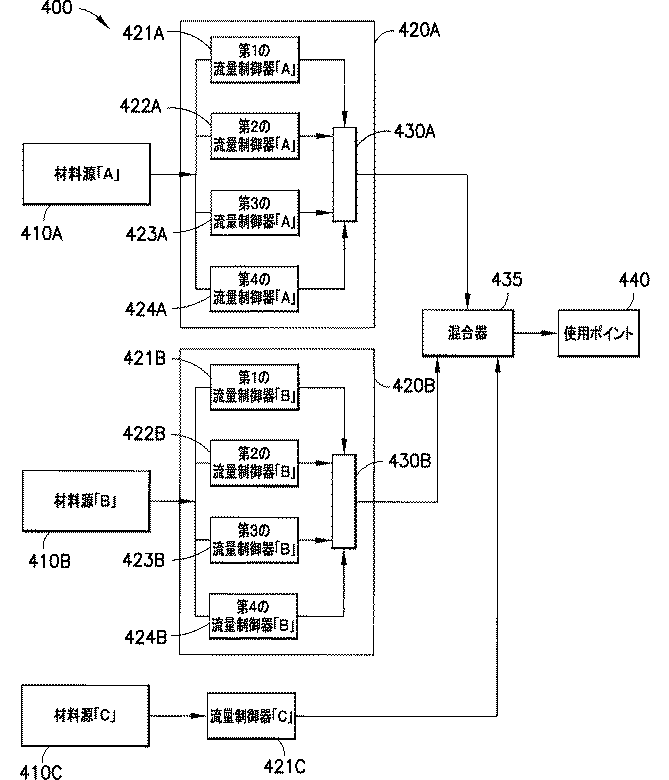
ここで、PSImは圧力測定値であり、PSIwはH2O2が0%の圧力であり、KはH2O2の濃度である。他の温度及び濃度の場合は、(密度対過酸化水素濃度に対応し、必要以上の実験をせずに当業者には容易に入手可能又は導出可能である)ルックアップテーブル又は数学的関数のフィッティング曲線を使用して、固定高さの柱を使用するか、既知の固定した容積を有する槽に供給された溶液によって加えられた圧力を測定する上記方法と矛盾がない濃度を求めることができる。 Here, PSI m is a pressure measurement value, PSI w is the pressure at which H 2 O 2 is 0%, and K is the concentration of H 2 O 2 . For other temperatures and concentrations, a look-up table or mathematical function (corresponding to density vs. hydrogen peroxide concentration and readily available or derived by one of ordinary skill in the art without undue experimentation) The fitting curve can be used to determine a concentration that is consistent with the above method of measuring the pressure applied by a solution supplied to a tank with a fixed height or using a known fixed volume. .
[0079] 高さ5フィート(1.52m)の柱を利用するために、この方法の測定分解能を計算することができる。5フィート(1.52m)の純水の柱によって加えられる圧力は2.227psi(15.35kPa)である。5フィート(1.52m)の過酸化水素30%と水70%の溶液の柱によって加えられる圧力は2.45psi(16.89kPa)である。0〜10psiの圧力範囲でセンサの誤差範囲が±0.05%psiと仮定すると、それぞれ2.455psi(16.93kPa)及び2.445psi(16.86kPa)というプラスとマイナスの誤差境界を確立することができる。上記の式にこの境界値を利用すると、30.67%というプラスの境界過酸化水素濃度、及び29.33%というマイナスの境界過酸化水素濃度になる。したがって、上記方法を使用するための濃度分解能は、水中に30%の過酸化水素がある濃度で±0.67%である。 [0079] In order to utilize a 5 foot (1.52 m) high column, the measurement resolution of this method can be calculated. The pressure applied by a 5 foot (1.52 m) column of pure water is 2.227 psi (15.35 kPa). The pressure applied by a column of 5 feet (1.52 m) of 30% hydrogen peroxide and 70% water is 2.45 psi (16.89 kPa). Assuming a sensor error range of ± 0.05% psi in the 0-10 psi pressure range, establish positive and negative error boundaries of 2.455 psi (16.93 kPa) and 2.445 psi (16.86 kPa), respectively. be able to. Using this boundary value in the above equation results in a positive boundary hydrogen peroxide concentration of 30.67% and a negative boundary hydrogen peroxide concentration of 29.33%. Therefore, the concentration resolution for using the above method is ± 0.67% at a concentration of 30% hydrogen peroxide in water.
[0080]上記開示は、複数成分の溶液又は混合物の少なくとも1つの成分の濃度を求める方法が、以下のステップ(A)及び(B)を含むことができることを示す。すなわち、(A)所期の高さの柱内で溶液又は混合物によって加えられる頭部圧力を測定するか、固定容積槽内に配置された溶液又は混合物の総質量を測定するステップ、及び(B)測定ステップの結果から、溶液又は混合物の少なくとも1つの成分の濃度を計算するステップ、である。 [0080] The above disclosure shows that a method for determining the concentration of at least one component of a multi-component solution or mixture can include the following steps (A) and (B). (A) measuring the head pressure applied by the solution or mixture in the column of the desired height, or measuring the total mass of the solution or mixture placed in the fixed volume tank; and (B ) Calculating the concentration of at least one component of the solution or mixture from the result of the measuring step.
[0081] 本明細書では、本発明の特定の態様、形態及び例示的実施形態を参照しながら本発明を説明してきたが、本明細書の開示に基づいて本発明の当業者であれば思い付くように、本発明のユーティリティはこのように限定されず、多数の他の変形、修正及び代替実施形態に拡大され、それを含むことが理解される。同様に、特許請求の範囲に記載される本発明は、このような変形、修正及び代替実施形態をその精神及び範囲内に含むものとして広義に想定され、解釈されるべきである。 [0081] While the invention has been described herein with reference to specific aspects, embodiments and exemplary embodiments of the invention, one of ordinary skill in the art of the invention will be able to conceive based on the disclosure herein. Thus, it is understood that the utility of the present invention is not so limited, but extends to and includes numerous other variations, modifications, and alternative embodiments. Similarly, the invention as claimed should be construed broadly and interpreted as including such variations, modifications, and alternative embodiments within the spirit and scope thereof.
Claims (41)
前記ライナを拡張させて、供給材料源から供給材料を前記ライナの内容積に引き込むために、前記間隙空間に準大気圧を適用するステップを含む、方法。 Using the collapsible liner disposed in an overpack container that defines a gap space between the liner and the container, the method comprising:
Applying a sub-atmospheric pressure to the interstitial space to expand the liner and draw feed material from a feed source into the inner volume of the liner.
前記第1の流量制御器の複数の流量制御器が同時に動作している場合に、前記複数の第1の供給材料流量制御器からの前記第1の供給材料の流れを選択的に組み合わせるように動作状態で配置構成された少なくとも1つの流れ統合要素と、を備える、
供給材料搬送システム。 A plurality of first feed flow controllers arranged in parallel and in fluid communication with a first feed source;
Selectively combining the flow of the first feed from the plurality of first feed flow controllers when the plurality of flow controllers of the first flow controller are operating simultaneously. At least one flow integration element arranged in an operating state,
Feed material transport system.
前記少なくとも1つの流れ統合要素が、前記第2の供給材料流量制御器からの前記第2の供給材料の流れを前記第1の供給材料の流れと組み合わせるように動作状態で配置構成される、請求項8から10のいずれか1項に記載の供給材料搬送システム。 A second feed flow controller in fluid communication with the second feed source;
The at least one flow integration element is configured to be operatively configured to combine the second feed flow from the second feed flow controller with the first feed flow. Item 11. The feed material conveyance system according to any one of Items 8 to 10.
前記少なくとも1つの流れ統合要素が、前記第3の供給材料流量制御器からの前記第3の供給材料の流れを、前記第1の供給材料及び前記第2の供給材料のうち少なくとも1つの流れと組み合わせるように動作状態で配置構成される、請求項11に記載の供給材料搬送システム。 A third feed flow controller in fluid communication with the third feed source;
The at least one flow integrating element directs the third feed flow from the third feed flow controller to at least one flow of the first feed and the second feed. The feed material delivery system of claim 11, wherein the feed material delivery system is configured in an operational state to combine.
前記少なくとも1つの流れ統合要素が、前記第2の供給材料流量制御器からの前記第2の供給材料の流れを前記第1の供給材料の流れと組み合わせるように動作状態で配置構成される、請求項8から10のいずれか1項に記載の供給材料搬送システム。 A plurality of second feed flow controllers arranged in parallel and in fluid communication with the second feed source;
The at least one flow integration element is configured to be operatively configured to combine the second feed flow from the second feed flow controller with the first feed flow. Item 11. The feed material conveyance system according to any one of Items 8 to 10.
各第1の供給材料流量制御器が、その対応する出力信号に応答して第1の供給材料の流量を制御するように構成される、請求項8から10のいずれか1項に記載の供給材料搬送システム。 Each first feed flow controller of the plurality of first feed flow controllers comprises an integral mass or flow sensing element arranged to generate a corresponding output signal;
11. A feed according to any one of claims 8 to 10, wherein each first feed flow controller is configured to control the flow of the first feed in response to its corresponding output signal. Material transport system.
総流量の偏差又は誤差を減少させるために、前記複数の第1の流量制御器のうち少なくとも幾つかの流量制御器を選択的に動作させるステップと、
前記第1の流量制御器のうち複数の流量制御器が同時に動作している場合に、前記複数の第1の供給材料流量制御器からの前記第1の供給材料の流れを組み合わせるステップと、を含む、方法。 Flowing a first feed from a first feed source through a plurality of parallel first feed flow controllers;
Selectively operating at least some of the plurality of first flow controllers to reduce a total flow deviation or error;
Combining a flow of the first feed from the plurality of first feed flow controllers when a plurality of flow controllers of the first flow controllers are operating simultaneously. Including.
前記第2の供給材料流量制御器からの前記第2の供給材料の流れを前記第1の供給材料の流れと組み合わせるステップと、
をさらに含む、請求項21から23のいずれか1項に記載の方法。 Flowing a second feed material from a second feed source through a second feed flow controller;
Combining the second feed stream from the second feed flow controller with the first feed stream;
24. The method of any one of claims 21 to 23, further comprising:
前記第3の供給材料流量制御器からの前記第3の供給材料の流れを、前記第1の供給材料及び/又は前記第2の供給材料の流れと組み合わせるステップと、
をさらに含む、請求項24に記載の方法。 Flowing a third feed from a third feed source through a third feed flow controller;
Combining the third feed flow from the third feed flow controller with the first feed and / or the second feed flow;
25. The method of claim 24, further comprising:
前記複数の第2の供給材料流量制御器からの前記第2の供給材料のうち少なくとも1つの流れを前記第1の供給材料の流れと組み合わせるステップと、
をさらに含む、請求項21から23のいずれか1項に記載の方法。 Flowing a second feed from a second feed source through a plurality of parallel second feed flow controllers, wherein at least two flow controllers of the plurality of second flow controllers Having different ranges of calibrated flow rates;
Combining at least one flow of the second feeds from the plurality of second feed flow controllers with the flow of the first feed;
24. The method of any one of claims 21 to 23, further comprising:
第1の供給材料の前記総流量が前記複数の第1の流量制御器を通過可能である、請求項21から23のいずれか1項に記載の方法。 Passing at least about 80% of the total flow rate of the first feed through one of the plurality of first flow controllers;
24. A method according to any one of claims 21 to 23, wherein the total flow rate of a first feed is capable of passing through the plurality of first flow controllers.
各第1の供給材料流量制御器が、その対応する出力信号に応答して第1の供給材料の流量を制御するように構成される、請求項21から23のいずれか1項に記載の方法。 Each first feed flow controller of the plurality of first feed flow controllers comprises an integral mass or flow sensing element arranged to generate a corresponding output signal;
24. A method according to any one of claims 21 to 23, wherein each first feed flow controller is configured to control the flow rate of the first feed in response to its corresponding output signal. .
前記複数の圧力分配容器の各圧力分配容器の前記間隙空間の加圧を制御するように配置構成された少なくとも1つの加圧制御要素と、
前記複数の供給材料圧力分配容器によって分配される供給材料を組み合わせるように配置構成された少なくとも1つの統合要素と、を備え、
各供給材料圧力分配容器が、前記ライナの内容積と流体連通する供給材料ポートを有し、少なくとも1つのポートが、前記間隙空間と流体連通し、前記間隙空間を減圧するように構成された減圧装置と流体連通する、
システム。 A plurality of feed pressure distribution containers that contain a plurality of feed materials, each pressure distribution container having a foldable liner disposed within the overpack container and defining a gap space between itself and the overpack container A plurality of feed pressure distribution containers, each pressure distribution container enclosing a different feed material in its foldable liner;
At least one pressurization control element arranged to control pressurization of the gap space of each pressure distribution container of the plurality of pressure distribution containers;
At least one integrated element arranged to combine the feeds distributed by the plurality of feed pressure distribution containers;
Each feed pressure distribution container has a feed port in fluid communication with the inner volume of the liner, and at least one port is in fluid communication with the gap space and configured to depressurize the gap space In fluid communication with the device,
system.
(ii)前記複数の圧力分配容器の各圧力分配容器の前記間隙空間の加圧を制御するように配置構成された少なくとも1つの加圧制御要素と、
(iii)前記複数の供給材料圧力分配容器によって分配される供給材料を組み合わせるように配置構成された少なくとも1つの統合要素と、
を利用する供給材料調合方法であって、
前記複数の圧力分配容器から供給材料を分配するステップと、
前記複数の供給材料のうち少なくとも2つの供給材料で複数の異なる組合せを生成するステップと、
意図された用途にとって有効又は最適である1つ又は複数の供給材料の組合せを決定するために、前記複数の異なる組合せを検査するステップと、
を含む、方法。 (I) a plurality of feed material pressure distribution containers that contain a plurality of feed materials, wherein each pressure distribution container is disposed within an overpack container and includes a collapsible liner that defines a gap space between itself and the overpack container; A plurality of feed pressure distribution containers, each pressure distribution container enclosing a different feed material in its foldable liner;
(Ii) at least one pressurization control element arranged to control pressurization of the gap space of each pressure distribution container of the plurality of pressure distribution containers;
(Iii) at least one integrated element arranged to combine the feeds distributed by the plurality of feed pressure distribution containers;
A feed material blending method using
Dispensing a feed from the plurality of pressure dispensing containers;
Generating a plurality of different combinations with at least two of the plurality of feeds;
Inspecting the plurality of different combinations to determine a combination of one or more feed materials that is effective or optimal for the intended application;
Including a method.
(A)所与の高さの柱内にある前記溶液又は混合物によって加えられる頭部圧力を測定するか、固定容積の槽内に配置された前記溶液又は混合物の総質量を測定するステップと、
(B)前記測定ステップの結果から前記溶液又は混合物の少なくとも1つの成分の濃度を計算するステップと、
を含む、方法。 A method for determining the concentration of at least one component of a multi-component solution or mixture, wherein the density of each individual component of said solution or mixture is known;
(A) measuring the head pressure applied by the solution or mixture in a column of a given height, or measuring the total mass of the solution or mixture placed in a fixed volume tank;
(B) calculating the concentration of at least one component of the solution or mixture from the result of the measuring step;
Including a method.
Applications Claiming Priority (2)
| Application Number | Priority Date | Filing Date | Title |
|---|---|---|---|
| US18581709P | 2009-06-10 | 2009-06-10 | |
| US61/185,817 | 2009-06-10 |
Related Parent Applications (1)
| Application Number | Title | Priority Date | Filing Date |
|---|---|---|---|
| JP2012515060A Division JP5863646B2 (en) | 2009-06-10 | 2010-06-08 | Fluid processing system and method |
Related Child Applications (1)
| Application Number | Title | Priority Date | Filing Date |
|---|---|---|---|
| JP2016021497A Division JP6151810B2 (en) | 2009-06-10 | 2016-02-08 | Fluid processing system and method |
Publications (2)
| Publication Number | Publication Date |
|---|---|
| JP2015178391A true JP2015178391A (en) | 2015-10-08 |
| JP5883977B2 JP5883977B2 (en) | 2016-03-15 |
Family
ID=43309435
Family Applications (3)
| Application Number | Title | Priority Date | Filing Date |
|---|---|---|---|
| JP2012515060A Active JP5863646B2 (en) | 2009-06-10 | 2010-06-08 | Fluid processing system and method |
| JP2015124836A Active JP5883977B2 (en) | 2009-06-10 | 2015-06-22 | Fluid processing system and method |
| JP2016021497A Active JP6151810B2 (en) | 2009-06-10 | 2016-02-08 | Fluid processing system and method |
Family Applications Before (1)
| Application Number | Title | Priority Date | Filing Date |
|---|---|---|---|
| JP2012515060A Active JP5863646B2 (en) | 2009-06-10 | 2010-06-08 | Fluid processing system and method |
Family Applications After (1)
| Application Number | Title | Priority Date | Filing Date |
|---|---|---|---|
| JP2016021497A Active JP6151810B2 (en) | 2009-06-10 | 2016-02-08 | Fluid processing system and method |
Country Status (8)
| Country | Link |
|---|---|
| US (2) | US9038855B2 (en) |
| EP (2) | EP3133636B1 (en) |
| JP (3) | JP5863646B2 (en) |
| KR (2) | KR101936536B1 (en) |
| CN (1) | CN102460640A (en) |
| SG (1) | SG176676A1 (en) |
| TW (1) | TWI564501B (en) |
| WO (1) | WO2010144439A2 (en) |
Cited By (1)
| Publication number | Priority date | Publication date | Assignee | Title |
|---|---|---|---|---|
| CN111483969A (en) * | 2020-04-22 | 2020-08-04 | 中国科学院空间应用工程与技术中心 | Liquid working medium filling device and method applied to loop system |
Families Citing this family (28)
| Publication number | Priority date | Publication date | Assignee | Title |
|---|---|---|---|---|
| EP3133636B1 (en) * | 2009-06-10 | 2019-01-02 | Entegris, Inc. | Fluid processing systems and method |
| PL2715737T3 (en) * | 2011-06-02 | 2016-10-31 | Method for storing hazardous waste material | |
| AT513651B1 (en) * | 2012-11-21 | 2015-06-15 | Waizenauer Dietmar Bsc | Mixing plant for viscous media |
| JP6340417B2 (en) * | 2013-06-04 | 2018-06-06 | テトラ ラバル ホールディングス アンド ファイナンス エス エイ | Devices and methods in filling machines |
| JP5826874B2 (en) * | 2014-02-20 | 2015-12-02 | 株式会社セブン・セブン | Coffee storage container |
| CN103801203B (en) * | 2014-03-06 | 2015-08-19 | 汪保和 | Based on the rigid container gas mixing device and method of built-in flexible containers |
| US9750663B2 (en) * | 2014-03-31 | 2017-09-05 | Aesynt | Systems, methods, apparatuses, and computer program products for providing interim volume verification of a fluid |
| DE102014207300B4 (en) * | 2014-04-16 | 2021-07-29 | Bayerische Motoren Werke Aktiengesellschaft | Method for producing a tank, in particular a motor vehicle tank |
| TWI549745B (en) * | 2014-05-16 | 2016-09-21 | 財團法人工業技術研究院 | Apparatus and method for mixing solution and monitoring particles in solution |
| US10709206B2 (en) * | 2015-11-30 | 2020-07-14 | Nike, Inc. | Method of filling electrorheological fluid structure |
| US11221406B2 (en) | 2017-05-09 | 2022-01-11 | Honeywell International Inc. | Guided wave radar for consumable particle monitoring |
| AR113037A1 (en) * | 2017-08-22 | 2020-01-22 | Scherer Technologies Llc R P | SYSTEMS AND METHODS FOR FILLING CONTAINERS |
| JP6931742B2 (en) | 2017-08-31 | 2021-09-08 | ナイキ イノベイト シーブイ | Degassing of electrorheological fluid |
| EP3712087A4 (en) | 2017-11-17 | 2021-07-21 | Innerbottle Co., Ltd. | Container device capable of storing liquid and manufacturing method therefor |
| KR101984766B1 (en) * | 2017-12-21 | 2019-09-24 | (주)이너보틀 | Coupling Apparatus for Elastic Pouch Container |
| JP6964295B2 (en) * | 2018-05-16 | 2021-11-10 | 株式会社コーセン社 | Fluid filling device |
| JP6578460B1 (en) * | 2019-03-29 | 2019-09-18 | ヤマト科学株式会社 | Container piping connection structure |
| US11559774B2 (en) | 2019-12-30 | 2023-01-24 | Marathon Petroleum Company Lp | Methods and systems for operating a pump at an efficiency point |
| CA3104319C (en) | 2019-12-30 | 2023-01-24 | Marathon Petroleum Company Lp | Methods and systems for spillback control of in-line mixing of hydrocarbon liquids |
| US11607654B2 (en) * | 2019-12-30 | 2023-03-21 | Marathon Petroleum Company Lp | Methods and systems for in-line mixing of hydrocarbon liquids |
| CA3103416C (en) | 2019-12-30 | 2022-01-25 | Marathon Petroleum Company Lp | Methods and systems for inline mixing of hydrocarbon liquids |
| KR102129226B1 (en) * | 2020-04-03 | 2020-07-01 | 윤영기 | Semiconductor chemical supply system using simulator |
| US20220025517A1 (en) * | 2020-07-27 | 2022-01-27 | Enchip Enterprise Llc | Semiconductor Processing System, and Control Assembly and Method Thereof |
| US11655940B2 (en) | 2021-03-16 | 2023-05-23 | Marathon Petroleum Company Lp | Systems and methods for transporting fuel and carbon dioxide in a dual fluid vessel |
| US11578836B2 (en) | 2021-03-16 | 2023-02-14 | Marathon Petroleum Company Lp | Scalable greenhouse gas capture systems and methods |
| KR20220167698A (en) * | 2021-06-14 | 2022-12-21 | 삼성전자주식회사 | Apparatus for supplying fluid and apparatus for processing substrate including the same |
| US11447877B1 (en) | 2021-08-26 | 2022-09-20 | Marathon Petroleum Company Lp | Assemblies and methods for monitoring cathodic protection of structures |
| US11686070B1 (en) | 2022-05-04 | 2023-06-27 | Marathon Petroleum Company Lp | Systems, methods, and controllers to enhance heavy equipment warning |
Citations (4)
| Publication number | Priority date | Publication date | Assignee | Title |
|---|---|---|---|---|
| US4818706A (en) * | 1983-04-19 | 1989-04-04 | American Monitor Corporation | Reagent-dispensing system and method |
| JPH09122464A (en) * | 1995-11-06 | 1997-05-13 | Ee D:Kk | Device for mixing dissimilar fluids |
| JP2005538902A (en) * | 2002-05-03 | 2005-12-22 | アドバンスド テクノロジー マテリアルズ,インコーポレイテッド | Apparatus and method for minimizing the formation of particles in ultra high purity liquids |
| JP2006501075A (en) * | 2002-09-30 | 2006-01-12 | エマーソン エレクトリック カンパニー | Flow regulation system |
Family Cites Families (37)
| Publication number | Priority date | Publication date | Assignee | Title |
|---|---|---|---|---|
| GB8504930D0 (en) * | 1985-02-26 | 1985-03-27 | Corrugated Prod Ltd | Packages for carbonated beverages |
| US4723969A (en) * | 1986-09-22 | 1988-02-09 | Demarco Thomas M | Vacuum loader and process for removing asbestos and other hazardous material |
| US4854481A (en) * | 1988-05-09 | 1989-08-08 | The Gates Rubber Company | Collapsible fluid storage receptacle |
| GB8906409D0 (en) | 1989-03-21 | 1989-05-04 | Lambrechts Nv | Container for liquids |
| US5447183A (en) * | 1989-09-15 | 1995-09-05 | B.A.G. Corp. | Vacuum fill system |
| US5148945B1 (en) | 1990-09-17 | 1996-07-02 | Applied Chemical Solutions | Apparatus and method for the transfer and delivery of high purity chemicals |
| US5343901A (en) * | 1993-03-17 | 1994-09-06 | Philip Meshberg | Insertable barrier bag or liner for a narrow neck dispensing container and method of filling such a barrier bag or liner |
| EP0644993B1 (en) | 1992-06-08 | 1996-09-11 | Saes Getters S.P.A. | Evacuated thermally insulating jacket, in particular the jacket of a dewar or of another cryogenic device |
| US6062430A (en) * | 1993-05-05 | 2000-05-16 | Ing. Erich Pfeiffer Gmbh | Dispensing container with variable volume compensation |
| US5383574A (en) * | 1993-07-19 | 1995-01-24 | Microbar Sytems, Inc. | System and method for dispensing liquid from storage containers |
| US5526957A (en) * | 1994-06-23 | 1996-06-18 | Insta-Foam Products, Inc. | Multi-component dispenser with self-pressurization system |
| US5673818A (en) * | 1995-07-19 | 1997-10-07 | Chrysler Corporation | Paint tote with collapsible liner |
| JP3333121B2 (en) * | 1996-12-25 | 2002-10-07 | 東京エレクトロン株式会社 | Coating device |
| US5899362A (en) * | 1997-05-01 | 1999-05-04 | Moran; Michael J. | Method and apparatus for combining liquids |
| US6019250A (en) | 1997-10-14 | 2000-02-01 | The Boc Group, Inc. | Liquid dispensing apparatus and method |
| US6076541A (en) * | 1997-11-26 | 2000-06-20 | Pozniak; Peter M. | Dispensing system and method for dispensing an aqueous solution |
| US6101816A (en) | 1998-04-28 | 2000-08-15 | Advanced Technology Materials, Inc. | Fluid storage and dispensing system |
| WO1999056189A1 (en) | 1998-04-30 | 1999-11-04 | The Boc Group, Inc. | Conductivity feedback control system for slurry blending |
| US6168048B1 (en) * | 1998-09-22 | 2001-01-02 | American Air Liquide, Inc. | Methods and systems for distributing liquid chemicals |
| SE518114C2 (en) * | 1998-09-28 | 2002-08-27 | Asept Int Ab | Pumping device for pumping liquid food |
| US20030010792A1 (en) | 1998-12-30 | 2003-01-16 | Randy Forshey | Chemical mix and delivery systems and methods thereof |
| US6923568B2 (en) | 2000-07-31 | 2005-08-02 | Celerity, Inc. | Method and apparatus for blending process materials |
| GB0022710D0 (en) * | 2000-09-15 | 2000-11-01 | Bp Oil Int | Dispenser and method of use |
| JP4209688B2 (en) | 2001-05-24 | 2009-01-14 | セレリティ・インコーポレーテッド | Method and apparatus for supplying a determined ratio of process fluid |
| US6698619B2 (en) | 2002-05-03 | 2004-03-02 | Advanced Technology Materials, Inc. | Returnable and reusable, bag-in-drum fluid storage and dispensing container system |
| US6848599B2 (en) | 2002-08-22 | 2005-02-01 | Illinois Tool Works Inc. | Adhesive container and method of filling |
| US6708502B1 (en) | 2002-09-27 | 2004-03-23 | The Regents Of The University Of California | Lightweight cryogenic-compatible pressure vessels for vehicular fuel storage |
| US6884145B2 (en) * | 2002-11-22 | 2005-04-26 | Samsung Austin Semiconductor, L.P. | High selectivity slurry delivery system |
| CA2552310A1 (en) * | 2004-01-07 | 2005-07-28 | Walker-Dawson Interests, Inc. | Vacuum container system and related method |
| US7410106B2 (en) | 2005-02-08 | 2008-08-12 | 3M Innovative Properties Company | Pressurized liquid supply assembly |
| SG10201507693UA (en) | 2005-06-06 | 2015-10-29 | Advanced Tech Materials | Fluid storage and dispensing systems and processes |
| TWI552797B (en) | 2005-06-22 | 2016-10-11 | 恩特葛瑞斯股份有限公司 | Apparatus and process for integrated gas blending |
| CN103101867B (en) * | 2006-06-13 | 2017-07-28 | 恩特格里斯公司 | Fuid distribution system and method, connector, microelectronic product manufacturing equipment |
| US20100025430A1 (en) | 2007-01-30 | 2010-02-04 | Advanced Technology Materials, Inc. | Prevention of liner choke-off in liner-based pressure dispensation system |
| US20100128555A1 (en) * | 2007-05-09 | 2010-05-27 | Advanced Technology Materials, Inc. | Systems and methods for material blending and distribution |
| JP2011506110A (en) * | 2007-12-06 | 2011-03-03 | フォアサイト プロセッシング,エルエルシー | System and method for conveying a work material mixture containing fluid |
| EP3133636B1 (en) * | 2009-06-10 | 2019-01-02 | Entegris, Inc. | Fluid processing systems and method |
-
2010
- 2010-06-08 EP EP16183735.6A patent/EP3133636B1/en active Active
- 2010-06-08 CN CN2010800260475A patent/CN102460640A/en active Pending
- 2010-06-08 KR KR1020177032454A patent/KR101936536B1/en active IP Right Grant
- 2010-06-08 US US13/375,462 patent/US9038855B2/en active Active
- 2010-06-08 EP EP10786688.1A patent/EP2441084B1/en active Active
- 2010-06-08 KR KR1020127000474A patent/KR20120036953A/en active Application Filing
- 2010-06-08 JP JP2012515060A patent/JP5863646B2/en active Active
- 2010-06-08 SG SG2011089836A patent/SG176676A1/en unknown
- 2010-06-08 WO PCT/US2010/037759 patent/WO2010144439A2/en active Application Filing
- 2010-06-10 TW TW099118915A patent/TWI564501B/en active
-
2015
- 2015-05-04 US US14/703,467 patent/US9586188B2/en active Active
- 2015-06-22 JP JP2015124836A patent/JP5883977B2/en active Active
-
2016
- 2016-02-08 JP JP2016021497A patent/JP6151810B2/en active Active
Patent Citations (6)
| Publication number | Priority date | Publication date | Assignee | Title |
|---|---|---|---|---|
| US4818706A (en) * | 1983-04-19 | 1989-04-04 | American Monitor Corporation | Reagent-dispensing system and method |
| JPH09122464A (en) * | 1995-11-06 | 1997-05-13 | Ee D:Kk | Device for mixing dissimilar fluids |
| JP2005538902A (en) * | 2002-05-03 | 2005-12-22 | アドバンスド テクノロジー マテリアルズ,インコーポレイテッド | Apparatus and method for minimizing the formation of particles in ultra high purity liquids |
| US7188644B2 (en) * | 2002-05-03 | 2007-03-13 | Advanced Technology Materials, Inc. | Apparatus and method for minimizing the generation of particles in ultrapure liquids |
| JP2006501075A (en) * | 2002-09-30 | 2006-01-12 | エマーソン エレクトリック カンパニー | Flow regulation system |
| US7204679B2 (en) * | 2002-09-30 | 2007-04-17 | Emerson Electric Co. | Flow control system |
Cited By (2)
| Publication number | Priority date | Publication date | Assignee | Title |
|---|---|---|---|---|
| CN111483969A (en) * | 2020-04-22 | 2020-08-04 | 中国科学院空间应用工程与技术中心 | Liquid working medium filling device and method applied to loop system |
| CN111483969B (en) * | 2020-04-22 | 2022-01-28 | 中国科学院空间应用工程与技术中心 | Liquid working medium filling device and method applied to loop system |
Also Published As
| Publication number | Publication date |
|---|---|
| US20150321897A1 (en) | 2015-11-12 |
| TW201104127A (en) | 2011-02-01 |
| EP3133636A2 (en) | 2017-02-22 |
| US20120138631A1 (en) | 2012-06-07 |
| EP2441084B1 (en) | 2016-09-21 |
| US9586188B2 (en) | 2017-03-07 |
| SG176676A1 (en) | 2012-01-30 |
| EP2441084A2 (en) | 2012-04-18 |
| JP5883977B2 (en) | 2016-03-15 |
| JP2016094255A (en) | 2016-05-26 |
| WO2010144439A2 (en) | 2010-12-16 |
| EP3133636B1 (en) | 2019-01-02 |
| KR20170127064A (en) | 2017-11-20 |
| KR101936536B1 (en) | 2019-01-08 |
| JP6151810B2 (en) | 2017-06-21 |
| CN102460640A (en) | 2012-05-16 |
| JP5863646B2 (en) | 2016-02-16 |
| EP2441084A4 (en) | 2014-05-28 |
| TWI564501B (en) | 2017-01-01 |
| WO2010144439A3 (en) | 2011-03-03 |
| EP3133636A3 (en) | 2017-05-03 |
| KR20120036953A (en) | 2012-04-18 |
| US9038855B2 (en) | 2015-05-26 |
| JP2012529407A (en) | 2012-11-22 |
Similar Documents
| Publication | Publication Date | Title |
|---|---|---|
| JP6151810B2 (en) | Fluid processing system and method | |
| JP5698456B2 (en) | Liquid distribution system including gas removal | |
| US10676341B2 (en) | Liquid dispensing systems with gas removal and sensing capabilities | |
| US20100128555A1 (en) | Systems and methods for material blending and distribution | |
| JP6397766B2 (en) | System and method for delivering fluid | |
| KR20080009137A (en) | Liner-based liquid storage and dispensing systems with empty detection capability | |
| TW200307646A (en) | Apparatus and method for minimizing the generation of particles in ultrapure liquids | |
| KR20050013991A (en) | Chemical mix and delivery systems and methods thereof | |
| JP2011157136A (en) | Liquid dispensing method and system with headspace gas removal | |
| JPS6084136A (en) | Supply method and supply monitoring apparatus of chemical liquid from hermetically closed goods-delivery can | |
| WO2015066448A1 (en) | Apparatus and method for direct contact pressure dispensing using floating liquid extraction element |
Legal Events
| Date | Code | Title | Description |
|---|---|---|---|
| A521 | Request for written amendment filed |
Free format text: JAPANESE INTERMEDIATE CODE: A523 Effective date: 20150717 |
|
| A621 | Written request for application examination |
Free format text: JAPANESE INTERMEDIATE CODE: A621 Effective date: 20150717 |
|
| A871 | Explanation of circumstances concerning accelerated examination |
Free format text: JAPANESE INTERMEDIATE CODE: A871 Effective date: 20150717 |
|
| A975 | Report on accelerated examination |
Free format text: JAPANESE INTERMEDIATE CODE: A971005 Effective date: 20150813 |
|
| A131 | Notification of reasons for refusal |
Free format text: JAPANESE INTERMEDIATE CODE: A131 Effective date: 20150820 |
|
| A521 | Request for written amendment filed |
Free format text: JAPANESE INTERMEDIATE CODE: A523 Effective date: 20151029 |
|
| TRDD | Decision of grant or rejection written | ||
| A01 | Written decision to grant a patent or to grant a registration (utility model) |
Free format text: JAPANESE INTERMEDIATE CODE: A01 Effective date: 20160112 |
|
| A61 | First payment of annual fees (during grant procedure) |
Free format text: JAPANESE INTERMEDIATE CODE: A61 Effective date: 20160208 |
|
| R150 | Certificate of patent or registration of utility model |
Ref document number: 5883977 Country of ref document: JP Free format text: JAPANESE INTERMEDIATE CODE: R150 |
|
| R250 | Receipt of annual fees |
Free format text: JAPANESE INTERMEDIATE CODE: R250 |
|
| R250 | Receipt of annual fees |
Free format text: JAPANESE INTERMEDIATE CODE: R250 |
|
| R250 | Receipt of annual fees |
Free format text: JAPANESE INTERMEDIATE CODE: R250 |
|
| R250 | Receipt of annual fees |
Free format text: JAPANESE INTERMEDIATE CODE: R250 |
|
| R250 | Receipt of annual fees |
Free format text: JAPANESE INTERMEDIATE CODE: R250 |
|
| R250 | Receipt of annual fees |
Free format text: JAPANESE INTERMEDIATE CODE: R250 |