JP2015178384A - double container - Google Patents
double container Download PDFInfo
- Publication number
- JP2015178384A JP2015178384A JP2014156924A JP2014156924A JP2015178384A JP 2015178384 A JP2015178384 A JP 2015178384A JP 2014156924 A JP2014156924 A JP 2014156924A JP 2014156924 A JP2014156924 A JP 2014156924A JP 2015178384 A JP2015178384 A JP 2015178384A
- Authority
- JP
- Japan
- Prior art keywords
- wall
- layer body
- foam
- air
- liquid
- Prior art date
- Legal status (The legal status is an assumption and is not a legal conclusion. Google has not performed a legal analysis and makes no representation as to the accuracy of the status listed.)
- Granted
Links
- 239000007788 liquid Substances 0.000 claims abstract description 148
- 238000000605 extraction Methods 0.000 claims abstract description 9
- 238000005187 foaming Methods 0.000 claims abstract description 3
- 239000006260 foam Substances 0.000 claims description 92
- 230000002093 peripheral effect Effects 0.000 claims description 34
- 238000005192 partition Methods 0.000 claims description 31
- 238000003825 pressing Methods 0.000 claims description 3
- 239000000463 material Substances 0.000 abstract description 3
- 239000003570 air Substances 0.000 abstract 6
- 239000012530 fluid Substances 0.000 abstract 3
- 239000012080 ambient air Substances 0.000 abstract 1
- 230000004308 accommodation Effects 0.000 description 9
- 239000000853 adhesive Substances 0.000 description 4
- 230000001070 adhesive effect Effects 0.000 description 4
- 229920003002 synthetic resin Polymers 0.000 description 4
- 239000000057 synthetic resin Substances 0.000 description 4
- 238000000071 blow moulding Methods 0.000 description 2
- 230000000717 retained effect Effects 0.000 description 2
- 230000005540 biological transmission Effects 0.000 description 1
- 239000002537 cosmetic Substances 0.000 description 1
- 230000007423 decrease Effects 0.000 description 1
- 230000032798 delamination Effects 0.000 description 1
- 238000011038 discontinuous diafiltration by volume reduction Methods 0.000 description 1
- 235000011194 food seasoning agent Nutrition 0.000 description 1
- 238000010030 laminating Methods 0.000 description 1
- 239000006210 lotion Substances 0.000 description 1
- 230000007257 malfunction Effects 0.000 description 1
- 238000000034 method Methods 0.000 description 1
- 238000012986 modification Methods 0.000 description 1
- 230000004048 modification Effects 0.000 description 1
- 230000000149 penetrating effect Effects 0.000 description 1
- 230000002441 reversible effect Effects 0.000 description 1
- 239000002453 shampoo Substances 0.000 description 1
- 239000000344 soap Substances 0.000 description 1
- 239000000126 substance Substances 0.000 description 1
- 230000026683 transduction Effects 0.000 description 1
- 238000010361 transduction Methods 0.000 description 1
- 238000009423 ventilation Methods 0.000 description 1
Images


Landscapes
- Containers And Packaging Bodies Having A Special Means To Remove Contents (AREA)
- Closures For Containers (AREA)
Abstract
Description
本発明は、内容液を収容する減容変形自在な内層体と、内層体を内側に収めて容器の外殻を形成する外層体とを備え、内容液の注出に伴って内層体のみが減容する二重容器に関するものであり、特に、内容液を泡状にして注出することができる技術に関する。 The present invention includes a volume-deformable inner layer body that contains the content liquid, and an outer layer body that houses the inner layer body to form the outer shell of the container, and only the inner layer body is extracted along with the dispensing of the content liquid. The present invention relates to a double container for volume reduction, and in particular, to a technique capable of pouring the content liquid into a foam.
化粧水などの化粧料や、シャンプーやリンス或いは液体石鹸、また食品調味料や薬品などを収納する容器としては、内容液を収容する減容変形自在な内層体と、内層体を内側に収めて容器の外殻を形成する外層体とを備え、外層体に、内外に通じる通気口を設け、内容液の注出に伴って内層体のみを減容させるようにした二重容器(デラミ容器、積層剥離容器とも言う)が知られている(例えば特許文献1)。この種の容器は、内層体内の内容液と外気との置換を行うことなく内容液を注出することができるので、特に、外気との接触によって品質が低下するおそれのある内容液を収納する容器として好適である。 As a container to store cosmetics such as lotion, shampoo, rinse or liquid soap, food seasoning or chemicals, etc. An outer layer body that forms an outer shell of the container, and the outer layer body is provided with a vent hole that communicates with the inside and outside, and only the inner layer body is reduced in volume as the content liquid is poured (delamid container, (Also referred to as a delamination container) is known (for example, Patent Document 1). Since this type of container can dispense the content liquid without replacing the content liquid in the inner layer with the outside air, it particularly stores the content liquid that may be deteriorated in quality due to contact with the outside air. Suitable as a container.
ところで、このような二重容器に収容される内容液は、従来、液状のままで注出させることが大半であり、他の形態(泡状)にして注出できるものは未だ種類が少ないのが現状である。このため、内容液によっては所望する泡質を得ることができず、未だ開発の余地が残されている。 By the way, the content liquid accommodated in such a double container is conventionally mostly poured out in a liquid state, and there are still few types that can be poured out in other forms (foam). Is the current situation. For this reason, the desired foam quality cannot be obtained depending on the content liquid, and there is still room for development.
ところで従来、内容液を泡状にして注出する容器では、内容液と空気とを予め混合させておく空間(気液混合室)を設け、空気と混合した内容液を、気液混合室の下流側に設けた発泡体を通過させることで発泡させるようにしている。しかし、気液混合室と発泡体を両方設けることは、容器のサイズを小型化する上で不利になる。 By the way, conventionally, in a container for pouring out the content liquid in the form of foam, a space (gas-liquid mixing chamber) in which the content liquid and air are mixed in advance is provided, and the content liquid mixed with air is supplied to the gas-liquid mixing chamber. It is made to foam by letting the foam provided in the downstream pass. However, providing both the gas-liquid mixing chamber and the foam is disadvantageous in reducing the size of the container.
本発明は、このような問題点を解決することを課題とするものであり、その目的は、収容した内容液と外気との接触が防止できるとともに、内容液と空気とを予め混合させる空間を設けることなく内容液を泡状にして注出することができる、新たな二重容器を提案するところにある。 An object of the present invention is to solve such problems. The purpose of the present invention is to prevent a contact between the contained content liquid and the outside air, and a space in which the content liquid and the air are mixed in advance. It is in the place of proposing a new double container that can be poured out in the form of foam without providing it.
本発明は、内容液を収容する減容変形自在な内層体と、該内層体を内側に収めるとともに口部周壁を貫通する通気口を有する外層体と、該通気口を内側に収める有蓋筒状の外壁を有し該外壁を該口部周壁に保持させてなる注出キャップとを備え、
前記注出キャップは、前記内層体に通じる貫通開口を有するとともに該内層体の上部開口を覆う隔壁と、前記外壁の内側にそれぞれ設けられる、該貫通開口に通じる液室及び前記通気口に通じる空気室とを有し、
前記外壁は、前記液室に通じる液流出口及び前記空気室に通じる空気流出口を有するとともに、該液流出口及び該空気流出口を取り囲む注出筒を有し、
前記注出筒の内側に、前記液流出口及び前記空気流出口の両方に接触する発泡体を設け、前記外層体への押圧によって、前記内層体の内容液及び該外層体と該内層体との相互間の空気を前記液流出口及び前記空気流出口から該発泡体へ個別に導入し、該発泡体で混合、発泡させて該注出筒から注出させる二重容器である。
The present invention relates to a volume-deformable inner layer body that contains a content liquid, an outer layer body that contains the inner layer body inside and has a vent hole that penetrates the peripheral wall of the mouth, and a covered cylindrical shape that contains the vent hole inside. A pouring cap that has an outer wall of the outer wall and holds the outer wall on the peripheral wall of the mouth,
The dispensing cap has a through opening that communicates with the inner layer body and covers a partition wall that covers the upper opening of the inner layer body, and a liquid chamber that is provided inside the outer wall and communicates with the through opening and air that communicates with the vent hole A chamber,
The outer wall has a liquid outlet that communicates with the liquid chamber and an air outlet that communicates with the air chamber, and a pouring cylinder that surrounds the liquid outlet and the air outlet,
A foam that is in contact with both the liquid outlet and the air outlet is provided inside the dispensing cylinder, and the inner layer body contents liquid, the outer layer body, and the inner layer body are pressed by the outer layer body. Are introduced into the foam separately from the liquid outlet and the air outlet, mixed and foamed with the foam, and discharged from the outlet cylinder.
前記液流出口及び前記空気流出口の何れか一方を、前記発泡体の中央部に接触させ、何れか他方を、何れか一方に指向させつつ該発泡体の縁部に接触させることが好ましい。 It is preferable that either one of the liquid outlet and the air outlet is brought into contact with the central portion of the foam, and one of the liquid outlet and the air outlet is brought into contact with an edge of the foam while being directed toward either one.
前記液流出口及び前記空気流出口の両方を、前記発泡体の中央部に個別に接触させるとともに、それぞれを相手側に向けて指向させることが好ましい。 It is preferable that both the liquid outlet and the air outlet are individually brought into contact with the central portion of the foam and directed toward the other side.
前記外壁は、前記発泡体の中央部において該発泡体に向けて膨出する膨出部を有し、該膨出部の周壁に、前記液流出口及び前記空気流出口の何れか一方を設けて該発泡体に接触させ、何れか他方を、該発泡体の縁部に接触させることが好ましい。 The outer wall has a bulging portion that bulges toward the foam at a central portion of the foam, and either one of the liquid outlet or the air outlet is provided on a peripheral wall of the bulged portion. It is preferable to bring the foam into contact with one of the other and the edge of the foam.
また本発明は、内容液を収容する減容変形自在な内層体と、該内層体を内側に収めるとともに口部周壁を貫通する通気口を有する外層体と、該通気口を内側に収める有蓋筒状の外壁を有し該外壁を該口部周壁に保持させてなる注出キャップとを備え、
前記注出キャップは、前記内層体に通じる貫通開口を有するとともに該内層体の上部開口を覆う隔壁と、前記外壁の内側にそれぞれ設けられる、該貫通開口に通じる液室及び前記通気口に通じる空気室とを有し、
前記液室は、前記貫通開口を取り囲む筒壁の内側において前記隔壁に対して間隔をあけて配される発泡体の底壁と該隔壁との間に設けられ、前記空気室は、該筒壁の外側において前記外壁と該隔壁との間に設けられ、
前記筒壁は、前記空気室に通じるとともに前記発泡体の周壁に向けて開口する空気流出口を有し、前記外層体への押圧によって、前記内層体の内容液及び該外層体と該内層体との相互間の空気を前記液室及び前記空気流出口から前記発泡体へ個別に導入し、該発泡体で混合、発泡させて、該発泡体の天壁側に設けた前記注出キャップの注出筒から注出させる二重容器である。
The present invention also provides a volume-reducible and deformable inner layer body that contains the content liquid, an outer layer body that contains the inner layer body inside and has a vent hole that penetrates the peripheral wall of the mouth, and a covered cylinder that contains the vent hole inside. A pour-out cap having an outer wall having a shape and holding the outer wall on the peripheral wall of the mouth,
The dispensing cap has a through opening that communicates with the inner layer body and covers a partition wall that covers the upper opening of the inner layer body, and a liquid chamber that is provided inside the outer wall and communicates with the through opening and air that communicates with the vent hole A chamber,
The liquid chamber is provided between the bottom wall of the foam and the partition wall, which is spaced from the partition wall inside the cylindrical wall surrounding the through-opening, and the air chamber is the cylindrical wall Between the outer wall and the partition wall on the outside of
The cylindrical wall has an air outlet that communicates with the air chamber and opens toward the peripheral wall of the foam, and by pressing against the outer layer body, the content liquid of the inner layer body and the outer layer body and the inner layer body Of the extraction cap provided on the top wall side of the foam by individually introducing the air between the liquid chamber and the air outlet into the foam, mixing and foaming with the foam It is a double container that is poured out from a dispensing tube.
本発明では、注出キャップの外壁に、液室に通じる液流出口、及び空気室に通じる空気流出口を設けるとともに、液流出口及び空気流出口を取り囲む注出筒を設け、注出筒の内側に、液流出口及び空気流出口の両方に接触する発泡体を設けている。すなわち、内容液を泡状にして注出するにあたり、従来設けていた気液混合室が不要になるので、容器サイズの小型化を図ることができる。 In the present invention, a liquid outlet that leads to the liquid chamber and an air outlet that leads to the air chamber are provided on the outer wall of the outlet cap, and an outlet cylinder that surrounds the liquid outlet and the air outlet is provided. Inside, a foam that contacts both the liquid outlet and the air outlet is provided. That is, when the content liquid is poured out in the form of foam, the gas-liquid mixing chamber that has been provided conventionally is not required, so that the container size can be reduced.
液流出口及び空気流出口の何れか一方を、発泡体の中央部に接触させ、何れか他方を、何れか一方に指向させつつ発泡体の縁部に接触させる場合は、発泡体に導入した内容液及び空気が混合しやすくなる。また、液流出口及び空気流出口の両方を、発泡体の中央部に個別に接触させるとともに、それぞれを相手側に向けて指向させる場合にも、内容液と空気が混合しやすくなる。これにより、注出させる泡の肌理をより細かくすることができる Either one of the liquid outlet and the air outlet is brought into contact with the center of the foam, and when the other is in contact with the edge of the foam while being directed to either one, it is introduced into the foam. The liquid and air can be easily mixed. Further, when both the liquid outlet and the air outlet are individually brought into contact with the central portion of the foam and are directed toward the other side, the content liquid and the air are easily mixed. Thereby, the texture of the foam to be poured out can be made finer.
外壁に、発泡体の中央部においてこの発泡体に向けて膨出する膨出部を設け、膨出部の周壁に、液流出口及び空気流出口の何れか一方を設けて該発泡体に接触させ、何れか他方を、発泡体の縁部に接触させる場合は、膨出部から流出する内容液及び空気の何れか一方に対し、その背後から何れか他方を送り込むことができるので、内容液及び空気がより混合しやすくなり、泡の肌理を一層細かくすることができる。 The outer wall is provided with a bulging portion that bulges toward the foam at the center of the foam, and either the liquid outlet or the air outlet is provided on the peripheral wall of the bulging portion to contact the foam. When either one is brought into contact with the edge of the foam, either one of the content liquid flowing out from the bulging portion and the air can be fed from behind the content liquid. And air becomes easier to mix, and the texture of the foam can be made finer.
また液室を、貫通開口を取り囲む筒壁の内側において隔壁に対して間隔をあけて配される発泡体の底壁と隔壁との間に設け、空気室を、筒壁の外側において外壁と隔壁との間に設け、筒壁に、空気室に通じるとともに発泡体の周壁に向けて開口する空気流出口を設けることにより、内容液及び空気が液室及び空気流出口から発泡体へ個別に導入されるので、このような構成でも気液混合室を不要にすることが可能である。 A liquid chamber is provided between the bottom wall and the partition wall of the foam, which is spaced from the partition wall on the inner side of the cylindrical wall surrounding the through opening, and an air chamber is provided on the outer side of the cylindrical wall. The liquid and air are individually introduced into the foam from the liquid chamber and the air outlet by providing an air outlet on the tube wall that leads to the air chamber and opens toward the peripheral wall of the foam. Therefore, even with such a configuration, the gas-liquid mixing chamber can be made unnecessary.
以下、図面を参照して、本発明をより具体的に説明する。なお、本明細書、特許請求の範囲、及び要約書において、「上」とは、二重容器を水平面上に載置した際に外層体の底部に対して注出キャップが位置する側であり、「下」とは、その反対側である。 Hereinafter, the present invention will be described more specifically with reference to the drawings. In this specification, claims, and abstract, “upper” means the side on which the pouring cap is located with respect to the bottom of the outer layer body when the double container is placed on a horizontal plane. “Lower” is the opposite side.
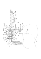
図1において、符号1Aは、本発明に従う二重容器の第一実施形態を示す。本実施形態の二重容器1Aは、内容液を収容する内層体2と、内層体2を内側に収める外層体3と、外層体3に装着される注出キャップ4Aを備えている。注出キャップ4Aは、中栓10Aと、移動弁体20と、ホルダー30Aと、空気用逆止弁40Aと、キャップ本体50Aと、外気導入用逆止弁60と、発泡体70Aと、オーバーキャップ80とで構成されている。
In FIG. 1,
内層体2は、その内側に内容液を収容する収容空間Sと、この収容空間Sにつながる上部開口2aを備えている。内層体2は薄肉の合成樹脂製であって、減容変形自在となっている。
The
外層体3は、円筒状の口部周壁3aに、図示を省略する復元自在な可撓性を有する胴部、及び胴部の下端を閉鎖する底部を連結したものである。口部周壁3aの外周面には雄ねじ部3bを設けている。また、口部周壁3aには、内層体2との相互間に空気を取り込むための貫通孔(通気口)3cを設けていて、更に、通気口3cを設けた外周面には、上下方向に雄ねじ部3bを切り欠く溝部3dを設けている。
The
本実施形態において内層体2と外層体3は、相互に相溶性が低い合成樹脂を剥離可能に積層させたものである。図示は省略するが内層体2と外層体3との間には、上下方向に延在して内層体2と外層体3とを部分的に接合する、1本或いは複数本の接着帯を設けてもよい。なお、このような内層体2と外層体3は、内層体2の合成樹脂素材と外層体3の合成樹脂素材とが積層されたパリソンを、ブロー成形することによって得ることができるが、他にも、試験管状に形成したプリフォームを2軸延伸ブロー成形することや、外層体及び内層体を個別に形成し、その後、内層体を外層体内に装着するようにしたものでもよい。
In this embodiment, the
中栓10Aは、内層体2の上部開口2aを覆う板状の隔壁11を備えている。隔壁11には、貫通開口12が設けられていて、更に、貫通開口12の縁部から下向きに延在する円筒状の筒状壁13が設けられている。筒状壁13の下端部は、下方に向けて縮径する縮径部13aとなっている。また隔壁11の下面には、口部周壁3aの内面との間で内層体2を挟む円筒状のシール壁14が設けられている。隔壁11の上面には、上方へ向けて延在する中栓環状壁15と、中栓環状壁15の一部を切り欠くとともに隔壁11の上面を凹ませた溝部16が設けられている。更に、隔壁11の縁部には、上方へ向けて延在する縁壁17が設けられていて、縁壁17の根元には、貫通孔18が設けられている。
The
筒状壁13内には、本実施形態では球状となる移動弁体20が設けられている。移動弁体20は、縮径部13aに着座することで、収容空間Sをシールすることができる。また、移動弁体20は、外層体3を起立姿勢から傾倒姿勢に姿勢変更することで縮径部13aから離反し、外層体3の胴部を押圧することによって筒状壁13との隙間を通して内容液を貫通開口12へ流すことができる。
In the
ホルダー30Aは、隔壁11上に配置される板状壁31を備えている。板状壁31には、溝部16に対応する部位に空気用貫通孔32が設けられ、また貫通開口12に対応する部位に液用貫通孔33が設けられている。板状壁31の下面には、液用貫通孔33を取り囲むとともに筒状壁13に挿通される円筒状の連結壁34が設けられている。また板状壁31の上面には、空気用貫通孔32を取り囲むとともに上方へ向けて延在する内側環状壁35と、中栓環状壁15によって取り囲まれる外側環状壁36が設けられている。
The holder 30 </ b> A includes a plate-
空気用逆止弁40Aは、筒状壁41の下端部に、アーム42を介して平板状の弁体43を一体に連結した形状となるものであり、所謂1点弁のように機能する。なお、1点弁に限定されるものではなく、3点弁等、従前の他の形態の逆止弁を用いることができる。空気用逆止弁40Aは、筒状壁41が内側環状壁35に挿入されるようにして取り付けられる。また通常時は、弁体43が、空気用貫通孔32を覆って板状壁31に着座する。
The
キャップ本体50Aは、有蓋筒状の外壁51を備えている。外壁51は、円筒状の外周壁51aと、外周壁51aの上部を覆う平板状の天壁51bとを備えている。また、外周壁51aの内面には、雄ねじ部3bに対応する雌ねじ部52が設けられていて、これによりキャップ本体50Aは、外層体3の口部周壁3aに着脱自在に保持される。なお、ねじに代えてアンダーカットで保持するようにしてもよい。
The cap body 50 </ b> A includes a covered cylindrical
また、天壁51bの下面には、筒状壁41の内面に対して気密に当接する環状の内側シール壁53と、板状壁31の上面及び外側環状壁36の内面に対して液密に当接する環状の外側シール壁54が設けられている。これにより、外壁51の内側には、筒状壁41と外側シール壁54との間に設けられる環状の空間K1(以下、この空間K1を「液室R1」と称する場合もある)と、筒状壁41で取り囲まれる中央部の空間K2、及び外周壁51aと外側シール壁54との間に設けられるとともに、溝部16及び空気用貫通孔32を介して中央部の空間K2に通じる環状の空間K3(以下、空間K2、K3を合わせて「空気室R2」と称する場合もある)とが形成される。また、天壁51bと外周壁51aとの連結部には、縁壁17の上面に当接する位置決めリブ55が設けられている。
Further, on the lower surface of the
また、天壁51bには、その中央部において、空気室R2に通じる貫通孔(空気流出口)56が設けられ(本実施形態では1つ)、また、空気流出口56の径方向外側には、液室R1に通じる貫通孔(液流出口)57が設けられている(本実施形態では2つ)。ここで液流出口57は、その径方向内側の縁部を空気流出口56に向けて傾斜させることで、空気流出口56に向けて指向している。
In addition, the
更に、天壁51bには、空気流出口56及び液流出口57を取り囲むとともに上方へ向けて延在する円筒状の注出筒58が設けられている。注出筒58の内面には突起58aが設けられている。
Furthermore, the
また、天壁51bには、その径方向外側において、空気室R2に通じる貫通孔(外気導入口)59が設けられている。また、外気導入口59の周囲には、下方に向けて延在するガイド壁59aが設けられ、ガイド壁59aには、その内面から突出する凸部59bが設けられている。
The
外気導入用逆止弁60は、本実施形態では球状となっていて、ガイド壁59aの内側に設けられている。外気導入用逆止弁60は、通常、天壁51bの下面から離反して凸部59bによって抜け止め保持されていて、外層体3を傾倒姿勢に姿勢変更すると、天壁51bの下面に当接して空気室R2からの空気の流出を防止する。
The outside
発泡体70Aは、例えばスポンジやフェルト、焼結体のような、内側に多数の間隙を有する多孔質体である。発泡体70Aは、本実施形態では円柱状であって、注出筒58の内側において天壁51b上に配置され、突起58aによって抜け止め保持される。これにより発泡体70Aは、空気流出口56及び液流出口57の両方に接触する。
The
オーバーキャップ80は、板状の頂壁81と、頂壁81の縁部よりも径方向内側において下方に向けて延在する筒状の外筒壁82とを備えている。また、頂壁81の下面には、注出筒58に装着した際に、注出筒58の内面に当接する環状のシール壁83を備えている。
The
このような形態となる二重容器1Aから内容液を注出するにあたっては、オーバーキャップ80を取り外した後、外層体3を傾倒姿勢に姿勢変更する。これにより、縮径部13aに着座していた移動弁体20は、連結壁34に向けて移動する。そして、外層体3の胴部を押圧すると、内層体2と外層体3との間の空気を介して収容空間Sが加圧され、収容空間S内の内容液は、筒状壁13と移動弁体20との隙間を通り、貫通開口12、液用貫通孔33を経て液室R1に入り込み、そのまま液流出口57を通り抜けて発泡体70Aに至る。また、内層体2と外層体3との間の空気は、通気口3c、溝部3d、及び貫通孔18を経て、空間K3に達し、更に、溝部16、空気用貫通孔32を通り、その圧力でもって弁体43を板状壁31から離反させて空間K2に入り込み、そのまま空気流出口56を通り抜けて発泡体70Aに至る。そして、発泡体70Aの内部で内容液と空気とが混合し、発泡体70A内を移動するにつれて発泡する。ここで、液流出口57は、空気流出口56に向けて指向しているので、内容液と空気とがより混合しやすくなり、泡の肌理を細かくすることができる。そして発泡した内容液は、注出筒58内を通ってその上端開口から注出される。
When the content liquid is poured out from the
内容液を注出した後は、外層体3の胴部への押圧を解除して外層体3を元の起立姿勢に姿勢変更する。ここで外層体3は、それ自身の復元力により元の形状に戻ろうとするため、内層体2と外層体3との相互間は負圧状態となり、弁体43が空気用貫通孔32を閉鎖する。また外気導入用逆止弁60は、その自重でもって天壁51bの下面から離反して、外気導入口59を開放する。これにより外気は、外気導入口59から空間K3に入り込み、貫通孔18、溝部3d、及び通気口3cを経て、内層体2と外層体3との相互間に導入される。これにより内層体2が減容変形したまま、外層体3のみが復元する。
After the content liquid is poured out, the pressure on the body of the
また、外層体3を元の起立姿勢に戻すことや、外層体3の胴部への押圧を解除することに伴う収容空間S内の減圧によって、移動弁体20は縮径部13aに向けて移動し、着座する。これにより筒状壁13内に液室R1内に残留した内容液が引込まれ、発泡体70Aを介して注出筒58内に残留する泡を内側に引込むことができる(サックバック機能)ので、注出筒58からの液だれを防止することができる。なお、発泡体70A内に残留する内容液等が空間K2へ引き戻され、空気用貫通孔32へ入り込むと、次回注出する際に、内容液と空気との混合比が変化して泡質に影響を及ぼすことが考えられるものの、本実施形態では弁体43によって、残留した内容液等が空気用貫通孔32へ入り込むことを防止しているので、注出を繰り返しても良好な泡質を維持することができる。
Further, the
次に、本発明に従う二重容器の第二実施形態(二重容器1B)について、図2を参照しつつ説明する。なお、上述した第一実施形態と同一の機能を有する部位は、同一の符号を付して説明を省略する。
Next, a second embodiment (
二重容器1Bは、内層体2、外層体3、及び注出キャップ4Bを備えている。注出キャップ4Bは、中栓10B、移動弁体20、空気用逆止弁40B、キャップ本体50B、外気導入用逆止弁60、発泡体70A、及びオーバーキャップ80で構成されている。
The
中栓10Bは、上述した中栓10Aと略同形状となるものであるが、筒状壁13を外層体3の中心軸側に移動し、溝部16を径方向外側へ向けて移動し、中栓環状壁15の高さを高くした点が相違する。
The
空気用逆止弁40Bは、概略、上述したホルダー30A、及び空気用逆止弁40Aを一体化したものである。空気用逆止弁40Bは、隔壁11上に配置される板状壁44を備えている。板状壁44には、上方へ向けて延在する筒状壁45が設けられていて、板状壁44の縁部には、中栓環状壁15によって取り囲まれる外側環状壁46が設けられている。また、筒状壁45の内側には、アーム47aを介して平板状の弁体47が一体に設けられている。弁体47は通常、溝部16を覆って隔壁11に着座している。また、板状壁44には、また貫通開口12に対応する部位に液用貫通孔48が設けられている。板状壁31の下面には、液用貫通孔48を取り囲むとともに筒状壁13に挿通される円筒状の連結壁49が設けられている。
The air check valve 40 </ b> B is obtained by integrating the above-described holder 30 </ b> A and the air check valve 40 </ b> A. The air check valve 40 </ b> B includes a plate-
キャップ本体50Bは、天壁51bの下面に、筒状壁45の内面に対して気密に当接する環状の内側シール壁53aと、板状壁44の上面及び外側環状壁46の内面に対して液密に当接する環状の外側シール壁54aを備えている。これにより、外壁51の内側には、筒状壁45と外側シール壁54aとの間に設けられる環状の空間K1a(以下、この空間K1aを「液室R1a」と称する場合もある)と、筒状壁45で取り囲まれる中央部の空間K2a、及び外周壁51aと外側シール壁54aとの間に設けられるとともに、溝部16を介して中央部の空間K2aに通じる環状の空間K3a(以下、空間K2a、K3aを合わせて「空気室R2a」と称する場合もある)とが形成される。
The cap body 50 </ b> B has an annular
また、天壁51bには、その中央部において、空気室R2aに通じる貫通孔(空気流出口)56aと、液室R1aに通じる貫通孔(液流出口)57aが設けられている。本実施形態において、空気流出口56aと液流出口57aはそれぞれ1つ設けられていて、注出筒58は、空気流出口56aと液流出口57aの両方を取り囲んでいる。また、空気流出口56aと液流出口57aとは、それぞれ相手側に向けて指向している。
In addition, the
本実施形態において、外層体3を傾倒姿勢に姿勢変更してその胴部を押圧すると、内容液は、筒状壁13と移動弁体20との隙間を通り、貫通開口12、液用貫通孔48を経て液室R1aに入り込み、そのまま液流出口57aを通り抜けて発泡体70Aに至る。また空気は、通気口3c、溝部3d、及び貫通孔18を経て空間K3aに達し、更に、溝部16を通り、その圧力でもって弁体47を隔壁11から離反させて空間K2aに入り込み、そのまま空気流出口56aを通り抜けて発泡体70Aに至る。本実施形態では、空気流出口56aと液流出口57aとはそれぞれ相手側に向けて指向しているので、内容液と空気とがより混合しやすくなり、泡の肌理を細かくすることができる。
In the present embodiment, when the
次に、本発明に従う二重容器の第三実施形態(二重容器1C)について、図3を参照しつつ説明する。 Next, a third embodiment (double container 1C) of the double container according to the present invention will be described with reference to FIG.
二重容器1Cは、内層体2、外層体3、及び注出キャップ4Cを備えている。注出キャップ4Cは、中栓10A、移動弁体20、空気用逆止弁40A、キャップ本体50C、外気導入用逆止弁60、発泡体70B、オーバーキャップ80で構成されている。
The double container 1C includes an
キャップ本体50Cは、天壁51bの中央部に膨出部51cを設け、この膨出部51cの周壁にスリット状の貫通孔を設け、この貫通孔を、空気室R2に通じる空気流出口56bとしたものである。また、天壁51bにおける膨出部51cの径方向外側には、液室R1に通じる貫通孔(液流出口)57bが設けられている。ここで液流出口57bは、その径方向内側の縁部を膨出部51cに向けて傾斜させることで、空気流出口56bに向けて指向している。
The
発泡体70Bは、本実施形態では膨出部51cに対応する凹部を有するものである。そして、注出筒58の内側において天壁51b上に配置され、突起58aによって抜け止め保持される。これにより、発泡体70Bは、空気流出口56b及び液流出口57bの両方に接触する。
In the present embodiment, the
本実施形態において、外層体3を傾倒姿勢に姿勢変更してその胴部を押圧すると、内容液は、筒状壁13と移動弁体20との隙間を通り、貫通開口12、液用貫通孔33を経て液室R1に入り込み、そのまま液流出口57bを通り抜けて発泡体70Bに至る。また空気は、通気口3c、溝部3d、及び貫通孔18を経て空間K3に達し、更に、溝部16、空気用貫通孔32を通り、その圧力でもって弁体43を板状壁31から離反させて空間K2に入り込み、そのまま空気流出口56bを通り抜けて発泡体70Bに至る。本実施形態では、空気流出口56bから流出する空気に対し、その背後から内容液を送り込むことができるので、内容液及び空気がより混合しやすくなり、泡の肌理を一層細かくすることができる。本実施形態の液流出口57bは、空気流出口56bに向けて指向しているので、内容液及び空気を更に混合させやすくすることができる。
In the present embodiment, when the
次に、本発明に従う二重容器の第四実施形態(二重容器1D)について、図4を参照しつつ説明する。
Next, 4th embodiment (
二重容器1Dは、内層体2、外層体3A、及び注出キャップ4Dを備えている。注出キャップ4Dは、中栓10C、逆止弁90、発泡体70C、キャップ本体50D、蓋体100で構成されている。
The
外層体3Aは、その胴部に上下方向に延びるスリット3eを備えている。スリット3eは、通常はスリット3eの端面同士が当接していて閉鎖されているが、内層体2と外層体3Aとの相互間の空間が減圧状態になると、端面同士が僅かに離隔して、この空間に外気を取り込むことができる。すなわちスリット3eは、外気導入用逆止弁として機能する。本実施形態では、内層体2と外層体3とを部分的に接合する接着帯3fに近接して設けているので、スリット3e周辺の外層体3は変形しにくくなっている。これにより、スリット3eの端面同士が離隔したままになる不具合が有効に防止できる。なお、本実施形態では接着帯3fを挟んで2つのスリット3eを設けているが、任意の数で設けることができる。
The
また、スリット3eに替えて、図5に示すように、内層体2に向けて先細りとなる中空状であってその先端にスリット3hを有する外気導入用逆止弁3gを、外層体3Aに保持させてもよい。
Further, in place of the
中栓10Cは、隔壁11の中央部に貫通開口12を備えている。隔壁11には、貫通開口12を取り囲むとともに上方に向けて開放する環状凹部11aが設けられている。また中栓10Cは、隔壁11と縁壁17との連結部に段部17aを備えていて、貫通孔18は、この段部17aを径方向に貫いている。
The
中栓10Cの上部には、逆止弁90が設けられている。逆止弁90は、円筒状となる筒壁91と、筒壁91の内側に設けられる、下方が円板状であって上方が円柱状である弁体92と、筒壁91と弁体92とをつなぐ弾性片93と、筒壁91の外側に設けられる円板状の弁体94と、弁体94の上方において筒壁91を貫通する孔(空気用流出口)95とを備えている。
A
逆止弁90は、筒壁91の下部を環状凹部11aに挿入することで隔壁11に対して位置決め保持される。この状態において、弁体92は隔壁11の上面に着座して、収容空間Sに通じる貫通開口12を閉鎖し、弁体94の外周端は、段部17aの上面に着座して、通気口3cに通じる貫通孔18を閉鎖する。
The
発泡体70Cは、本実施形態では円筒状であって、筒壁91の内面に保持されるとともに中央部の孔に弁体92を移動可能に挿通させている。
The foam body 70C is cylindrical in this embodiment, and is held on the inner surface of the
キャップ本体50Dは、有蓋筒状の外壁51が、中栓10C、逆止弁90、及び発泡体70Cを取り囲んで口部周壁3aに保持されている。これにより外壁51の内側には、貫通開口12に通じる液室R1b(具体的には、筒壁91の内側において発泡体70Cの底壁と隔壁11との間に形成される空間)と、通気口3cに通じる空気室R2b(具体的には、筒壁91の外側において外壁51と隔壁11との間に形成される空間)が形成される。また外壁51には、発泡体70Cの直上において、上方に向けて縮径する注出筒58bが設けられている。
In the
蓋体100は、中央部を外側に膨出させた形態をなし外壁51の天壁51bを覆い隠す頂壁101を備えている。頂壁101は、ヒンジ102を介して外壁51に一体に連結している。なお、蓋体100は、ヒンジ102を設けずにキャップ本体50Dと分離させて、ねじやアンダーカットでキャップ本体50Dに取り付けるようにしてもよい。また頂壁101の裏面には、蓋体100を閉めた際に弁体92の天面に当接するリブ103が設けられている。これにより、蓋体100を閉めた状態で収容空間S内が加圧されることがあっても、貫通開口12は弁体92によって閉鎖したまま維持されるので、内容液の不用意な注出が防止できる。
The
本実施形態において、外層体3Aを傾倒姿勢に姿勢変更してその胴部を押圧すると、収容空間S内が加圧される結果、弁体92は隔壁11の上面から離反して、貫通開口12が開放される。これにより内容液は、貫通開口12から液室R1bに入り込み、弾性片93の周囲に形成される隙間を通って発泡体70Cの底壁から発泡体70C内を流れる。またこの際、内層体2と外層体3Aとの相互間の空間が加圧される結果、弁体94が段部17aの上面から離反して、貫通孔18が開放される。これにより、内層体2と外層体3Aとの相互間の空気は、通気口3c、溝部3d、及び貫通孔18を経て空気室R2bに達し、空気流出口95を通って発泡体70Cの側壁から発泡体70C内を流れる。すなわち、この実施形態でも従来の気液混合室は不要になる。また発泡体70C内における内容液の流れる向き(下方から上方)と空気の流れる向き(径方向外側から内側)は相違するため、発泡体70C内で内容液と空気とがより混合しやすくなり、泡の肌理を細かくすることができる。
In the present embodiment, when the posture of the
内容液を注出した後は、外層体3Aの胴部への押圧を解除する。これによって収容空間S内は通常の圧力に戻るため、弁体92が隔壁11の上面に着座して収容空間Sが閉鎖される。また外層体3Aは、それ自身の復元力により元の形状に戻ろうとするため、内層体2と外層体3との相互間は負圧状態になる。これにより、弁体94が段部17aの上面に着座して貫通孔18が閉鎖される一方、スリット3eを通して内層体2と外層体3との相互間に外気が導入される。これにより内層体2を減容変形させたまま、外層体3Aのみを復元させることができる。
After the content liquid is poured out, the pressure on the body of the
本発明に従う二重容器は、これらの実施形態に限定されるものではなく、特許請求の範囲に従う範囲で種々の変更が可能である。例えば、上述した第一、第三実施形態では、発泡体の中央部に空気流出口を接触させるとともに、発泡体の縁部に液流出口を接触させたが、発泡体の中央部に液流出口を接触させるとともに、発泡体の縁部に空気流出口を接触させるように構成してもよい。また、第一〜第四実施形態の構成は、相互に入れ換えてもよく、例えば第一〜第三実施形態に、第四実施形態で説明した外層体のスリットを設けても、また第四実施形態に、第一〜第三実施形態で説明したキャップ本体に設けた外気導入用逆止弁を設けてもよい。また外層体のスリットは、外層体の底部に設けてもよい。 The double container according to the present invention is not limited to these embodiments, and various modifications can be made within the scope according to the claims. For example, in the first and third embodiments described above, the air outlet is brought into contact with the center of the foam and the liquid outlet is brought into contact with the edge of the foam. You may comprise so that an outlet may be made to contact and an air outlet may be made to contact the edge of a foam. The configurations of the first to fourth embodiments may be interchanged. For example, the first to third embodiments may be provided with the slits of the outer layer body described in the fourth embodiment, or the fourth embodiment. You may provide the check valve for external air introduction | transmission provided in the cap main body demonstrated in the 1st-3rd embodiment in the form. Moreover, you may provide the slit of an outer layer body in the bottom part of an outer layer body.
本発明によれば、収容した内容液と外気との接触を避けることができ、また、内容液と空気とを予め混合させる空間を設けることなく内容液を泡状にして注出することができる、新規の二重容器を提供することが可能になる。 According to the present invention, contact between the contained content liquid and the outside air can be avoided, and the content liquid can be poured out in the form of bubbles without providing a space for premixing the content liquid and air. It becomes possible to provide a new double container.
1A、1B、1C、1D 二重容器
2 内層体
2a 上部開口
3、3A 外層体
3a 口部周壁
3b 雄ねじ部
3c 通気口
3d 溝部
3e スリット
3f 接着帯
3g 外気導入用逆止弁
3h スリット
4A、4B、4C、4D 注出キャップ
10A、10B、10C 中栓
11 隔壁
11a 環状凹部
12 貫通開口
13 筒状壁
13a 縮径部
14 シール壁
15 中栓環状壁
16 溝部
17 縁壁
17a 段部
18 貫通孔
20 移動弁体
30A ホルダー
31 板状壁
32 空気用貫通孔
33 液用貫通孔
34 連結壁
35 内側環状壁
36 外側環状壁
40A、40B 空気用逆止弁
41 筒状壁
42 アーム
43 弁体
44 板状壁
45 筒状壁
46 外側環状壁
47a アーム
47 弁体
48 液用貫通孔
49 連結壁
50A、50B、50C、50D キャップ本体
51 外壁
51a 外周壁
51b 天壁
51c 膨出部
52 雌ねじ部
53 内側シール壁
53a 内側シール壁
54 外側シール壁
54a 外側シール壁
55 位置決めリブ
56 空気流出口
56a 空気流出口
56b 空気流出口
57 液流出口
57a 液流出口
57b 液流出口
58 注出筒
58a 突起
58b 注出筒
59 外気導入口
59a ガイド壁
59b 凸部
60 外気導入用逆止弁
70A、70B、70C 発泡体
80 オーバーキャップ
81 頂壁
82 外筒壁
83 シール壁
90 逆止弁
91 筒壁
92 弁体
93 弾性片
94 弁体
95 空気流出口
100 蓋体
101 頂壁
102 ヒンジ
103 リブ
K1 空間
K1a 空間
K2 空間
K2a 空間
K3 空間
K3a 空間
R1 液室
R1a 液室
R1b 液室
R2 空気室
R2a 空気室
R2b 空気室
S 収容空間
1A, 1B, 1C, 1D Double container 2 Inner layer 2a Upper opening 3, 3A Outer layer 3a Mouth peripheral wall 3b Male thread 3c Vent 3d Groove 3e Slit 3f Adhesive band 3g Outside air introduction check valve 3h Slit 4A, 4B 4C, 4D Discharge cap 10A, 10B, 10C Inner plug 11 Bulkhead 11a Annular recess 12 Through opening 13 Tubular wall 13a Reduced diameter portion 14 Seal wall 15 Inner plug annular wall 16 Groove portion 17 Edge wall 17a Step portion 18 Through hole 20 Moving valve body 30A Holder 31 Plate-like wall 32 Air through hole 33 Liquid through hole 34 Connection wall 35 Inner annular wall 36 Outer annular wall 40A, 40B Air check valve 41 Cylindrical wall 42 Arm 43 Valve body 44 Plate Wall 45 Cylindrical wall 46 Outer annular wall 47a Arm 47 Valve body 48 Liquid through hole 49 Connecting wall 50A, 50B, 50C, 50D Key Main body 51 outer wall 51a outer peripheral wall 51b top wall 51c bulging part 52 female threaded part 53 inner seal wall 53a inner seal wall 54 outer seal wall 54a outer seal wall 55 positioning rib 56 air outlet 56a air outlet 56b air outlet 57 Liquid outlet 57a Liquid outlet 57b Liquid outlet 58 Outlet cylinder 58a Protrusion 58b Outlet cylinder 59 Outside air inlet 59a Guide wall 59b Convex part 60 Outside air introduction check valve 70A, 70B, 70C Foam 80 Overcap 81 Top Wall 82 Outer cylinder wall 83 Seal wall 90 Check valve 91 Tube wall 92 Valve body 93 Elastic piece 94 Valve body 95 Air outlet 100 Cover body 101 Top wall 102 Hinge 103 Rib K1 space K1a space K2 space K2a space K3 space K3a space R1 liquid chamber R1a liquid chamber R1b liquid chamber R2 air chamber R2a empty Room R2b air chamber S accommodating space
Claims (5)
前記注出キャップは、前記内層体に通じる貫通開口を有するとともに該内層体の上部開口を覆う隔壁と、前記外壁の内側にそれぞれ設けられる、該貫通開口に通じる液室及び前記通気口に通じる空気室とを有し、
前記外壁は、前記液室に通じる液流出口及び前記空気室に通じる空気流出口を有するとともに、該液流出口及び該空気流出口を取り囲む注出筒を有し、
前記注出筒の内側に、前記液流出口及び前記空気流出口の両方に接触する発泡体を設け、前記外層体への押圧によって、前記内層体の内容液及び該外層体と該内層体との相互間の空気を前記液流出口及び前記空気流出口から該発泡体へ個別に導入し、該発泡体で混合、発泡させて該注出筒から注出させる二重容器。 A volume-deformable inner layer body that contains the content liquid, an outer layer body that contains the inner layer body inside and has a vent hole that penetrates the peripheral wall of the mouth, and a covered cylindrical outer wall that contains the vent hole inside. A pouring cap that holds the outer wall on the peripheral wall of the mouth,
The dispensing cap has a through opening that communicates with the inner layer body and covers a partition wall that covers the upper opening of the inner layer body, and a liquid chamber that is provided inside the outer wall and communicates with the through opening and air that communicates with the vent hole A chamber,
The outer wall has a liquid outlet that communicates with the liquid chamber and an air outlet that communicates with the air chamber, and a pouring cylinder that surrounds the liquid outlet and the air outlet.
A foam that is in contact with both the liquid outlet and the air outlet is provided inside the dispensing cylinder, and the inner layer body contents liquid, the outer layer body, and the inner layer body are pressed by the outer layer body. The double container which introduce | transduces the air between these into the said foam separately from the said liquid outflow port and the said air outflow port, is mixed and foamed with this foam, and is poured out from this extraction pipe | tube.
前記注出キャップは、前記内層体に通じる貫通開口を有するとともに該内層体の上部開口を覆う隔壁と、前記外壁の内側にそれぞれ設けられる、該貫通開口に通じる液室及び前記通気口に通じる空気室とを有し、
前記液室は、前記貫通開口を取り囲む筒壁の内側において前記隔壁に対して間隔をあけて配される発泡体の底壁と該隔壁との間に設けられ、前記空気室は、該筒壁の外側において前記外壁と該隔壁との間に設けられ、
前記筒壁は、前記空気室に通じるとともに前記発泡体の周壁に向けて開口する空気流出口を有し、前記外層体への押圧によって、前記内層体の内容液及び該外層体と該内層体との相互間の空気を前記液室及び前記空気流出口から前記発泡体へ個別に導入し、該発泡体で混合、発泡させて、該発泡体の天壁側に設けた前記注出キャップの注出筒から注出させる二重容器。 A volume-deformable inner layer body that contains the content liquid, an outer layer body that contains the inner layer body inside and has a vent hole that penetrates the peripheral wall of the mouth, and a covered cylindrical outer wall that contains the vent hole inside. A pouring cap that holds the outer wall on the peripheral wall of the mouth,
The dispensing cap has a through opening that communicates with the inner layer body and covers a partition wall that covers the upper opening of the inner layer body, and a liquid chamber that is provided inside the outer wall and communicates with the through opening and air that communicates with the vent hole A chamber,
The liquid chamber is provided between the bottom wall of the foam and the partition wall, which is spaced from the partition wall inside the cylindrical wall surrounding the through-opening, and the air chamber is the cylindrical wall Between the outer wall and the partition wall on the outside of
The cylindrical wall has an air outlet that communicates with the air chamber and opens toward the peripheral wall of the foam, and by pressing against the outer layer body, the content liquid of the inner layer body and the outer layer body and the inner layer body Of the extraction cap provided on the top wall side of the foam by individually introducing the air between the liquid chamber and the air outlet into the foam, mixing and foaming with the foam A double container that is poured out from a dispensing tube.
Priority Applications (1)
| Application Number | Priority Date | Filing Date | Title |
|---|---|---|---|
| JP2014156924A JP6382016B2 (en) | 2014-02-28 | 2014-07-31 | Double container |
Applications Claiming Priority (3)
| Application Number | Priority Date | Filing Date | Title |
|---|---|---|---|
| JP2014039184 | 2014-02-28 | ||
| JP2014039184 | 2014-02-28 | ||
| JP2014156924A JP6382016B2 (en) | 2014-02-28 | 2014-07-31 | Double container |
Publications (2)
| Publication Number | Publication Date |
|---|---|
| JP2015178384A true JP2015178384A (en) | 2015-10-08 |
| JP6382016B2 JP6382016B2 (en) | 2018-08-29 |
Family
ID=54262745
Family Applications (1)
| Application Number | Title | Priority Date | Filing Date |
|---|---|---|---|
| JP2014156924A Active JP6382016B2 (en) | 2014-02-28 | 2014-07-31 | Double container |
Country Status (1)
| Country | Link |
|---|---|
| JP (1) | JP6382016B2 (en) |
Cited By (1)
| Publication number | Priority date | Publication date | Assignee | Title |
|---|---|---|---|---|
| JP2018002222A (en) * | 2016-06-30 | 2018-01-11 | コイト電工株式会社 | Fluid path unit and mixed fluid discharge device |
Citations (6)
| Publication number | Priority date | Publication date | Assignee | Title |
|---|---|---|---|---|
| JPS5465291U (en) * | 1977-10-18 | 1979-05-09 | ||
| JPS5653066U (en) * | 1979-09-29 | 1981-05-09 | ||
| JPH0311652U (en) * | 1989-06-20 | 1991-02-05 | ||
| JPH0657837U (en) * | 1993-01-18 | 1994-08-12 | 株式会社吉野工業所 | Foam spout container |
| JP2009107705A (en) * | 2007-10-31 | 2009-05-21 | Yoshino Kogyosho Co Ltd | Foam jetting container |
| JP2013133124A (en) * | 2011-12-26 | 2013-07-08 | Yoshino Kogyosho Co Ltd | Squeeze foamer container |
-
2014
- 2014-07-31 JP JP2014156924A patent/JP6382016B2/en active Active
Patent Citations (6)
| Publication number | Priority date | Publication date | Assignee | Title |
|---|---|---|---|---|
| JPS5465291U (en) * | 1977-10-18 | 1979-05-09 | ||
| JPS5653066U (en) * | 1979-09-29 | 1981-05-09 | ||
| JPH0311652U (en) * | 1989-06-20 | 1991-02-05 | ||
| JPH0657837U (en) * | 1993-01-18 | 1994-08-12 | 株式会社吉野工業所 | Foam spout container |
| JP2009107705A (en) * | 2007-10-31 | 2009-05-21 | Yoshino Kogyosho Co Ltd | Foam jetting container |
| JP2013133124A (en) * | 2011-12-26 | 2013-07-08 | Yoshino Kogyosho Co Ltd | Squeeze foamer container |
Cited By (1)
| Publication number | Priority date | Publication date | Assignee | Title |
|---|---|---|---|---|
| JP2018002222A (en) * | 2016-06-30 | 2018-01-11 | コイト電工株式会社 | Fluid path unit and mixed fluid discharge device |
Also Published As
| Publication number | Publication date |
|---|---|
| JP6382016B2 (en) | 2018-08-29 |
Similar Documents
| Publication | Publication Date | Title |
|---|---|---|
| JP5960037B2 (en) | Foam discharge container | |
| JP5430297B2 (en) | Squeeze former | |
| WO2013031136A1 (en) | Pouring container | |
| JP2016124551A (en) | Squeeze container with slit valve | |
| JP2014193747A (en) | Pouring container | |
| JP2015127236A (en) | Double container | |
| JP6479502B2 (en) | Squeeze foamer container | |
| JP6382016B2 (en) | Double container | |
| JP2017132531A (en) | Pouring-out container | |
| JP6534298B2 (en) | Sprayer | |
| JP2008056315A (en) | Mixing container | |
| JP6355576B2 (en) | Double container | |
| JP6644431B2 (en) | Discharge container | |
| JP6193175B2 (en) | Double container | |
| JP2016141428A (en) | Squeeze foamer container | |
| JP6391487B2 (en) | Squeeze discharge container | |
| JP6297442B2 (en) | Double container | |
| JP6363045B2 (en) | Double container | |
| JP2016190665A (en) | Squeeze foamer container | |
| JP2016141418A (en) | Foam jetting container | |
| JP6465776B2 (en) | Double container | |
| JP6328066B2 (en) | Double container | |
| JP7239385B2 (en) | discharge container | |
| JP2018122867A (en) | Double container | |
| KR102622766B1 (en) | Discharge Container |
Legal Events
| Date | Code | Title | Description |
|---|---|---|---|
| A621 | Written request for application examination |
Free format text: JAPANESE INTERMEDIATE CODE: A621 Effective date: 20170127 |
|
| A131 | Notification of reasons for refusal |
Free format text: JAPANESE INTERMEDIATE CODE: A131 Effective date: 20180227 |
|
| TRDD | Decision of grant or rejection written | ||
| A01 | Written decision to grant a patent or to grant a registration (utility model) |
Free format text: JAPANESE INTERMEDIATE CODE: A01 Effective date: 20180731 |
|
| A61 | First payment of annual fees (during grant procedure) |
Free format text: JAPANESE INTERMEDIATE CODE: A61 Effective date: 20180801 |
|
| R150 | Certificate of patent or registration of utility model |
Ref document number: 6382016 Country of ref document: JP Free format text: JAPANESE INTERMEDIATE CODE: R150 |