JP2015168224A - Image forming device, image forming method, and program - Google Patents
Image forming device, image forming method, and program Download PDFInfo
- Publication number
- JP2015168224A JP2015168224A JP2014046526A JP2014046526A JP2015168224A JP 2015168224 A JP2015168224 A JP 2015168224A JP 2014046526 A JP2014046526 A JP 2014046526A JP 2014046526 A JP2014046526 A JP 2014046526A JP 2015168224 A JP2015168224 A JP 2015168224A
- Authority
- JP
- Japan
- Prior art keywords
- setting
- image forming
- print data
- changed
- Prior art date
- Legal status (The legal status is an assumption and is not a legal conclusion. Google has not performed a legal analysis and makes no representation as to the accuracy of the status listed.)
- Pending
Links
Images


Abstract
Description
本発明は、画像データを出力する際の、画像形成処理に要する処理時間を算出し、画像形成処理時間を予測する画像形成装置、画像形成方法、及びプログラムに関する。 The present invention relates to an image forming apparatus, an image forming method, and a program for calculating a processing time required for image forming processing when outputting image data and predicting the image forming processing time.
従来、画像形成装置において、外部装置からプリントデータを受信して蓄積し、印刷設定に応じてプリントデータの画像形成処理に要する時間(画像形成処理時間)を予測し、ユーザに提供することが行われている。 2. Description of the Related Art Conventionally, in an image forming apparatus, print data is received and stored from an external apparatus, and a time required for image formation processing of the print data (image formation processing time) is predicted according to print settings and provided to the user. It has been broken.
画像形成処理時間の予測には、印刷設定に応じたパラメータを単一の予測式に当てはめて予測する技術が提案されている(特許文献1参照)。 In order to predict the image formation processing time, a technique has been proposed in which a parameter corresponding to a print setting is applied to a single prediction formula for prediction (see Patent Document 1).
しかしながら、ユーザは、画像形成処理時間を確認した後で、印刷設定の変更を行うことがある。従来の画像形成装置では、一度画像形成処理時間を予測した後であっても、印刷設定が変更されるとその都度、変更された印刷設定に応じた画像形成処理時間を予測している。一方で、印刷設定の変更には画像形成処理時間に影響を与えないものもあり、そのような場合であっても一律に画像形成処理時間を予測し直しており、作業時間を浪費していた。 However, the user may change the print settings after confirming the image formation processing time. In the conventional image forming apparatus, even after the image formation processing time is once predicted, whenever the print setting is changed, the image formation processing time corresponding to the changed print setting is predicted. On the other hand, some changes in print settings do not affect the image formation processing time, and even in such a case, the image formation processing time is uniformly re-estimated, and work time is wasted. .
本発明の一実施形態に係る発明は、画像形成装置であって、プリントデータと該プリントデータの画像形成処理時間とを格納する格納手段と、前記格納されたプリントデータの印刷設定の変更を受け付ける受け付け手段と、前記変更された印刷設定が、前記プリントデータの描画内容を変更する設定かどうかを判定する判定手段と、前記プリントデータの描画内容を変更する設定であると判定された場合に、画像形成処理時間を予測する予測手段とを備えたことを特徴とする。 The invention according to an embodiment of the present invention is an image forming apparatus, which stores print data and an image formation processing time of the print data, and accepts a change in print setting of the stored print data When it is determined that the accepting unit, the determination unit that determines whether the changed print setting is a setting for changing the drawing content of the print data, and the setting that changes the drawing content of the print data, And a prediction means for predicting the image forming processing time.
本発明によると、画像形成処理時間の予測に掛かる処理時間を短縮することが可能になる。 According to the present invention, it is possible to shorten the processing time required for predicting the image forming processing time.
以下、本発明を実施する形態について図面を用いて説明する。 Hereinafter, embodiments of the present invention will be described with reference to the drawings.
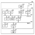
図1は、本発明の一実施形態に係る画像形成装置102の構成を示すブロック図である。
FIG. 1 is a block diagram illustrating a configuration of an
画像形成装置102は、外部装置から受信したプリントデータを装置内に一時的に蓄積し、ユーザによる当該プリントデータの印刷要求を受け取ることで印刷を実行する留め置き印刷(BOX印刷やプルプリント印刷)に対応したプリンタである。
The
また、画像形成装置102は、外部装置から受信したプリントデータに対して、受信後にプリントデータの印刷設定を変更可能なプリンタである。
The
また、画像形成装置102は、ユーザからの指示のもと、LAN103を経由してプリント指示とともにPDL(Page Description Language:ページ記述言語)で記述されたプリントデータ(PDLデータとも呼ぶ)を受信する。
Further, the
画像形成装置102は、プリントコントローラ110と、プリンタ装置111と、操作部113とを備える。
The
画像形成装置102は、プリントコントローラ110によって、受信したPDLデータを画像データ(ビットマップイメージ)に展開する。
The
画像形成装置102は、プリントコントローラ110によって展開された画像データを、プリンタ装置111で印刷用紙に印刷する。
The
プリントコントローラ110は、ネットワークI/F226を介してLAN103や公衆回線(WAN)(例えば、PSTNまたはISDN等)と接続し、外部装置との間で情報の入出力を行う。また、プリントコントローラ110は、操作部I/F225を介して操作部113と接続し、デバイスI/F232を介してプリンタ装置111と接続する。
The
また、プリントコントローラ110は、操作部113を介してユーザから入力された印刷要求に応じてプリントジョブを開始し、プリントデータから画像データを形成し、その画像データをプリンタ装置111に出力する。プリントジョブは、プリンタ装置111が画像データを印刷用紙に印刷することで終了する。
In addition, the
操作部113は、各種メニューや印刷データ情報等を表示可能な表示画面を有し、ユーザから、プリントコントローラ110で使用する印刷設定項目の変更を受け付け、プリントコントローラ110の操作部I/F225に渡す。また、操作部113は、プリントやコピーなどの画像形成装置102が備える各種サービスの実行に関する入力も受け付ける。操作部I/F225は、操作部113に対するインタフェース部であり、操作部113に対して操作画面データを出力する。また、操作部I/F225は、操作部113からユーザが入力した情報をプリントコントローラ110に伝える。
The
CPU220は画像形成装置102を制御するプロセッサである。
The
RAM222は、CPU220が動作するためのシステムワークメモリである。また、RAM222は、PDLデータ格納領域、中間データ格納領域、画像データ格納領域、測定データ格納領域、及び予測データ格納領域を備え、CPU220が実行するソフトウェアモジュールの処理結果を格納する。
The
ROM221は、画像形成装置102のブートプログラムや、操作部113、プリントコントローラ110、プリンタ装置111などの各種制御プログラムを格納する。
The
記憶装置223はハードディスクドライブとすることができ、各種処理のためのシステムソフトウェア及び入力された画像データ等を格納する。
The
イメージバスI/F228は、システムバス227と、画像データを高速で転送する画像バス230とを接続するインタフェースであり、データ構造を変換するバスブリッジである。画像バス230には、RIP(ラスタイメージプロセッサ)231、デバイスI/F232が接続される。RIP231は、プリントデータに含まれるPDLデータを解釈し、画像データ(ビットマップイメージ)に展開する。
The image bus I / F 228 is an interface that connects the
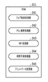
図2は、従来のROM221が格納するプログラムモジュールを示すブロック図である。
FIG. 2 is a block diagram showing program modules stored in the
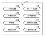
ROM221が格納するプログラムモジュールは、RAM222上に展開され、CPU220によって実行される。そうすることで、ROM221が格納するプログラムモジュールは、ジョブ制御処理部241、PDL解釈処理部242、RIP処理部243、時間予測処理部244、プリントデータ変更部245として機能する。
The program module stored in the
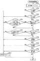
図3は、従来のプリントデータを留め置く処理に関するフローチャートを示す。ここでは、画像形成装置102が外部装置からプリントデータを受信し、当該プリントデータを留め置くまでの処理フローの一例を示す。ユーザからの印刷指示、または、あらかじめ画像形成装置102の設定に、プリントデータを留め置く(一時的に蓄積する)設定が含まれている。具体的には、BOX印刷やプルプリント印刷を行うことが、ユーザから印刷指示、または画像形成装置102に対して設定されている。
FIG. 3 shows a flowchart relating to a conventional process for retaining print data. Here, an example of a processing flow from when the
ステップS301において、画像形成装置102は、外部装置からPDLで記述されたプリントデータを受信する。具体的には、画像形成装置102のプリントコントローラ110が、LAN103に接続されたネットワークI/F226を介してプリントデータを受信する。受信したプリントデータは、RAM222のプリントデータ格納領域及び記憶装置223に格納される。
In step S301, the
ステップS302において、CPU220はジョブ制御処理を開始する。具体的には、CPU220が、ROM221に格納されたプログラムモジュールであるジョブ制御処理部241、PDL解釈処理部242、RIP処理部243、時間予測処理部244をRAM222に展開する。CPU220は、RAM222に展開したジョブ制御処理部241を実行することで、ジョブ制御処理を開始する。その他のPDL解釈処理部242、RIP処理部243、時間予測処理部244は、ジョブ制御処理部241によって間接的に制御され、実行される。
In step S302, the
ステップS303において、ジョブ制御処理部241は、PDL解釈処理部242を実行し、プリントデータのPDL解釈処理を開始する。
In step S303, the job
ステップS304において、PDL解釈処理部242は、RAM222のプリントデータ格納領域に格納されたプリントデータを解釈し、中間データを生成する。この中間データは、後続のRIP処理のために、実際のプリント処理で適用される解像度よりも低い解像度で生成される。例えば、実際のプリント処理で適用される解像度が600dpiであれば、600dpiよりも低い解像度(150dpi、75dpiなど)で生成される。PDL解釈処理部242は、生成した中間データをRAM222の中間データ格納領域に格納し、ジョブ制御処理部241に終了を通知する。
In step S304, the PDL
ステップS305において、ジョブ制御処理部241は、PDL解釈処理の終了を受けて、RIP処理部243を実行し、中間データのRIP処理を開始する。
In step S305, the job
ステップS306において、RIP処理部243は、RIP処理の開始時刻を取得してRAM222の測定データ格納領域に格納し、RIP231を用いて、RAM222の中間データ格納領域に格納された中間データに従って画像データを生成する。
In step S306, the
RIP処理部243が中間データに従って画像データを生成する手法としては、例えば、一般的に知られるスキャンライン手法がある。スキャンライン手法では、主走査方向のライン毎に陰面除去を行いながら画像データを生成し、前面に別オブジェクトが重なることで隠れるオブジェクトの領域の画像データの生成は行わない。このため、RIP処理部243は、まず、中間データを読み込み、ソート処理を実行して、スキャンライン単位で描画オブジェクト同士を正しい配置にする。次いで、RIP処理部243は、正しく配置された描画オブジェクトに対して色の割り当てを行い、描画オブジェクト同士の色をピクセル単位で合成する。スキャンライン手法では、このようにして画像データが生成される。
As a method for generating image data according to the intermediate data by the
次いで、RIP処理部243は、生成した画像データをRAM222の画像データ格納領域に格納する。画像データを格納すると、RIP処理部243は、ジョブ制御処理部241に終了を通知するとともに、RIP処理の終了時刻を取得してRAM222の測定データ格納領域に格納する。
Next, the
ステップS307において、ジョブ制御処理部241は、RIP処理の終了を受けて時間予測処理部244を実行し、時間予測処理を開始する。
In step S307, the job
ステップS308において、時間予測処理部244は、RAM222の測定データ格納領域に格納されたRIP処理の開始時刻と終了時刻の差から、RIP処理に掛かった時間を算出する。
In step S <b> 308, the time
前述したスキャンライン手法によるRIP処理において、ピクセル生成に関与する処理は解像度の変化に対して、処理時間がその変化の2乗に比例する。一方で、オブジェクトのソート処理は、解像度に依存しない描画オブジェクト同士の位置制御を行っており、プリントデータ毎に固有の処理時間を要する。そのため、RIP処理に掛かる時間は、x軸を解像度、y軸を処理時間とした場合にy = ax^2+bという関係式が成立する。パラメータ「a」及び「b」は、RAM222に格納された中間データと、中間データに対するRIP処理に掛かった時間から算出される。
In the RIP process using the scanline method described above, the process involved in pixel generation has a processing time proportional to the square of the change with respect to a change in resolution. On the other hand, the object sorting process controls the position of drawing objects independent of the resolution, and requires a specific processing time for each print data. Therefore, the time required for the RIP processing is expressed by the relation y = ax ^ 2 + b when the x-axis is the resolution and the y-axis is the processing time. The parameters “a” and “b” are calculated from the intermediate data stored in the
時間予測処理部244は、上記関係式から、実際のプリント処理で適用される解像度でのRIP処理時間である画像形成処理時間を予測し、予測データとしてRAM222の予測データ格納領域に格納する。このとき、算出したパラメータ「a」及び「b」も、RAM222の予測データ格納領域に格納する。時間予測処理部244は、予測データおよびパラメータを格納すると、ジョブ制御処理部241に終了を通知する。
The time
ステップS309において、ジョブ制御処理部241は、時間予測処理の終了を受けてジョブ制御処理を終了する。また、ジョブ制御処理部241は、RAM222の予測データ格納領域に格納された予測データを記憶装置223に、プリントデータと対応するように格納する。
In step S309, the job
以上説明したように、画像形成装置102は、外部装置から受信したプリントデータを処理して、実際のプリント処理で適用される解像度でのRIP処理時間である画像形成処理時間を予測し、プリントデータを留め置く。
As described above, the
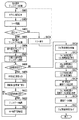
図4は、従来の留め置きプリントデータの印刷処理を示すフローチャートである。従来の処理では、留め置いたプリントデータの印刷設定が変更された場合、以下に説明するように、一律にRIP処理時間を予測し直している。 FIG. 4 is a flowchart showing a conventional print processing of reserved print data. In the conventional processing, when the print setting of the reserved print data is changed, the RIP processing time is uniformly re-estimated as described below.
ステップS401において、画像形成装置102は、ユーザからの指示(例えば、スリープ復帰)を受けて、操作部113にログイン画面を表示する。ログイン画面の表示は、CPU220が、ROM221に格納された操作部アプリケーションをRAM222に展開して実行し、操作部113を制御することによって行われる。
In step S <b> 401, the
ステップS402において、操作部アプリケーションを実行するCPU220は、ICカード等によるユーザ認証を行う。本実施形態において、ユーザ認証は重要なプロセスではないので、ここでは、認証カードの検出方法やICカードの識別ID取得方法や認証サーバによる認証処理といった詳細な説明は省略する。
In step S402, the
ステップS403において、操作部アプリケーションを実行するCPU220は、認証結果を判定し、認証エラーであった場合、ステップS404にて、エラー画面を操作部113に表示する。該エラー画面にてOKボタンが押下されると、処理はステップS401に戻り、再度、ログイン画面を表示する。一方、認証結果が認証成功であった場合、処理はステップS405へ進む。
In step S403, the
ステップS405において、操作部アプリケーションを実行するCPU220は、操作部113を介したユーザから指示に基づいて、留め置きされたプリントデータの印刷処理を実行する。
In step S <b> 405, the
ステップS406において、操作部アプリケーションを実行するCPU220は、操作部113に留め置きされたプリントデータの一覧を表示する。一覧として表示する項目には、文書名、プリントデータの受信日時、印刷設定に加え、図3のステップS308で算出した、プリントデータのRIP処理の予測時間を適用した印刷処理の予測時間が含まれる。
In step S <b> 406, the
ステップS407において、操作部アプリケーションを実行するCPU220は、操作部113に表示した留め置きプリントデータ一覧画面を介して、印刷するプリントデータの選択を受け付ける。
In step S <b> 407, the
ステップS408において、操作部アプリケーションを実行するCPU220は、操作部113に、選択されたプリントデータをこのまま印刷するか、または、印刷設定の変更を行うかのいずれかをユーザが選択可能な画面を表示する。この画面には、留め置きプリントデータ一覧画面と同様の表示項目が含まれる。よって、表示項目には、選択されたプリントデータの文書名、プリントデータの受信日時、印刷設定に加え、図3のステップS308で予測した、プリントデータのRIP処理の予測時間を適用した印刷処理の予測時間が含まれる。
In step S <b> 408, the
プリントデータの印刷が選択された場合、処理は、ステップS414に進み、印刷設定の変更が選択された場合、処理は、ステップS409へ進む。 If printing of print data is selected, the process proceeds to step S414, and if changing print settings is selected, the process proceeds to step S409.
ステップS409において、操作部アプリケーションを実行するCPU220は、操作部113に印刷設定変更画面を表示する。変更可能な印刷設定項目には、カラーモードの設定、ページ集約の設定、集約したページの配置設定、印刷部数の指定、地紋・スタンプの設定、解像度の設定、出力用紙サイズの設定、白紙節約の設定、両面・片面の指定等が含まれる。
In step S409, the
カラーモードの設定は、モノクロ印刷とカラー印刷のどちらかを指定する。ページ集約の設定は、例えば4ページを1ページに割り付けるような印刷設定(4in1、以後、Nページを1ページに割り付けるような印刷設定をNin1と称する)を指定する。集約したページの配置設定は、Nin1が設定されたプリントデータの印刷用紙への配置を指定する。印刷部数の指定は、プリントデータの印刷部数を指定する。地紋・スタンプの設定は、印刷用紙上に、地紋や日付などのスタンプの印字を指定する。解像度の設定は、600dpiや1200dpiといった、プリンタ装置111の性能に応じた印刷解像度を指定する。出力用紙サイズの設定は、印刷用紙を指定する。白紙節約の設定は、プリントデータの白紙となっているページを削除するかどうかを指定する。両面・片面の指定は、片面、両面(長辺綴じ)、両面(短辺綴じ)を指定する。
The color mode setting specifies either monochrome printing or color printing. As the page aggregation setting, for example, a print setting for assigning 4 pages to one page (4 in 1, hereinafter, a print setting for assigning N pages to 1 page is designated as Nin 1) is specified. The arrangement setting of the aggregated pages designates the arrangement of the print data for which Nin1 is set on the printing paper. The designation of the number of print copies designates the number of print data print copies. The setting of a background pattern / stamp specifies printing of a stamp such as a background pattern or a date on a printing paper. The resolution setting specifies a print resolution according to the performance of the
ステップS410において、操作部アプリケーションを実行するCPU220は、ユーザによる印刷設定変更の完了を受け付ける。
In step S410, the
ステップS411において、操作部アプリケーションを実行するCPU220は、印刷設定が変更されたかどうかを判定する。印刷設定が変更されていない場合はステップS408へ戻る。一方、印刷設定が変更された場合はステップS412へ進む。
In step S411, the
ステップS412において、CPU220は、ROM221のプリントデータ変更部245をRAM222に展開して実行し、プリントデータ変更処理を実行する。具体的には、選択されたプリントデータを、ユーザが変更した印刷設定に応じたプリントデータに編集する。
In step S412, the
ステップS413において、CPU220は、編集したプリントデータのRIP処理時間を予測する。ステップS413における処理は、図3に示したステップS302からステップS309の処理と同様の処理であり、説明を省略する。RIP処理時間を予測すると、処理はステップS408に戻る。
In step S413, the
ステップS408においてプリントデータの印刷が選択されると、処理は、ステップS414に進む。 If printing of print data is selected in step S408, the process proceeds to step S414.
ステップS414において、CPU220はジョブ制御処理を開始する。具体的には、CPU220が、ROM221に格納されたプログラムモジュールであるジョブ制御処理部241、PDL解釈処理部242、RIP処理部243、時間予測処理部244をRAM222に展開する。CPU220は、RAM222に展開したジョブ制御処理部241を実行することで、ジョブ制御処理を開始する。
In step S414, the
ステップS415において、ジョブ制御処理部241は、記憶装置223に格納されたプリントデータをRAM222に展開し、PDL解釈処理部242を実行することで、プリントデータのPDL解釈処理を開始する。
In step S415, the job
ステップS416において、PDL解釈処理部242は、RAM222のプリントデータ格納領域に格納されたプリントデータを解釈し、中間データを生成する。ここで生成される中間データは、図3のステップS304で生成された中間データとは異なり、実際のプリント処理で適用される解像度で生成される。
In step S416, the PDL
次いで、PDL解釈処理部242は、生成した中間データをRAM222の中間データ格納領域に格納し、ジョブ制御処理部241に終了を通知する。
Next, the PDL
ステップS417において、ジョブ制御処理部241は、PDL解釈処理の終了の通知を受けて、RIP処理部243を実行し、RIP処理を開始する。
In step S417, the job
ステップS418において、RIP処理部243は、RIP231を用いて、RAM222の中間データ格納領域に格納された中間データに従って画像データ(ビットマップイメージ)を生成する。RIP処理部243は、生成した画像データをRAM222の画像データ格納領域に格納し、ジョブ制御処理部241に終了を通知する。
In step S418, the
ステップS419において、ジョブ制御処理部241は、プリンタ装置111に対して、RAM222の画像データ格納領域に格納された画像データの印刷を指示する。
In step S <b> 419, the job
ステップS420において、プリンタ装置111はRAM222の画像データ格納領域に格納された画像データを、印刷用紙に印刷し排紙する。排紙が完了するとプリンタ装置111は、ジョブ制御処理部241に印刷の終了を通知する。
In step S <b> 420, the
ステップS421において、ジョブ制御処理部241は、プリンタ装置111からの印刷処理終了の通知を受けてジョブ制御処理を終了し、操作部113に終了通知を表示する。印刷が終了したプリントデータについては、印刷終了後に削除してもよいし、ユーザが削除を指示するまで記憶装置223に格納してもよい。記憶装置223に格納された予測データは、対応するプリントデータを削除する際に削除する。
In step S <b> 421, the job
図4のステップS413で示したように、RIP処理時間の予測処理は、ユーザが印刷設定を変更するたびに実行される。そのため、ユーザは、RIP処理時間の予測処理が完了するまで、次の操作を行うことができなかった。 As shown in step S413 of FIG. 4, the RIP processing time prediction process is executed every time the user changes the print setting. Therefore, the user cannot perform the next operation until the prediction process of the RIP processing time is completed.
(第1の実施形態)
次に、本発明の第1の実施形態について説明する。本実施形態によると、従来の留め置きプリントデータの印刷処理における、RIP処理時間の予測処理に要する時間を短縮することができる。
(First embodiment)
Next, a first embodiment of the present invention will be described. According to the present embodiment, it is possible to reduce the time required for the prediction process of the RIP processing time in the conventional print process of reserved print data.
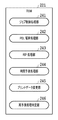
図5は、本発明の一実施例に係るROM221が格納するプログラムモジュールを示すブロック図である。ROM221は、図2に示したプログラムモジュールに加えて、再予測処理判定部246を備える。
FIG. 5 is a block diagram showing program modules stored in the
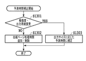
図6は、本発明の一実施形態に係る留め置きプリントデータの印刷処理を示すフローチャートである。図6のステップS601からステップS612については、図4のステップS401からステップS412に対応する。また、図6のステップS615からステップS623については、図4のステップS413からステップS421に対応する。そのため、図4に対応するステップの説明は省略する。図6のステップS613とステップS614が、従来の留め置きプリントデータの印刷処理に対して追加された処理である。 FIG. 6 is a flowchart showing a printing process of reserved print data according to an embodiment of the present invention. Steps S601 to S612 in FIG. 6 correspond to steps S401 to S412 in FIG. Also, Steps S615 to S623 in FIG. 6 correspond to Steps S413 to S421 in FIG. Therefore, the description of the steps corresponding to FIG. 4 is omitted. Steps S613 and S614 in FIG. 6 are processes added to the conventional print processing of reserved print data.
ステップS612においてプリントデータの編集が完了すると、ステップS613において、CPU220はRAM222に展開された再予測処理判定部246を実行し、再予測処理判定を開始する。再予測処理判定部246は、編集したプリントデータのRIP処理時間を再予測する必要があるかどうかを判定する。判定処理の詳細は、図7を参照して後述する。
When the editing of the print data is completed in step S612, in step S613, the
ステップS614において、再予測処理判定部246は、ステップS613の判定結果が「再予測しない(再予測実行フラグがFalse)」の場合は、ステップS608に戻る。この場合、RIP処理時間を再予測しないので、既に算出され、記憶されている予測時間が表示され、ユーザに通知される。一方、ステップS613の判定結果が「再予測する(再予測実行フラグがTrue)」の場合は、ステップS615に進み、RIP処理時間を再予測する。
In step S614, the re-prediction
このように、本実施形態では、S613の判定結果に応じて、RIP処理時間を再予測するかどうかを切り替えることができる。 Thus, in this embodiment, whether to re-predict the RIP processing time can be switched according to the determination result of S613.
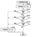
図7は、図6のステップS613における再予測処理判定のフローチャートである。再予測処理判定では、ユーザから受け付けた印刷設定変更が、プリントデータの描画内容を変更し、RIP処理時間に影響する変更であるかどうかを判定する。印刷設定変更のうち、印刷部数の指定、両面・片面の指定は、プリントデータの描画内容を変更しない。よって、これらの設定変更は、RIP処理時間に影響せず、使用する印刷用紙の種類と部数に対して変化が一定であるため、再予測処理は不要である。一方、カラーモードの設定、ページ集約の設定、集約したページの配置設定、地紋・スタンプの設定、解像度の設定、出力用紙サイズの設定、白紙節約の設定が変更されると、プリントデータの描画内容が変更される。よって、これらの設定変更は、RIP処理時間に影響するため、再予測処理が必要となる。 FIG. 7 is a flowchart of the re-prediction process determination in step S613 in FIG. In the re-prediction processing determination, it is determined whether or not the print setting change received from the user is a change that affects the RIP processing time by changing the drawing content of the print data. Among print setting changes, designation of the number of copies to be printed and designation of double-sided / single-sided do not change the drawing content of the print data. Therefore, these setting changes do not affect the RIP processing time, and the change is constant with respect to the type and the number of copies of the printing paper to be used, so that the re-prediction processing is unnecessary. On the other hand, when the color mode setting, page aggregation setting, aggregated page layout setting, tint block / stamp setting, resolution setting, output paper size setting, blank page saving setting are changed, the print data drawing contents Is changed. Therefore, since these setting changes affect the RIP processing time, re-prediction processing is necessary.
まず、ステップS701において、再予測処理判定部246は、再予測実行フラグをFalseにする。
First, in step S701, the re-prediction
ステップS702において、再予測処理判定部246は、ページ集約の設定が変更されたかどうかを判定する。変更があった場合は、ステップS711に進み、再予測実行フラグをTrueにする。
In step S702, the re-prediction
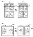
図8は、ページ集約の設定変更に伴う、スキャンライン上のオブジェクトの数と位置の変化を示す図である。 FIG. 8 is a diagram illustrating changes in the number and positions of objects on the scan line in accordance with the change in the page aggregation setting.
図8に示すように2枚のプリントデータ121、122を1枚のプリントデータ123に集約する場合、排紙方向に対してプリントデータの向きが変わる。このためスキャンラインレンダリングを用いたRIP231では、スキャンライン124、125上に存在するページ内オブジェクトの数や位置関係も変わる。したがって、ページ集約の設定が変更されると、前述したスキャンライン毎のオブジェクトのソート処理や陰面除去処理が印刷設定を変更する前と比べて変わるため、再予測処理が必要となる。
As shown in FIG. 8, when two
一方、ページ集約の設定に変更がなかった場合は、ステップS703に進む。 On the other hand, if there is no change in the page aggregation setting, the process advances to step S703.
ステップS703において、再予測処理判定部246は、カラーモードの設定が変更されたかどうかを判定する。変更があった場合は、ステップS711に進み、再予測実行フラグをTrueにする。
In step S703, the re-prediction
カラーモードの設定変更では、色のチャンネル数とそれに伴う色指定に必要なデータサイズが異なる。このため、色の合成に必要な処理負荷や生成される中間データ、画像形成処理内容が変わるため、再予測処理が必要となる。 When the color mode setting is changed, the number of color channels and the data size required for color designation are different. For this reason, the processing load necessary for color synthesis, the intermediate data to be generated, and the content of the image forming process are changed, so that a re-prediction process is necessary.
一方、カラーモードの設定に変更がなかった場合は、ステップS704に進む。 On the other hand, if there is no change in the color mode setting, the process advances to step S704.
ステップS704において、再予測処理判定部246は、印刷ページの配置順の設定が変更されたかどうかを判定する。変更があった場合は、ステップS705に進む。一方、変更がなかった場合は、ステップS706に進む。
In step S704, the re-prediction
図9(A)は、4in1(4ページを1ページに集約)における印刷ページの配置順の設定変更に伴う、プリントデータの変化を示す図である。変更前の印刷ページの配置例126と、変更後の印刷ページの配置例127とを比較すると、スキャンライン128、129上に存在するページ内オブジェクト数や位置関係が変わる。
FIG. 9A is a diagram illustrating a change in print data in accordance with a change in the arrangement order of print pages in 4in1 (4 pages are combined into one page). When the print page layout example 126 before the change is compared with the print page layout example 127 after the change, the number of objects in the page and the positional relationship existing on the
印刷ページの配置順の設定に変更があった場合、さらにステップS705において、再予測処理判定部246が、複数ページを1ページに集約した設定において、印刷ページの配置順がスキャンライン方向にのみ変更されたかどうかを判定する。スキャンライン方向のみの変更でなかった場合は、ステップS711に進み、再予測実行フラグをTrueにする。一方、スキャンライン方向のみの変更であった場合は、ステップS706に進む。
If there is a change in the print page arrangement order, in step S705, the re-prediction
図9(B)は、2in1(2ページを1ページに集約)における印刷ページの配置順の設定変更に伴うプリントデータの変化を示す図である。変更前の印刷ページの配置例130と、変更後の印刷ページの配置例131とを比較すると、スキャンライン132、133上に存在するページ内オブジェクト数やソート処理に影響する位置関係に変化はない。したがって、印刷ページの配置順の設定に変更があった場合でも、1枚のプリントデータ内のスキャンライン方向にのみページの配置順を入れ替える変更だった場合には、再予測処理を実行する必要はない。
FIG. 9B is a diagram illustrating a change in print data in accordance with a setting change of the arrangement order of print pages in 2 in 1 (2 pages are combined into 1 page). Comparing the print page arrangement example 130 before the change with the print page arrangement example 131 after the change, there is no change in the number of objects in the page existing on the
ステップS706において、再予測処理判定部246は、地紋・スタンプ設定が変更されたかどうかを判定する。変更があった場合は、ステップS707に進む。一方、変更がなかった場合は、ステップS708に進む。地紋・スタンプ設定が変更されると、ページ全面に合成処理が必要になるため再予測処理が必要となる。
In step S706, the re-prediction
しかしながら、地紋・スタンプ設定に変更があった場合は、さらにステップS707において、再予測処理判定部246は、その影響度が所定の閾値以下であるかどうかを判定する。具体的には、地紋・スタンプ設定の変更に伴い、付加・削除される領域が所定の閾値(例えば、プリントデータの0.1%)を超えた場合は、ステップS711に進み、再予測実行フラグをTrueにする。一方、所定の閾値以下であった場合は、ステップS708に進む。地紋・スタンプ設定に変更があった場合でも、その影響度が所定の閾値以下、例えば、付加・削除される領域がプリントデータの0.1%以下である場合は、RIP処理時間に大きく影響しないため、再予測処理を必要としない。
However, if the copy-forgery-inhibited pattern / stamp setting is changed, in step S707, the re-prediction
ステップS708において、再予測処理判定部246は、解像度の設定が変更されたかどうかを判定する。変更があった場合は、ステップS711に進み、再予測実行フラグをTrueにする。一方、変更がなかった場合は、ステップS709に進む。
In step S708, the re-prediction
ステップS709において、再予測処理判定部246は、出力用紙の設定が変更されたかどうかを判定する。変更があった場合は、ステップS711に進み、再予測実行フラグをTrueにする。一方、変更がなかった場合は、ステップS710に進む。
In step S709, the re-prediction
解像度の設定、および出力用紙の設定が変更されると、画像形成処理後の出力画像サイズが変わる。加えて、出力用紙の向き(例えば、縦・横)が変更される場合、スキャンライン上に存在するページ内オブジェクトの数や位置が変わるため、再予測が必要となる。 When the resolution setting and the output paper setting are changed, the output image size after the image forming process is changed. In addition, when the orientation (for example, portrait / landscape) of the output paper is changed, the number and position of the objects in the page existing on the scan line change, and thus re-prediction is necessary.
ステップS710において、再予測処理判定部246は、白紙節約の設定が変更されたかどうかを判定する。変更があった場合は、ステップS711に進み、再予測実行フラグをTrueにする。
In step S710, the re-prediction
白紙節約の設定が変更され、白紙ページの追加または削除が行われる場合、スキャンライン上に存在するページ内オブジェクトの数や位置が変わるため、再予測が必要となる。 When the blank page saving setting is changed and a blank page is added or deleted, the number and position of the objects in the page existing on the scan line change, and thus re-prediction is necessary.
一方、変更がなかった場合は、再予測処理判定を終了する。 On the other hand, when there is no change, the re-prediction process determination is terminated.
ステップS711において、再予測処理判定部246は、再予測実行フラグをTrueにして、再予測処理判定を終了する。
In step S711, the re-prediction
以上説明したように、本実施形態によると、留め置きプリントデータの印刷設定の変更があった場合に、その変更内容を詳細に判定し、再予測処理が必要のない印刷設定の変更を判定する。そうすることで、変更された印刷設定に応じて、再予測処理を行うかどうかを切り替え、必要のない無駄な予測処理を削減することができる。 As described above, according to the present embodiment, when there is a change in the print setting of the reserved print data, the change content is determined in detail, and a change in the print setting that does not require re-prediction processing is determined. By doing so, it is possible to switch whether or not to perform re-prediction processing according to the changed print setting, and to reduce unnecessary prediction processing that is not necessary.
(第2の実施形態)
次いで、本発明の第2の実施形態について説明する。上述した第1の実施形態では、RIP処理時間に影響を与える印刷設定変更があった場合にのみ、RIP処理時間を予測しなおすものであった。それに対し、本実施形態では、印刷設定の変更がRIP処理時間に影響するものであっても、再予測処理を行わずに、既に算出されている予測時間を補正する。そうすることによって、RIP処理時間の予測処理を削減することができる。
(Second Embodiment)
Next, a second embodiment of the present invention will be described. In the first embodiment described above, the RIP processing time is re-estimated only when there is a print setting change that affects the RIP processing time. On the other hand, in this embodiment, even if a change in print settings affects the RIP processing time, the predicted time already calculated is corrected without performing the re-prediction processing. By doing so, the prediction process of RIP processing time can be reduced.
図10は、本発明の一実施形態に係るROM221が格納するプログラムモジュールを示すブロック図である。ROM221は、図5に示したプログラムモジュールに加えて、予測時間補正判定部247、及び予測時間補正部248を備える。
FIG. 10 is a block diagram showing program modules stored in the
図11は、本発明の一実施形態に係る留め置きプリントデータの印刷処理を示すフローチャートである。図11のステップS1101からステップS1114については、図6のステップS601からステップS614に対応する。また、図11のステップS1118からステップS1126については、図6のステップS615からステップS623に対応する。そのため、図6に対応するステップの説明は省略する。図11のステップS1115からステップS1117が、第1の実施形態に対して追加された処理である。 FIG. 11 is a flowchart showing a printing process of reserved print data according to an embodiment of the present invention. Steps S1101 to S1114 in FIG. 11 correspond to steps S601 to S614 in FIG. Further, Steps S1118 to S1126 in FIG. 11 correspond to Steps S615 to S623 in FIG. Therefore, the description of the steps corresponding to FIG. 6 is omitted. Steps S1115 to S1117 in FIG. 11 are processes added to the first embodiment.
ステップS1114において再予測を実行する必要があると判定された場合、ステップS1115において、CPU220はRAM222に展開された予測時間補正判定部247を実行し、予測時間補正判定を実行する。判定処理の詳細は、図12を参照して後述する。
If it is determined in step S1114 that re-prediction needs to be executed, in step S1115, the
ステップS1116において、予測時間補正判定部247は、予測したRIP処理時間を補正できると判定された場合、ステップS1117に進む。具体的には、後述する予測時間補正フラグがTrueである場合に、ステップS1117に進む。ステップS1117では、CPUはRAM222に展開された予測時間補正部248を実行し、予測時間補正を行う。一方、予測したRIP処理時間を補正できないと判定された場合は、ステップS1118に進み、RIP処理時間を再予測する。
In step S1116, if it is determined that the predicted RIP processing time can be corrected, the predicted time
図12は、図11のステップS1115における予測時間補正判定のフローチャートである。 FIG. 12 is a flowchart of the prediction time correction determination in step S1115 of FIG.
まず、ステップS1201において、予測時間補正判定部247は、予測時間補正フラグをFalseにする。
First, in step S1201, the prediction time
ステップS1202において、予測時間補正判定部247は、解像度の設定が変更されたかどうかを判定する。変更があった場合は、ステップS1205に進み、予測時間補正フラグをTrueにする。一方、変更がなかった場合は、S1203に進む。
In step S1202, the predicted time
ステップS1203において、予測時間補正判定部247は、出力用紙の設定が変更されたかどうかを判定する。変更があった場合は、ステップS1205に進み、予測時間補正フラグをTrueにする。一方、変更がなかった場合は、S1204に進む。
In step S1203, the predicted time
ステップS1204において、予測時間補正判定部247は、白紙節約の設定が変更されたかどうかを判定する。変更があった場合は、ステップS1205に進み、予測時間補正フラグをTrueにする。一方、変更がなかった場合は、再予測処理判定を終了する。
In step S1204, the predicted time
ステップS1205において、予測時間補正判定部247は、予測時間補正フラグをTrueにし、予測時間補正判定を終了する。
In step S1205, the predicted time
このように、プリントデータの印刷設定が変更された場合でも、それが、解像度の設定、出力用紙の設定、または、白紙節約の設定であった場合には、予測時間補正フラグをTrueにして、再予測処理を行わずに、後述する予測時間補正処理を行う。 As described above, even when the print setting of the print data is changed, if the setting is the resolution setting, the output paper setting, or the blank page saving setting, the prediction time correction flag is set to True, The prediction time correction process described later is performed without performing the re-prediction process.
図13は、図11のステップS1117における予測時間補正のフローチャートである。 FIG. 13 is a flowchart of the prediction time correction in step S1117 of FIG.
まず、ステップS1301において、予測時間補正部248は、解像度または出力用紙の設定が変更されたかどうかを判定する。解像度または出力用紙の設定に変更があった場合は、ステップS1303に進む。一方、解像度または出力用紙の設定に変更がなかった場合、すなわち、白紙節約の設定に変更があった場合は、ステップS1302に進む。
First, in step S1301, the predicted
解像度が変更された場合や、出力用紙の縦横を変えずに、用紙サイズのみが変更された場合(例えば、A4用紙をA3用紙に変更する場合)は、変更された解像度に合わせてRIP処理時間を補正することができる。そのためステップS1303において、予測時間補正部248は、予測データ格納領域に格納されたパラメータ「a」及び「b」と、変更された解像度xを、前述した数式y = ax^2+bにあてはめ、処理時間yを求めることで、RIP処理時間を補正する。
When the resolution is changed, or when only the paper size is changed without changing the vertical and horizontal directions of the output paper (for example, when A4 paper is changed to A3 paper), the RIP processing time is adjusted according to the changed resolution. Can be corrected. Therefore, in step S1303, the prediction
一方、白紙節約の設定が変更された場合は、対象となる白紙ページの処理時間のみを算出し、当該ページの処理時間の追加/削除を行う。そのためステップS1302において、予測時間補正部248は、対象となる白紙ページの処理時間のみを算出し、当該ページの処理時間の追加/削除を行うことで、RIP処理時間を補正する。
On the other hand, when the blank page saving setting is changed, only the processing time of the target blank page is calculated, and the processing time of the page is added / deleted. Therefore, in step S1302, the prediction
なお、図11、図12、及び図13を参照して予測時間補正判定及び予測時間補正をそれぞれ独立して説明したが、印刷設定の変更内容に基づいてこれらの処理を同時に実行してもよい。 Although the prediction time correction determination and the prediction time correction have been described independently with reference to FIGS. 11, 12, and 13, these processes may be executed simultaneously based on the change contents of the print settings. .
以上に述べたように、解像度、出力用紙、白紙節約の設定の変更について、再予測処理を行わずに、印刷設定変更前の予測時間を補正することで、予測時間の算出時間短縮効果を得ることができる。 As described above, it is possible to obtain a prediction time calculation time shortening effect by correcting the prediction time before changing the print setting without performing the re-prediction processing for the change in the resolution, output paper, and blank page saving setting. be able to.
(第3の実施形態)
次いで、本発明の第3の実施形態について説明する。本実施形態においては、ユーザによる印刷設定変更が繰り返し実行された場合に、印刷設定内容と対応する予測時間を保持しておくことで、同様の設定が繰り返し発生した場合の予測時間の算出時間を短縮する。
(Third embodiment)
Next, a third embodiment of the present invention will be described. In the present embodiment, when the print setting change by the user is repeatedly executed, the prediction time corresponding to the print setting content is held, so that the calculation time of the predicted time when the same setting occurs repeatedly is calculated. Shorten.
図14は、本発明の一実施形態に係るROM221が格納するプログラムモジュールを示すブロック図である。ROM221は、図10のプログラムモジュールに加え、予測時間記憶部249、及び、予測時間変更部250を備える。
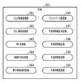
FIG. 14 is a block diagram showing program modules stored in the
本実施形態に係る処理のフローチャートは、図11のフローチャートの内、ステップS1113の再予測処理判定、ステップS1117の予測時間補正、およびステップS1118のRIP時間予測処理の内部処理が異なる以外は、図11に対応する。そのため、異なる処理のみを説明する。 The flowchart of the process according to the present embodiment is different from the flowchart of FIG. 11 except that the internal process of the re-prediction process determination in step S1113, the prediction time correction in step S1117, and the RIP time prediction process in step S1118 is different. Corresponding to Therefore, only different processes will be described.
本実施形態において、RAM222の予測データ格納領域に格納される予測データは、当該予測データを算出した際の印刷設定と対になる表の形で格納される。
In the present embodiment, the prediction data stored in the prediction data storage area of the
図15は、本実施形態においてRAM222の予測データ格納領域に格納される表500の一例を示す。予測時間記憶部249は、表500の形で、プリントデータ501、ページ集約の設定(Nup設定)502、カラーモード設定503、集約したページの配置設定504、地紋・スタンプ設定505を設定毎に保持する。また、予測時間記憶部249は、解像度設定506、出力用紙設定507、白紙節約設定508、予測時間509、該予測時間509を補正するために、解像度と処理時間の関係式に必要なパラメータ「a」510及び「b」511を設定毎に保持する。ステップS1117の予測時間補正とステップS1118のRIP時間予測処理において、各処理を実行するCPU220は、予測したRIP処理時間と印刷設定を予測データ格納領域の表500に追加する。
FIG. 15 shows an example of a table 500 stored in the predicted data storage area of the
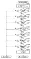
図16は、本実施形態におけるステップS1113の再予測処理判定において、図7のフローチャートで示した処理の前に実行される処理のフローチャートを示す。再予測処理判定部246は、変更された印刷設定項目の組み合わせが、予測データ格納領域の表500に存在するかどうかを判定する。
FIG. 16 shows a flowchart of processing executed before the processing shown in the flowchart of FIG. 7 in the re-prediction processing determination in step S1113 in the present embodiment. The re-prediction
まず、ステップS1601において、再予測処理判定部246は、再予測実行フラグをFalseにする。
First, in step S1601, the re-prediction
ステップS1602において、再予測処理判定部246は、印刷設定が変更された印刷データと同じ印刷データについて、ページ集約の設定と同じ設定が、表500に存在するかどうかを判定する。存在した場合は、ステップS1603に進む。一方、存在しなかった場合は、図7のステップS701に進む。
In step S1602, the re-prediction
ステップS1603において、再予測処理判定部246は、印刷設定が変更された印刷データと同じ印刷データについて、カラーモードの設定と同じ設定が、表500に存在するかどうかを判定する。存在した場合は、ステップS1604に進む。一方、存在しなかった場合は、図7のステップS701に進む。
In step S1603, the re-prediction
ステップS1604において、再予測処理判定部246は、印刷設定が変更された印刷データと同じ印刷データについて、集約したページの配置設定と同じ設定が、表500に存在するかどうかを判定する。存在した場合は、ステップS1605に進む。一方、存在しなかった場合は、図7のステップS701に進む。
In step S1604, the re-prediction
ステップS1605において、再予測処理判定部246は、印刷設定が変更された印刷データと同じ印刷データについて、地紋・スタンプ設定と同じ設定が、表500に存在するかどうかを判定する。存在した場合は、ステップS1606に進む。一方、存在しなかった場合は、図7のステップS701に進む。
In step S1605, the re-prediction
ステップS1606において、再予測処理判定部246は、印刷設定が変更された印刷データと同じ印刷データについて、解像度の設定と同じ設定が、表500に存在するかどうかを判定する。存在した場合は、ステップS1607に進む。一方、存在しなかった場合は、図7のステップS701に進む。
In step S1606, the re-prediction
ステップS1607において、再予測処理判定部246は、印刷設定が変更された印刷データと同じ印刷データについて、出力用紙の設定と同じ設定が、表500に存在するかどうかを判定する。存在した場合は、ステップS1608に進む。一方、存在しなかった場合は、図7のステップS701に進む。
In step S1607, the re-prediction
ステップS1608において、再予測処理判定部246は、印刷設定が変更された印刷データと同じ印刷データについて、白紙節約の設定と同じ設定が、表500に存在するかどうかを判定する。存在した場合は、ステップS1609に進む。一方、存在しなかった場合は、図7のステップS701に進む。
In step S1608, the re-prediction
表500に、上述した印刷設定項目のすべてが同じ印刷設定データが存在した場合は、ステップS1609において、予測時間変更部250が、表500の当該印刷設定データにおける予測時間509を参照する。参照したRIP処理時間の予測時間509を、操作部アプリケーションは、操作部113に表示する。次いで処理は、図11のステップS1114に進む。
If the table 500 includes print setting data that has the same print setting items as described above, the predicted
以上に述べたように、同じ印刷設定が繰り返し実行された場合、印刷設定とその予測時間を保持しておき、保存した印刷設定における予測時間を呼び出すことで、RIP処理時間を予測する必要が無くなり、無駄な予測処理を削減することができる。 As described above, when the same print setting is repeatedly executed, it is not necessary to predict the RIP processing time by holding the print setting and its estimated time and calling the estimated time in the saved print setting. , Wasteful prediction processing can be reduced.
なお、図11のステップS1117の予測時間補正処理においても同様に、表500を参照して、解像度の設定、出力用紙の設定、または、白紙節約の設定以外の印刷設定項目のすべてが同じ印刷データが存在した場合には、次の処理をしてもよい。すなわち、予測データ格納領域に格納されている当該印刷設定データにおける予測時間509、予測パラメータa510、予測パラメータb511を用いて補正をしてもよい。
Similarly, in the predicted time correction process in step S1117 of FIG. 11, the print data is the same for all print setting items other than the resolution setting, the output paper setting, or the blank page saving setting with reference to the table 500. If there is, the following processing may be performed. That is, correction may be performed using the
なお、本実施形態は第2の実施形態を利用する形態について説明したが、第1の実施形態を利用する形態であってもよい。 In addition, although this embodiment demonstrated the form using 2nd Embodiment, the form using 1st Embodiment may be sufficient.
(その他の実施例)
また、本発明は、以下の処理を実行することによっても実現される。即ち、上述した実施形態の機能を実現するソフトウェア(プログラム)を、ネットワーク又は各種記憶媒体を介してシステム或いは装置に供給し、そのシステム或いは装置のコンピュータ(またはCPUやMPU等)がプログラムを読み出して実行する処理である。
(Other examples)
The present invention can also be realized by executing the following processing. That is, software (program) that realizes the functions of the above-described embodiments is supplied to a system or apparatus via a network or various storage media, and a computer (or CPU, MPU, or the like) of the system or apparatus reads the program. It is a process to be executed.
Claims (12)
前記格納されたプリントデータの印刷設定の変更を受け付ける受け付け手段と、
前記変更された印刷設定が、前記プリントデータの描画内容を変更する設定かどうかを判定する判定手段と、
前記プリントデータの描画内容を変更する設定であると判定された場合に、画像形成処理時間を予測する予測手段と
を備えたことを特徴とする画像形成装置。 Storage means for storing print data and image formation processing time of the print data;
Accepting means for accepting a change in print settings of the stored print data;
A determination unit for determining whether the changed print setting is a setting for changing a drawing content of the print data;
An image forming apparatus comprising: a predicting unit that predicts an image forming processing time when it is determined that the drawing content of the print data is changed.
前記変更された印刷設定が、前記格納されたプリントデータの画像形成処理時間を補正することができる設定かどうか判定する判定手段と、
前記格納されたプリントデータの画像形成処理時間を補正することができる設定であると判定された場合に、前記格納されたプリントデータの画像形成処理時間を補正する補正手段と
をさらに備えたことを特徴とする請求項1に記載の画像形成装置。 When it is determined that the changed print setting is a setting for changing the drawing content of the print data,
Determining means for determining whether the changed print setting is a setting capable of correcting an image forming processing time of the stored print data;
And a correction unit that corrects the image formation processing time of the stored print data when it is determined that the setting is capable of correcting the image formation processing time of the stored print data. The image forming apparatus according to claim 1, wherein:
前記保持された印刷設定と同じ印刷設定が発生した場合に、前記保持された画像形成処理時間に基づいて、画像形成処理時間を変更する変更手段と
をさらに備えたことを特徴とする請求項1に記載の画像形成装置。 Storage means for holding the changed print setting and the image forming processing time corresponding to the changed print setting;
2. The image processing apparatus according to claim 1, further comprising: a changing unit configured to change the image forming process time based on the held image forming process time when the same print setting as the held print setting occurs. The image forming apparatus described in 1.
前記格納されたプリントデータの印刷設定の変更を受け付ける受け付け手段と、
前記変更された印刷設定に応じて、前記画像形成処理時間の予測方法を切り替える切り替え手段と
を備えたことを特徴とする画像形成装置。 Storage means for storing print data and image formation processing time of the print data;
Accepting means for accepting a change in print settings of the stored print data;
An image forming apparatus comprising: a switching unit that switches a prediction method of the image forming processing time according to the changed print setting.
前記格納されたプリントデータの印刷設定の変更を受け付けるステップと、
前記変更された印刷設定が、前記プリントデータの描画内容を変更する設定かどうかを判定するステップと、
前記プリントデータの描画内容を変更する設定であると判定された場合に、画像形成処理時間を予測するステップと
を含むことを特徴とする画像形成方法。 Storing print data and an image formation processing time of the print data;
Receiving a change in print settings of the stored print data;
Determining whether the changed print setting is a setting for changing a drawing content of the print data; and
And a step of predicting an image forming processing time when it is determined that the setting is to change the drawing content of the print data.
Priority Applications (1)
| Application Number | Priority Date | Filing Date | Title |
|---|---|---|---|
| JP2014046526A JP2015168224A (en) | 2014-03-10 | 2014-03-10 | Image forming device, image forming method, and program |
Applications Claiming Priority (1)
| Application Number | Priority Date | Filing Date | Title |
|---|---|---|---|
| JP2014046526A JP2015168224A (en) | 2014-03-10 | 2014-03-10 | Image forming device, image forming method, and program |
Publications (2)
| Publication Number | Publication Date |
|---|---|
| JP2015168224A true JP2015168224A (en) | 2015-09-28 |
| JP2015168224A5 JP2015168224A5 (en) | 2017-04-20 |
Family
ID=54201391
Family Applications (1)
| Application Number | Title | Priority Date | Filing Date |
|---|---|---|---|
| JP2014046526A Pending JP2015168224A (en) | 2014-03-10 | 2014-03-10 | Image forming device, image forming method, and program |
Country Status (1)
| Country | Link |
|---|---|
| JP (1) | JP2015168224A (en) |
Cited By (4)
| Publication number | Priority date | Publication date | Assignee | Title |
|---|---|---|---|---|
| JP2017121756A (en) * | 2016-01-07 | 2017-07-13 | 京セラドキュメントソリューションズ株式会社 | Image formation apparatus |
| JP2017136727A (en) * | 2016-02-02 | 2017-08-10 | キヤノン株式会社 | Printing time estimation device, printing time estimation method and program |
| JP2018079660A (en) * | 2016-11-18 | 2018-05-24 | キヤノン株式会社 | Image formation apparatus, control method and program of image formation apparatus |
| JP2021084377A (en) * | 2019-11-29 | 2021-06-03 | 富士フイルムビジネスイノベーション株式会社 | Information processing apparatus and information processing program |
Citations (3)
| Publication number | Priority date | Publication date | Assignee | Title |
|---|---|---|---|---|
| JP2004192148A (en) * | 2002-12-09 | 2004-07-08 | Konica Minolta Holdings Inc | Image formation management system, image information management device and image information management method |
| JP2007144699A (en) * | 2005-11-25 | 2007-06-14 | Canon Inc | Imaging device |
| US20080270402A1 (en) * | 2007-04-26 | 2008-10-30 | Tadanobu Inoue | Dispatching pages for raster-image processing prior to printing the pages by a printing device |
-
2014
- 2014-03-10 JP JP2014046526A patent/JP2015168224A/en active Pending
Patent Citations (3)
| Publication number | Priority date | Publication date | Assignee | Title |
|---|---|---|---|---|
| JP2004192148A (en) * | 2002-12-09 | 2004-07-08 | Konica Minolta Holdings Inc | Image formation management system, image information management device and image information management method |
| JP2007144699A (en) * | 2005-11-25 | 2007-06-14 | Canon Inc | Imaging device |
| US20080270402A1 (en) * | 2007-04-26 | 2008-10-30 | Tadanobu Inoue | Dispatching pages for raster-image processing prior to printing the pages by a printing device |
Cited By (5)
| Publication number | Priority date | Publication date | Assignee | Title |
|---|---|---|---|---|
| JP2017121756A (en) * | 2016-01-07 | 2017-07-13 | 京セラドキュメントソリューションズ株式会社 | Image formation apparatus |
| JP2017136727A (en) * | 2016-02-02 | 2017-08-10 | キヤノン株式会社 | Printing time estimation device, printing time estimation method and program |
| JP2018079660A (en) * | 2016-11-18 | 2018-05-24 | キヤノン株式会社 | Image formation apparatus, control method and program of image formation apparatus |
| JP2021084377A (en) * | 2019-11-29 | 2021-06-03 | 富士フイルムビジネスイノベーション株式会社 | Information processing apparatus and information processing program |
| JP7404825B2 (en) | 2019-11-29 | 2023-12-26 | 富士フイルムビジネスイノベーション株式会社 | Information processing device and information processing program |
Similar Documents
| Publication | Publication Date | Title |
|---|---|---|
| JP4436851B2 (en) | Printer driver program and image forming apparatus | |
| US10474404B2 (en) | Image forming system in which a mobile terminal sets print setting information and transmits a print instruction to an image forming apparatus, and related image forming apparatus and image forming method | |
| JP6613587B2 (en) | Image processing system, image formation output control device, image processing method, and image processing program | |
| JP5700014B2 (en) | Printing system, printing control program, and recording medium | |
| US20130188211A1 (en) | Image processing system, image forming apparatus, image processing program, and image processing method | |
| JP2015168224A (en) | Image forming device, image forming method, and program | |
| JP2013186319A (en) | Image processing apparatus, image processing method, and program | |
| JP4577058B2 (en) | Printing control apparatus and method and program | |
| US20200110561A1 (en) | Image processing apparatus, method of changing image color, and recording medium storing image color change program | |
| US8891129B2 (en) | Image forming apparatus having real-size preview function, method of controlling the same, and storage medium | |
| KR20200038858A (en) | Printing apparatus, control method therefor, and non-transitory computer-readable storage medium | |
| US9924051B2 (en) | Image forming apparatus, method for controlling image forming apparatus, and storage medium for performing printing based on collection settings | |
| JP6743367B2 (en) | Image processing system, image processing system control method, image processing system control program | |
| JP2017024321A (en) | Image processor, image formation device, and image processing time prediction method and program | |
| JP6638458B2 (en) | Image formation output control device, control method of image formation output control device, control program of image formation output control device | |
| JP6520363B2 (en) | Print image generation apparatus, color conversion control program, and color conversion control method | |
| JP2017091146A (en) | Image formation and output control device, image processing system, method of controlling image formation and output control device, and control program for image formation and output control device | |
| US20130050732A1 (en) | Image forming apparatus which is capable of displaying real size preview, method of controlling the same, and storage medium | |
| JP2014068152A (en) | Image processing apparatus, image processing method, and program | |
| JP2017030232A (en) | Image processing system, processing execution control device, image processing method and control program | |
| JP2009143124A (en) | Image processing apparatus | |
| US11151430B2 (en) | Image forming apparatus capable of executing line width adjustment process, method of controlling same, and storage medium | |
| JP6492773B2 (en) | Image processing system, image formation output control device, image processing method, and image processing program | |
| JP5957979B2 (en) | Image processing method, image processing program, and image forming apparatus | |
| JP2017177352A (en) | Print control device, printer, printing system, printing method and program |
Legal Events
| Date | Code | Title | Description |
|---|---|---|---|
| A521 | Request for written amendment filed |
Free format text: JAPANESE INTERMEDIATE CODE: A523 Effective date: 20170310 |
|
| A621 | Written request for application examination |
Free format text: JAPANESE INTERMEDIATE CODE: A621 Effective date: 20170310 |
|
| A977 | Report on retrieval |
Free format text: JAPANESE INTERMEDIATE CODE: A971007 Effective date: 20171222 |
|
| A131 | Notification of reasons for refusal |
Free format text: JAPANESE INTERMEDIATE CODE: A131 Effective date: 20171226 |
|
| A521 | Request for written amendment filed |
Free format text: JAPANESE INTERMEDIATE CODE: A523 Effective date: 20180226 |
|
| A02 | Decision of refusal |
Free format text: JAPANESE INTERMEDIATE CODE: A02 Effective date: 20180710 |