JP2015166300A - Manufacturing method of glass plate with resin and glass plate with resin obtained by using the manufacturing method - Google Patents
Manufacturing method of glass plate with resin and glass plate with resin obtained by using the manufacturing method Download PDFInfo
- Publication number
- JP2015166300A JP2015166300A JP2014041567A JP2014041567A JP2015166300A JP 2015166300 A JP2015166300 A JP 2015166300A JP 2014041567 A JP2014041567 A JP 2014041567A JP 2014041567 A JP2014041567 A JP 2014041567A JP 2015166300 A JP2015166300 A JP 2015166300A
- Authority
- JP
- Japan
- Prior art keywords
- resin
- glass plate
- glass sheet
- sheet
- manufacturing
- Prior art date
- Legal status (The legal status is an assumption and is not a legal conclusion. Google has not performed a legal analysis and makes no representation as to the accuracy of the status listed.)
- Pending
Links
Images
Landscapes
- Surface Treatment Of Glass (AREA)
Abstract
Description
本発明は、樹脂付きガラス板の製造方法及びその製造方法を用いて得た樹脂付きガラス板に関する。さらには、本発明は、安定した機械特性(曲げ特性)が得られる樹脂付きガラス板の製造方法及び樹脂付きガラス板に関する。 TECHNICAL FIELD The present invention relates to a method for producing a glass plate with resin and a glass plate with resin obtained by using the production method. Furthermore, this invention relates to the manufacturing method of the glass plate with a resin from which the stable mechanical characteristic (bending characteristic) is obtained, and the glass plate with a resin.
通常、ガラス板は大板のガラス板を小片に切断して所望のサイズのガラス板を得ているが、ガラスの性質上、切断面に生じるミクロなクラックがガラス板の機械特性(曲げ特性)のばらつきの1つの要因となっている。このばらつきを抑制するためにガラス板の端面に樹脂を設ける等の検討がされている(特許文献1、2参照)。樹脂の塗布方法には手塗りやディップ等の方法があるが、塗布厚みがばらつき、安定な機械特性(曲げ特性)が得られないことから簡便かつ均一に樹脂を塗布する方法が求められている。
Usually, a glass plate is obtained by cutting a large glass plate into small pieces to obtain a glass plate of a desired size. However, due to the nature of glass, micro cracks that occur on the cut surface cause mechanical properties (bending properties) of the glass plate. This is one of the causes of the variation. In order to suppress this variation, studies such as providing a resin on the end face of the glass plate have been made (see
本発明は、ガラス板の端面に樹脂がほぼ均一に塗布されることにより安定した機械特性が得られる樹脂付きガラス板の製造方法及び樹脂付きガラス板を提供することを目的とする。 An object of this invention is to provide the manufacturing method of the glass plate with a resin in which the stable mechanical characteristic is acquired by resin being apply | coated to the end surface of a glass plate substantially uniformly, and the glass plate with a resin.
本発明者は、鋭意検討の結果、以下によって課題を解決することができることを見出した。
即ち、本発明は、所定の厚みで設けられた樹脂シートの上で、ガラス板を辺方向に転がして、前記ガラス板の端面に前記樹脂シートの樹脂を塗布する樹脂付きガラス板の製造方法に関する。
また、本発明の製造方法は、前記ガラス板の端面を前記樹脂シートの上で周回させることが好ましい。
また、本発明の製造方法は、ガラス板が矩形であることが好ましい。
また、本発明は、前記製造方法を用いて得た樹脂付きガラス板であって、前記樹脂付きガラス板の端面における樹脂の断面形状がほぼ同形状である樹脂付きガラス板に関する。
As a result of intensive studies, the present inventor has found that the following problems can be solved.
That is, this invention relates to the manufacturing method of the glass plate with a resin which rolls a glass plate to a side direction on the resin sheet provided by predetermined thickness, and apply | coats the resin of the said resin sheet to the end surface of the said glass plate. .
Moreover, it is preferable that the manufacturing method of this invention circulates the end surface of the said glass plate on the said resin sheet.
In the production method of the present invention, the glass plate is preferably rectangular.
Moreover, this invention relates to the glass plate with a resin obtained using the said manufacturing method, Comprising: The cross-sectional shape of resin in the end surface of the said glass plate with a resin is substantially the same shape.
本発明の製造方法によれば、樹脂シート上で、ガラス板の側面を転がして端面(側面)に樹脂を塗布することによって、ガラス板の端面に樹脂をほぼ均一に塗布できる。また、前記方法を用いて得た樹脂付きガラス板は、ガラス板の端面に樹脂がほぼ均一に塗布できることによって、より安定な機械特性が得られる樹脂付きガラス板の製造方法及び樹脂付きガラス板を提供することができる。 According to the manufacturing method of the present invention, the resin can be applied almost uniformly to the end surface of the glass plate by rolling the side surface of the glass plate and applying the resin to the end surface (side surface) on the resin sheet. Moreover, the glass plate with a resin obtained by using the above method is a method for producing a glass plate with a resin and a glass plate with a resin, which can obtain more stable mechanical properties by being able to apply the resin almost uniformly to the end face of the glass plate. Can be provided.
本発明は、所定の厚みで設けられた樹脂シートの上で、ガラス板を辺方向に転がして、前記ガラス板の端面に前記樹脂シートの樹脂を塗布する樹脂付きガラス板の製造方法である。
使用されるガラス板の材質について説明する。本発明においてガラス板とは、ガラス、セラミック、ガラスセラミックの少なくとも1つを含む基材であって、大判ガラスから個片化したものをいい、個片化の方法としては、レーザー切断、ホイールスクライブ、ウォータージェット、サンドブラスト等によって切断される。
This invention is a manufacturing method of the glass plate with a resin which rolls a glass plate to a side direction on the resin sheet provided by predetermined thickness, and apply | coats resin of the said resin sheet to the end surface of the said glass plate.
The material of the glass plate used will be described. In the present invention, the glass plate is a substrate containing at least one of glass, ceramic, and glass ceramic, and is a piece separated from a large glass. , Cut by water jet, sandblasting, etc.
ガラス板の形状について説明する。前記ガラス板の形状は2つ以上の面を有するものであり、面と面とを結ぶ端面を有する。また、ガラス板の形状は、矩形(ただし、それぞれの内角は180°未満である)であることが好ましい。矩形であることによって、ガラス板を辺方向に転がしやすくなり、ガラス板の端面に樹脂をほぼ均一に塗布できる。 The shape of the glass plate will be described. The shape of the glass plate has two or more surfaces, and has an end surface connecting the surfaces. Moreover, it is preferable that the shape of a glass plate is a rectangle (however, each interior angle is less than 180 degrees). By being rectangular, the glass plate can be easily rolled in the side direction, and the resin can be applied almost uniformly to the end face of the glass plate.
前記ガラス板の端面は、研磨処理、CNC(コンピュータ数値制御)加工、面取り加工、フッ酸処理加工等を施し、曲面、又は多面となっていてもよい。 The end surface of the glass plate may be curved or multi-faced by polishing, CNC (computer numerical control) processing, chamfering processing, hydrofluoric acid processing, or the like.
ガラス板の端面に塗布する樹脂について説明する。樹脂シートを形成し、端面に塗布する樹脂は、限定するものではないが、当技術分野において、周知の弾性があるポリマー材料を含むことが好ましい。樹脂は使用時には液状もしくは塑性変形することが好ましく、塗布後に、光、熱、湿気等により弾性ポリマーとして正常を示すものがより好ましい。 The resin applied to the end face of the glass plate will be described. The resin that forms the resin sheet and is applied to the end face is not limited, but preferably contains a polymer material having elasticity that is well known in the art. The resin is preferably liquid or plastically deformed at the time of use, and more preferably exhibits normality as an elastic polymer by light, heat, moisture or the like after application.
また、一実施形態においては、ポリマー材料は、シリコーン、エポキシ、アクリレート、ウレタン、及びそれらの組み合わせの少なくとも1種類を含むことが好ましい。ポリマー材料の例として、UV(紫外線)硬化型樹脂が挙げられ、例えば、(A)数平均分子量が900〜10,000で、末端がアクリロキシ基またはメタクリロキシ基であるポリブタジエン、(B)上記(A)成分50質量部に対して1〜50質量部の不飽和二重結合を有する単量体、(C)上記(A)成分と上記(B)成分の総量100質量部に対して0.1〜10質量部の光重合開始剤を含有してなるポリマー樹脂材料などが挙げられる。なお、上記数平均分子量は、ゲルパーミエーションクロマトグラフィー法(GPC)により測定し、標準ポリスチレンを用いて作成した検量線により求めることができる。 In one embodiment, the polymer material preferably includes at least one of silicone, epoxy, acrylate, urethane, and combinations thereof. Examples of the polymer material include UV (ultraviolet) curable resins. For example, (A) polybutadiene having a number average molecular weight of 900 to 10,000 and a terminal having an acryloxy group or a methacryloxy group, (B) above (A ) Monomer having 1 to 50 parts by weight of unsaturated double bond with respect to 50 parts by weight of component, (C) 0.1 part with respect to 100 parts by weight of the total of component (A) and component (B). Examples thereof include a polymer resin material containing 10 to 10 parts by mass of a photopolymerization initiator. In addition, the said number average molecular weight can be calculated | required with the analytical curve created using standard polystyrene, measuring by the gel permeation chromatography method (GPC).
樹脂シートを形成する樹脂の粘度は、B型粘度計を用いて25℃の条件にて測定できる。樹脂の粘度は、0.01Pa・s以上の場合は樹脂が流出しづらくシートの形成が行いやすい傾向にあり、100Pa・s以下の場合は流動性があり、樹脂シートの作製操作を容易に行うことができるため、0.01〜100Pa・sが好ましい。より好ましくは0.1〜10Pa・sであり、0.5〜5Pa・sになると樹脂シートの作製が容易になり、さらに好ましい。 The viscosity of the resin forming the resin sheet can be measured at 25 ° C. using a B-type viscometer. When the viscosity of the resin is 0.01 Pa · s or more, the resin does not easily flow out and the sheet tends to be easily formed. When the viscosity is 100 Pa · s or less, the resin has fluidity, and the resin sheet is easily manufactured. Therefore, 0.01 to 100 Pa · s is preferable. More preferably, it is 0.1-10 Pa.s, and when it becomes 0.5-5 Pa.s, preparation of a resin sheet becomes easy and it is further more preferable.
樹脂シートについて説明する。本発明において樹脂シートとは、シート状の樹脂膜であり、例えば、液状の樹脂をシート状に引き伸ばしたもののことを指す。樹脂シートは金属やテフロン(登録商標)、ガラスなどの平らな下地に形成する。このとき、転写を行うガラスの端面が滑らないように下地の上に滑り止めを設けるとより好ましい。従って、樹脂シートの樹脂は、未硬化あるいは半硬化の状態である。 The resin sheet will be described. In the present invention, the resin sheet is a sheet-like resin film, and refers to, for example, a liquid resin stretched into a sheet shape. The resin sheet is formed on a flat base such as metal, Teflon (registered trademark), or glass. At this time, it is more preferable to provide a slip stopper on the base so that the end surface of the glass to be transferred does not slip. Therefore, the resin of the resin sheet is in an uncured or semi-cured state.
前記樹脂シートの厚みを変えることで端面に塗布する樹脂の厚みを目的の厚みにすることができる。任意のアプリケーターやバーコーター等を用いることで目的の厚みを持った均一な樹脂シートを得ることができる。なお、樹脂シートの厚みは特に限定しないが、好ましくは1〜500μmであり、より好ましくは10〜100μmであり、さらに好ましくは30〜50μmである。樹脂シートの厚みが、1〜500μmの範囲内であることによって、ガラス板の端面に樹脂をほぼ均一に塗布することが可能となる。 By changing the thickness of the resin sheet, the thickness of the resin applied to the end face can be set to a desired thickness. A uniform resin sheet having a desired thickness can be obtained by using an arbitrary applicator or bar coater. In addition, although the thickness of a resin sheet is not specifically limited, Preferably it is 1-500 micrometers, More preferably, it is 10-100 micrometers, More preferably, it is 30-50 micrometers. When the thickness of the resin sheet is in the range of 1 to 500 μm, the resin can be applied almost uniformly to the end face of the glass plate.
前記滑り止めは凹凸を持ち、転写を行う際に下地とガラス端面が横に滑ることの防止とシート状に引き伸ばした樹脂の流出を抑制する役割を持つ。端面に塗布する樹脂の厚みによるが、滑り止めの凹凸の粗さとして転写の行いやすさからRz jisの値が30μm〜1μmが好ましく、10μm〜3μmだとより好ましい。前記滑り止めの表面に凹凸が全く無いとガラス板端面と滑り止めの間に樹脂が入り、ガラス板が滑り、樹脂の塗布が行いづらくなる。一方で滑り止め表面の凹凸が30μmを超えると端面に転写する樹脂の均一性が悪くなる傾向にある。 The anti-slip has irregularities, and has a role of preventing the base and the glass end face from sliding sideways during transfer and suppressing the outflow of the resin stretched into a sheet shape. Although it depends on the thickness of the resin applied to the end face, the value of Rz jis is preferably 30 μm to 1 μm and more preferably 10 μm to 3 μm in terms of the ease of transfer as the roughness of the non-slip unevenness. If there is no unevenness on the surface of the anti-slip, the resin enters between the end face of the glass plate and the anti-slip, the glass plate slips and it becomes difficult to apply the resin. On the other hand, if the unevenness of the anti-slip surface exceeds 30 μm, the uniformity of the resin transferred to the end face tends to deteriorate.
前記滑り止めの材質として、両面テープ、紙テープ、紙等が挙げられる。 Examples of the anti-slip material include double-sided tape, paper tape, and paper.
前記ガラス板に前記樹脂シートの樹脂を転写する方法を説明する。前記樹脂シートに対しガラス板を垂直に置き、ガラス板を辺方向に転がし、ガラス板の端面が樹脂シートに接触するようにガラス板を回転させることでガラス板の端面に樹脂を、ほぼ均一に塗布する。また、ガラス板は、少なくとも1回転させること、すなわち周回させることが好ましい。なお、ほぼ均一に塗布するとは、ガラス板の端面に塗布された樹脂の膜厚において、平均値のばらつきを示す変動係数CVが5%以下の状態である。樹脂の膜厚のばらつきが前記範囲内であることによって、ガラス板の端面に樹脂がほぼ均一に塗布された状態となり、ガラス板において、安定な機械特性(曲げ特性)が得られる。 A method for transferring the resin of the resin sheet to the glass plate will be described. Place the glass plate vertically with respect to the resin sheet, roll the glass plate in the side direction, and rotate the glass plate so that the end surface of the glass plate is in contact with the resin sheet. Apply. Further, it is preferable that the glass plate is rotated at least once, that is, is rotated. Note that “applying substantially uniformly” means that the coefficient of variation CV indicating the variation of the average value is 5% or less in the film thickness of the resin applied to the end face of the glass plate. When the variation in the resin film thickness is within the above range, the resin is almost uniformly applied to the end face of the glass plate, and stable mechanical properties (bending properties) are obtained in the glass plate.
樹脂を転写するときに、ガラス板の全周に樹脂を転写した後、転写を開始した場所に再度転写を行うことで、ガラス板全周に樹脂を塗布することが可能となる。このとき樹脂は液状なので二重に塗布を行った場所が厚くなることなく転写が行える。 When the resin is transferred, the resin can be applied to the entire circumference of the glass plate by transferring the resin to the entire circumference of the glass plate and then transferring again to the place where the transfer is started. At this time, since the resin is in a liquid state, transfer can be performed without thickening the place where the double coating is performed.
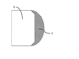
ガラス板6の端面に転写(塗布)した樹脂は液体の性質により、例えば、端面に沿って図4に示したようなかまぼこ状の樹脂(硬化後)7になる。ほぼ均一に塗布が行われることにより、ガラス板6のどの場所でも、樹脂7は、ほぼ同じ断面形状(断面形状がほぼ同形状)を形成し、安定な厚みで塗布された樹脂付きガラスを得ることができる。ガラス板6の端面に転写(塗布)した樹脂を、適宜、UV、加熱等で硬化させ、樹脂付きガラス板が作製される。ガラス板6のどの端面においても、塗布され、硬化した樹脂7が、ほぼ同じ断面形状であることによって、ガラス板6において、安定な機械特性(曲げ特性)が得られる。なお、前記方法を用いて樹脂を塗布すると、ガラスの端面の形状にもよるが、樹脂の凝集エネルギーによってかまぼこ型の樹脂断面形状が得られる。塗布、硬化した樹脂7がほぼ同じ断面形状であるとは、例えば、かまぼこ型の断面積の差が40%以内であるような形状である状態を示す。
The resin transferred (applied) to the end surface of the
以下、実施例及び比較例に基づいて本発明をより具体的に説明するが、本発明は以下の実施例に制限されるものではない。 EXAMPLES Hereinafter, although this invention is demonstrated more concretely based on an Example and a comparative example, this invention is not restrict | limited to a following example.
[ガラス板]
大判から個片化されたガラスとして松浪硝子工業株式会社製ソーダガラス(60mm×80mm×0.55mm、面取り加工有り)を使用した。
[Glass plate]
A soda glass (60 mm × 80 mm × 0.55 mm, with chamfering) manufactured by Matsunami Glass Industrial Co., Ltd. was used as the glass separated into pieces from a large format.
[樹脂a]
(A)成分としてTE-2000(日本曹達株式会社製、アクリル変性ポリブタジエン樹脂、数平均分子量:約1,000)52質量部、(B)成分として2-ヒドロオキシエチルアクリレート35質量部、ラウリルアクリレート10質量部、(C)成分としてN,N´-テトラエチル-4,4´-ジアミノベンゾフェノン0.2質量部、2-(o-クロロフェニル)-4,5-ジフェニルイミダゾール二量体2.5質量部を60℃で加熱攪拌して光硬化型ポリマー樹脂aを得た。樹脂の粘度は、B型粘度計(東機産業)を用いて、M3ロータ、測定温度25℃、回転数30min―1、3分間回転を行うことで測定した。粘度は1.5Pa・sであった。以降の粘度も同様にして測定した。
[Resin a]
As component (A), TE-2000 (manufactured by Nippon Soda Co., Ltd., acrylic-modified polybutadiene resin, number average molecular weight: about 1,000) 52 parts by mass, as component (B) 35 parts by mass of 2-hydroxyethyl acrylate, lauryl acrylate 10 parts by weight, N, N′-tetraethyl-4,4′-diaminobenzophenone as component (C) 0.2 parts by weight, 2- (o-chlorophenyl) -4,5-diphenylimidazole dimer 2.5 parts by weight The part was heated and stirred at 60 ° C. to obtain a photocurable polymer resin a. The viscosity of the resin was measured using a B-type viscometer (Toki Sangyo) by rotating for 3 minutes with an M3 rotor, a measurement temperature of 25 ° C., a rotation speed of 30 min −1 . The viscosity was 1.5 Pa · s. The subsequent viscosity was measured in the same manner.
[樹脂b]
樹脂aのTE-2000を48質量部、ラウリルアクリレートを14質量部に換えた以外は樹脂aと同様にして樹脂bを得た。粘度(測定条件は樹脂aと同じ)は1Pa・sであった。
[Resin b]
Resin b was obtained in the same manner as Resin a except that TE-2000 of Resin a was changed to 48 parts by mass and Lauryl acrylate was changed to 14 parts by mass. The viscosity (measurement conditions are the same as for resin a) was 1 Pa · s.
[樹脂シート作製]
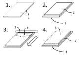
図1に示すように、以上で得た樹脂4について樹脂シート5を作製した。樹脂シート5の下地1として、140mm×180mm×2mmのガラス板を用いた。下地1の上に滑り止め2として無塵紙を両面テープによって設けた。無塵紙を貼り付けた下地1の上に樹脂4を垂らし、バーコーター3を用いて樹脂シート5を作製した。
[Production of resin sheet]
As shown in FIG. 1, the
[実施例1]
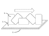
樹脂aを用いて樹脂シート5を作製した。樹脂シート5作製時に使用するバーコーター3の厚みを75μmに設定した。図2に示すように前記ガラス板6の端面と、樹脂シート5とが接触するように樹脂シート5の上を回転させ、ガラス板6の端面全周に樹脂を塗布した。アイグラフィックス株式会社製UV照射装置にて硬化を行った。照射出力は照度計(ウシオ電機株式会社製)にて測定し、照射強度400mW/cm2で総照射量が350mJ/cm2になるように照射して目的の樹脂付きガラス板を得た。
[Example 1]
A
[実施例2]
樹脂bを用いて樹脂シートを作製した。それ以外の条件は実施例1と同様とした。
[Example 2]
A resin sheet was prepared using the resin b. The other conditions were the same as in Example 1.
[実施例3]
樹脂aを用いて樹脂シートを作製した。樹脂シート作製時に使用するバーコーターの厚みを50μmに設定した。それ以外の条件は実施例1と同様とした。
[Example 3]
A resin sheet was prepared using the resin a. The thickness of the bar coater used when preparing the resin sheet was set to 50 μm. The other conditions were the same as in Example 1.
[実施例4]
樹脂bを用いて樹脂シートを作製した。樹脂シート作製時に使用するバーコーターの厚みを50μmに設定した。それ以外の条件は実施例1と同様とした。
[Example 4]
A resin sheet was prepared using the resin b. The thickness of the bar coater used when preparing the resin sheet was set to 50 μm. The other conditions were the same as in Example 1.
[比較例1]
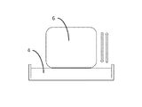
樹脂aについてディップ方式でガラス板6の端面に樹脂4の塗布を行った。図3に示すようにディップ方式は樹脂4の液面にガラス板6の端面が均一に接するように上方から接触させ、ゆっくりと上方に引き上げることで樹脂4の塗布を行った。樹脂4を塗布したガラス板6は実施例1と同様にUV照射装置で硬化し、樹脂付きガラス板を得た。
[Comparative Example 1]
The
[比較例2]
樹脂bについて比較例1と同様にディップ方式での塗布を行い、樹脂付きガラス板を得た。
[Comparative Example 2]
About the resin b, it applied by the dip method similarly to the comparative example 1, and obtained the glass plate with resin.
実施例1〜4および比較例1、2で得られた樹脂付きガラス板について、下記均一塗布性と曲げ特性の評価を行った。
〔均一塗布性〕
実施例1〜4および比較例1、2で得られた樹脂付きガラス板について、光学顕微鏡(OLYMPUS製SZX16)を用いて画像処理による樹脂膜厚み測定を行った。樹脂塗布前のガラス基板について、主面に垂直な方向から写真撮影を行い、樹脂塗布後に同じ場所の撮影を行った。画像より樹脂の塗布された厚みを測定した。
〔曲げ特性〕
実施例1〜4および比較例1、2で得られた樹脂付きガラス板についてオートグラフ(株式会社島津製作所製EZ-TEST)を用いて4点曲げ試験を実施した。下部支点間距離を50mm、ポンチ間距離を25mm、ポンチローラーの半径4mm、ポンチの首振り機構有りの条件で4点曲げ試験を行った。
前記均一塗布性の評価結果を表1に示した。また、前記曲げ強度(曲げ特性)の評価結果を纏めて表2に示した。
For the glass plates with resin obtained in Examples 1 to 4 and Comparative Examples 1 and 2, the following uniform coating properties and bending properties were evaluated.
[Uniform coating properties]
The resin-coated glass plates obtained in Examples 1 to 4 and Comparative Examples 1 and 2 were measured for resin film thickness by image processing using an optical microscope (SZX16 manufactured by OLYMPUS). The glass substrate before resin application was photographed from the direction perpendicular to the main surface, and the same location was photographed after resin application. The thickness of the resin applied was measured from the image.
(Bending properties)
The glass plate with resin obtained in Examples 1 to 4 and Comparative Examples 1 and 2 was subjected to a four-point bending test using an autograph (EZ-TEST manufactured by Shimadzu Corporation). A four-point bending test was performed under the conditions of a distance between the lower fulcrums of 50 mm, a distance between punches of 25 mm, a radius of punch roller of 4 mm, and a punch swing mechanism.
The evaluation results of the uniform coatability are shown in Table 1. The evaluation results of the bending strength (bending characteristics) are summarized in Table 2.

表1に示されるように、実施例1〜4に対し、比較例1〜2では、樹脂膜厚みの平均値の大きさに対するばらつきを示す変動係数CVが高くなっていて、ばらつきが大きいことがわかる。 As shown in Table 1, compared to Examples 1 to 4, in Comparative Examples 1 and 2, the variation coefficient CV indicating the variation with respect to the average value of the resin film thickness is high, and the variation is large. Recognize.
表2に示されるように、比較例1、比較例2では4点曲げ強度の平均値が、転写方式に比べ半分程度の値になる。また、実施例の転写方式に比べ、比較例のディップ方式では平均値の大きさに対するばらつきを示す変動係数CVが大きくなり、試験ごとのばらつきが大きいことがわかる。 As shown in Table 2, in Comparative Examples 1 and 2, the average value of the four-point bending strength is about half that of the transfer method. Further, it can be seen that the variation coefficient CV indicating the variation with respect to the average value is larger in the comparative dip method than in the transfer method in the example, and the variation from test to test is large.
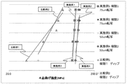
実施例1〜4と比較例1〜2のばらつきの度合いについてワイブルプロットを用いて図5に示した。 About the degree of dispersion | variation of Examples 1-4 and Comparative Examples 1-2, it showed in FIG. 5 using the Weibull plot.
図5のワイブルプロットでは4点曲げ強度の値が高くなるほどプロット点が右側に寄る。またプロットを結んだ近似曲線の傾きが大きくなるほど4点曲げ強度のばらつきが少ないことを示す。図5に示されるように、実施例1〜4の転写方式ではプロットが右寄りにあり、プロットの傾きも大きくなっている。このことから実施例1〜4の方法では4点曲げ強度のばらつきが小さいことがわかる。一方で比較例1〜2のディップ方式ではプロットの点が実施例1〜4のものに比べて左寄りにあり、プロットの傾きが小さくなっていることがわかる。このことから比較例1〜2の方法では4点曲げ強度のばらつきが大きくなることがわかる。 In the Weibull plot of FIG. 5, the plot point is shifted to the right side as the value of the 4-point bending strength increases. Also, the larger the slope of the approximate curve connecting the plots, the smaller the variation in the 4-point bending strength. As shown in FIG. 5, in the transfer methods of Examples 1 to 4, the plot is on the right side, and the slope of the plot is also large. From this, it can be seen that the variations of the 4-point bending strength are small in the methods of Examples 1 to 4. On the other hand, in the dip method of Comparative Examples 1 and 2, the plot point is on the left side compared to Examples 1 to 4, and it can be seen that the slope of the plot is small. From this, it can be seen that the variation of the four-point bending strength is increased in the methods of Comparative Examples 1 and 2.
特定の実施形態を示して説明したが、本発明の趣旨及び範囲から逸脱することなく、様々な変更及び置換がなされ得る。したがって、本発明は例示により説明されており、それらには限定されない。 While particular embodiments have been shown and described, various changes and substitutions can be made without departing from the spirit and scope of the invention. Accordingly, the present invention has been described by way of illustration and not limitation.
1 下地、2 滑り止め、3 バーコーター、4 樹脂(液状)、5 樹脂シート、6 個片化されたガラス板、7 樹脂(硬化後)。 1 base, 2 non-slip, 3 bar coater, 4 resin (liquid), 5 resin sheet, 6 pieces of glass plate, 7 resin (after curing).
Claims (4)
Priority Applications (1)
| Application Number | Priority Date | Filing Date | Title |
|---|---|---|---|
| JP2014041567A JP2015166300A (en) | 2014-03-04 | 2014-03-04 | Manufacturing method of glass plate with resin and glass plate with resin obtained by using the manufacturing method |
Applications Claiming Priority (1)
| Application Number | Priority Date | Filing Date | Title |
|---|---|---|---|
| JP2014041567A JP2015166300A (en) | 2014-03-04 | 2014-03-04 | Manufacturing method of glass plate with resin and glass plate with resin obtained by using the manufacturing method |
Publications (1)
| Publication Number | Publication Date |
|---|---|
| JP2015166300A true JP2015166300A (en) | 2015-09-24 |
Family
ID=54257394
Family Applications (1)
| Application Number | Title | Priority Date | Filing Date |
|---|---|---|---|
| JP2014041567A Pending JP2015166300A (en) | 2014-03-04 | 2014-03-04 | Manufacturing method of glass plate with resin and glass plate with resin obtained by using the manufacturing method |
Country Status (1)
| Country | Link |
|---|---|
| JP (1) | JP2015166300A (en) |
Citations (5)
| Publication number | Priority date | Publication date | Assignee | Title |
|---|---|---|---|---|
| JPS5712859A (en) * | 1980-06-26 | 1982-01-22 | Japan Crown Cork Co Ltd | Working method for article |
| JPH1095636A (en) * | 1996-09-17 | 1998-04-14 | Nippon Sheet Glass Co Ltd | Impact resistant glass |
| JP2007230849A (en) * | 2006-03-03 | 2007-09-13 | Nippon Sheet Glass Co Ltd | Glass plate end coating method, glass plate end coating apparatus, and glass plate end coated by the glass plate end coating method |
| JP2012527399A (en) * | 2009-05-21 | 2012-11-08 | コーニング インコーポレイテッド | Thin substrate with mechanical durability edge |
| WO2014085174A1 (en) * | 2012-11-28 | 2014-06-05 | Corning Incorporated | Method and system for coating glass edges |
-
2014
- 2014-03-04 JP JP2014041567A patent/JP2015166300A/en active Pending
Patent Citations (5)
| Publication number | Priority date | Publication date | Assignee | Title |
|---|---|---|---|---|
| JPS5712859A (en) * | 1980-06-26 | 1982-01-22 | Japan Crown Cork Co Ltd | Working method for article |
| JPH1095636A (en) * | 1996-09-17 | 1998-04-14 | Nippon Sheet Glass Co Ltd | Impact resistant glass |
| JP2007230849A (en) * | 2006-03-03 | 2007-09-13 | Nippon Sheet Glass Co Ltd | Glass plate end coating method, glass plate end coating apparatus, and glass plate end coated by the glass plate end coating method |
| JP2012527399A (en) * | 2009-05-21 | 2012-11-08 | コーニング インコーポレイテッド | Thin substrate with mechanical durability edge |
| WO2014085174A1 (en) * | 2012-11-28 | 2014-06-05 | Corning Incorporated | Method and system for coating glass edges |
Similar Documents
| Publication | Publication Date | Title |
|---|---|---|
| US20170320261A1 (en) | Method for Producing Patterned Materials | |
| JP5834786B2 (en) | Measurement method of thermal expansion coefficient. | |
| TWI461504B (en) | Adhesive sheet for mold fixing, adhesive tape for mold fixing, and manufacturing method of fine structure | |
| TWI675737B (en) | Method for manufacturing polarizing plate, polarizing plate, optical film and image display device | |
| JP2014149520A5 (en) | ||
| JP6185088B2 (en) | Method for producing laminated film | |
| TW201410334A (en) | Roll coating process and apparatus | |
| JP2020090090A (en) | Mold-release film having ultra low release force and manufacturing method therefor | |
| KR20160038745A (en) | Silicon based coating composition and silicon based release film | |
| JP2016113506A (en) | Silicone rubber film as stress relaxation layer and flexible device having the same | |
| US20150047883A1 (en) | Transparent conductive coatings on an elastomeric substrate | |
| TW201631093A (en) | UV-curable polymer, and UV-curable hot-melt adhesive containing same | |
| CN104108174B (en) | Process the processing technology and its emebosser of the polyolefin antiadhesion barrier of corrugated | |
| JP2015166300A (en) | Manufacturing method of glass plate with resin and glass plate with resin obtained by using the manufacturing method | |
| JP6442602B2 (en) | Optical sheet containing nanopattern and method for producing the same | |
| US9623644B2 (en) | Profiled coatings for enabling vacuumless lamination of stencil printed liquid optically clear adhesives | |
| JP2014048324A (en) | Hard coat film manufacturing method | |
| KR102183226B1 (en) | Manufacturing method of uv paint coating layer on film | |
| JP2014210362A (en) | Blanket for offset printing, and method for producing the blanket | |
| JP6771746B2 (en) | Laminate | |
| US20250231478A1 (en) | Method and device for producing micro- and/or nanostructures | |
| JP2012081619A (en) | Method of manufacturing member having unevenly patterned surface | |
| CN103963283A (en) | Forming roller, and manufacturing equipment and manufacturing method thereof | |
| JP2017202653A (en) | Laminate | |
| JP2009202442A (en) | Release sheet and its manufacturing process |
Legal Events
| Date | Code | Title | Description |
|---|---|---|---|
| A621 | Written request for application examination |
Free format text: JAPANESE INTERMEDIATE CODE: A621 Effective date: 20170228 |
|
| A977 | Report on retrieval |
Free format text: JAPANESE INTERMEDIATE CODE: A971007 Effective date: 20170817 |
|
| A131 | Notification of reasons for refusal |
Free format text: JAPANESE INTERMEDIATE CODE: A131 Effective date: 20170824 |
|
| A02 | Decision of refusal |
Free format text: JAPANESE INTERMEDIATE CODE: A02 Effective date: 20180322 |