JP2015161970A - Electronic terminal equipment, pen device, electronic terminal system, and information transmission method - Google Patents
Electronic terminal equipment, pen device, electronic terminal system, and information transmission method Download PDFInfo
- Publication number
- JP2015161970A JP2015161970A JP2014035039A JP2014035039A JP2015161970A JP 2015161970 A JP2015161970 A JP 2015161970A JP 2014035039 A JP2014035039 A JP 2014035039A JP 2014035039 A JP2014035039 A JP 2014035039A JP 2015161970 A JP2015161970 A JP 2015161970A
- Authority
- JP
- Japan
- Prior art keywords
- pen device
- amplitude
- frequency
- electronic terminal
- change
- Prior art date
- Legal status (The legal status is an assumption and is not a legal conclusion. Google has not performed a legal analysis and makes no representation as to the accuracy of the status listed.)
- Granted
Links
Images


Landscapes
- Position Input By Displaying (AREA)
Abstract
Description
本発明は、ペンタブレットやタブレット端末等の電子端末装置、及び、そのような電子端末装置に情報を入力するために用いられる電子ペン等のペン装置に関する。また、本発明は、電子端末装置とペン装置とによって構成される電子端末システム、及び、電子端末装置とペン装置との間において用いられる情報伝達方法等に関する。 The present invention relates to an electronic terminal device such as a pen tablet or a tablet terminal, and a pen device such as an electronic pen used for inputting information to such an electronic terminal device. The present invention also relates to an electronic terminal system including an electronic terminal device and a pen device, and an information transmission method used between the electronic terminal device and the pen device.
従来より、電子ペン等のペン装置を用いてコンピューターに位置情報を入力するためのポインティングデバイスとして、ペンタブレットが用いられている。また、近年においては、パーソナルコンピューターの機能を有するタブレット形状の携帯情報端末(タブレット端末)が普及しており、タブレット端末の入力装置としてタッチパネルが広く採用されている。 Conventionally, a pen tablet has been used as a pointing device for inputting position information to a computer using a pen apparatus such as an electronic pen. In recent years, tablet-shaped portable information terminals (tablet terminals) having the functions of personal computers have become widespread, and touch panels have been widely adopted as input devices for tablet terminals.
ユーザーは、タブレット端末のタッチパネルに表示されるユーザーインターフェース画面を指でタッチすることにより、所望の操作を行うことができる。また、ユーザーは、電子ペン等のペン装置を用いて、タブレット端末のタッチパネルに手書き文字等を入力することができる。ペン装置を用いることにより、手書き文字等の入力を容易にしたり、文字認識の精度を向上させることが可能となる。 The user can perform a desired operation by touching a user interface screen displayed on the touch panel of the tablet terminal with a finger. In addition, the user can input handwritten characters and the like on the touch panel of the tablet terminal using a pen device such as an electronic pen. By using the pen device, it is possible to facilitate input of handwritten characters and improve the accuracy of character recognition.
ペン装置の位置情報をペンタブレットやタブレット端末等の電子端末装置に伝達するためには、電磁波や赤外線等が用いられる。従って、ペン装置は、電磁波や赤外線等を発生する回路に電力を供給するための電池を内蔵している。ペン装置において電池の残量が低下すると、電子端末装置に情報を正確に入力することができなくなるので、ペン装置における電池の残量低下をユーザーに通知することが望まれる。しかしながら、電池の残量低下を表示する表示部や電池の残量低下を音声で知らせる発音部をペン装置に設けると、ペン装置が大型化したり、紛失し易く消耗品として扱われるペン装置のコストが上昇してしまう。 In order to transmit the position information of the pen device to an electronic terminal device such as a pen tablet or a tablet terminal, electromagnetic waves, infrared rays, or the like is used. Therefore, the pen device incorporates a battery for supplying power to a circuit that generates electromagnetic waves, infrared rays, and the like. If the remaining battery level in the pen device decreases, it becomes impossible to accurately input information to the electronic terminal device, so it is desirable to notify the user of a decrease in the remaining battery level in the pen device. However, if a pen unit is provided with a display unit that displays a low battery level and a sound generation unit that informs the low battery level by voice, the cost of the pen unit is likely to be large or lost and handled as a consumable item. Will rise.
関連する技術として、特許文献1には、電子黒板装置において使用される専用ペン等の副装置から電池残量を案内する機能を省略可能な電池残量案内システムが開示されている。この電池残量案内システムは、主装置と、電池から供給される電力を消費しつつ主装置と分離されて使用される副装置とを備え、副装置には、電池が供給できる電力の残量を検出する電池残量検出手段と、電池残量検出手段が検出した電池残量の情報を非接触状態で送信可能な情報送信手段とが設けられ、主装置には、副装置から送信された電池残量の情報を受信する受信手段と、受信手段の受信結果に基づいて電池残量を使用者に案内する案内手段とが設けられている。 As a related technique, Patent Document 1 discloses a battery remaining amount guidance system that can omit a function of guiding a remaining battery amount from a secondary device such as a dedicated pen used in an electronic blackboard device. The battery remaining amount guidance system includes a main device and a sub device that is used separately from the main device while consuming electric power supplied from the battery, and the sub device includes a remaining amount of power that can be supplied by the battery. The battery remaining amount detecting means for detecting the information and the information transmitting means capable of transmitting the battery remaining amount information detected by the battery remaining amount detecting means in a non-contact state are provided. Receiving means for receiving information on the remaining battery level and guidance means for guiding the remaining battery level to the user based on the reception result of the receiving means are provided.
特許文献1によれば、赤外線及び可視光が副装置から出力され、赤外線に含まれる電池残量の情報に基づいて、主装置を通じて電池残量が案内される。このため、電池の電力を消費する副装置側で電池残量を案内する必要がない。従って、副装置から電池残量を案内する機能を省略可能である。これにより、使用による消耗、或いは、分離されて使用されることによる紛失等の可能性が高い副装置の製造コストの抑制を図ることができる。 According to Patent Document 1, infrared light and visible light are output from the secondary device, and the remaining battery level is guided through the main device based on the remaining battery level information included in the infrared ray. For this reason, it is not necessary to guide the remaining battery level on the side of the secondary device that consumes battery power. Therefore, the function of guiding the remaining battery level from the sub device can be omitted. As a result, it is possible to reduce the manufacturing cost of the secondary device that is highly likely to be consumed due to use or lost due to being used separately.
また、特許文献2には、患者等の検出装置において、常に患者等が集まる場所に電池切れ検出専用受信機を設置することにより、何時でも携帯送信機の電池容量が減少したことを管理できるシステムが開示されている。患者等が携帯する携帯送信機は、電池から電源供給されて動作し、2つの異なる信号の内の患者等検出信号又は電池切れ信号を送信する。患者等検出受信機は、患者等が近付くことが危険な場所に設置され、電池切れ受信機は、食堂や集合場所など患者等がよく集まる場所に設置される。携帯送信機から発せられた信号は、患者等検出受信機又は電池切れ受信機で受信・検出され、警報器へと伝えられ、該当する警報をする。 Patent Document 2 discloses a system that can manage that the battery capacity of a portable transmitter is reduced at any time by installing a dedicated battery detection detection receiver at a place where patients and the like always gather in a detection apparatus such as a patient. Is disclosed. A portable transmitter carried by a patient or the like operates with power supplied from a battery and transmits a patient detection signal or a battery dead signal out of two different signals. The patient detection receiver is installed in a place where it is dangerous for the patient or the like to approach, and the battery dead receiver is installed in a place where patients etc. often gather such as a cafeteria or a meeting place. A signal emitted from the portable transmitter is received and detected by a patient detection receiver or a battery dead receiver, and is transmitted to an alarm device to give an appropriate alarm.
特許文献2によれば、食堂や集合場所などにおいて電池切れを速やかに検出し、危険箇所において電池切れにより携帯送信機が非作動となることを防止し、患者等の安全を確保することができる。 According to Patent Document 2, it is possible to quickly detect battery exhaustion at a cafeteria or gathering place, prevent the portable transmitter from being deactivated due to battery exhaustion at a dangerous location, and ensure the safety of patients and the like. .
しかしながら、電子端末装置に位置情報を入力するために用いられるペン装置において、ペン装置の位置情報を送信する送信手段とは別個に電池残量等の情報を送信する送信手段を設けると、ペン装置が大型化すると共に、電子端末装置においても複数の受信手段を設ける必要がある。また、ペン装置から2つの異なる信号を送信する場合には、送信方式が複雑になってしまう。 However, in the pen device used for inputting the position information to the electronic terminal device, if a transmission unit that transmits information such as the remaining battery level is provided separately from the transmission unit that transmits the position information of the pen device, the pen device As the size of the electronic terminal increases, it is necessary to provide a plurality of receiving means also in the electronic terminal device. Further, when two different signals are transmitted from the pen device, the transmission method becomes complicated.
そこで、本発明の目的の1つは、電子端末装置に位置情報を入力するために用いられるペン装置に表示部や追加の送信手段を設けることなく、簡単な送信方式を用いて、ペン装置において発生した電池の残量低下等のイベントをユーザーに通知したり、又は、ペン装置の位置の表示方式を変更したりすることである。 Therefore, one of the objects of the present invention is to use a simple transmission method in a pen device without providing a display unit or additional transmission means in the pen device used for inputting position information to the electronic terminal device. This is to notify the user of an event such as a decrease in the remaining battery level or to change the display method of the position of the pen device.
以上の課題を解決するため、本発明の1つの観点に係る電子端末装置は、電磁誘導方式のペン装置と共に用いられる電子端末装置であって、ペン装置から送信される電磁波を受信して受信信号を生成する受信部と、受信信号の振幅又は周波数を検出する検出部と、受信信号の振幅に基づいて、電子端末装置に対するペン装置の相対的な位置を測定する位置測定部と、一定時間当りの受信信号の振幅又は周波数の変化率が所定の値よりも大きいか否かを判定する判定部と、一定時間当りの受信信号の振幅又は周波数の変化率が所定の値よりも大きいと判定された場合に、ペン装置において発生したイベントを通知し、又は、ペン装置において発生したイベントに従ってペン装置の位置の表示方式を変更する通知部とを備える。 In order to solve the above problems, an electronic terminal device according to one aspect of the present invention is an electronic terminal device used together with an electromagnetic induction pen device, and receives an electromagnetic wave transmitted from the pen device and receives a received signal. A detection unit that detects the amplitude or frequency of the received signal, a position measurement unit that measures the position of the pen device relative to the electronic terminal device based on the amplitude of the received signal, and a fixed time A determination unit that determines whether the rate of change in the amplitude or frequency of the received signal is greater than a predetermined value, and a rate of change in the amplitude or frequency of the received signal per predetermined time is determined to be greater than the predetermined value. A notification unit that notifies an event that has occurred in the pen device or changes the display method of the position of the pen device in accordance with the event that has occurred in the pen device.
本発明の1つの観点に係る電子端末装置によれば、一定時間当りの受信信号の振幅又は周波数の変化率が所定の値よりも大きいか否かを判定し、判定結果に基づいてメッセージの表示等を行うことにより、ペン装置に表示部や追加の送信手段を設けることなく、簡単な送信方式を用いて、ペン装置において発生した電池の残量低下等のイベントをユーザーに通知したり、又は、ペン装置の位置の表示方式を変更したりすることができる。 According to the electronic terminal device of one aspect of the present invention, it is determined whether or not the rate of change in the amplitude or frequency of the received signal per certain time is greater than a predetermined value, and a message is displayed based on the determination result. By using a simple transmission method without providing a display unit or additional transmission means on the pen device, the user is notified of an event such as a low battery level generated in the pen device, or The display method of the position of the pen device can be changed.
ここで、所定の値が、ペン装置の人為的な操作による一定時間当りの受信信号の振幅又は周波数の変化率よりも大きいことが望ましい。その場合には、受信信号の振幅変化又は周波数変化が、ペン装置の人為的な操作によるものであるのか、あるいは、ペン装置における送信信号の振幅変調又は周波数変調によるものであるのかを区別することができる。 Here, it is desirable that the predetermined value is larger than the rate of change in the amplitude or frequency of the received signal per fixed time due to an artificial operation of the pen device. In that case, distinguish whether the amplitude change or frequency change of the received signal is due to an artificial operation of the pen device or due to the amplitude modulation or frequency modulation of the transmission signal in the pen device. Can do.
また、ペン装置の先端部が電子端末装置のタッチパネルに接触しているときに、判定部が、一定時間当りの受信信号の振幅又は周波数の変化率が所定の値よりも大きいか否かを判定するようにしても良い。その場合には、受信部から出力される受信信号の振幅が大きくなるので、判定部は、一定時間当りの受信信号の振幅又は周波数の変化率が所定の値よりも大きいか否かを容易に判定することができる。 In addition, when the tip of the pen device is in contact with the touch panel of the electronic terminal device, the determination unit determines whether the change rate of the amplitude or frequency of the received signal per certain time is greater than a predetermined value. You may make it do. In that case, since the amplitude of the reception signal output from the reception unit increases, the determination unit can easily determine whether the amplitude or frequency change rate of the reception signal per certain time is greater than a predetermined value. Can be determined.
さらに、判定部が、受信信号の振幅又は周波数の変化率のパターンが所定のパターンに一致するか否かを判定するようにしても良い。その場合には、判定部における誤判定の確率が低減される。 Furthermore, the determination unit may determine whether the pattern of the rate of change in the amplitude or frequency of the received signal matches a predetermined pattern. In that case, the probability of erroneous determination in the determination unit is reduced.
以上において、ペン装置が、電池から電力が供給されて動作するペン装置であって、通知部が、一定時間当りの受信信号の振幅又は周波数の変化率が所定の値よりも大きいと判定された場合に、ペン装置における電池の残量低下を通知するようにしても良い。その場合には、ペン装置が電池の残量低下によって使用できなくなる前に、電池の交換又は充電を行うことができる。 In the above, the pen device is a pen device that operates with power supplied from the battery, and the notification unit determines that the rate of change in the amplitude or frequency of the received signal per certain time is greater than a predetermined value. In such a case, a notification of a decrease in the remaining battery level in the pen device may be made. In that case, the battery can be replaced or charged before the pen device becomes unusable due to a low battery level.
本発明の1つの観点に係るペン装置は、電子端末装置に対する相対的な位置の情報を電磁誘導方式によって電子端末装置に伝達するペン装置であって、送信信号を生成し、ペン装置において所定の期間内にイベントが発生した場合に、一定時間当りの振幅又は周波数の変化率が所定の値よりも大きくなる振幅変調又は周波数変調を送信信号に施す変調部と、送信信号に基づいて電磁波を送信する送信部とを備える。 A pen device according to one aspect of the present invention is a pen device that transmits information on a position relative to an electronic terminal device to the electronic terminal device by an electromagnetic induction method. The pen device generates a transmission signal, and the pen device performs predetermined processing. When an event occurs within a period, a modulation unit that applies amplitude modulation or frequency modulation to the transmission signal so that the rate of change in amplitude or frequency per predetermined time is greater than a predetermined value, and transmits electromagnetic waves based on the transmission signal A transmission unit.
本発明の1つの観点に係るペン装置によれば、ペン装置において所定の期間内にイベントが発生した場合に、一定時間当りの振幅又は周波数の変化率が所定の値よりも大きくなる振幅変調又は周波数変調を送信信号に施すことにより、ペン装置に表示部や追加の送信手段を設けることなく、簡単な送信方式を用いて、ペン装置において発生した電池の残量低下やユーザーによるペン装置の操作等のイベントを電子端末装置に伝達することができる。 According to the pen device according to one aspect of the present invention, when an event occurs in a predetermined period in the pen device, the amplitude modulation or the rate of change of the frequency per certain time becomes larger than a predetermined value or By applying frequency modulation to the transmission signal, the battery level of the pen device is reduced and the user operates the pen device using a simple transmission method without providing a display unit or additional transmission means on the pen device. And the like can be transmitted to the electronic terminal device.
ここで、ペン装置が、ペン装置の先端部が物体に接触しているか否かを検出するスイッチをさらに備え、変調部が、ペン装置の先端部が物体に接触している期間内の所定のタイミングで、一定時間当りの振幅又は周波数の変化率が所定の値よりも大きくなる振幅変調又は周波数変調を送信信号に施すようにしても良い。その場合には、ペン装置の先端部が電子端末装置のタッチパネルに接触しているときに変調部が変調動作を行うことができるので、電子端末装置において受信信号の変調を検出することが容易となる。 Here, the pen device further includes a switch for detecting whether or not the tip of the pen device is in contact with the object, and the modulation unit is a predetermined unit within a period in which the tip of the pen device is in contact with the object. At the timing, the transmission signal may be subjected to amplitude modulation or frequency modulation in which the rate of change of amplitude or frequency per fixed time is greater than a predetermined value. In that case, since the modulation unit can perform the modulation operation when the tip of the pen device is in contact with the touch panel of the electronic terminal device, it is easy to detect the modulation of the received signal in the electronic terminal device. Become.
また、ペン装置が、ペン装置に電力を供給する電池の残量を検出する電池残量検出部をさらに備え、変調部が、電池残量検出部によって検出される電池の残量が規定値よりも少ない場合に、一定時間当りの振幅又は周波数の変化率が所定の値よりも大きくなる振幅変調又は周波数変調を送信信号に施すようにしても良い。その場合には、ペン装置が電池の残量低下によって使用できなくなる前に、ペン装置における電池の残量低下を電子端末装置に伝達することができる。 Further, the pen device further includes a battery remaining amount detection unit that detects a remaining amount of the battery that supplies power to the pen device, and the modulation unit detects that the remaining amount of the battery detected by the remaining battery amount detection unit is greater than a specified value. In the case where the transmission frequency is lower, amplitude modulation or frequency modulation in which the rate of change in amplitude or frequency per fixed time is larger than a predetermined value may be applied to the transmission signal. In that case, before the pen device becomes unusable due to the low battery level, the low battery level in the pen device can be transmitted to the electronic terminal device.
本発明の1つの観点に係る電子端末システムは、上記いずれかの電子端末装置と、電子端末装置に対する相対的な位置の情報を電磁誘導方式によって電子端末装置に伝達するペン装置であって、送信信号を生成し、ペン装置において所定の期間内にイベントが発生した場合に、一定時間当りの振幅又は周波数の変化率が所定の値よりも大きくなる振幅変調又は周波数変調を送信信号に施す変調部、及び、送信信号に基づいて電磁波を送信する送信部を含むペン装置とを備える。 An electronic terminal system according to one aspect of the present invention is a pen device that transmits information about a position relative to any one of the electronic terminal devices described above to the electronic terminal device using an electromagnetic induction method, A modulation unit that generates a signal and performs amplitude modulation or frequency modulation on the transmission signal such that the rate of change in amplitude or frequency per predetermined time is greater than a predetermined value when an event occurs in the pen apparatus within a predetermined period. And a pen device including a transmission unit that transmits electromagnetic waves based on the transmission signal.
本発明の1つの観点に係る電子端末システムによれば、ペン装置において所定の期間内にイベントが発生した場合に、ペン装置が、一定時間当りの振幅又は周波数の変化率が所定の値よりも大きくなる振幅変調又は周波数変調を送信信号に施し、電子端末装置が、一定時間当りの受信信号の振幅又は周波数の変化率が所定の値よりも大きいか否かを判定し、判定結果に基づいてメッセージの表示等を行うことにより、ペン装置に表示部や追加の送信手段を設けることなく、簡単な送信方式を用いて、ペン装置において発生した電池の残量低下等のイベントをユーザーに通知したり、又は、ペン装置の位置の表示方式を変更したりすることができる。 According to the electronic terminal system of one aspect of the present invention, when an event occurs in the pen device within a predetermined period, the pen device has a rate of change in amplitude or frequency per predetermined time that is lower than a predetermined value. The amplitude modulation or frequency modulation to be increased is applied to the transmission signal, and the electronic terminal apparatus determines whether the amplitude or frequency change rate of the reception signal per certain time is larger than a predetermined value, and based on the determination result By displaying a message, etc., it is possible to notify the user of an event such as a low battery level occurring in the pen device using a simple transmission method without providing a display unit or additional transmission means in the pen device. Or the display method of the position of the pen device can be changed.
本発明の1つの観点に係る情報伝達方法は、電子端末装置に対する相対的な位置の情報を電磁誘導方式によって電子端末装置に伝達するペン装置において、送信信号に基づいて電磁波を送信するステップ(a)と、ペン装置において所定の期間内にイベントが発生した場合に、一定時間当りの振幅又は周波数の変化率が所定の値よりも大きくなる振幅変調又は周波数変調を送信信号に施し、変調された送信信号に基づいて電磁波を送信するステップ(b)と、電子端末装置において、ペン装置から送信される電磁波を受信して受信信号を生成するステップ(c)と、受信信号の振幅又は周波数を検出するステップ(d)と、受信信号の振幅に基づいて、電子端末装置に対するペン装置の相対的な位置を測定するステップ(e)と、一定時間当りの受信信号の振幅又は周波数の変化率が所定の値よりも大きいか否かを判定するステップ(f)と、一定時間当りの受信信号の振幅又は周波数の変化率が所定の値よりも大きいと判定された場合に、ペン装置において発生したイベントを通知し、又は、ペン装置において発生したイベントに従ってペン装置の位置の表示方式を変更するステップ(g)とを備える。 An information transmission method according to one aspect of the present invention includes a step of transmitting an electromagnetic wave based on a transmission signal in a pen device that transmits information on a relative position to an electronic terminal device to the electronic terminal device by an electromagnetic induction method (a ), When an event occurs within a predetermined period in the pen device, the transmission signal is subjected to amplitude modulation or frequency modulation in which the rate of change in amplitude or frequency per fixed time is greater than a predetermined value. A step (b) of transmitting an electromagnetic wave based on the transmission signal, a step (c) of generating an reception signal by receiving the electromagnetic wave transmitted from the pen device in the electronic terminal device, and detecting an amplitude or a frequency of the reception signal Step (d), measuring the relative position of the pen device with respect to the electronic terminal device based on the amplitude of the received signal, Step (f) for determining whether the rate of change in the amplitude or frequency of the received signal is greater than a predetermined value, and if the rate of change in the amplitude or frequency of the received signal per predetermined time is greater than the predetermined value A step (g) of notifying an event that has occurred in the pen device when the determination is made, or changing the display method of the position of the pen device in accordance with the event that has occurred in the pen device.
本発明の1つの観点に係る情報伝達方法によれば、ペン装置において所定の期間内にイベントが発生した場合に、ペン装置において、一定時間当りの振幅又は周波数の変化率が所定の値よりも大きくなる振幅変調又は周波数変調を送信信号に施し、電子端末装置において、一定時間当りの受信信号の振幅又は周波数の変化率が所定の値よりも大きいか否かを判定し、判定結果に基づいてメッセージの表示等を行うことにより、ペン装置に表示部や追加の送信手段を設けることなく、簡単な送信方式を用いて、ペン装置において発生した電池の残量低下等のイベントをユーザーに通知したり、又は、ペン装置の位置の表示方式を変更したりすることができる。 According to the information transmission method according to one aspect of the present invention, when an event occurs in the pen device within a predetermined period, the change rate of the amplitude or frequency per certain time is less than the predetermined value in the pen device. The amplitude modulation or frequency modulation to be increased is applied to the transmission signal, and in the electronic terminal device, it is determined whether the rate of change in the amplitude or frequency of the reception signal per certain time is greater than a predetermined value, and based on the determination result By displaying a message, etc., it is possible to notify the user of an event such as a low battery level occurring in the pen device using a simple transmission method without providing a display unit or additional transmission means in the pen device. Or the display method of the position of the pen device can be changed.
以下、本発明の実施形態について、図面を参照しながら詳細に説明する。なお、同一の構成要素には同一の参照符号を付して、重複する説明を省略する。
図1は、本発明の各実施形態に係る電子端末装置とペン装置とによって構成される電子端末システムの外観を示す斜視図である。以下の実施形態においては、一例として、電子端末装置としてのタブレット端末と、タブレット端末に位置情報を入力するために用いられるペン装置とによって構成される電子端末システムに本発明を適用した場合について説明する。
Hereinafter, embodiments of the present invention will be described in detail with reference to the drawings. In addition, the same referential mark is attached | subjected to the same component and the overlapping description is abbreviate | omitted.
FIG. 1 is a perspective view showing an external appearance of an electronic terminal system including an electronic terminal device and a pen device according to each embodiment of the present invention. In the following embodiments, as an example, a case where the present invention is applied to an electronic terminal system including a tablet terminal as an electronic terminal device and a pen device used to input position information to the tablet terminal will be described. To do.
図1に示すように、タブレット端末10は、タッチパネル11と、電源スイッチ12と、決定ボタン13と、発音部14とを含んでも良い。ユーザーが電源スイッチ12を押下することにより、タブレット端末10が動作を開始する。ユーザーは、タッチパネル11に表示されるユーザーインターフェース画面を指でタッチすることにより、所望の操作を行うことができる。決定ボタン13は、タッチパネル11に表示された事項を決定する際等に押下される。発音部14は、スピーカーを含んでおり、メッセージ等の音声を発生する。本実施形態においては、タブレット端末10が、電磁誘導方式のペン装置20と共に用いられる。
As illustrated in FIG. 1, the
ペン装置20は、電源スイッチ21と、操作スイッチ22と、マイクロスイッチ23とを含んでも良い。ユーザーが電源スイッチ21を押下することにより、ペン装置20が動作を開始する。ペン装置20は、タブレット端末10に対する相対的な位置の情報を電磁誘導方式によってタブレット端末10に伝達する。従って、ユーザーは、ペン装置20を用いて、タブレット端末10のタッチパネル11に手書き文字等を入力することができる。ペン装置20を用いることにより、手書き文字等の入力を容易にしたり、文字認識の精度を向上させることが可能となる。
The
操作スイッチ22は、タブレット端末10のタッチパネル11に表示されるペン装置20の位置の表示方式を変更するために用いられる。具体的には、操作スイッチ22は、ユーザーがペン装置20を用いて手書き文字等を入力する際に、タッチパネル11に表示される点や線の色を変更するために用いられても良い。例えば、タブレット端末10の電源スイッチ12投入時には、デフォルトとして黒色が設定されており、ユーザーが操作スイッチ22を押下する度に、タッチパネル11に表示される点や線の色が、赤色、青色、緑色等に順次変更される。
The
あるいは、操作スイッチ22は、ユーザーがペン装置20を用いて手書き文字等を入力する際に、タッチパネル11に表示される点や線の太さを変更するために用いられても良い。例えば、タブレット端末10の電源スイッチ12投入時には、デフォルトとして細字が設定されており、ユーザーが操作スイッチ22を押下する度に、タッチパネル11に表示される点や線の太さが、次第に太字となるように順次変更される。
Alternatively, the
あるいは、操作スイッチ22は、ユーザーがペン装置20を用いてタッチパネル11に点や線を描写する描写モードと、ユーザーがペン装置20を用いてタッチパネル11から点や線を消去する消去モードとを切り換えるために用いられても良い。例えば、タブレット端末10の電源スイッチ12投入時には、デフォルトとして描写モードが設定されており、ユーザーが操作スイッチ22を押下する度に、描写モードが消去モードに変更され、さらに、消去モードが描写モードに変更される。
Alternatively, the
マイクロスイッチ23は、ペン装置20の先端部に設けられており、ペン装置20の先端部が物体に接触すると変位して内部回路の電気接続を変更する。これにより、マイクロスイッチ23は、ペン装置20の先端部が物体に接触しているか否かを検出することができる。
The
また、マイクロスイッチ23として多段スイッチを設けても良い。例えば、ペン装置20の先端部がタブレット端末10のタッチパネル11に強く接触してマイクロスイッチ23が2段階に変位すると、タッチパネル11に表示される点や線の太さが細字から太字に変更される。
Further, a multistage switch may be provided as the
図2は、本発明の第1の実施形態に係るペン装置の構成例を示すブロック図である。ペン装置20は、電池210と、電池残量検出部220と、制御部230と、変調部240と、送信部250とを含んでいる。
FIG. 2 is a block diagram illustrating a configuration example of the pen device according to the first embodiment of the present invention. The
電池210は、通常のボタン電池でも良いし、充電可能な充電池でも良く、ペン装置20の各部に電力を供給する。電池210として充電池が用いられる場合には、充電池を充電するための充電回路が、ペン装置20の内部に設けられても良い。電池残量検出部220は、電池210の残量を検出し、検出信号を制御部230に出力する。
The
制御部230は、図1に示す電源スイッチ21、操作スイッチ22、及び、マイクロスイッチ23と、制御回路231とを含んでいる。制御回路231は、電池残量検出部220から出力される検出信号に基づいて、電池残量検出部220によって検出される電池210の残量が規定値よりも少ないか否かを判定する。例えば、制御回路231は、電池210の初期電圧が3.6Vである場合に、ペン装置20の使用に伴って電池210の電圧が1.8V未満となったときに、電池210の残量が低下したと判定する。
The
変調部240は、振幅変調回路241と、発振駆動回路242と、並列接続されたコイルL1及びキャパシターC1によって構成される共振回路とを含んでいる。発振駆動回路242は、共振回路を駆動して共振周波数において発振動作を行うことにより、送信信号を生成する。
The
制御回路231は、ペン装置20において所定の期間内にイベントが発生した場合に、所定の変調動作を行うように振幅変調回路241を制御する。その際に、振幅変調回路241は、発振駆動回路242において生成される送信信号に対し、一定時間当りの振幅の変化率が所定の値よりも大きくなる振幅変調を施す。ただし、ユーザーがペン装置20を移動させた場合にも受信信号の振幅は変化するので、所定の値は、ペン装置20の人為的な操作による一定時間当りの受信信号の振幅の変化率よりも大きいことが望ましい。これにより、受信信号の振幅変化が、ペン装置20の人為的な操作によるものであるのか、あるいは、ペン装置20における送信信号の振幅変調によるものであるのかを区別することができる。
The
イベントの内容は、タブレット端末10(図1)及びペン装置20において、予め設定されている。例えば、イベントの内容がペン装置20における電池210の残量低下であると設定されている場合に、制御回路231は、電池残量検出部220によって検出される電池210の残量が規定値よりも少ないときに、所定の変調動作を行うように変調部240を制御する。これにより、ペン装置20が電池210の残量低下によって使用できなくなる前に、ペン装置20における電池の残量低下をタブレット端末10に伝達することができる。
The contents of the event are preset in the tablet terminal 10 (FIG. 1) and the
また、イベントの内容がユーザーによる操作スイッチ22の押下であると設定されている場合に、制御回路231は、ユーザーが操作スイッチ22を押下したときに、所定の変調動作を行うように変調部240を制御する。これにより、タブレット端末10のタッチパネル11に表示される点や線の色又は太さを変更したり、あるいは、描写モードと消去モードとを切り換えることができる。
In addition, when the content of the event is set to be a press of the
さらに、イベントの内容がマイクロスイッチ23の2段階変位であると設定されている場合に、制御回路231は、ユーザーがペン装置20の先端部をタブレット端末10のタッチパネル11に強く接触させてマイクロスイッチ23を2段階に変位させたときに、所定の変調動作を行うように変調部240を制御する。これにより、タブレット端末10のタッチパネル11に表示される点や線の太さを変更することができる。
Further, when the content of the event is set to be a two-step displacement of the
送信部250は、送信回路251と、アンテナ252とを含んでいる。送信回路251は、制御回路231の制御の下で、変調部240によって生成された送信信号を電力増幅してアンテナ252に供給する。アンテナ252は、電力増幅された送信信号に基づいて電磁波を送信する。
The
マイクロスイッチ23は、ペン装置20の送信動作のオンとオフとを切り換えるために用いられても良い。その場合には、ペン装置20の先端部がタブレット端末10のタッチパネル11に接触してマイクロスイッチ23が変位すると、制御回路231が、送信信号をアンテナ252に供給するように送信回路251を制御する。これにより、タブレット端末10において、ペン装置20の先端部がタッチパネル11に接触したことを検出することができる。
The
それに加えて、又は、それに替えて、マイクロスイッチ23は、所定の変調動作を行うタイミングを決定するために用いられても良い。その場合には、制御回路231が、ペン装置20の先端部がタブレット端末10のタッチパネル11に接触してマイクロスイッチ23が変位している期間内の所定のタイミングで所定の変調動作を行うように変調部240を制御する。これにより、ペン装置20の先端部がタブレット端末10のタッチパネル11に接触しているときに変調部240が所定の変調動作を行うことができるので、タブレット端末10において受信信号の変調を検出することが容易となる。
In addition, or instead, the
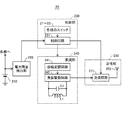
図3は、本発明の第1の実施形態に係るタブレット端末の構成例を示すブロック図である。タブレット端末10は、図1に示すタッチパネル11及び発音部14と、増幅器120と、振幅検出部130と、位置測定部140と、画像信号生成部150と、判定部160と、音声信号生成部170と、制御部180とを含んでいる。
FIG. 3 is a block diagram illustrating a configuration example of the tablet terminal according to the first embodiment of the present invention. The
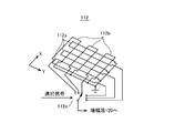
タッチパネル11は、液晶パネル等の表示パネルを含む表示部111と、デジタイザー112とを重畳することによって構成されている。本実施形態においては、図1に示すペン装置20によって指示された位置を検出する方式として電磁誘導方式を採用しており、ペン装置20から送信される電磁波を受信して受信信号を生成する受信部の一例として、デジタイザー112が用いられる。
The
図4は、図3におけるデジタイザーの構成例を示す概略図である。図4には、タッチパネルの表面に平行な面内において互いに直交するX軸及びY軸が示されている。デジタイザー112は、例えば、表示パネルの保護層の裏面に設けられた第1群のループアンテナ112a及び第2群のループアンテナ112bと、それらのループアンテナ112a及び112bの接続を切り換えるセレクター112cとを含んでいる。
FIG. 4 is a schematic diagram showing a configuration example of the digitizer in FIG. FIG. 4 shows an X axis and a Y axis orthogonal to each other in a plane parallel to the surface of the touch panel. The
第1群のループアンテナ112aは、X軸方向に配列されており、各々のループアンテナは、Y軸方向に長手方向を有している。また、第2群のループアンテナ112bは、Y軸方向に配列されており、各々のループアンテナは、X軸方向に長手方向を有している。
The first group of
第1群のループアンテナ112a及び第2群のループアンテナ112bの各々は、ペン装置20から送信される電磁波を受信して受信信号を生成し、受信信号をセレクター112cのそれぞれの入力端子に供給する。セレクター112cは、図3に示す制御部180から出力される選択信号に従って、複数の入力端子にそれぞれ供給された複数の受信信号の内から1つの受信信号を順次選択し、選択された受信信号を増幅器120に出力する。
Each of the first group of
再び図3を参照すると、増幅器120は、デジタイザー112から出力された受信信号を増幅し、増幅された受信信号を振幅検出部130に出力する。振幅検出部130は、増幅器120から出力された受信信号に対して包絡線検波処理を施すことにより、受信信号の振幅を検出する。
Referring to FIG. 3 again, the
位置測定部140は、振幅検出部130によって検出された受信信号の振幅に基づいて、タブレット端末10に対するペン装置20(図1)の相対的な位置を測定する。例えば、位置測定部140は、図4に示す第1群のループアンテナ112aの内で最も大きい振幅を有する受信信号を生成するループアンテナの位置に基づいて、ペン装置20の先端部の位置のX座標を決定しても良い。また、位置測定部140は、図4に示す第2群のループアンテナ112bの内で最も大きい振幅を有する受信信号を生成するループアンテナの位置に基づいて、ペン装置20の先端部の位置のY座標を決定しても良い。
The
あるいは、位置測定部140は、図4に示す第1群のループアンテナ112aによってそれぞれ生成される複数の受信信号の振幅の分布に基づいて、ペン装置20の先端部の位置のX座標を補間により求めても良い。また、位置測定部140は、図4に示す第2群のループアンテナ112bによってそれぞれ生成される複数の受信信号の振幅の分布に基づいて、ペン装置20の先端部の位置のY座標を補間により求めても良い。
Alternatively, the
画像信号生成部150は、描写モードにおいて、位置測定部140によって測定されたペン装置20の先端部の位置に対応する表示部111の位置に点や線が表示される画像データを生成する。これにより、ペン装置20の先端部の位置に対応する表示部111の位置に点や線が描写される。
The image
また、画像信号生成部150は、消去モードにおいて、位置測定部140によって測定されたペン装置20の先端部の位置に対応する表示部111の位置に点や線が表示されない画像データを生成する。これにより、ペン装置20の先端部の位置に対応する表示部111の位置に既に描写されていた点や線が消去される。
Further, the image
判定部160は、デジタイザー112のセレクター112c(図4)が受信信号の選択を変更しない期間において振幅検出部130によって検出された受信信号の振幅に基づいて、一定時間当りの受信信号の振幅の変化率が所定の値よりも大きいか否かを判定する。一定時間当りの受信信号の振幅の変化率が所定の値よりも大きい場合には、ペン装置20において送信信号に所定の振幅変調が施されたことになる。そのときの振幅変化は、タブレット端末10に対するペン装置20の先端部の相対的な位置の変化を表すものではないので、位置測定部140は、そのときの振幅の情報を、ペン装置20の先端部の位置を測定するために使用しない。
Based on the amplitude of the received signal detected by the
ここで、ペン装置20の先端部がタブレット端末10のタッチパネル11に接触しているときに、判定部160が、一定時間当りの受信信号の振幅の変化率が所定の値よりも大きいか否かを判定することが望ましい。そのためには、ペン装置20の先端部がタッチパネル11に接触しているときに、ペン装置20が電磁波を送信すれば良い。これにより、デジタイザー112から出力される受信信号の振幅が大きくなるので、判定部160は、一定時間当りの受信信号の振幅の変化率が所定の値よりも大きいか否かを容易に判定することができる。
Here, when the tip of the
また、判定部160は、所定のパターンを予め格納部に格納しておき、受信信号の振幅の変化率のパターンが所定のパターンに一致するか否かを判定するようにしても良い。これにより、判定部160における誤判定の確率が低減される。例えば、所定のパターンは、受信信号の振幅の増加率又は減少率、振幅変化の期間、又は、複数の振幅変化の間隔等を規定する。なお、これらを規定する数値には、許容範囲が設けられる。
Further, the
画像信号生成部150及び表示部111、又は、音声信号生成部170及び発音部14は、図1に示すペン装置20において発生したイベントを通知する通知部を構成している。判定部160によって、一定時間当りの受信信号の振幅の変化率が所定の値よりも大きいと判定された場合には、通知部が、ペン装置20において発生したイベントを通知し、又は、ペン装置20において発生したイベントに従って、表示部111におけるペン装置20の位置の表示方式を変更する。
The image
例えば、イベントの内容がペン装置20における電池の残量低下であると設定されている場合には、画像信号生成部150が、「電池の残量が低下しました」というメッセージを表示部111に表示したり、又は、音声信号生成部170が、「電池の残量が低下しました」というメッセージを発音部14に発生させる。これにより、ペン装置20が電池の残量低下によって使用できなくなる前に、電池の交換又は充電を行うことができる。
For example, when the content of the event is set to indicate that the battery level of the
また、イベントの内容がユーザーによる操作スイッチ22の押下であると設定されている場合には、画像信号生成部150が、表示部111に表示される点や線の色又は太さを変更したり、あるいは、描写モードと消去モードとを切り換える。さらに、通知部は、ペン装置20の位置の表示方式の変更内容を通知しても良い。例えば、表示部111に表示される点や線の色が黒色から赤色に変更された場合には、画像信号生成部150が、赤色のマーカーを表示部111に表示したり、又は、音声信号生成部170が、「赤色に変更しました」というメッセージを発音部14に発生させる。
In addition, when the event content is set to be a press of the
また、イベントの内容がマイクロスイッチ23の2段階変位であると設定されている場合には、画像信号生成部150が、表示部111に表示される点や線の太さを変更する。さらに、通知部は、ペン装置20の位置の表示方式の変更内容を通知しても良い。例えば、表示部111に表示される点や線の太さが細字から太字に変更された場合には、音声信号生成部170が、「太字」というメッセージを発音部14に発生させる。
When the event content is set as a two-step displacement of the
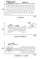
図5は、ペン装置における送信信号及びタブレット端末における受信信号を示す波形図である。図5(A)は、図2に示すペン装置20の発振駆動回路242において生成される送信信号の波形及びその包絡線を示している。起動安定化のための振幅増加期間においては、送信信号の振幅が増加しているが、その後の通常動作時においては、送信信号の振幅が略一定となる。ペン装置20において電池210の残量低下等のイベントが発生した場合には、振幅変調回路241が送信信号に所定の振幅変調を施す。
FIG. 5 is a waveform diagram showing a transmission signal in the pen device and a reception signal in the tablet terminal. FIG. 5A shows a waveform of a transmission signal generated in the
図5(B)は、タブレット端末10とペン装置20との間の距離による受信信号の振幅変化の例を示している。タブレット端末10とペン装置20との間の距離が短い場合には、受信信号の振幅は大きくなり、タブレット端末10とペン装置20との間の距離が長い場合には、受信信号の振幅は小さくなる。図5(B)に示す振幅変化は、ペン装置20の人為的な操作によるものである。
FIG. 5B shows an example of a change in the amplitude of the received signal depending on the distance between the
図5(C)は、図2に示すペン装置20においてイベントが発生した場合における受信信号の振幅変化の例を示している。この例においては、ペン装置20においてイベントが発生した場合に、振幅変調回路241が、送信信号の振幅が小さくなるように送信信号に振幅変調を施している。
FIG. 5C shows an example of a change in the amplitude of the received signal when an event occurs in the
ここで、受信信号の包絡線によって表される振幅Aが変化して振幅(A+ΔA)又は(A−ΔA)となったときの振幅の変化率をΔaとする。振幅の変化率Δaは、次式によって表される。
Δa=ΔA/A≧0
さらに、単位時間Δtにおいて受信信号の振幅が変化率Δaで変化したときに、包絡線変化速度Vを次式によって定義する。
V=Δa/Δt
Here, let Δa be the rate of change in amplitude when the amplitude A represented by the envelope of the received signal changes to become amplitude (A + ΔA) or (A−ΔA). The amplitude change rate Δa is expressed by the following equation.
Δa = ΔA / A ≧ 0
Further, when the amplitude of the received signal changes at the change rate Δa in the unit time Δt, the envelope change speed V is defined by the following equation.
V = Δa / Δt
また、人為的な操作によってペン装置20を移動させたときの最大の包絡線変化速度をVhmaxとする。人為的な操作によるペン装置20の移動速度は、最大で20mm/m秒程度であるので、ペン装置20の移動速度を包絡線変化速度に変換するための係数をαとすると、Vhmaxは次式によって表される。
Vhmax=α×20(mm/m秒)
Further, the maximum envelope change speed when the
Vhmax = α × 20 (mm / msec)
従って、図2に示す振幅変調回路241は、ペン装置20において所定の期間内にイベントが発生した場合に、最大の包絡線変化速度Vmaxが、Vmax>Vhmaxとなるような振幅変調を送信信号に施すことが望ましい。例えば、Vmax=3Vhmaxとしても良い。その場合に、図3に示す判定部160は、受信信号において、最大の包絡線変化速度Vmaxが、4Vhmax>Vmax>2Vhmaxとなるような振幅変化が検出されたときに、ペン装置20においてイベントが発生したと判定しても良い。
Accordingly, the
次に、本発明の第2の実施形態について説明する。
図6は、本発明の第2の実施形態に係るペン装置の構成例を示すブロック図である。第2の実施形態においては、ペン装置20aが、送信信号に対して振幅変調の替りに周波数変調を施す。そのために、ペン装置20aにおいては、図2に示す第1の実施形態に係るペン装置20における変調部240の替りに変調部240aが用いられる。その他の点に関しては、第2の実施形態に係るペン装置20aは、第1の実施形態に係るペン装置20と同様である。
Next, a second embodiment of the present invention will be described.
FIG. 6 is a block diagram illustrating a configuration example of a pen device according to the second embodiment of the present invention. In the second embodiment, the
変調部240aは、周波数変調回路243と、発振駆動回路242と、並列接続されたコイルL1、キャパシターC1及びバリアブルキャパシターC2によって構成される共振回路とを含んでいる。発振駆動回路242は、共振回路を駆動して共振周波数において発振動作を行うことにより、送信信号を生成する。
The
制御回路231は、ペン装置20aにおいて所定の期間内にイベントが発生した場合に、所定の変調動作を行うように周波数変調回路243を制御する。その際に、周波数変調回路243は、バリアブルキャパシターC2の静電容量値を変化させることにより、発振駆動回路242において生成される送信信号に対し、一定時間当りの周波数の変化量が所定の値よりも大きくなる周波数変調を施す。ただし、ユーザーがペン装置20aを移動させた場合にもドップラー効果によって受信信号の周波数は変化するので、所定の値は、ペン装置20aの人為的な操作による一定時間当りの受信信号の周波数の変化率よりも大きいことが望ましい。これにより、受信信号の周波数変化が、ペン装置20aの人為的な操作によるものであるのか、あるいは、ペン装置20aにおける送信信号の周波数変調によるものであるのかを区別することができる。
The
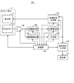
図7は、本発明の第2の実施形態に係るタブレット端末の構成例を示すブロック図である。タブレット端末10aは、受信信号の振幅に加えて受信信号の周波数を検出する。そのために、タブレット端末10aにおいては、図3に示す第1の実施形態に係るタブレット端末10に対して、周波数検出部190が追加されている。周波数検出部190の検出結果は、判定部160に出力される。その他の点に関しては、第2の実施形態に係るタブレット端末10aは、第1の実施形態に係るタブレット端末10と同様である。
FIG. 7 is a block diagram illustrating a configuration example of a tablet terminal according to the second embodiment of the present invention. The
周波数検出部190は、増幅器120から出力された受信信号の周波数を検出する。また、判定部160は、デジタイザー112のセレクター112c(図4)が受信信号の選択を変更しない期間において周波数検出部190によって検出された受信信号の周波数に基づいて、一定時間当りの受信信号の周波数の変化率が所定の値よりも大きいか否かを判定する。一定時間当りの受信信号の周波数の変化率が所定の値よりも大きい場合には、ペン装置20aにおいて送信信号に所定の周波数変調が施されたことになる。
The
ここで、ペン装置20aの先端部がタブレット端末10aのタッチパネル11に接触しているときに、判定部160が、一定時間当りの受信信号の周波数の変化率が所定の値よりも大きいか否かを判定することが望ましい。そのためには、ペン装置20aの先端部がタッチパネル11に接触しているときに、ペン装置20aが電磁波を送信すれば良い。これにより、デジタイザー112から出力される受信信号の振幅が大きくなるので、判定部160は、一定時間当りの受信信号の周波数の変化率が所定の値よりも大きいか否かを容易に判定することができる。
Here, when the tip of the
また、判定部160は、所定のパターンを予め格納部に格納しておき、受信信号の周波数の変化率のパターンが所定のパターンに一致するか否かを判定するようにしても良い。これにより、判定部160における誤判定の確率が低減される。例えば、所定のパターンは、受信信号の周波数の増加率又は減少率、周波数変化の期間、又は、複数の周波数変化の間隔等を規定する。なお、これらを規定する数値には、許容範囲が設けられる。
The
判定部160によって、一定時間当りの受信信号の周波数の変化率が所定の値よりも大きいと判定された場合には、通知部が、図6に示すペン装置20aにおいて発生したイベントを通知し、又は、ペン装置20aにおいて発生したイベントに従って、表示部111におけるペン装置20aの位置の表示方式を変更する。
When the
例えば、イベントの内容がペン装置20aにおける電池の残量低下であると設定されている場合には、画像信号生成部150が、「電池の残量が低下しました」というメッセージを表示部111に表示したり、又は、音声信号生成部170が、「電池の残量が低下しました」というメッセージを発音部14に発生させる。
For example, when the content of the event is set to indicate that the battery level of the
また、イベントの内容がユーザーによる操作スイッチ22の押下であると設定されている場合には、画像信号生成部150が、表示部111に表示される点や線の色又は太さを変更したり、あるいは、描写モードと消去モードとを切り換える。また、イベントの内容がマイクロスイッチ23の2段階変位であると設定されている場合には、画像信号生成部150が、表示部111に表示される点や線の太さを変更する。
In addition, when the event content is set to be a press of the
ここで、受信信号の周波数Fが変化して周波数(F+ΔF)又は(F−ΔF)となったときの周波数の変化率をΔfとする。周波数の変化率Δfは、次式によって表される。
Δf=ΔF/F≧0
さらに、単位時間Δtにおいて受信信号の周波数が変化率Δfで変化したときに、周波数変化速度Uを次式によって定義する。
U=Δf/Δt
Here, the frequency change rate when the frequency F of the received signal changes to become the frequency (F + ΔF) or (F−ΔF) is assumed to be Δf. The frequency change rate Δf is expressed by the following equation.
Δf = ΔF / F ≧ 0
Further, when the frequency of the received signal changes at the change rate Δf in the unit time Δt, the frequency change speed U is defined by the following equation.
U = Δf / Δt
また、人為的な操作によってペン装置20aを移動させたときの最大の周波数変化速度をUhmaxとする。人為的な操作によるペン装置20aの移動速度は、最大で20mm/m秒程度であるので、ペン装置20aの移動速度を周波数変化速度に変換するための係数をβとすると、Uhmaxは次式によって表される。
Uhmax=β×20(mm/m秒)
In addition, the maximum frequency change speed when the
Uhmax = β × 20 (mm / msec)
従って、図6に示す周波数変調回路243は、ペン装置20aにおいて所定の期間内にイベントが発生した場合に、最大の周波数変化速度Umaxが、Umax>Uhmaxとなるような周波数変調を送信信号に施すことが望ましい。例えば、Umax=3Uhmaxとしても良い。その場合に、図7に示す判定部160は、受信信号において、最大の周波数変化速度Umaxが、4Uhmax>Umax>2Uhmaxとなるような周波数変化が検出されたときに、ペン装置20aにおいてイベントが発生したと判定しても良い。
Therefore, the
本発明の第1又は第2の実施形態に係る電子端末装置によれば、一定時間当りの受信信号の振幅又は周波数の変化率が所定の値よりも大きいか否かを判定し、判定結果に基づいてメッセージの表示等を行うことにより、ペン装置に表示部や追加の送信手段を設けることなく、簡単な送信方式を用いて、ペン装置において発生した電池の残量低下等のイベントをユーザーに通知したり、又は、ペン装置の位置の表示方式を変更したりすることができる。 According to the electronic terminal device according to the first or second embodiment of the present invention, it is determined whether or not the rate of change in amplitude or frequency of the received signal per certain time is greater than a predetermined value, and the determination result is By displaying a message on the basis of this, an event such as a low battery level occurring in the pen device can be sent to the user using a simple transmission method without providing a display unit or additional transmission means on the pen device. Notification can be made, or the display method of the position of the pen device can be changed.
次に、本発明の第1又は第2の実施形態に係る電子端末システムによって実施される情報伝達方法について、図1〜図8を参照しながら説明する。図8は、本発明の一実施形態に係る情報伝達方法を示すフローチャートである。 Next, an information transmission method implemented by the electronic terminal system according to the first or second embodiment of the present invention will be described with reference to FIGS. FIG. 8 is a flowchart illustrating an information transmission method according to an embodiment of the present invention.
図8(A)は、ペン装置20又は20aの動作フローを示している。ステップS11において、ユーザーが、ペン装置の電源スイッチ21をオンする。ステップS12において、制御回路231が、発振駆動回路242を起動して送信信号の生成を開始させる。ステップS13において、送信信号の振幅が安定する。ステップS14において、送信部250が、送信信号に基づいて電磁波を送信する。
FIG. 8A shows an operation flow of the
ステップS15において、制御回路231が、ペン装置において所定の期間内にイベントが発生したか否かを判定する。例えば、制御回路231は、電池残量検出部220によって検出される電池210の残量が規定値よりも少ないか否かを判定する。イベントが発生していないと判定された場合には、処理がステップS14に戻る。一方、イベントが発生したと判定された場合には、処理がステップS16に移行する。
In step S15, the
ステップS16において、制御回路231が、一定時間当りの振幅又は周波数の変化率が所定の値よりも大きくなる振幅変調又は周波数変調を送信信号に施すように変調部240又は240aを制御する。送信部250は、変調された送信信号に基づいて電磁波を送信する。その後、処理がステップS14に戻る。
In step S16, the
図8(B)は、タブレット端末10又は10aの動作フローを示している。ステップS21において、ユーザーが、タブレット端末の電源スイッチ12をオンする。ステップS22において、制御部180が、受信部を起動して受信動作を開始させる。ステップS23において、受信部が、ペン装置から送信される電磁波を受信して受信信号を生成する。
FIG. 8B shows an operation flow of the
ステップS24において、振幅検出部130が、受信信号の振幅を検出する。また、周波数検出部190が、受信信号の周波数を検出するようにしても良い。ステップS25において、位置測定部140が、受信信号の振幅に基づいて、タブレット端末に対するペン装置の相対的な位置を測定する。
In step S24, the
ステップS26において、判定部160が、一定時間当りの受信信号の振幅又は周波数の変化率が所定の値よりも大きいか否かを判定する。一定時間当りの変化率が所定の値よりも大きくないと判定された場合には、処理がステップS23に戻る。一方、一定時間当りの変化率が所定の値よりも大きいと判定された場合には、処理がステップS27に移行する。
In step S26, the
ステップS27において、通知部が、ペン装置において発生したイベントを通知し、又は、ペン装置において発生したイベントに従ってペン装置の位置の表示方式を変更する。例えば、イベントの内容がペン装置における電池の残量低下であると設定されている場合には、画像信号生成部150が、「電池の残量が低下しました」というメッセージを表示部111に表示したり、又は、音声信号生成部170が、「電池の残量が低下しました」というメッセージを発音部14に発生させる。
In step S27, the notification unit notifies an event that has occurred in the pen device, or changes the display method of the position of the pen device in accordance with the event that has occurred in the pen device. For example, when the content of the event is set to indicate that the battery level of the pen device is low, the image
また、イベントの内容がユーザーによる操作スイッチ22の押下であると設定されている場合には、画像信号生成部150が、表示部111に表示される点や線の色又は太さを変更したり、あるいは、描写モードと消去モードとを切り換える。また、イベントの内容がマイクロスイッチ23の2段階変位であると設定されている場合には、画像信号生成部150が、表示部111に表示される点や線の太さを変更する。その後、処理がステップS23に戻る。
In addition, when the event content is set to be a press of the
以上の実施形態においては、タブレット端末を用いる電子端末システムに本発明を適用した具体例について説明したが、本発明は、この実施形態に限定されるものではなく、一般的な電子端末システムに適用可能であると共に、当該技術分野において通常の知識を有する者によって、本発明の技術的思想内で多くの変形が可能である。 In the above embodiment, a specific example in which the present invention is applied to an electronic terminal system using a tablet terminal has been described. However, the present invention is not limited to this embodiment, and is applied to a general electronic terminal system. Many modifications are possible within the technical idea of the present invention by those having ordinary knowledge in the art.
10、10a…タブレット端末、11…タッチパネル、12…電源スイッチ、13…決定ボタン、14…発音部、20、20a…ペン装置、21…電源スイッチ、22…操作スイッチ、23…マイクロスイッチ、111…表示部、112…デジタイザー、112a…第1群のループアンテナ、112b…第2群のループアンテナ、112c…セレクター、120…増幅器、130…振幅検出部、140…位置測定部、150…画像信号生成部、160…判定部、170…音声信号生成部、180…制御部、190…周波数検出部、210…電池、220…電池残量検出部、230…制御部、231…制御回路、240、240a…変調部、241…振幅変調回路、242…発振駆動回路、243…周波数変調回路、250…送信部、251…送信回路、252…アンテナ、L1…コイル、C1…キャパシター、C2…バリアブルキャパシター
DESCRIPTION OF
Claims (10)
前記ペン装置から送信される電磁波を受信して受信信号を生成する受信部と、
前記受信信号の振幅又は周波数を検出する検出部と、
前記受信信号の振幅に基づいて、前記電子端末装置に対する前記ペン装置の相対的な位置を測定する位置測定部と、
一定時間当りの前記受信信号の振幅又は周波数の変化率が所定の値よりも大きいか否かを判定する判定部と、
一定時間当りの前記受信信号の振幅又は周波数の変化率が所定の値よりも大きいと判定された場合に、前記ペン装置において発生したイベントを通知し、又は、前記ペン装置において発生したイベントに従って前記ペン装置の位置の表示方式を変更する通知部と、
を備える電子端末装置。 An electronic terminal device used together with an electromagnetic induction pen device,
A receiving unit that receives an electromagnetic wave transmitted from the pen device and generates a reception signal;
A detection unit for detecting the amplitude or frequency of the received signal;
A position measuring unit that measures a relative position of the pen device with respect to the electronic terminal device based on an amplitude of the received signal;
A determination unit for determining whether the rate of change in amplitude or frequency of the received signal per certain time is greater than a predetermined value;
When it is determined that the rate of change in amplitude or frequency of the received signal per certain time is greater than a predetermined value, an event that has occurred in the pen device is notified, or according to the event that has occurred in the pen device A notification unit for changing the display method of the position of the pen device;
An electronic terminal device comprising:
前記通知部が、一定時間当りの前記受信信号の振幅又は周波数の変化率が所定の値よりも大きいと判定された場合に、前記ペン装置における電池の残量低下を通知する、
請求項1〜4のいずれか1項記載の電子端末装置。 The pen device is operated by being supplied with power from a battery,
When the notification unit determines that the rate of change in the amplitude or frequency of the received signal per fixed time is greater than a predetermined value, it notifies a decrease in the remaining battery level in the pen device.
The electronic terminal device of any one of Claims 1-4.
送信信号を生成し、前記ペン装置において所定の期間内にイベントが発生した場合に、一定時間当りの振幅又は周波数の変化率が所定の値よりも大きくなる振幅変調又は周波数変調を前記送信信号に施す変調部と、
前記送信信号に基づいて電磁波を送信する送信部と、
を備えるペン装置。 A pen device that transmits information on a position relative to an electronic terminal device to the electronic terminal device by an electromagnetic induction method,
When a transmission signal is generated and an event occurs within a predetermined period in the pen device, amplitude modulation or frequency modulation in which the rate of change in amplitude or frequency per predetermined time is greater than a predetermined value is applied to the transmission signal. A modulation unit to be applied;
A transmission unit for transmitting electromagnetic waves based on the transmission signal;
Pen device comprising:
前記変調部が、前記ペン装置の先端部が物体に接触している期間内の所定のタイミングで、一定時間当りの振幅又は周波数の変化率が所定の値よりも大きくなる振幅変調又は周波数変調を前記送信信号に施す、
請求項6記載のペン装置。 A switch for detecting whether the tip of the pen device is in contact with an object;
The modulation unit performs amplitude modulation or frequency modulation in which the rate of change in amplitude or frequency per predetermined time is greater than a predetermined value at a predetermined timing within a period in which the tip of the pen device is in contact with an object. Applying to the transmission signal;
The pen device according to claim 6.
前記変調部が、前記電池残量検出部によって検出される電池の残量が規定値よりも少ない場合に、一定時間当りの振幅又は周波数の変化率が所定の値よりも大きくなる振幅変調又は周波数変調を前記送信信号に施す、
請求項6又は7記載のペン装置。 A battery remaining amount detecting unit for detecting a remaining amount of a battery that supplies power to the pen device;
Amplitude modulation or frequency at which the rate of change of amplitude or frequency per predetermined time is greater than a predetermined value when the modulation unit detects that the remaining battery level detected by the remaining battery level detection unit is less than a specified value Modulating the transmitted signal;
The pen device according to claim 6 or 7.
前記電子端末装置に対する相対的な位置の情報を電磁誘導方式によって前記電子端末装置に伝達するペン装置であって、送信信号を生成し、前記ペン装置において所定の期間内にイベントが発生した場合に、一定時間当りの振幅又は周波数の変化率が所定の値よりも大きくなる振幅変調又は周波数変調を前記送信信号に施す変調部、及び、前記送信信号に基づいて電磁波を送信する送信部を含む前記ペン装置と、
を備える電子端末システム。 The electronic terminal device according to any one of claims 1 to 5,
A pen device that transmits information of a relative position with respect to the electronic terminal device to the electronic terminal device by an electromagnetic induction method, when a transmission signal is generated and an event occurs within a predetermined period in the pen device. A modulation unit that performs amplitude modulation or frequency modulation on the transmission signal such that a rate of change in amplitude or frequency per predetermined time is greater than a predetermined value, and a transmission unit that transmits electromagnetic waves based on the transmission signal A pen device;
An electronic terminal system comprising:
前記ペン装置において所定の期間内にイベントが発生した場合に、一定時間当りの振幅又は周波数の変化率が所定の値よりも大きくなる振幅変調又は周波数変調を送信信号に施し、変調された送信信号に基づいて電磁波を送信するステップ(b)と、
前記電子端末装置において、前記ペン装置から送信される電磁波を受信して受信信号を生成するステップ(c)と、
前記受信信号の振幅又は周波数を検出するステップ(d)と、
前記受信信号の振幅に基づいて、前記電子端末装置に対する前記ペン装置の相対的な位置を測定するステップ(e)と、
一定時間当りの前記受信信号の振幅又は周波数の変化率が所定の値よりも大きいか否かを判定するステップ(f)と、
一定時間当りの前記受信信号の振幅又は周波数の変化率が所定の値よりも大きいと判定された場合に、前記ペン装置において発生したイベントを通知し、又は、前記ペン装置において発生したイベントに従って前記ペン装置の位置の表示方式を変更するステップ(g)と、
を備える情報伝達方法。 In the pen device that transmits information of a relative position with respect to the electronic terminal device to the electronic terminal device by an electromagnetic induction method, a step (a) of transmitting an electromagnetic wave based on a transmission signal;
When an event occurs within a predetermined period in the pen device, the transmission signal is subjected to amplitude modulation or frequency modulation in which the rate of change in amplitude or frequency per fixed time is greater than a predetermined value. Transmitting an electromagnetic wave based on (b),
In the electronic terminal device, receiving the electromagnetic wave transmitted from the pen device and generating a received signal (c);
Detecting the amplitude or frequency of the received signal (d);
Measuring the relative position of the pen device with respect to the electronic terminal device based on the amplitude of the received signal (e);
Determining whether the rate of change in amplitude or frequency of the received signal per fixed time is greater than a predetermined value (f);
When it is determined that the rate of change in amplitude or frequency of the received signal per certain time is greater than a predetermined value, an event that has occurred in the pen device is notified, or according to the event that has occurred in the pen device Changing the display method of the position of the pen device (g);
An information transmission method comprising:
Priority Applications (1)
| Application Number | Priority Date | Filing Date | Title |
|---|---|---|---|
| JP2014035039A JP6256097B2 (en) | 2014-02-26 | 2014-02-26 | Electronic terminal device, pen device, electronic terminal system, and information transmission method |
Applications Claiming Priority (1)
| Application Number | Priority Date | Filing Date | Title |
|---|---|---|---|
| JP2014035039A JP6256097B2 (en) | 2014-02-26 | 2014-02-26 | Electronic terminal device, pen device, electronic terminal system, and information transmission method |
Publications (2)
| Publication Number | Publication Date |
|---|---|
| JP2015161970A true JP2015161970A (en) | 2015-09-07 |
| JP6256097B2 JP6256097B2 (en) | 2018-01-10 |
Family
ID=54185051
Family Applications (1)
| Application Number | Title | Priority Date | Filing Date |
|---|---|---|---|
| JP2014035039A Active JP6256097B2 (en) | 2014-02-26 | 2014-02-26 | Electronic terminal device, pen device, electronic terminal system, and information transmission method |
Country Status (1)
| Country | Link |
|---|---|
| JP (1) | JP6256097B2 (en) |
Cited By (1)
| Publication number | Priority date | Publication date | Assignee | Title |
|---|---|---|---|---|
| EP4293487A3 (en) * | 2022-06-15 | 2024-02-28 | Samsung Display Co., Ltd. | Display device and a touch sensing system including the same |
Citations (6)
| Publication number | Priority date | Publication date | Assignee | Title |
|---|---|---|---|---|
| JPH07182090A (en) * | 1993-12-24 | 1995-07-21 | Canon Inc | Information processing equipment |
| JPH07325661A (en) * | 1994-05-30 | 1995-12-12 | Pentel Kk | Coordinate detection device using mutual inductance coupled resonant pen |
| JPH0991077A (en) * | 1995-06-15 | 1997-04-04 | Seiko Denshi Kiki Kk | Wireless coordinate reader and its coordinate indicator |
| JP2007164356A (en) * | 2005-12-12 | 2007-06-28 | Wacom Co Ltd | Position input device and computer system |
| US20070146351A1 (en) * | 2005-12-12 | 2007-06-28 | Yuji Katsurahira | Position input device and computer system |
| JP2011204173A (en) * | 2010-03-26 | 2011-10-13 | Seiko Epson Corp | Handwriting data generating system, handwriting data generating method, and program |
-
2014
- 2014-02-26 JP JP2014035039A patent/JP6256097B2/en active Active
Patent Citations (6)
| Publication number | Priority date | Publication date | Assignee | Title |
|---|---|---|---|---|
| JPH07182090A (en) * | 1993-12-24 | 1995-07-21 | Canon Inc | Information processing equipment |
| JPH07325661A (en) * | 1994-05-30 | 1995-12-12 | Pentel Kk | Coordinate detection device using mutual inductance coupled resonant pen |
| JPH0991077A (en) * | 1995-06-15 | 1997-04-04 | Seiko Denshi Kiki Kk | Wireless coordinate reader and its coordinate indicator |
| JP2007164356A (en) * | 2005-12-12 | 2007-06-28 | Wacom Co Ltd | Position input device and computer system |
| US20070146351A1 (en) * | 2005-12-12 | 2007-06-28 | Yuji Katsurahira | Position input device and computer system |
| JP2011204173A (en) * | 2010-03-26 | 2011-10-13 | Seiko Epson Corp | Handwriting data generating system, handwriting data generating method, and program |
Cited By (2)
| Publication number | Priority date | Publication date | Assignee | Title |
|---|---|---|---|---|
| EP4293487A3 (en) * | 2022-06-15 | 2024-02-28 | Samsung Display Co., Ltd. | Display device and a touch sensing system including the same |
| US12216860B2 (en) | 2022-06-15 | 2025-02-04 | Samsung Display Co., Ltd | Display device and a touch sensing system including the same |
Also Published As
| Publication number | Publication date |
|---|---|
| JP6256097B2 (en) | 2018-01-10 |
Similar Documents
| Publication | Publication Date | Title |
|---|---|---|
| US9513723B2 (en) | Interacting tips for a digitizer stylus | |
| CN102087565B (en) | Stylus applied to touch panel module and method for actively transmitting signal thereof | |
| US9864441B2 (en) | Object orientation detection with a digitizer | |
| US12093472B2 (en) | Stylus and control method therefor, and electronic device | |
| US10073558B2 (en) | Position indicator, position detecting device, and input control method of position detecting device | |
| US10459538B2 (en) | Pressure sensitive stylus | |
| JP2016126503A (en) | Position indicator and signal processing device | |
| EP2972696A1 (en) | Multimode stylus | |
| CN103389804B (en) | Coordinate instruction equipment and the coordinate measurment instrument for measuring its input position | |
| KR20140008637A (en) | Method using pen input device and terminal thereof | |
| US20160041635A1 (en) | Active stylus pen, electronic device and data input system | |
| CN103645813A (en) | Stylus and method for actively transmitting signal thereof | |
| US12277313B2 (en) | Handwriting drawing method and apparatus, electronic device, and readable storage medium | |
| JP6256097B2 (en) | Electronic terminal device, pen device, electronic terminal system, and information transmission method | |
| US20160291956A1 (en) | Active pen reprogramming | |
| KR101446244B1 (en) | Hybrid electronic pen both ultrasonic waves and capacitive type | |
| CN115543105B (en) | Information transmission method and device | |
| KR20150054488A (en) | Digitizer and Method for detecting device having difference resonance frequency thereof | |
| KR20160128042A (en) | Electromagnetic pen | |
| JP2016201023A (en) | Method of assisting management of stylus pen, computer program, and mobile electronic device | |
| KR101716059B1 (en) | Pressure sensitive pointing apparatus and information processing apparatus using frequency tracking | |
| KR20150050916A (en) | Digitizer and Method for detecting max voltage location thereof |
Legal Events
| Date | Code | Title | Description |
|---|---|---|---|
| RD04 | Notification of resignation of power of attorney |
Free format text: JAPANESE INTERMEDIATE CODE: A7424 Effective date: 20160617 |
|
| RD03 | Notification of appointment of power of attorney |
Free format text: JAPANESE INTERMEDIATE CODE: A7423 Effective date: 20160627 |
|
| A621 | Written request for application examination |
Free format text: JAPANESE INTERMEDIATE CODE: A621 Effective date: 20170119 |
|
| A977 | Report on retrieval |
Free format text: JAPANESE INTERMEDIATE CODE: A971007 Effective date: 20171016 |
|
| TRDD | Decision of grant or rejection written | ||
| A01 | Written decision to grant a patent or to grant a registration (utility model) |
Free format text: JAPANESE INTERMEDIATE CODE: A01 Effective date: 20171107 |
|
| A61 | First payment of annual fees (during grant procedure) |
Free format text: JAPANESE INTERMEDIATE CODE: A61 Effective date: 20171120 |
|
| R150 | Certificate of patent or registration of utility model |
Ref document number: 6256097 Country of ref document: JP Free format text: JAPANESE INTERMEDIATE CODE: R150 |