JP2015155698A - Fuel manifold for gas turbine engine - Google Patents
Fuel manifold for gas turbine engine Download PDFInfo
- Publication number
- JP2015155698A JP2015155698A JP2015030533A JP2015030533A JP2015155698A JP 2015155698 A JP2015155698 A JP 2015155698A JP 2015030533 A JP2015030533 A JP 2015030533A JP 2015030533 A JP2015030533 A JP 2015030533A JP 2015155698 A JP2015155698 A JP 2015155698A
- Authority
- JP
- Japan
- Prior art keywords
- axis
- assembly
- connection
- coupling
- pigtail
- Prior art date
- Legal status (The legal status is an assumption and is not a legal conclusion. Google has not performed a legal analysis and makes no representation as to the accuracy of the status listed.)
- Pending
Links
Images


Classifications
-
- F—MECHANICAL ENGINEERING; LIGHTING; HEATING; WEAPONS; BLASTING
- F23—COMBUSTION APPARATUS; COMBUSTION PROCESSES
- F23R—GENERATING COMBUSTION PRODUCTS OF HIGH PRESSURE OR HIGH VELOCITY, e.g. GAS-TURBINE COMBUSTION CHAMBERS
- F23R3/00—Continuous combustion chambers using liquid or gaseous fuel
- F23R3/28—Continuous combustion chambers using liquid or gaseous fuel characterised by the fuel supply
-
- F—MECHANICAL ENGINEERING; LIGHTING; HEATING; WEAPONS; BLASTING
- F02—COMBUSTION ENGINES; HOT-GAS OR COMBUSTION-PRODUCT ENGINE PLANTS
- F02C—GAS-TURBINE PLANTS; AIR INTAKES FOR JET-PROPULSION PLANTS; CONTROLLING FUEL SUPPLY IN AIR-BREATHING JET-PROPULSION PLANTS
- F02C7/00—Features, components parts, details or accessories, not provided for in, or of interest apart form groups F02C1/00 - F02C6/00; Air intakes for jet-propulsion plants
- F02C7/22—Fuel supply systems
- F02C7/228—Dividing fuel between various burners
-
- F—MECHANICAL ENGINEERING; LIGHTING; HEATING; WEAPONS; BLASTING
- F02—COMBUSTION ENGINES; HOT-GAS OR COMBUSTION-PRODUCT ENGINE PLANTS
- F02C—GAS-TURBINE PLANTS; AIR INTAKES FOR JET-PROPULSION PLANTS; CONTROLLING FUEL SUPPLY IN AIR-BREATHING JET-PROPULSION PLANTS
- F02C7/00—Features, components parts, details or accessories, not provided for in, or of interest apart form groups F02C1/00 - F02C6/00; Air intakes for jet-propulsion plants
- F02C7/22—Fuel supply systems
- F02C7/222—Fuel flow conduits, e.g. manifolds
-
- Y—GENERAL TAGGING OF NEW TECHNOLOGICAL DEVELOPMENTS; GENERAL TAGGING OF CROSS-SECTIONAL TECHNOLOGIES SPANNING OVER SEVERAL SECTIONS OF THE IPC; TECHNICAL SUBJECTS COVERED BY FORMER USPC CROSS-REFERENCE ART COLLECTIONS [XRACs] AND DIGESTS
- Y10—TECHNICAL SUBJECTS COVERED BY FORMER USPC
- Y10T—TECHNICAL SUBJECTS COVERED BY FORMER US CLASSIFICATION
- Y10T29/00—Metal working
- Y10T29/49—Method of mechanical manufacture
- Y10T29/49316—Impeller making
- Y10T29/4932—Turbomachine making
Abstract
Description
本開示は、ガスタービンエンジンに関し、より詳細には、ガスタービンエンジン用の燃料マニホールドに関する。 The present disclosure relates to gas turbine engines and, more particularly, to fuel manifolds for gas turbine engines.
(関連出願の相互参照)
本願は、2014年2月19日に出願された米国特許出願第61/941,851号の優先権を主張し、その全体が参照によって本明細書に組み込まれる。
(Cross-reference of related applications)
This application claims priority from US patent application Ser. No. 61 / 941,851, filed Feb. 19, 2014, which is hereby incorporated by reference in its entirety.
最近の民間航空機および軍用機に動力を供給するようなガスタービンエンジンは、給気を加圧するための圧縮機部分、圧搾空気の存在下で炭化水素燃料を燃焼させるための燃焼器部分、および得られる燃焼ガスからエネルギーを抽出し、推力を発生するためのタービン部分を含む。 Gas turbine engines, such as those that power modern commercial aircraft and military aircraft, have a compressor section for pressurizing the charge, a combustor section for burning hydrocarbon fuel in the presence of compressed air, and A turbine portion for extracting energy from the generated combustion gas and generating thrust.
ガスタービン用の燃料供給システムは、燃料を複数の周方向に分散された燃料噴射器に送達する複数の燃料供給マニホールドを含むことが多い。通常、各段に1つの燃料供給マニホールドが存在する。したがって各燃料噴射器は、複数の燃料供給マニホールドからの複数の燃料供給連結部を有することがある。 Fuel supply systems for gas turbines often include a plurality of fuel supply manifolds that deliver fuel to a plurality of circumferentially distributed fuel injectors. There is usually one fuel supply manifold for each stage. Thus, each fuel injector may have a plurality of fuel supply connections from a plurality of fuel supply manifolds.
各燃料マニホールドは、「ピッグテイル」アッセンブリにより1つまたは複数の燃料噴射器に連結される。周方向に分散された燃料噴射器の結果として、ピッグテイルの導かれた(piloted)、またはOリングで封止された連結部は、設置が比較的複雑であり、クロススレッディングまたはOリング損傷の懸念があることがある。 Each fuel manifold is connected to one or more fuel injectors by a “pigtail” assembly. As a result of circumferentially distributed fuel injectors, pigtailed or O-ring sealed connections are relatively complex to install and may be subject to cross-threading or O-ring damage There may be.
ガスタービンエンジン用の燃料供給マニホールドアッセンブリのピッグテイルアッセンブリは、本開示の開示された非限定的一実施例によれば、第1の軸に沿って画定された第1の連結アッセンブリを含む。第2の連結アッセンブリが、第1の軸に平行な第2の軸に沿って画定される。第1の導管が、第1の連結アッセンブリと第2の連結アッセンブリの間にある。第3の連結アッセンブリが、第2の軸に非平行な第3の軸を画定する。第2の導管が、第2の連結アッセンブリと第3の連結アッセンブリの間にある。 A pigtail assembly of a fuel supply manifold assembly for a gas turbine engine includes a first coupling assembly defined along a first axis, according to a disclosed non-limiting embodiment of the present disclosure. A second coupling assembly is defined along a second axis that is parallel to the first axis. A first conduit is between the first coupling assembly and the second coupling assembly. A third coupling assembly defines a third axis that is non-parallel to the second axis. A second conduit is between the second coupling assembly and the third coupling assembly.
本開示のさらなる実施例では、第1の連結アッセンブリは、マニホールド連結部に隣接したL型連結部を含む。 In a further embodiment of the present disclosure, the first connection assembly includes an L-shaped connection adjacent the manifold connection.
本開示の任意の前述の実施例のさらなる実施例では、マニホールド連結部は「B」ナットを含む。 In a further embodiment of any previous embodiment of the present disclosure, the manifold connection includes a “B” nut.
本開示の任意の前述の実施例のさらなる実施例では、第2の連結アッセンブリは、第1の燃料ノズル連結部に隣接したT型連結部を含む。 In a further embodiment of any previous embodiment of the present disclosure, the second coupling assembly includes a T-shaped coupling adjacent the first fuel nozzle coupling.
本開示の任意の前述の実施例のさらなる実施例では、第1の燃料ノズル連結部は「B」ナットを含む。 In a further embodiment of any previous embodiment of the present disclosure, the first fuel nozzle connection includes a “B” nut.
本開示の任意の前述の実施例のさらなる実施例では、第3の連結アッセンブリは第2の燃料ノズル連結部を含む。 In a further embodiment of any previous embodiment of the present disclosure, the third coupling assembly includes a second fuel nozzle coupling.
本開示の任意の前述の実施例のさらなる実施例では、第2の燃料ノズル連結部は「B」ナットを含む。 In a further embodiment of any previous embodiment of the present disclosure, the second fuel nozzle connection includes a “B” nut.
本開示の任意の前述の実施例のさらなる実施例では、第2の軸は第1の軸と第3の軸の間にある。 In a further embodiment of any previous embodiment of the present disclosure, the second axis is between the first axis and the third axis.
本開示の任意の前述の実施例のさらなる実施例では、第3の軸は第2の軸に対して合成角を画定する。 In a further embodiment of any previous embodiment of the present disclosure, the third axis defines a composite angle with respect to the second axis.
ガスタービンエンジン用の燃料供給マニホールドアッセンブリのピッグテイルアッセンブリは、本開示の別の開示された非限定的実施例によれば、マニホールド連結部およびマニホールド連結部に隣接したL型連結部を含む。L型連結部およびマニホールド連結部は、第1の軸に沿って画定される。T型連結部が、第1の燃料ノズル連結部に隣接する。T型連結部および第1の燃料マニホールド連結部は、第2の軸に沿って画定される。第2の軸は、第1の軸に平行である。第1の導管が、L型連結部とT型連結部の間にある。第2の燃料ノズル連結部が、第3の軸を画定する。第2の導管が、T型連結部と第2の燃料ノズル連結部の間にある。 A pigtail assembly of a fuel supply manifold assembly for a gas turbine engine, according to another disclosed non-limiting example of the present disclosure, includes a manifold connection and an L-shaped connection adjacent to the manifold connection. The L-shaped connection part and the manifold connection part are defined along the first axis. A T-shaped connection is adjacent to the first fuel nozzle connection. The T-type connection and the first fuel manifold connection are defined along the second axis. The second axis is parallel to the first axis. A first conduit is between the L-shaped connection and the T-shaped connection. The second fuel nozzle connection defines a third axis. A second conduit is between the T-type connection and the second fuel nozzle connection.
本開示の任意の前述の実施例のさらなる実施例では、第3の軸は第2の軸に非平行である。 In a further embodiment of any previous embodiment of the present disclosure, the third axis is non-parallel to the second axis.
本開示の任意の前述の実施例のさらなる実施例では、マニホールド連結部、第1の燃料ノズル連結部および第2の燃料ノズル連結部のそれぞれは「B」ナットを含む。 In a further embodiment of any previous embodiment of the present disclosure, each of the manifold connection, the first fuel nozzle connection, and the second fuel nozzle connection includes a “B” nut.
本開示の任意の前述の実施例のさらなる実施例では、L型連結部は、第1の軸および第2の軸を横切る軸に沿って第1の導管に取り付けられる。 In a further embodiment of any previous embodiment of the present disclosure, the L-shaped connection is attached to the first conduit along an axis that intersects the first axis and the second axis.
本開示の任意の前述の実施例のさらなる実施例では、第2の導管は、マニホールド連結部に取り付けられたマニホールド導管に沿って少なくとも一部が延在する。 In a further embodiment of any previous embodiment of the present disclosure, the second conduit extends at least partially along a manifold conduit attached to the manifold connection.
本開示の任意の前述の実施例のさらなる実施例では、第1の燃料ノズル連結部および第2の燃料ノズル連結部は、第1の燃料ノズルおよび第2の燃料ノズルのそれぞれに螺合可能である。 In a further embodiment of any previous embodiment of the present disclosure, the first fuel nozzle connection and the second fuel nozzle connection may be threadably engaged with each of the first fuel nozzle and the second fuel nozzle. is there.
本開示の任意の前述の実施例のさらなる実施例では、第3の軸は第2の軸に対して合成角を画定する。 In a further embodiment of any previous embodiment of the present disclosure, the third axis defines a composite angle with respect to the second axis.
本開示の任意の前述の実施例のさらなる実施例では、第2の軸は第1の軸と第3の軸の間にある。 In a further embodiment of any previous embodiment of the present disclosure, the second axis is between the first axis and the third axis.
ガスタービンエンジン用の燃料供給マニホールドのピッグテイルアッセンブリを組み立てる方法は、本開示の別の開示された非限定的実施例によれば、第1の連結アッセンブリを第1の軸に沿ってマニホールド継手に位置合わせし、第2の連結アッセンブリを第2の軸に沿って第1の燃料ノズルに位置合わせすることであって、第2の軸が第1の軸に平行であり、第1の連結アッセンブリが、第1の導管を通して第2の連結アッセンブリと流体連通するように、位置合わせし、第3の連結アッセンブリを第3の軸に沿って第2の燃料ノズルに位置合わせすることであって、第3の軸が第2の軸に非平行であり、第2の連結アッセンブリが、第2の導管を通して第3の連結アッセンブリと流体連通するように、位置合わせする、ことを含む。 A method for assembling a pigtail assembly of a fuel supply manifold for a gas turbine engine, according to another disclosed non-limiting embodiment of the present disclosure, includes connecting a first coupling assembly to a manifold joint along a first axis. Aligning and aligning the second coupling assembly with the first fuel nozzle along a second axis, wherein the second axis is parallel to the first axis, the first coupling assembly; Aligning the third coupling assembly in fluid communication with the second coupling assembly through the first conduit, and aligning the third coupling assembly with the second fuel nozzle along the third axis; Aligning the third axis to be non-parallel to the second axis and the second coupling assembly in fluid communication with the third coupling assembly through the second conduit.
本開示の任意の前述の実施例のさらなる実施例では、方法は、第2の導管を曲げることにより第3の連結アッセンブリを偏向させることを含む、第3の連結アッセンブリを第2の燃料ノズルに位置合わせすることを含む。 In a further embodiment of any previous embodiment of the present disclosure, the method includes deflecting the third coupling assembly by bending the second conduit to attach the third coupling assembly to the second fuel nozzle. Including aligning.
本開示の任意の前述の実施例のさらなる実施例では、方法は、第1の連結アッセンブリの「B」ナットをマニホールド継手に螺合させ、第2の連結アッセンブリの「B」ナットを第1の燃料ノズルに螺合させ、第3の連結アッセンブリの「B」ナットを第2の燃料ノズルに螺合させる、ことを含む。 In a further embodiment of any previous embodiment of the present disclosure, the method includes threading a “B” nut of a first coupling assembly into a manifold joint and a “B” nut of a second coupling assembly to a first. Screwing into the fuel nozzle and screwing the "B" nut of the third coupling assembly into the second fuel nozzle.
前述の特徴および要素は、別段の明記がない限り、排他的ではなくさまざまな組合せに組み込まれてもよい。これらの特徴および要素ならびにそれらの作動は、以下の記載および添付図面を考慮してより明らかになろう。しかし、以下の記載および図面は、本質的に例示であり非限定的であることを意図することを理解されたい。 The foregoing features and elements may be incorporated in various combinations rather than exclusive, unless otherwise specified. These features and elements and their operation will become more apparent in view of the following description and accompanying drawings. However, it should be understood that the following description and drawings are intended to be exemplary in nature and not limiting.
さまざまな特徴は、開示された非限定的実施例(複数可)の以下の詳述から当業者に明らかになろう。詳述を伴う図面は、以下のように簡単に記載することができる。 Various features will be apparent to those skilled in the art from the following detailed description of the disclosed non-limiting example (s). The drawings accompanying the detailed description can be briefly described as follows.
図1は、ガスタービンエンジン20を概略的に示す。ガスタービンエンジン20は、2スプールのターボファンとして本明細書に記載されており、2スプールのターボファンは、概してファン部分22、圧縮機部分24、燃焼器部分26およびタービン部分28を組み込む。代替的エンジンは、他のシステムまたは特徴の中でとりわけオーグメンタ部分(図示せず)を含んでもよい。ファン部分22は、空気を圧縮機部分24の中に、またバイパス流路に沿って押し進める一方で、圧縮機部分24は、燃焼器部分26の中に圧縮および連通用に、次いでタービン部分28を通して膨張させるために空気をコア流路に沿って押し進める。ターボファンのガスタービンエンジンとして開示された非限定的実施例に描かれているが、本教示が他のタイプのタービンエンジン、例えば限定されないが、3スプールの(ファンを加えた)エンジンに適用されてもよいので、本明細書に記載された概要は、ターボファンと共に使用することに限定されないことを理解されたい。
FIG. 1 schematically illustrates a
エンジン20は、概してエンジンケース構造36に対してエンジンの中心長手軸Aを中心に数個の軸受構造38を介して回転するように装着された、低スプール30および高スプール32を含む。低スプール30は、概してファン42、低圧圧縮機(low pressure compressor)(「LPC」)44および低圧タービン(low pressure turbine)(「LPT」)46と相互連結する内側シャフト40を含む。内側シャフト40は、ファン42を直接駆動するか、またはギア付きの構造48を通してファン42を低スプール30より低速で駆動する。例示的低減伝動装置は、遊星式伝動装置、すなわち惑星またはスターギアシステムである。
The
高スプール32は、高圧圧縮機(high pressure compressor)(「HPC」)52および高圧タービン(high pressure turbine)(「HPT」)54と相互連結する外側シャフト50を含む。燃焼器56は、HPC52とHPT54の間に配置される。内側シャフト40および外側シャフト50は同心であり、それらの長手軸と共線であるエンジンの中心長手軸Aを中心に回転する。
The high spool 32 includes an
コア気流はLPC44、次いでHPC52によって圧縮され、燃料と混合され、燃焼器56内で燃焼され、次いでHPT54およびLPT46を通って膨張される。LPT46およびHPT54は、膨張に応答して低スプール30および高スプール32のそれぞれを回転させるように駆動する。
The core airflow is compressed by
図2を参照すると、燃焼器56は、概して外側ライナ60、内側ライナ62およびディフューザケースモジュール64を含む。外側ライナ60および内側ライナ62は、燃焼室66がそれらの間に画定されるように離間される。燃焼室66は概ね環状形状である。外側ライナ60は、ディフューザケースモジュール64の外側ディフューザケース64Aから半径方向内方に離間されて、環状外側プレナム76を画定する。内側ライナ62は、ディフューザケースモジュール64の内側ディフューザケース64Bから半径方向外方に離間されて、環状内側プレナム78を画定する。特定の燃焼器が示されているが、さまざまな燃焼器ライナの配置を有する他の燃焼器のタイプも本明細書から利益を得ることを理解されたい。
Referring to FIG. 2, the
ライナ60、62は、タービン部分28の方向に向かう燃焼生成物を収容する。各ライナ60、62は、概して複数の熱遮蔽72、74を支持するそれぞれの支持シェル68、70を含み、熱遮蔽72、74は、スタッドおよびナットなどの締結具でそれぞれの支持シェル68、70の高温側に取り付けられる。
The
また燃焼器56は、圧縮機部分24のすぐ下流に前方アッセンブリ80も含み、そこから圧縮気流Cを誘導する。前方アッセンブリ80は、概して環状フード82、バルクヘッドアッセンブリ84および複数のスワラ90(1つが示されている)を含む。
The
環状フード82は、ライナ60の最前端部とライナ62の最前端部の間に半径方向に延在し、本開示の非限定的実施例では、ライナ60、62の最前端部に固定されている。複数の周方向に分散されたフードポート94は、それぞれの複数の燃料噴射器86を収容し、ならびに関連したスワラ90を通して圧縮空気を燃焼室66の前端部に向ける。各燃料噴射器86は、ディフューザケースモジュール64に固定されて、フードポート94の1つおよびそれぞれのスワラ90を通って突出してもよい。またさまざまな構造の前方アッセンブリ80も本明細書から利益を得ることを理解されたい。
The
本開示の非限定的実施例における各スワラ90は、それぞれのフードポート94と周方向に位置合わせされてバルクヘッドアッセンブリ84を通って突出する。バルクヘッドアッセンブリ84は、ライナ60、62に固定されたバルクヘッド支持シェル96、および各スワラ90の周囲のバルクヘッド支持シェル96に固定された複数の周方向に分散されたバルクヘッド熱遮蔽98を含む。
Each
前方アッセンブリ80およびライナ60、62は、コア燃焼空気を燃焼室66の前端部の中に誘導する一方で、残余部は環状外側プレナム76および環状内側プレナム78に入る。複数の燃料噴射器86およびスワラ90は、燃焼室66内の燃焼を支援する混合された燃料空気混合物の生成を促進する。
The
前方アッセンブリ80の反対側で、外側および内側支持シェル68、70は、本開示の非限定的実施例ではHPT54のノズルガイドベーン(Nozzle Guide Vane)(NGV)54Aの第1の列と整合する。NGV54Aは、タービン部分28内の第1のタービンロータの上流の第1の静翼構造として燃焼器56のすぐ下流に配置される。NGV54Aは、静的エンジン構成要素であり、静的エンジン構成要素は、コア気流燃焼ガスをタービン部分28内の第1のタービンロータのタービンブレードの上に向けて、圧力エネルギーから運動エネルギーへの変換を促進する。また燃焼ガスは、NGV54Aの収束形状によりNGV54Aによって加速され、通常「回転(spin)」または「旋回(swirl)」をタービンロータ回転の方向に提供する。タービンロータブレードは、このエネルギーを吸収してタービンロータを駆動する。
Opposite to the
図3を参照すると、燃料供給マニホールドアッセンブリ100は、概して少なくとも1つの燃料供給マニホールド102を含み、複数の燃料噴射器86は少なくとも1つの燃料供給マニホールド102に連結される。燃料供給マニホールド102は、概してディフューザケースモジュール64の周囲に周方向に配置されて、燃料を複数の燃料噴射器86に連通させる。さまざまな燃料噴射器のシステム、マニホールド、および形状が本明細書から利益を得ることを理解されたい。
With reference to FIG. 3, the fuel
図4を参照すると、示された実施例では燃料供給マニホールド102は、ディフューザケースモジュール64(図3参照)の周囲の複数の区分を含んでもよく、ディフューザケースモジュール64は、複数の一次燃料管114を備える一次燃料回路112の複数のマニホールド継手110A、および複数の二次燃料管118を備える二次燃料回路116の複数のマニホールド継手110Bを含む。一例では、一次マニホールドは4つの管部分に分割される一方で、二次マニホールドは、3つのほぼ均等な管部分に分割される。
Referring to FIG. 4, in the illustrated embodiment, the
燃料マニホールド・フィード・サブアッセンブリ120は、燃料を、例えば燃料/油マニホールド122(図3参照)から一次燃料回路112および二次燃料回路116の両方に連通させる。各マニホールド継手110A、110Bは、それぞれのピッグテイルインターフェース160A、160Bを含む。ピッグテイルインターフェース160Aは、一次燃料回路112と連通するそれぞれの一次ピッグテイルポートを含み、ピッグテイルインターフェース160Bは、二次燃料回路116と連通する二次ピッグテイルポートを含む。一次および二次ピッグテイルポートは、燃料を燃料噴射器86に連通させるためにピッグテイルアッセンブリ168をそれぞれが受けるように螺合されてもよい。
The fuel
図5を参照すると、1つの関連したピッグテイルアッセンブリ168を備える二次燃料回路116の一部が示されているが、一次および二次燃料回路のいずれかまたは両方における他のピッグテイルアッセンブリも本明細書から利益を得る。本開示の非限定的実施例では、各ピッグテイルアッセンブリ168は、1つのマニホールド継手110B内の1つの二次ピッグテイルポートに関連付けられて、燃料を(2つの)それぞれの燃料噴射器86に連通させる。
Referring to FIG. 5, a portion of the
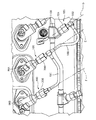
各ピッグテイルアッセンブリ168は、概してマニホールド連結アッセンブリ180、L型連結部182、T型連結部184、第1の燃料ノズル連結アッセンブリ186、L型連結部182とT型連結部184の間の第1の導管188、第2の燃料ノズル連結アッセンブリ190、およびT型連結部184と第2の燃料ノズル連結アッセンブリ190の間の第2の導管191を含む。特定のシステムおよびサブシステムが個別に画定されているが、それぞれのまたは任意のサブシステムは、別法で組み合わせられても、または分離されてもよいことを理解されたい。さらに「L」型および「T」型連結部などの特定の連結タイプが示されているが、さまざまな他の連結部も本明細書から利益を得ることを理解されたい。
Each
マニホールド連結アッセンブリ180、第1の燃料ノズル連結アッセンブリ186および第2の燃料ノズル連結アッセンブリ190のそれぞれは、Oリング198、200、202を備えるそれぞれの導かれた連結部192、194、196、およびBナット204、206、208を含み、Bナット204、206、208は、それぞれマニホールド継手110、第1の燃料噴射器86A、および第2の燃料噴射器86Bにねじ込まれてピッグテイルアッセンブリ168を固定する。
図6を参照すると、マニホールド連結アッセンブリ180は第1の軸Dを画定し、第1の燃料ノズル連結アッセンブリ186は第2の軸Eを画定し、第2の燃料ノズル連結アッセンブリ190は第3の軸Fを画定する。各軸は、ピッグテイルアッセンブリ168の各枝状部の自由状態を画定する。開示の非限定的一実施例では、第2の軸Eは第1の軸Dと第3の軸Fの間にあり、第1の軸Dは第2の軸Eに平行であり、第3の軸Fは第1の軸Dおよび第2の軸Eに非平行である。
Referring to FIG. 6, the
本開示の非限定的一実施例では、第1の燃料噴射器86Aおよび第2の燃料噴射器86Bは、エンジンの軸A(図7参照)を中心に約22.5度だけ分離され、二次燃料噴射器ポート210A、210Bはエンジンの軸A(図8参照)に対して約35度だけ傾斜される。さらに各燃料噴射器86A、86Bは、エンジンの軸Aに対して約92度の角度で傾けられてポートの軸G、H、I(図10参照)を画定する。
In one non-limiting example of the present disclosure, the
図11を参照すると、ピッグテイルアッセンブリ168は、Bナット204、206、208を後退(retract)させて軸Dおよび軸Eに沿って差し込まれる。ここでは、軸FおよびIがこの軸の差込み前の位置で約0.085インチ(2.2mm)(図12および図13参照)だけ同心から離れているように、導かれた継手196は、第2の燃料噴射器86Bの燃料噴射器ポート210Bと位置合わせされていない。すなわち、この軸の差込み前の位置に対して「自由状態」で、導かれた継手196は約7時の位置(図13参照)に向かって約0.085インチ(2.2mm)だけ軸Iから離れている。
Referring to FIG. 11,
マニホールド連結アッセンブリ180および第1の燃料ノズル連結アッセンブリ186は、それぞれ軸Gおよび軸Hに沿って同軸上に差し込まれる。すなわち、導かれた継手192、194は、軸GおよびHに沿って軸方向に直接差し込まれる。したがって、導かれた継手194を第1の燃料噴射器86Aの燃料噴射器ポート210Aと係合させるために、より短い長さの第1の導管188を曲げるまたは変形させる必要がない。しかし第2の導管191は、この軸の差込み前の位置では第2の燃料噴射器86Bの軸Iから外れている。しかし第2の導管191は比較的長く、したがって第2の燃料噴射器86Bの燃料噴射器ポート210Bとの初期係合のためにわずかに偏向させるようにより可撓性を有する。
図14を参照すると、ピッグテイルアッセンブリ168は、軸D、G、およびE、Hに沿って軸方向に移動され、第2の導管191は一時的に偏向されて、導かれた継手196を軸Iに沿って偏角の第2の燃料噴射器86Bと位置合わせさせる。すなわちこの軸位置で、第2の導管191は一時的に偏向され、適切な挿入に対して自由状態ではない。
Referring to FIG. 14,
図15を参照すると、導かれた継手196は、第2の燃料噴射器86Bの燃料噴射器ポート210Bと完全に係合されており、この完全に差し込まれた軸位置で第2の導管191は再度その「自由状態」にある(図16参照)。
Referring to FIG. 15, the guided
図17および図18を参照すると、次いでBナット204、206、208が固定される。より近い燃料ノズルと平行のままであるという概念により、複数の燃料ノズルを供給するピッグテイル168を使用して、差込み中にクロススレッディングまたはOリング切断の懸念が除去されていない場合でも低減する/最小にすることができる。
Referring to FIGS. 17 and 18, the
「前方」、「後方」、「上部」、「下部」、「上方」および「下方」などの相対位置用語は、標準の作動姿勢を基準とし、それ以外を制限すると考えられるべきではないことを理解されたい。 Relative position terms such as “front”, “rear”, “upper”, “lower”, “upper” and “lower” are relative to the standard operating posture and should not be considered as limiting otherwise. I want you to understand.
同じ参照番号は、いくつかの図面を通して対応するまたは類似の要素を同定することを理解されたい。また特定の構成要素の配置が示された実施例に開示されているが、他の配置も本明細書から利益を得ることも理解されたい。 It should be understood that like reference numerals identify corresponding or similar elements throughout the several views. Also, although specific component arrangements are disclosed in the illustrated embodiments, it should be understood that other arrangements may benefit from this specification.
特定のステップシーケンスが示され、説明され、また主張されているが、ステップは、別段に示されない限り任意の順番で実行され、分離され、または組み合わされてもよく、依然として本開示から利益を得ることを理解されたい。 Although a particular step sequence is shown, described, and claimed, the steps may be performed, separated, or combined in any order unless otherwise indicated, and still benefit from this disclosure. Please understand that.
前述の説明は、その中の特徴によって画定されるのではなく、むしろ例示である。さまざまな非限定的実施例が本明細書に開示されているが、さまざまな修正形態および変形形態が、上の教示を考慮して添付の特許請求の範囲内に収まることが当業者には理解されるはずである。したがって、添付の特許請求の範囲内で、本開示は具体的に記載された以外で実行されてもよいことを理解されたい。そのため添付の特許請求の範囲を検討して、真の範囲および内容を決定されるべきである。 The foregoing description is illustrative rather than defined by the features therein. While various non-limiting examples have been disclosed herein, those skilled in the art will recognize that various modifications and variations are within the scope of the appended claims in view of the above teachings. Should be done. Accordingly, it is to be understood that, within the scope of the appended claims, the present disclosure may be practiced other than as specifically described. For that reason, the following claims should be studied to determine the true scope and content.
20…ガスタービンエンジン
102…燃料供給マニホールド
168…ピッグテイルアッセンブリ
180…マニホールド連結アッセンブリ
186…第1の燃料ノズル連結アッセンブリ
188…第1の導管
190…第2の燃料ノズル連結アッセンブリ
191…第2の導管
D…第1の軸
E…第2の軸
F…第3の軸
DESCRIPTION OF
Claims (20)
第2の軸に沿って画定された第2の連結アッセンブリであって、前記第2軸は前記第1の軸に平行である、第2の連結アッセンブリと、
前記第1の連結アッセンブリと前記第2の連結アッセンブリの間にある第1の導管と、
第3の軸を画定する第3の連結アッセンブリであって、前記第3の軸は前記第2の軸に非平行である、第3の連結アッセンブリと、
前記第2の連結アッセンブリと前記第3の連結アッセンブリの間にある第2の導管と、
を備えることを特徴とする、ガスタービンエンジン用の燃料供給マニホールドアッセンブリのピッグテイルアッセンブリ。 A first coupling assembly defined along a first axis;
A second coupling assembly defined along a second axis, wherein the second axis is parallel to the first axis;
A first conduit between the first coupling assembly and the second coupling assembly;
A third coupling assembly defining a third axis, wherein the third axis is non-parallel to the second axis;
A second conduit between the second coupling assembly and the third coupling assembly;
A pigtail assembly of a fuel supply manifold assembly for a gas turbine engine.
前記マニホールド連結部に隣接したL型連結部であって、前記L型連結部および前記マニホールド連結部は、第1の軸に沿って画定される、L型連結部と、
第1の燃料ノズル連結部と、
前記第1の燃料ノズル連結部に隣接したT型連結部であって、前記T型連結部および前記第1の燃料マニホールド連結部は第2の軸に沿って画定され、前記第2の軸は前記第1の軸に平行である、T型連結部と、
前記L型連結部と前記T型連結部の間にある第1の導管と、
第3の軸を画定する第2の燃料ノズル連結部と、
前記T型連結部と前記第2の燃料ノズル連結部の間にある第2の導管と、
を備えることを特徴とする、ガスタービンエンジン用の燃料供給マニホールドアッセンブリのピッグテイルアッセンブリ。 Manifold connection part,
An L-shaped coupling part adjacent to the manifold coupling part, wherein the L-shaped coupling part and the manifold coupling part are defined along a first axis;
A first fuel nozzle connection;
A T-type connection part adjacent to the first fuel nozzle connection part, wherein the T-type connection part and the first fuel manifold connection part are defined along a second axis, and the second axis is A T-shaped coupling portion parallel to the first axis;
A first conduit between the L-shaped connection and the T-shaped connection;
A second fuel nozzle connection defining a third axis;
A second conduit between the T-shaped connection and the second fuel nozzle connection;
A pigtail assembly of a fuel supply manifold assembly for a gas turbine engine.
第2の連結アッセンブリを第2の軸に沿って第1の燃料ノズルに位置合わせすることであって、前記第2の軸が前記第1の軸に平行であり、前記第1の連結アッセンブリが、第1の導管を通して前記第2の連結アッセンブリと流体連通するように、位置合わせし、
第3の連結アッセンブリを第3の軸に沿って第2の燃料ノズルに位置合わせすることであって、前記第3の軸が前記第2の軸に非平行であり、前記第2の連結アッセンブリが、第2の導管を通して前記第3の連結アッセンブリと流体連通するように、位置合わせする、
ことを含むことを特徴とする、ガスタービンエンジン用の燃料供給マニホールドのピッグテイルアッセンブリを組み立てる方法。 Aligning the first coupling assembly with the manifold joint along the first axis;
Aligning a second coupling assembly with a first fuel nozzle along a second axis, wherein the second axis is parallel to the first axis and the first coupling assembly is Aligning in fluid communication with the second coupling assembly through the first conduit;
Aligning a third coupling assembly with a second fuel nozzle along a third axis, wherein the third axis is non-parallel to the second axis and the second coupling assembly; Is in fluid communication with the third coupling assembly through a second conduit.
A method of assembling a pigtail assembly of a fuel supply manifold for a gas turbine engine.
前記第2の連結アッセンブリの「B」ナットを前記第1の燃料ノズルに螺合させ、
前記第3の連結アッセンブリの「B」ナットを前記第2の燃料ノズルに螺合させる、
ことをさらに含むことを特徴とする請求項18に記載の方法。 Threading the "B" nut of the first coupling assembly into the manifold joint;
Threading the "B" nut of the second coupling assembly into the first fuel nozzle;
Threading the "B" nut of the third coupling assembly into the second fuel nozzle;
The method of claim 18 further comprising:
Applications Claiming Priority (2)
| Application Number | Priority Date | Filing Date | Title |
|---|---|---|---|
| US201461941851P | 2014-02-19 | 2014-02-19 | |
| US61/941,851 | 2014-02-19 |
Publications (1)
| Publication Number | Publication Date |
|---|---|
| JP2015155698A true JP2015155698A (en) | 2015-08-27 |
Family
ID=52484382
Family Applications (1)
| Application Number | Title | Priority Date | Filing Date |
|---|---|---|---|
| JP2015030533A Pending JP2015155698A (en) | 2014-02-19 | 2015-02-19 | Fuel manifold for gas turbine engine |
Country Status (3)
| Country | Link |
|---|---|
| US (1) | US9732960B2 (en) |
| EP (1) | EP2910751B1 (en) |
| JP (1) | JP2015155698A (en) |
Families Citing this family (5)
| Publication number | Priority date | Publication date | Assignee | Title |
|---|---|---|---|---|
| US11092084B2 (en) * | 2016-05-26 | 2021-08-17 | General Electric Company | Fuel delivery system for a gas turbine engine |
| US20190107285A1 (en) * | 2017-10-06 | 2019-04-11 | Pratt & Whitney Canada Corp. | Segmented fuel distributor |
| US11156162B2 (en) | 2018-05-23 | 2021-10-26 | General Electric Company | Fluid manifold damper for gas turbine engine |
| US11506125B2 (en) | 2018-08-01 | 2022-11-22 | General Electric Company | Fluid manifold assembly for gas turbine engine |
| KR102367002B1 (en) * | 2020-08-28 | 2022-02-23 | 두산중공업 주식회사 | Tensioning assembling structure of tie rod and gas turbine comprising the same and Tensioning assembling method of tie rod |
Family Cites Families (14)
| Publication number | Priority date | Publication date | Assignee | Title |
|---|---|---|---|---|
| US2806354A (en) | 1951-04-05 | 1957-09-17 | Rolls Royce | Fuel system with means to compensate for variations in liquid head due to accelerations acting on the fuel system |
| US3775975A (en) * | 1972-09-05 | 1973-12-04 | Gen Electric | Fuel distribution system |
| US5031407A (en) * | 1989-06-06 | 1991-07-16 | Allied-Signal Inc. | Apparatus for use in a fuel delivery system for a gas turbine engine |
| US5197288A (en) * | 1991-12-06 | 1993-03-30 | United Technologies Corporation | Detachable fuel manifold for gas turbine engines |
| US5390498A (en) * | 1994-02-15 | 1995-02-21 | General Electric Company | Fuel distribution assembly |
| US5927067A (en) | 1997-11-13 | 1999-07-27 | United Technologies Corporation | Self-cleaning augmentor fuel manifold |
| US6038852A (en) | 1997-12-05 | 2000-03-21 | United Technologies Corporation | Wear resistant augmentor fuel manifold clamp |
| US7647775B2 (en) | 2005-06-30 | 2010-01-19 | United Technologies Corporation | Augmentor spray bars |
| US7578131B2 (en) | 2005-06-30 | 2009-08-25 | United Technologies Corporation | Augmentor spray bar mounting |
| US7648103B2 (en) * | 2006-12-13 | 2010-01-19 | EMBRAER—Empresa Brasileira de Aeronautica S.A. | Aircraft fuel tanks, systems and methods for increasing an aircraft's on-board fuel capacity |
| US9140453B2 (en) | 2011-12-20 | 2015-09-22 | Pratt & Whitney Canada Corp. | Fuel manifold with jumper tubes |
| US9803498B2 (en) | 2012-10-17 | 2017-10-31 | United Technologies Corporation | One-piece fuel nozzle for a thrust engine |
| US9291098B2 (en) * | 2012-11-14 | 2016-03-22 | General Electric Company | Turbomachine and staged combustion system of a turbomachine |
| GB201313034D0 (en) * | 2013-07-22 | 2013-09-04 | Rolls Royce Plc | A fuel manifold and fuel injector arrangement for a combustion chamber |
-
2015
- 2015-02-19 US US14/626,611 patent/US9732960B2/en active Active
- 2015-02-19 EP EP15155794.9A patent/EP2910751B1/en active Active
- 2015-02-19 JP JP2015030533A patent/JP2015155698A/en active Pending
Also Published As
| Publication number | Publication date |
|---|---|
| EP2910751B1 (en) | 2016-12-21 |
| US9732960B2 (en) | 2017-08-15 |
| EP2910751A1 (en) | 2015-08-26 |
| US20150233581A1 (en) | 2015-08-20 |
Similar Documents
| Publication | Publication Date | Title |
|---|---|---|
| JP6769714B2 (en) | Fuel supply system for gas turbine combustors | |
| US10132244B2 (en) | Fuel manifold for a gas turbine engine | |
| JP2015155698A (en) | Fuel manifold for gas turbine engine | |
| EP2530381B1 (en) | Loading assembly for a turbine system | |
| US20130174562A1 (en) | Gas turbine engine, combustor and dome panel | |
| US20120304665A1 (en) | Mount device for transition duct in turbine system | |
| US10837635B2 (en) | Fuel swirler with anti-rotation features | |
| US10088166B2 (en) | Swirler mount interface for gas turbine engine combustor | |
| US20190285276A1 (en) | Castellated combustor panels | |
| US11226102B2 (en) | Fuel nozzle for a gas turbine engine | |
| US20140048166A1 (en) | Pivoting ball stop for exhaust duct liner hanger | |
| JP6595191B2 (en) | Method of mounting a manifold joint for a gas turbine engine and a fuel supply manifold assembly for a gas turbine engine | |
| US10634344B2 (en) | Fuel nozzle assembly with fuel purge | |
| US11415320B2 (en) | Combustor cooling panel with flow guide | |
| JP2018048630A (en) | Mounting assembly for gas turbine engine fluid conduit | |
| EP3767176A1 (en) | Gas turbine engine component | |
| US10669942B2 (en) | Endcover assembly for a combustor | |
| US11209162B2 (en) | Combustor panel stud cooling effusion through heat transfer augmentors | |
| US11846419B2 (en) | Dome-deflector joint cooling arrangement |