JP2015149316A5 - - Google Patents
Download PDFInfo
- Publication number
- JP2015149316A5 JP2015149316A5 JP2014019768A JP2014019768A JP2015149316A5 JP 2015149316 A5 JP2015149316 A5 JP 2015149316A5 JP 2014019768 A JP2014019768 A JP 2014019768A JP 2014019768 A JP2014019768 A JP 2014019768A JP 2015149316 A5 JP2015149316 A5 JP 2015149316A5
- Authority
- JP
- Japan
- Prior art keywords
- measurement
- substrate
- exposure
- exposure apparatus
- shot
- Prior art date
- Legal status (The legal status is an assumption and is not a legal conclusion. Google has not performed a legal analysis and makes no representation as to the accuracy of the status listed.)
- Granted
Links
- 238000005259 measurement Methods 0.000 claims description 62
- 239000000758 substrate Substances 0.000 claims description 30
- 238000001514 detection method Methods 0.000 claims description 18
- 230000000875 corresponding Effects 0.000 claims description 3
- 238000004519 manufacturing process Methods 0.000 claims 1
- 238000000034 method Methods 0.000 claims 1
- 239000002245 particle Substances 0.000 claims 1
Images

Description
上記目的を達成するために、本発明の一側面としての露光装置は、基板上の複数のショット領域のそれぞれに走査露光を行う露光装置であって、前記基板の走査に伴い前記基板上の計測箇所に関して露光領域内において検出を行う第1検出と、前記基板の走査に伴い前記第1検出に先立って前記計測箇所に関して検出を行う第2検出とを行い、前記第1検出の結果および前記第2検出の結果のそれぞれに基づいて前記基板の高さを計測する計測部と、第1ショット領域の走査露光に伴い前記第1検出の結果に基づいて前記計測部により得られた計測結果と目標高さとの差が許容範囲に収まっているかに基づいて、前記第1ショット領域とは異なる第2ショット領域に関して、前記第2検出の結果に基づいて前記計測部による計測を最初に行う第1計測箇所を、それとして予め決められた計測箇所から変更する処理部と、を含むことを特徴とする。 In order to achieve the above object, an exposure apparatus according to one aspect of the present invention is an exposure apparatus that performs scanning exposure on each of a plurality of shot regions on a substrate, and performs measurement on the substrate as the substrate is scanned. a first detection for detecting the exposure area with respect to position, performs a second detection to detect for said measurement point prior to the first detection with the scanning of the substrate, the first detection result and the second a measuring unit for measuring the height of the substrate based on each of the two detection results, the measurement result and the target obtained by the measuring unit based on the scanning exposure with the first detection result of the first shot area the difference between the height based on whether within the allowable range, first perform measurement by the measurement unit based on a different relation to the second shot region, the second detection result from the first shot area 1 measurement points, characterized in that it comprises a processing unit for changing the predetermined measurement point as it a.
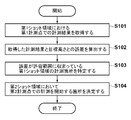
以下に、第2ショット領域(図4ではショット領域15a2)において第2計測点(計測点30b1〜30b3)での計測を開始する箇所を処理部20aにより決定する方法について、図7を参照しながら説明する。図7は、第2ショット領域において第2計測点での計測を開始する箇所を決定する方法を示すフローチャートである。S101では、処理部20aは、第1ショット領域に設けられた複数の計測箇所40を第1計測点(計測点30a1〜30a3)で計測した計測結果を取得する。S102では、処理部20aは、取得した計測結果と目標高さ(フォーカス位置)との誤差(差)を算出する。S103では、処理部20aは、S102において算出した誤差が許容範囲に収まっている第1ショット領域の計測箇所40を特定する。S104では、処理部20aは、特定した第1ショット領域の計測箇所40に対応する第2ショット領域の計測箇所40の第2計測点での計測を省略するように、第2ショット領域において第2計測点での計測を開始する箇所(第1計測箇所)を決定する。これにより、処理部20aは、第2ショット領域の走査露光を開始するまでに基板ステージ16をステップ移動させるための移動経路(第2移動経路)を、第1移動経路より短くなるように決定することができる。換言すると、処理部20aは、第1ショット領域に対する走査露光と第2ショット領域に対する走査露光との間の基板ステージ16のステップ移動に係る移動経路(第2移動経路)を決定することができる。即ち、基板ステージ16をステップ移動させる際のスリット光の走査経路21aを短くすることができる。ここで、第1移動経路とは、第1ショット領域の走査露光を開始するまでに基板ステージ16をステップ移動させた移動経路のことをいう。 Hereinafter, a method of determining the second shot area processing unit 20a where to start measuring at the second measurement point in the (shot area 15a 2 in FIG. 4) (measurement point 30b 1 ~30b 3), Figure 7 The description will be given with reference. FIG. 7 is a flowchart showing a method for determining a location where measurement at the second measurement point is started in the second shot region. In S101, the processing unit 20a acquires measurement results obtained by measuring a plurality of measurement points 40 provided in the first shot area at the first measurement points (measurement points 30a 1 to 30a 3 ). In S102, the processing unit 20a calculates an error (difference) between the acquired measurement result and the target height (focus position). In S103, the processing unit 20a identifies the measurement location 40 of the first shot area where the error calculated in S102 is within the allowable range. In S104, the processing section 20a, so as to omit the measurement at the second measuring point of the measurement point 40 of the second shot region corresponding to the measurement point 40 of the first shot region identified, the second in the second shot region A location (first measurement location) where measurement at the measurement point is started is determined. As a result, the processing unit 20a determines a movement path (second movement path) for moving the substrate stage 16 in steps until the scanning exposure of the second shot area is started to be shorter than the first movement path. be able to. In other words, the processing unit 20a can determine a movement path (second movement path) related to the step movement of the substrate stage 16 between the scanning exposure for the first shot area and the scanning exposure for the second shot area. That is, it is possible to shorten the scanning path 21a for slit light when the substrate stage 16 is moved stepwise. Here, the first movement path refers to a movement path in which the substrate stage 16 is moved stepwise before the scanning exposure of the first shot area is started.
Claims (16)
前記基板の走査に伴い前記基板上の計測箇所に関して露光領域内において検出を行う第1検出と、前記基板の走査に伴い前記第1検出に先立って前記計測箇所に関して検出を行う第2検出とを行い、前記第1検出の結果および前記第2検出の結果のそれぞれに基づいて前記基板の高さを計測する計測部と、
第1ショット領域の走査露光に伴い前記第1検出の結果に基づいて前記計測部により得られた計測結果と目標高さとの差が許容範囲に収まっているかに基づいて、前記第1ショット領域とは異なる第2ショット領域に関して、前記第2検出の結果に基づいて前記計測部による計測を最初に行う第1計測箇所を、それとして予め決められた計測箇所から変更する処理部と、
を含むことを特徴とする露光装置。 An exposure apparatus that performs scanning exposure on each of a plurality of shot areas on a substrate,
A first detection for detecting the exposure area with respect to the measurement point on the substrate with the scanning of the substrate, and a second detection for detecting with respect to the measurement point prior to the first detection with the scanning of the substrate performed, a measuring unit for the measuring the height of the substrate on the basis of each of the first result of the detection and the second detection result,
Based on whether the difference between the measurement results obtained by the measurement unit based on the first detection result with the scanning exposure with the target height of the first shot area is within the allowable range, said first shot region A processing unit that changes a first measurement location where measurement is first performed by the measurement unit based on a result of the second detection from a measurement location determined in advance as to a different second shot region,
An exposure apparatus comprising:
前記処理部は、前記第1計測箇所に基づいて、前記第1ショット領域に対する走査露光と前記第2ショット領域に対する走査露光との間の前記ステージのステップ移動に係る経路を決定することを特徴とする請求項1に記載の露光装置。 Including a movable stage holding the substrate;
The processing unit determines a path related to step movement of the stage between scanning exposure for the first shot area and scanning exposure for the second shot area based on the first measurement location. The exposure apparatus according to claim 1.
前記基板の走査に伴い前記基板上の複数の計測箇所のそれぞれに関して前記露光領域内において前記基板の高さの計測を行う第1計測と、前記基板の走査に伴い前記第1計測に先立って前記複数の計測箇所のそれぞれに関して前記基板の高さの計測を行う第2計測とを行う計測部と、A first measurement for measuring the height of the substrate in the exposure region for each of a plurality of measurement locations on the substrate as the substrate is scanned, and the first measurement prior to the first measurement as the substrate is scanned. A measurement unit that performs a second measurement for measuring the height of the substrate with respect to each of a plurality of measurement points;
第1ショット領域の走査露光に伴って得られた前記第1計測の結果と目標高さとの差が許容範囲に収まっているかに基づいて、前記第1ショット領域とは異なる第2ショット領域に関して、前記第2計測を最初に行う第1計測箇所を、予め決められた複数の計測箇所のうちから選択する処理部と、Based on whether the difference between the target height and the result of the first measurement obtained with the scanning exposure of the first shot area is within an allowable range, the second shot area different from the first shot area, A processing unit that selects a first measurement point where the second measurement is first performed from a plurality of predetermined measurement points;
を含むことを特徴とする露光装置。An exposure apparatus comprising:
前記工程で露光を行われた前記基板を現像する工程と、
を含むことを特徴とする物品の製造方法。 A step of exposing the substrate using the exposure apparatus according to any one of claims 1 to 15 ,
Developing the substrate exposed in the step;
A method for producing an article comprising:
Priority Applications (2)
| Application Number | Priority Date | Filing Date | Title |
|---|---|---|---|
| JP2014019768A JP6267530B2 (en) | 2014-02-04 | 2014-02-04 | Exposure apparatus and article manufacturing method |
| US14/608,731 US9746789B2 (en) | 2014-02-04 | 2015-01-29 | Exposure apparatus, and method of manufacturing article |
Applications Claiming Priority (1)
| Application Number | Priority Date | Filing Date | Title |
|---|---|---|---|
| JP2014019768A JP6267530B2 (en) | 2014-02-04 | 2014-02-04 | Exposure apparatus and article manufacturing method |
Publications (3)
| Publication Number | Publication Date |
|---|---|
| JP2015149316A JP2015149316A (en) | 2015-08-20 |
| JP2015149316A5 true JP2015149316A5 (en) | 2017-03-16 |
| JP6267530B2 JP6267530B2 (en) | 2018-01-24 |
Family
ID=53754743
Family Applications (1)
| Application Number | Title | Priority Date | Filing Date |
|---|---|---|---|
| JP2014019768A Active JP6267530B2 (en) | 2014-02-04 | 2014-02-04 | Exposure apparatus and article manufacturing method |
Country Status (2)
| Country | Link |
|---|---|
| US (1) | US9746789B2 (en) |
| JP (1) | JP6267530B2 (en) |
Cited By (1)
| Publication number | Priority date | Publication date | Assignee | Title |
|---|---|---|---|---|
| JP7022611B2 (en) | 2018-02-06 | 2022-02-18 | キヤノン株式会社 | Exposure device control method, exposure device, and article manufacturing method |
Families Citing this family (4)
| Publication number | Priority date | Publication date | Assignee | Title |
|---|---|---|---|---|
| JP6806509B2 (en) * | 2016-09-15 | 2021-01-06 | キヤノン株式会社 | Method of manufacturing exposure equipment and articles |
| CA2962809C (en) * | 2017-03-31 | 2019-02-26 | Centre De Recherche Industrielle Du Quebec | System and method for color scanning a moving article |
| JP6882091B2 (en) * | 2017-06-21 | 2021-06-02 | キヤノン株式会社 | Exposure equipment and manufacturing method of articles |
| JP7137363B2 (en) * | 2018-06-11 | 2022-09-14 | キヤノン株式会社 | Exposure method, exposure apparatus, article manufacturing method and measurement method |
Family Cites Families (8)
| Publication number | Priority date | Publication date | Assignee | Title |
|---|---|---|---|---|
| JPH09306833A (en) * | 1996-03-14 | 1997-11-28 | Nikon Corp | Exposing method |
| JP2008277468A (en) * | 2007-04-27 | 2008-11-13 | Canon Inc | Aligner, and device manufacturing method |
| JP2008288347A (en) * | 2007-05-16 | 2008-11-27 | Canon Inc | Aligner and method of manufacturing device |
| JP4953923B2 (en) * | 2007-05-30 | 2012-06-13 | キヤノン株式会社 | Exposure apparatus and device manufacturing method |
| JP5084432B2 (en) * | 2007-10-05 | 2012-11-28 | キヤノン株式会社 | Exposure method, exposure apparatus, and device manufacturing method |
| JP2009186628A (en) * | 2008-02-05 | 2009-08-20 | Ricoh Co Ltd | Electron beam drawing method and electron beam drawing device |
| JP2009302344A (en) * | 2008-06-13 | 2009-12-24 | Canon Inc | Exposure apparatus, and device manufacturing method |
| JP5498243B2 (en) * | 2010-05-07 | 2014-05-21 | キヤノン株式会社 | Exposure apparatus, exposure method, and device manufacturing method |
-
2014
- 2014-02-04 JP JP2014019768A patent/JP6267530B2/en active Active
-
2015
- 2015-01-29 US US14/608,731 patent/US9746789B2/en active Active
Cited By (1)
| Publication number | Priority date | Publication date | Assignee | Title |
|---|---|---|---|---|
| JP7022611B2 (en) | 2018-02-06 | 2022-02-18 | キヤノン株式会社 | Exposure device control method, exposure device, and article manufacturing method |
Similar Documents
| Publication | Publication Date | Title |
|---|---|---|
| JP2015149316A5 (en) | ||
| JP2018169204A5 (en) | ||
| JP2011101056A5 (en) | Exposure apparatus and exposure method | |
| JP2011238707A5 (en) | ||
| JP6296206B2 (en) | Shape measuring apparatus and shape measuring method | |
| JP2016533484A5 (en) | ||
| JP2017107201A (en) | Dynamic autofocus system | |
| US10118250B1 (en) | In-situ laser beam position and spot size sensor and high speed scanner calibration, wafer debonding method | |
| JP2017126870A5 (en) | ||
| JP2012004461A5 (en) | ||
| JP2009199049A5 (en) | ||
| JP2015226579A5 (en) | ||
| JP2016072507A5 (en) | ||
| JP2013198721A5 (en) | ||
| JPWO2015104799A1 (en) | Appearance inspection apparatus and appearance inspection method | |
| JP2009168510A (en) | Method for setting amount of illumination light in image measuring apparatus | |
| JP2018022114A5 (en) | ||
| JP2013021215A5 (en) | ||
| JP2012173709A5 (en) | ||
| JP2016080475A5 (en) | ||
| JP2014029956A5 (en) | ||
| JP2018045147A5 (en) | ||
| JP2017015994A5 (en) | ||
| JP2016502094A5 (en) | ||
| JP2015070057A5 (en) |