JP2015146261A - Socket and lighting device using the same - Google Patents
Socket and lighting device using the same Download PDFInfo
- Publication number
- JP2015146261A JP2015146261A JP2014018635A JP2014018635A JP2015146261A JP 2015146261 A JP2015146261 A JP 2015146261A JP 2014018635 A JP2014018635 A JP 2014018635A JP 2014018635 A JP2014018635 A JP 2014018635A JP 2015146261 A JP2015146261 A JP 2015146261A
- Authority
- JP
- Japan
- Prior art keywords
- socket
- pin
- space
- straight tube
- housing
- Prior art date
- Legal status (The legal status is an assumption and is not a legal conclusion. Google has not performed a legal analysis and makes no representation as to the accuracy of the status listed.)
- Granted
Links
- 238000005286 illumination Methods 0.000 claims abstract description 74
- 238000005192 partition Methods 0.000 claims description 4
- 230000001419 dependent effect Effects 0.000 claims 2
- 210000000078 claw Anatomy 0.000 description 8
- 238000004519 manufacturing process Methods 0.000 description 7
- 238000000034 method Methods 0.000 description 5
- 238000003780 insertion Methods 0.000 description 3
- 230000037431 insertion Effects 0.000 description 3
- 239000011810 insulating material Substances 0.000 description 3
- 230000002093 peripheral effect Effects 0.000 description 3
- -1 polybutylene terephthalate Polymers 0.000 description 3
- 229920001707 polybutylene terephthalate Polymers 0.000 description 3
- 229920000515 polycarbonate Polymers 0.000 description 3
- 239000004417 polycarbonate Substances 0.000 description 3
- 229920005992 thermoplastic resin Polymers 0.000 description 3
- 230000015572 biosynthetic process Effects 0.000 description 2
- 238000010586 diagram Methods 0.000 description 2
- 230000002265 prevention Effects 0.000 description 2
- 229910000906 Bronze Inorganic materials 0.000 description 1
- OAICVXFJPJFONN-UHFFFAOYSA-N Phosphorus Chemical compound [P] OAICVXFJPJFONN-UHFFFAOYSA-N 0.000 description 1
- 239000010974 bronze Substances 0.000 description 1
- KUNSUQLRTQLHQQ-UHFFFAOYSA-N copper tin Chemical compound [Cu].[Sn] KUNSUQLRTQLHQQ-UHFFFAOYSA-N 0.000 description 1
- 230000000694 effects Effects 0.000 description 1
- 239000011521 glass Substances 0.000 description 1
- 238000009434 installation Methods 0.000 description 1
- 239000002184 metal Substances 0.000 description 1
- 230000003287 optical effect Effects 0.000 description 1
- 239000003973 paint Substances 0.000 description 1
- 229920005989 resin Polymers 0.000 description 1
- 239000011347 resin Substances 0.000 description 1
- 239000004065 semiconductor Substances 0.000 description 1
Images


Abstract
Description
本発明は、直管形照明ランプを保持するソケット及びこれを用いた照明器具に関するものである。 The present invention relates to a socket for holding a straight tube illumination lamp and a lighting fixture using the socket.
照明器具には、直管形照明ランプの口金部分を支持するソケットが設けられている。ここで、直管形照明ランプを、長手方向に複数並べて配置するために、ソケットを連結する連結部品が提案されている(たとえば、特許文献1参照)。特許文献1に記載の連結部品は、一方の直管形照明ランプの端部の口金を支持するソケットが連結部品本体の一方側に嵌められ、他方の直管形照明ランプの端部の口金を支持するソケットが連結部品本体の他方側に嵌め込まれるようになっている。
The lighting fixture is provided with a socket for supporting the base portion of the straight tube type lighting lamp. Here, in order to arrange a plurality of straight tube illumination lamps in the longitudinal direction, a connecting component for connecting sockets has been proposed (for example, see Patent Document 1). In the connecting component described in
また、ランプソケット本体の両面に直管蛍光ランプを取り付けられる構造を有するランプソケット(以下、共用ランプソケットとも称する)がある(たとえば、特許文献2参照)。特許文献2に記載の技術は、ソケット本体の一端側に、一方の直管形照明ランプの端部の口金が取り付けられる第1の構造が形成され、他端側に他方の直管形照明ランプの端部の口金が取り付けられる第2の構造が形成されているものである。また、第1の構造側と第2の構造側とを仕切るように蓋体が形成されている。特許文献2に記載の技術では、第1の構造、第2の構造及び蓋体が一体的に形成されている。 Further, there is a lamp socket (hereinafter also referred to as a common lamp socket) having a structure in which a straight tube fluorescent lamp can be attached to both surfaces of a lamp socket body (see, for example, Patent Document 2). In the technique described in Patent Document 2, a first structure in which a base of one end of a straight tube illumination lamp is attached to one end of a socket body is formed, and the other straight tube illumination lamp is disposed on the other end. A second structure to which a base at the end is attached is formed. Further, a lid is formed so as to partition the first structure side and the second structure side. In the technique described in Patent Document 2, the first structure, the second structure, and the lid are integrally formed.
特許文献1に記載の技術は、ソケットを取り付ける連結部品の分だけ長手方向の厚みが増加してしまい、直管形照明ランプが設置される照明装置が大型化してしまうという課題がある。
The technique described in
特許文献2に記載の技術は、共用ランプソケットとは別のランプソケット(以下では、非共用ランプソケットとも称する)を、共用ランプソケットの部材を流用して製造しにくい。具体的には、照明装置には、共用ランプソケット以外に、一方の直管形照明ランプ及び他方の直管形照明ランプの端部を支持する非共用ランプソケットが取り付けられている。しかし、共用ランプソケットは、第1の構造、第2の構造及び蓋体が一体的に形成されているものである。このため、第1の構造(又は第2の構造)及び蓋体を要する非共用ランプソケットを製造するにあたって、第2の構造(又は第1の構造)が一体形成されてしまっている共用ランプソケットを使用することができず、製造コストが増大するという課題がある。また、一対のランプソケットを設計する手間が増大する分、開発コストも増大してしまうという課題がある。 The technique described in Patent Document 2 is difficult to manufacture a lamp socket (hereinafter also referred to as a non-shared lamp socket) different from the shared lamp socket by diverting a member of the shared lamp socket. Specifically, in addition to the common lamp socket, a non-common lamp socket that supports the end portion of one straight tube illumination lamp and the other straight tube illumination lamp is attached to the lighting device. However, the common lamp socket is one in which the first structure, the second structure, and the lid are integrally formed. For this reason, in manufacturing the non-shared lamp socket that requires the first structure (or the second structure) and the lid, the shared lamp socket in which the second structure (or the first structure) is integrally formed. Cannot be used, and the manufacturing cost increases. In addition, there is a problem that the development cost increases because the effort for designing the pair of lamp sockets increases.
本発明は、上記のような課題を解決するためになされたものであり、照明装置の大型化を抑制すること、及び、コストアップを抑制することを実現したソケット及びこれを用いた照明器具を提供することを目的としている。 The present invention has been made in order to solve the above-described problems, and provides a socket and a lighting apparatus using the same that can suppress an increase in the size of a lighting device and a cost increase. It is intended to provide.
本発明のソケットは、長尺状の発光管と、発光管の端部に取り付けられ、ランプピンが設けられた口金とを有する直管形照明ランプが取り付けられるソケットであって、第1の開口部及び第1の空間を有し、第1の直管形照明ランプの口金側が取り付けられる第1の筐体と第2の開口部及び第2の空間を有し、第2の直管形照明ランプの口金側が取り付けられる第2の筐体と、第1の筐体の第1の空間及び第2の筐体の第2の空間にそれぞれ設けられ、ランプピンに電気的に接続される複数のピン接触片と、第1の筐体の第1の開口部と第2の筐体の第2の開口部とに着脱自在に設けられ、第1の空間と第2の空間とを仕切る蓋体と、を有するものである。 The socket of the present invention is a socket to which a straight tube type illumination lamp having a long arc tube and a base provided with a lamp pin is attached to an end of the arc tube, and is a first opening. And a first casing, a first opening to which the base side of the first straight tube illumination lamp is attached, a second opening, and a second space, and a second straight tube illumination lamp A plurality of pin contacts which are respectively provided in the first housing of the first housing and the first space of the first housing and the second space of the second housing and are electrically connected to the lamp pins. A lid, which is detachably provided in the first opening of the first housing and the second opening of the second housing, and partitions the first space and the second space; It is what has.
本発明のソケットによれば、上記構成を有しているため、照明装置の大型化を抑制すること、及び、コストアップを抑制することを実現することができる。 According to the socket of this invention, since it has the said structure, it can implement | achieve suppressing the enlargement of an illuminating device and suppressing a cost increase.
実施の形態.
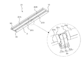
以下、図面を参照しながら本発明のソケット及びこれを用いた照明装置の実施形態について説明する。図1は実施の形態に係る第1のソケット30を用いた照明装置10の斜視図である。図1の照明装置10は、たとえば天井に埋め込まれて室内に設置されるものであって、第1の直管形照明ランプ20A及び第2の直管形照明ランプ20Bを駆動して照明を行うものである。この照明装置10は、器具本体11と、第1のソケット30と、第2のソケット80と、図示省略の電源装置とを有している。なお、この電源装置は、第1のソケット30を介して第1の直管形照明ランプ20A及び第2の直管形照明ランプ20Bに電力を供給するのに利用されるものである。
Embodiment.
Hereinafter, embodiments of a socket of the present invention and a lighting device using the same will be described with reference to the drawings. FIG. 1 is a perspective view of a
器具本体11は、第1の直管形照明ランプ20A及び第2の直管形照明ランプ20Bから発せられる光を反射する反射板3が取り付けられている。器具本体11の長手方向の両端側には第2のソケット80が配置されており、中央部には第1のソケット30が配置されている。
第1のソケット30の一方には、第1の直管形照明ランプ20Aが装着され、第1のソケット30の他方には、第2の直管形照明ランプ20Bが装着される。照明装置10には、2つの第1のソケット30が設けられているとともに、4つの第2のソケット80が設けられ、2つずつ第1の直管形照明ランプ20A及び第2の直管形照明ランプ20Bが設けられている。すなわち、照明装置10には、直管形照明ランプを2本直列に配置したものが、2列併設されている。第1のソケット30及び第2のソケット80は、図示しない点灯駆動装置に接続されており、点灯駆動装置から第1のソケット30及び第2のソケット80を介して第1の直管形照明ランプ20A及び第2の直管形照明ランプ20Bに電力が供給される。
The
The first straight
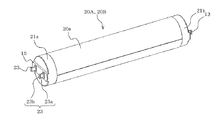
図2は、図1の照明装置10に取り付けられた第1の直管形照明ランプ20A(第2の直管形照明ランプ20B)の一例を示す斜視図である。図2の第1の直管形照明ランプ20A及び第2の直管形照明ランプ20Bは、たとえば直管形LEDランプであって、発光管20aと、発光管20aの両端にそれぞれ設けられた第1の口金21a及び第2の口金21bとを備える。
FIG. 2 is a perspective view showing an example of the first straight
ここで、昨今、直管蛍光ランプの代替として直管形LEDランプが販売されているが、口金として従来の直管蛍光ランプと同じG13口金が採用されているものが多い。そのため、従来の蛍光灯用照明器具に直管形LEDランプを取り付けることができるようになっている。しかし、直管形LEDランプは、使用可能(取り付け可能)な照明器具が指定されているものも多い(たとえば、電子安定器用、グロー安定器用など)。したがって、使用可能でない照明器具にユーザーが間違って取り付ける可能性があり、取り付けた直管形LEDランプ、安定器などが故障する恐れがある。このような間違いを防ぐために、従来のG13口金とは異なる新規な口金を備えた直管形LEDランプの規格が検討されている((社)日本電球工業会規格JEL801、JEL803、JEL907)。 Nowadays, straight tube LED lamps are being sold as an alternative to straight tube fluorescent lamps, but many of them employ the same G13 base as conventional straight tube fluorescent lamps. Therefore, it is possible to attach a straight tube LED lamp to a conventional fluorescent lamp. However, many straight tube LED lamps are designated as usable (attachable) lighting fixtures (for example, for electronic ballasts, glow ballasts, etc.). Therefore, there is a possibility that the user may mistakenly install the lighting fixture that cannot be used, and the installed straight tube LED lamp, ballast, or the like may break down. In order to prevent such a mistake, the standard of the straight tube | pipe type LED lamp provided with the new nozzle | cap | die different from the conventional G13 nozzle | cap | die is examined ((Corporation | KK Japan Light Bulb Industry Association standards JEL801, JEL803, JEL907).
このような背景から、第1の口金21a及び第2の口金21bは、JEL801規格のL形ピン口金GX16t−5、又はJEL803規格のL形ピン口金GZ16と呼ばれる口金が採用されている。第1の口金21aは、直流電流が給電される給電側口金(給電端子)であり、第2の口金21bは、落下防止機能を備えた接地側口金(アース端子)である。
From such a background, the
第1の直管形照明ランプ20A及び第2の直管形照明ランプ20Bは、LEDなどの複数の半導体発光素子が長手方向に配列された構造を有する。発光管20aは、長尺状に形成されたものであり、第1の直管形照明ランプ20A及び第2の直管形照明ランプ20BがLED照明である場合にはたとえば樹脂などで構成されるカバーで構成される。なお、第1の直管形照明ランプ20A及び第2の直管形照明ランプ20Bは、蛍光灯でもよい。蛍光灯である場合には、たとえば内周面に蛍光塗料などが塗布されたガラス管などで構成される。第2の口金21bには、1本のランプピン13が取り付けられており、第2の口金21bは、第2のソケット80側に装着される。一方、第1の口金21aは、第1のソケット30側に装着されるものであって、第1のソケット30に嵌め込まれる凸部15を有するとともに、凸部15上に1対のランプピン23が取り付けられている。ランプピン23は、略L字状に形成されたものであって、発光管20aの軸方向に延びた軸部23aと、軸部23aの先端から外方に突出した抜け止め部23bとを備えている。
The first straight
図3は、図1に示す第1のソケット30の一例の説明図である。なお、図3(a)が斜視図であり、図3(b)が第1のソケット30の縦断面図を模式的に示した図である。図4は、図1に示す第1のソケット30の分解斜視図である。図3及び図4を参照して第1のソケット30の第1の筐体31a及び第1の回転子40aなどについて説明する。第1のソケット30は、第1の直管形照明ランプ20Aの第1の口金21a及び第2の直管形照明ランプ20Bの第1の口金21aを保持するものであって、第1の筐体31aと、第2の筐体31bと、蓋体50と、第1のピン接触片70、第2のピン接触片60A、及び第3のピン接触片60Bとを備えている。
FIG. 3 is an explanatory diagram of an example of the
第1のソケット30は、内部が中空に形成されている箱体である。ここで、第1の筐体31aと蓋体50とは着脱自在であり、また、第2の筐体31bと蓋体50とは着脱自在であり、第1の筐体31aと、第2の筐体31bと、蓋体50とは別体である。
より詳細には、第1の筐体31a、第2の筐体31b及び蓋体50は、第1の筐体31aと蓋体50が嵌合するとともに第2の筐体31bと蓋体50とが嵌合する。そして、第1の筐体31aには、第1の開口部T1及び第1の空間S1が形成され、第2の筐体31bには、第2の開口部T2及び第2の空間S2が形成されている。そして、蓋体50は、第1の筐体31aの第1の開口部T1と第2の筐体31bの第2の開口部T2とに着脱自在に設けられ、第1の空間S1と第2の空間S2とを仕切るように設けられている。
第1の空間S1には、第1の回転子40a及び第2のピン接触片60Aなどが位置している。また、第1の空間S1には、第1のピン接触片70の一部も位置している。第1のピン接触片70は、後述する図5、6の蓋体50のスリット52を通過して第1の空間S1内にも入り込んでいる。また、第2の空間S2には、第2の回転子40b、第1のピン接触片70の一部、及び第3のピン接触片60Bなどが位置している。第1の筐体31a、第2の筐体31b及び蓋体50は、たとえばポリカーボネード、ポリブチレンテレフタレートなどの熱可塑性樹脂の絶縁材から構成される絶縁蓋である。
The
More specifically, the
The
第1の筐体31aには、第1の口金21aに対向する部位に、円形状の第1の開口部32が形成されており、第1の開口部32に第1の回転子40aが配置される。また、第1の開口部32の上部には切欠部42aが形成されており、切欠部42aから第1の口金21aの凸部15(図2参照)がスライドして挿入されるようになっている。第1の筐体31aの内周面には、蓋体50と嵌合するのに利用される嵌合凸部(図示省略)が形成されている。第1の筐体31aには、照明装置10の器具本体11の取り付けられる側に器具取付部34aが形成されている。
The
第1の回転子40aは、外形略円柱状に形成されたものであって、たとえばポリカーボネード、ポリブチレンテレフタレートなどの熱可塑性樹脂の絶縁材から構成されるものである。第1の回転子40aは、第1の筐体31a内において蓋体50の回転保持部53により回転自在に保持されており、第1の直管形照明ランプ20Aの第1の口金21aに接触する略円板状の接触面45aを有している。また、第1の回転子40aには、接触面45aを二分するように切り欠かれた凹部46aが形成されており、凹部46aには第1の口金21aの凸部15及びランプピン23が切欠部42aから挿入される。そして、第1の回転子40aは第1の直管形照明ランプ20Aの回転とともに第1の筐体31a及び蓋体50に対して回転する。
The
第2の筐体31bは、第1の筐体31aと同様の形状を有するものである。すなわち、第2の筐体31bは、第1の口金21aに対向する部位に、円形状の第2の開口部(図示省略)が形成されており、この第2の開口部に第2の回転子40bが配置される。また、第2の開口部の上部には切欠部42bが形成されており、切欠部42bから第1の口金21aの凸部15(図2参照)がスライドして挿入されるようになっている。第2の筐体31bの内周面には、蓋体50と嵌合するのに利用される嵌合受部33が形成されている。第2の筐体31bには、照明装置10の器具本体11の取り付けられる側に器具取付部34bが形成されている。
The
第2の回転子40bは、第1の回転子40aと同様の形状を有するものである。第2の回転子40bは、外形略円柱状に形成されたものであって、たとえばポリカーボネード、ポリブチレンテレフタレートなどの熱可塑性樹脂の絶縁材から構成されるものである。第2の回転子40bは、第2の筐体31b内において蓋体50の回転保持部53により回転自在に保持されており、第2の直管形照明ランプ20Bの第1の口金21aに接触する略円板状の接触面45aを有している。また、第2の回転子40bには、接触面45bを二分するように切り欠かれた凹部46bが形成されており、凹部46bには第1の口金21aの凸部15及びランプピン23が切欠部42bから挿入される。そして、第2の回転子40bは第2の直管形照明ランプ20Bの回転とともに第2の筐体31b及び蓋体50に対して回転する。
The
このように、第1のソケット30の外郭は、蓋体50を境として対称となるように形成されている。すなわち、第1のソケット30は、蓋体50を境として形状が同じである第1の筐体31a及び第2の筐体31bを有しているものである。
As described above, the outline of the
また、照明装置10の器具本体11の取付面側となる器具取付部34a及び器具取付部34bには、照明装置10の電源装置と電気的に接続される電線が挿入される図示省略の電線挿入孔が形成されている。この電線は、電線挿入穴を通り、第1のピン接触片70の速結端子部71(図7参照)、第2のピン接触片60Aの速結端子部61A、及び第3のピン接触片60Bの速結端子部61B(図8参照)に電気的に接続される。このように、第1のソケット30には、第1のピン接触片70、第2のピン接触片60A、及び第3のピン接触片60Bの3つの速結端子部が設けられており、ソケット1つにつき3極接続することができるように構成されている。
In addition, an electric wire insertion (not shown) in which an electric wire electrically connected to the power supply device of the
図5は、実施の形態に係る第1のソケット30の蓋体50の斜視図である。図6は、図5に示す第1のソケット30の蓋体50の平面図であって蓋体50を模式的に示した図である。図5及び図6を参照して、蓋体50について説明する。
FIG. 5 is a perspective view of the
蓋体50には、後述する第1のピン接触片70(図7参照)の接続部73が挿入されるスリット52が形成されている。スリット52は、第1のピン接触片70の第1のピン受け部72a及び接続部73がスリット52を通過できるように、たとえば第1のピン受け部72aと同程度の長さとなるように長方形状に形成されている。なお、スリット52の形状は、第1のピン受け部72a及び接続部73を通すことができるのであれば、長方形状に限定されるものではなく、たとえば、楕円形状であってもよい。
The
蓋体50は、一方の面に第1の回転子40aを保持する回転保持部53が形成されるとともに、他方の面に第2の回転子40bを保持する回転保持部53が形成されている(図3(b)参照)。
The
また、蓋体50には、第1の筐体31a及び第2の筐体31bに形成された一対の嵌合受部33と嵌合する一対の爪部51が、一方側の面及び他方側の面に形成されている。さらに、蓋体50には、第1の筐体31a及び第2の筐体31bと嵌合するのに利用される爪部55が、一方側の面及び他方側の面に形成されている。なお、図示は省略しているが、第1の筐体31a及び第2の筐体31bは、それぞれの爪部55と嵌合するように構成されている。このように、蓋体50は、一対の嵌合部54及び爪部55で第1の筐体31a及び第2の筐体31bと嵌合している。
ピン接続部60は、第1の筐体31a及び蓋体50により形成される第1の空間S1、及び第2の筐体31b及び蓋体50により形成される第2の空間S2にそれぞれ設けられ、ランプピン23に電気的に接続されるものである。ピン接続部60は、たとえばりん青銅などの導通性のある板状部材から構成される。なお、ピン接続部60は、第1のピン接触片70と、第2のピン接触片60Aと、第3のピン接触片60Bとを有し、これらを総称する構成である。
In addition, the
The
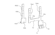
図7は、第1のピン接触片70及び第2のピン接触片60Aの斜視図である。図8は、第3のピン接触片60Bの斜視図である。
第1のピン接触片70は、第1のピン受け部72aと、第2のピン受け部72bと、接続部73と、速結端子部71とを有し、これらが、たとえば一体的に形成されているものである。第1のピン受け部72aは、蓋体50のスリット52を通過して第1の空間S1に設けられ、第1の直管形照明ランプ20Aが第1の筐体31aに取り付けられたときに第1の直管形照明ランプ20Aのランプピン23と接触するものである。第1のピン受け部72aは、一端側が接続部73の一端側に接続され、接続部73との接続位置から第1の回転子40a側に延びるように形成された板状部材である。第2のピン受け部72bは、蓋体50のスリット52は通過せず、第2の空間S2に設けられ、第2の直管形照明ランプ20Bが第2の筐体31bに取り付けられたときに第2の直管形照明ランプ20Bのランプピン23と接触するものである。第2のピン受け部72bは、一端側が接続部73の他端側に接続され、接続部73との接続位置から第2の回転子40b側に延びるように形成された板状部材である。
FIG. 7 is a perspective view of the first
The first
接続部73は、蓋体50のスリット52を通って第1の空間S1及び第2の空間S2に跨がるように設けられ、第1のピン受け部72aと第2のピン受け部72bとを接続するものである。接続部73は、第1の空間S1側から第2の空間S2側に向かう方向に延びるように形成された板状部材である。
速結端子部71は、上述した電線挿入孔を通る電線に接続されるものである。速結端子部71は、たとえば第2の筐体31bに支持されるものである。なお、第2の筐体31bに支持される構造ではなく、蓋体50に支持される構造であってもよい。
The connecting
The quick
第2のピン接触片60Aは、ピン受け部62Aが第1のピン受け部72aと対をなすように、第1の空間S1の第1のピン受け部72aの対向位置に設けられるものである。すなわち、第2のピン接触片60Aは、第1の空間S1に設けられ、第1の直管形照明ランプ20Aが第1の筐体31aに取り付けられたときに、第1の直管形照明ランプ20Aのランプピン23とピン受け部62Aで接触するものである。第2のピン接触片60Aは、一端側に速結端子部61Aが形成され、他端側にピン受け部62Aが形成されている。ピン受け部62Aは、第1のピン受け部72aと同様の形状を有する板状部材である。
The second
第3のピン接触片60Bは、第2のピン接触片60Aと同様の形状を有しているものである。そして、第3のピン接触片60Bは、ピン受け部62Bが第2のピン受け部72bと対をなすように、第2の空間S2の第2のピン受け部72bの対向位置に設けられるものである。第3のピン接触片60Bは、第2の空間S2に設けられ、第2の直管形照明ランプ20Bが第2の筐体31bに取り付けられたときに、第2の直管形照明ランプ20Bのランプピン23とピン受け部62Bで接触するものである。第3のピン接触片60Bは、一端側に速結端子部61Bが形成され、他端側にピン受け部62Bが形成されている。ピン受け部62Bは、第2のピン受け部72bと同様の形状を有する板状部材である。
The third
第1のピン受け部72a及びピン受け部62Aは、ランプピン23の軸部23aに接触するものであって、第1の空間S1側から第2の空間S2側に向かう方向の幅が軸部23aの長さよりも短く形成されている。そして、第1のピン受け部72a及びピン受け部62Aは、ピン受け部62Aが延びる方向における中央部分に軸部23aが嵌り込む段差部72a1及び段差部62A1が形成されている。このように、段差部72a1及び段差部62A1が形成されていることにより、ランプピン23と第1のピン受け部72a及びピン受け部62Aとの接続信頼性を向上させることができる。
The first
第2のピン受け部72b及びピン受け部62Bについても同様である。すなわち、第2のピン受け部72b及びピン受け部62Bは、ランプピン23の軸部23aに接触するものであって、第1の空間S1側から第2の空間S2側に向かう方向の幅が軸部23aの長さよりも短く形成されている。そして、第2のピン受け部72b及びピン受け部62Bは、ピン受け部62Bが延びる方向における中央部分に軸部23aが嵌り込む段差部72b1及び段差部62B1が形成されている。このように、段差部72b1及び段差部62B1が形成されていることにより、ランプピン23と第2のピン受け部72b及びピン受け部62Bとの接続信頼性を向上させることができる。
The same applies to the second
図9は、本実施の形態に係る第2のソケット80の分解斜視図である。第2のソケット80は、第1の直管形照明ランプ20A及び第2の直管形照明ランプ20Bのうちの第1のソケット30に取り付けられていない側の第2の口金21bが取り付けられるものである。図9に示すように、第2のソケット80は、筐体31cと、回転子40cと、2つのピン接触片60Cと、蓋体81とを有しているものである。
FIG. 9 is an exploded perspective view of the
筐体31cは、第1のソケット30の第1の筐体31a及び第2の筐体31bと同様の形状を有するものである。そして、筐体31cは、蓋体81に着脱自在に取り付けられるものである。また、回転子40cは、第1のソケット30の第1の回転子40a及び第2の回転子40bと同様の形状を有するものである。さらに、ピン接触片60Cは、第2のピン接触片60A及び第3のピン接触片60Bと同様の形状を有するものである。
このように、第2のソケット80は、第1のソケット30の大部分の部品を流用することで製造することができるようになっている。すなわち、第2のソケット80は、第1のソケット30の第1の筐体31a(又は第2の筐体31b)、第1の回転子40a(又は第2の回転子40b)、及び第2のピン接触片60A(又は第3のピン接触片60B)を流用することで製造することができる。なお、図9に示す開口部T3は、第1の開口部T1(又は第2の開口部T2)に対応する。
The
Thus, the
なお、第2のソケット80は、蓋体81については第1のソケット30の蓋体50とは形状が異なっている。ただし、蓋体81は、蓋体50の一方側の面、或いは他方側の面と同様の形状を有しているので、蓋体50とは形状が異なるものの、設計は容易なものとなっている。
The
[本実施の形態に係る第1のソケット30及び第2のソケット80の有する効果]
本実施の形態に係る第1のソケット30は、第1の筐体31a、第2の筐体31b及び蓋体50で外郭が構成されるものである。たとえば、第2のピン接触片60A及び第1の回転子40aが収容されるように、第1の筐体31aと蓋体50とを嵌合する。そして、スリット52を介して接続部73の一部及び第1のピン受け部72aを第1の空間S1側に配置した状態において、接続部73の他方、第2のピン受け部72b、第3のピン接触片60B及び第2の回転子40bが収容されるように、第2の筐体31bと蓋体50とを嵌合する。この組立方法は一例ではあるが、このように各部材を嵌合させることで第1のソケット30を組み立てることができる。
そして、実施の形態1に係る第1のソケット30では、特許文献1のような連結部品を設けなくても、2つの直管形照明ランプを直列に並ぶように配置することができるものである。このため、連結部品が不要となる分、第1のソケット30が取り付けられる照明装置10の長手方向の大型化を抑制することができる。
[Effects of the
In the
And in the
本実施の形態に係る第1のソケット30は、照明装置10の長手方向の大型化を抑制することができるため、意匠性を向上させることもできる。
Since the
本実施の形態に係る第1のソケット30は、特許文献1のような連結部品を設けなくてもよく、その分、第1の直管形照明ランプ20Aと第2の直管形照明ランプ20Bとを近づけることができる。これにより、第1の直管形照明ランプ20Aの発光面と第2の直管形照明ランプ20Bの発光面との間隔を近づけることができ、光ムラが生じてしまうことを抑制することができる。
The
本実施の形態に係る第1のソケット30は、特許文献1のような連結部品、及び2つのソケットを照明装置10に取り付ける作業の分だけ、照明装置10に組み付ける作業の時間の抑制を図ることができる。これにより、照明装置10の製造コストを抑制することができる。
The
本実施の形態に係る第1のソケット30は、第1のソケット30を構成する部材を流用することで第2のソケット80を製造することができるものである。すなわち、第2のソケット80は、第1のソケット30の第1の筐体31a(又は第2の筐体31b)、第1の回転子40a(又は第2の回転子40b)、及び第2のピン接触片60A(又は第3のピン接触片60B)を流用することで製造することができる。このように、第1のソケット30は、第2のソケット80と、大部分の部材が共用可能となっており、その分、製造コストを抑制することができる。なお、大部分の部材が共用可能であるため、第2のソケット80について、第1のソケット30とは別の構造の設計を行う負担が抑制され、開発コストも抑制することができる。
The
なお、第2のソケット80の蓋体81は、第1のソケット30の蓋体50とは形状が異なっている。
しかし、たとえば蓋体50の一方の面の嵌合部54及び爪部55などを折ることで、蓋体50で蓋体81を流用することができる。これにより、蓋体81についての金型を作成する必要がなく、その分、製造コストを抑制することができる。
また、嵌合部54及び爪部55などを折って流用しない場合であっても、蓋体81は、蓋体50の一方側の面、或いは他方側の面と同様の形状を有しているので、蓋体50とは形状が異なるものの、設計は容易なものとなっており、開発コストを抑制することができるものである。
The
However, the
Further, even when the
本実施の形態に係る第1のソケット30は、第1のピン接触片70を有しているものであり、1つの接触片で2つの直管形照明ランプ20A、20Bに電気的に接続されるように構成されている。このため、第1のソケット30に接続する電線の数を減らすことができるため、その分、接続不良を削減し、品質の向上を図ることができる。
The
3 反射板、10 照明装置、11 器具本体、13 ランプピン、15 凸部、20A 第1の直管形照明ランプ、20B 第2の直管形照明ランプ、20a 発光管、21a 第1の口金、21b 第2の口金、23 ランプピン、23a 軸部、23b 抜け止め部、30 第1のソケット、31a 第1の筐体、31b 第2の筐体、31c 筐体、32 第1の開口部、33 嵌合受部、34a 器具取付部、34b 器具取付部、40a 第1の回転子、40b 第2の回転子、40c 回転子、42a 切欠部、42b 切欠部、45a 接触面、45b 接触面、46a 凹部、46b 凹部、50 蓋体、51 爪部、52 スリット、53 回転保持部、54 嵌合部、55 爪部、60 ピン接続部、60A 第2のピン接触片、60B 第3のピン接触片、60C ピン接触片、61A 速結端子部、61B 速結端子部、62A ピン受け部、62A1 段差部、62B ピン受け部、62B1 段差部、70 第1のピン接触片、71 速結端子部、72a 第1のピン受け部、72a1 段差部、72b 第2のピン受け部、72b1 段差部、73 接続部、80 第2のソケット、81 蓋体、S1 第1の空間、S2 第2の空間、T1 第1の開口部、T2 第2の開口部、T3 開口部。 DESCRIPTION OF SYMBOLS 3 Reflector, 10 Illuminating device, 11 Apparatus body, 13 Lamp pin, 15 Convex part, 20A 1st straight tube | pipe type illumination lamp, 20B 2nd straight tube | pipe type illumination lamp, 20a Light emission tube, 21a 1st nozzle | cap | die, 21b 2nd base, 23 Lamp pin, 23a Shaft part, 23b Retaining prevention part, 30 1st socket, 31a 1st housing | casing, 31b 2nd housing | casing, 31c housing | casing, 32 1st opening part, 33 fitting Joint part, 34a Instrument mounting part, 34b Instrument mounting part, 40a First rotor, 40b Second rotor, 40c Rotor, 42a Notch part, 42b Notch part, 45a Contact surface, 45b Contact surface, 46a Concave part 46b Recess, 50 Lid, 51 Claw part, 52 Slit, 53 Rotation holding part, 54 Fitting part, 55 Claw part, 60 Pin connection part, 60A Second pin contact piece, 60B Third Contact piece, 60C pin contact piece, 61A fast connection terminal portion, 61B fast connection terminal portion, 62A pin receiving portion, 62A1 step portion, 62B pin receiving portion, 62B1 step portion, 70 first pin contact piece, 71 fast connection Terminal portion, 72a first pin receiving portion, 72a1 stepped portion, 72b second pin receiving portion, 72b1 stepped portion, 73 connecting portion, 80 second socket, 81 lid, S1 first space, S2 second Space, T1 first opening, T2 second opening, T3 opening.
Claims (6)
第1の開口部及び第1の空間を有し、第1の直管形照明ランプの前記口金側が取り付けられる第1の筐体と
第2の開口部及び第2の空間を有し、第2の直管形照明ランプの前記口金側が取り付けられる第2の筐体と、
前記第1の筐体の前記第1の空間及び前記第2の筐体の前記第2の空間にそれぞれ設けられ、前記ランプピンに電気的に接続される複数のピン接触片と、
前記第1の筐体の前記第1の開口部と前記第2の筐体の前記第2の開口部とに着脱自在に設けられ、前記第1の空間と前記第2の空間とを仕切る蓋体と、
を有する
ことを特徴とするソケット。 A socket to which a straight tube-shaped illumination lamp having a long arc tube and a base attached to an end of the arc tube and provided with a lamp pin is attached,
A first housing having a first opening and a first space, to which the base side of the first straight tube illumination lamp is attached; a second opening and a second space; A second housing to which the base side of the straight tube illumination lamp is attached;
A plurality of pin contact pieces provided respectively in the first space of the first housing and the second space of the second housing and electrically connected to the lamp pins;
A lid that is detachably provided in the first opening of the first casing and the second opening of the second casing, and partitions the first space and the second space. Body,
Socket characterized by having.
前記第1の空間と前記第2の空間とを連通するスリットが形成され、
前記複数のピン接触片のうちの一つである第1のピン接触片は、
前記第1の空間に設けられ、前記第1の直管形照明ランプが前記第1の筐体に取り付けられたときに前記第1の直管形照明ランプの前記ランプピンと接触する第1のピン受け部と、
前記第2の空間に設けられ、前記第2の直管形照明ランプが前記第2の筐体に取り付けられたときに前記第2の直管形照明ランプの前記ランプピンと接触する第2のピン受け部と、
前記スリットを通って前記第1の空間及び前記第2の空間に跨がるように設けられ、前記第1のピン受け部と前記第2のピン受け部とを接続する接続部とを有する
ことを特徴とする請求項1に記載のソケット。 In the lid,
A slit is formed to communicate the first space and the second space;
The first pin contact piece, which is one of the plurality of pin contact pieces,
A first pin provided in the first space and in contact with the lamp pin of the first straight tube illumination lamp when the first straight tube illumination lamp is attached to the first housing. A receiver,
A second pin provided in the second space and in contact with the lamp pin of the second straight tube illumination lamp when the second straight tube illumination lamp is attached to the second housing. A receiver,
A connecting portion that is provided so as to straddle the first space and the second space through the slit and connects the first pin receiving portion and the second pin receiving portion; The socket according to claim 1.
前記第1のピン受け部と対をなすように、前記第1の空間の前記第1のピン受け部の対向位置に設けられ、
前記複数のピン接触片のうちの一つである第3のピン接触片は、
前記第2のピン受け部と対をなすように、前記第2の空間の前記第2のピン受け部の対向位置に設けられた
ことを特徴とする請求項2に記載のソケット。 The second pin contact piece, which is one of the plurality of pin contact pieces,
So as to be paired with the first pin receiving portion, provided at a position facing the first pin receiving portion in the first space;
A third pin contact piece that is one of the plurality of pin contact pieces,
The socket according to claim 2, wherein the socket is provided at a position facing the second pin receiving portion in the second space so as to form a pair with the second pin receiving portion.
第1の開口部と、
前記第1の開口部に回転自在に取り付けられ、前記第1の直管形照明ランプの前記ランプピンが挿入される凹部を有し、前記第1の直管形照明ランプの回転とともに前記第1の筐体に対し回転する第1の回転子とを有し、
前記第2の筐体は、
第2の開口部と、
前記第2の開口部に回転自在に取り付けられ、前記第2の直管形照明ランプの前記ランプピンが挿入される凹部を有し、前記第2の直管形照明ランプの回転とともに前記第2の筐体に対し回転する第2の回転子とを有する
ことを特徴とする請求項1〜3のいずれか一項に記載のソケット。 The first housing is
A first opening;
The first straight tube illumination lamp is rotatably attached to the first opening, and has a recess into which the lamp pin of the first straight tube illumination lamp is inserted. A first rotor that rotates relative to the housing;
The second housing is
A second opening;
The second straight tube illumination lamp has a recess that is rotatably attached to the second opening and into which the lamp pin of the second straight tube illumination lamp is inserted. It has a 2nd rotor rotated with respect to a housing | casing. The socket as described in any one of Claims 1-3 characterized by the above-mentioned.
前記第1のソケットが取り付けられた器具本体と、
前記第1のソケットを介して前記直管形照明ランプに電力を供給する電源装置と、
を備えた
ことを特徴とする照明器具。 The first socket according to any one of claims 1 to 4,
An instrument body to which the first socket is attached;
A power supply device for supplying power to the straight tube lamp via the first socket;
A lighting fixture characterized by comprising:
ことを特徴とする請求項3に従属する請求項4に従属する請求項5に記載の照明器具。 A first housing or a second housing of the first socket; a first rotor or a second rotor of the first socket; and a second of the first socket. The lighting apparatus according to claim 5, which is dependent on claim 4, dependent on claim 3, further comprising a second socket having a pin contact piece and a third pin contact piece.
Priority Applications (1)
| Application Number | Priority Date | Filing Date | Title |
|---|---|---|---|
| JP2014018635A JP6289133B2 (en) | 2014-02-03 | 2014-02-03 | Socket and lighting apparatus using the same |
Applications Claiming Priority (1)
| Application Number | Priority Date | Filing Date | Title |
|---|---|---|---|
| JP2014018635A JP6289133B2 (en) | 2014-02-03 | 2014-02-03 | Socket and lighting apparatus using the same |
Publications (2)
| Publication Number | Publication Date |
|---|---|
| JP2015146261A true JP2015146261A (en) | 2015-08-13 |
| JP6289133B2 JP6289133B2 (en) | 2018-03-07 |
Family
ID=53890416
Family Applications (1)
| Application Number | Title | Priority Date | Filing Date |
|---|---|---|---|
| JP2014018635A Active JP6289133B2 (en) | 2014-02-03 | 2014-02-03 | Socket and lighting apparatus using the same |
Country Status (1)
| Country | Link |
|---|---|
| JP (1) | JP6289133B2 (en) |
Citations (11)
| Publication number | Priority date | Publication date | Assignee | Title |
|---|---|---|---|---|
| DE1130073B (en) * | 1960-03-31 | 1962-05-24 | Siemens Ag | Light band made up of individual lights with an electrical coupling bridge |
| JPS5273970U (en) * | 1975-11-29 | 1977-06-02 | ||
| JPS56161723U (en) * | 1980-04-30 | 1981-12-02 | ||
| JPS5794170U (en) * | 1980-11-29 | 1982-06-10 | ||
| JPS57176091U (en) * | 1981-04-30 | 1982-11-06 | ||
| JPS618988U (en) * | 1984-06-22 | 1986-01-20 | 松下電工株式会社 | fluorescent light socket |
| JP2001512279A (en) * | 1997-07-28 | 2001-08-21 | ヒューレット・パッカード・カンパニー | Strip lighting device |
| JP2005050729A (en) * | 2003-07-30 | 2005-02-24 | Mitsubishi Electric Corp | Socket for straight tube lamp and lighting apparatus |
| JP2010129325A (en) * | 2008-11-27 | 2010-06-10 | Sea&Sea Sunpak Co Ltd | Led illumination lamp connector |
| JP2012221638A (en) * | 2011-04-06 | 2012-11-12 | Mitsubishi Electric Corp | Receptacle and luminaire |
| JP2013243125A (en) * | 2012-04-25 | 2013-12-05 | Mitsubishi Electric Corp | Lamp socket, illuminating fixture, and led illuminating device |
-
2014
- 2014-02-03 JP JP2014018635A patent/JP6289133B2/en active Active
Patent Citations (11)
| Publication number | Priority date | Publication date | Assignee | Title |
|---|---|---|---|---|
| DE1130073B (en) * | 1960-03-31 | 1962-05-24 | Siemens Ag | Light band made up of individual lights with an electrical coupling bridge |
| JPS5273970U (en) * | 1975-11-29 | 1977-06-02 | ||
| JPS56161723U (en) * | 1980-04-30 | 1981-12-02 | ||
| JPS5794170U (en) * | 1980-11-29 | 1982-06-10 | ||
| JPS57176091U (en) * | 1981-04-30 | 1982-11-06 | ||
| JPS618988U (en) * | 1984-06-22 | 1986-01-20 | 松下電工株式会社 | fluorescent light socket |
| JP2001512279A (en) * | 1997-07-28 | 2001-08-21 | ヒューレット・パッカード・カンパニー | Strip lighting device |
| JP2005050729A (en) * | 2003-07-30 | 2005-02-24 | Mitsubishi Electric Corp | Socket for straight tube lamp and lighting apparatus |
| JP2010129325A (en) * | 2008-11-27 | 2010-06-10 | Sea&Sea Sunpak Co Ltd | Led illumination lamp connector |
| JP2012221638A (en) * | 2011-04-06 | 2012-11-12 | Mitsubishi Electric Corp | Receptacle and luminaire |
| JP2013243125A (en) * | 2012-04-25 | 2013-12-05 | Mitsubishi Electric Corp | Lamp socket, illuminating fixture, and led illuminating device |
Also Published As
| Publication number | Publication date |
|---|---|
| JP6289133B2 (en) | 2018-03-07 |
Similar Documents
| Publication | Publication Date | Title |
|---|---|---|
| JP6180052B2 (en) | LED lamp | |
| TWI383551B (en) | Anschlusselement zur elektrischen anbindung einer led | |
| US8157408B2 (en) | Lighting apparatus | |
| JP5662065B2 (en) | Straight tube lamp and lighting device | |
| JP2012084323A (en) | Straight tube type lamp and lighting fixture | |
| JP5039166B2 (en) | Lighting device | |
| JP2010244872A (en) | Led lighting apparatus | |
| JP6289133B2 (en) | Socket and lighting apparatus using the same | |
| JP5660383B2 (en) | Straight tube lamp and luminaire | |
| JP2012221636A (en) | Lamp and lighting system | |
| JP6380760B2 (en) | Lighting device | |
| JP2016110955A (en) | Lighting device | |
| JP5736500B2 (en) | Straight tube lamp and lighting device | |
| JP2012104357A (en) | Lamp, lamp socket, and lighting fixture using them | |
| JP5769034B2 (en) | Socket and lighting device | |
| JP7279926B2 (en) | LED lighting equipment | |
| JP6465148B2 (en) | Straight tube lamp and luminaire | |
| JP5662788B2 (en) | lighting equipment | |
| CN101802489B (en) | A lamp having contact members at its surrounding edge, and a lamp holder | |
| JP2011171070A (en) | Illumination fixture | |
| JP5915912B2 (en) | Straight tube lamp and luminaire | |
| WO2012176592A1 (en) | Light bulb socket | |
| JP2008235215A (en) | Fluorescent lamp, socket, and luminaire | |
| JP6014374B2 (en) | LED lamp socket and lighting apparatus using the same | |
| JP6014375B2 (en) | LED lamp socket and lighting apparatus using the same |
Legal Events
| Date | Code | Title | Description |
|---|---|---|---|
| A621 | Written request for application examination |
Free format text: JAPANESE INTERMEDIATE CODE: A621 Effective date: 20170105 |
|
| A977 | Report on retrieval |
Free format text: JAPANESE INTERMEDIATE CODE: A971007 Effective date: 20170907 |
|
| A131 | Notification of reasons for refusal |
Free format text: JAPANESE INTERMEDIATE CODE: A131 Effective date: 20171017 |
|
| A521 | Request for written amendment filed |
Free format text: JAPANESE INTERMEDIATE CODE: A523 Effective date: 20171206 |
|
| TRDD | Decision of grant or rejection written | ||
| A01 | Written decision to grant a patent or to grant a registration (utility model) |
Free format text: JAPANESE INTERMEDIATE CODE: A01 Effective date: 20180109 |
|
| A61 | First payment of annual fees (during grant procedure) |
Free format text: JAPANESE INTERMEDIATE CODE: A61 Effective date: 20180206 |
|
| R150 | Certificate of patent or registration of utility model |
Ref document number: 6289133 Country of ref document: JP Free format text: JAPANESE INTERMEDIATE CODE: R150 |
|
| R250 | Receipt of annual fees |
Free format text: JAPANESE INTERMEDIATE CODE: R250 |
|
| R250 | Receipt of annual fees |
Free format text: JAPANESE INTERMEDIATE CODE: R250 |
|
| R250 | Receipt of annual fees |
Free format text: JAPANESE INTERMEDIATE CODE: R250 |
|
| R250 | Receipt of annual fees |
Free format text: JAPANESE INTERMEDIATE CODE: R250 |