JP2015137142A - Sheet conveying apparatus, image reading apparatus, and image forming apparatus - Google Patents
Sheet conveying apparatus, image reading apparatus, and image forming apparatus Download PDFInfo
- Publication number
- JP2015137142A JP2015137142A JP2014007699A JP2014007699A JP2015137142A JP 2015137142 A JP2015137142 A JP 2015137142A JP 2014007699 A JP2014007699 A JP 2014007699A JP 2014007699 A JP2014007699 A JP 2014007699A JP 2015137142 A JP2015137142 A JP 2015137142A
- Authority
- JP
- Japan
- Prior art keywords
- sheet
- sheet conveying
- guide member
- holes
- guide
- Prior art date
- Legal status (The legal status is an assumption and is not a legal conclusion. Google has not performed a legal analysis and makes no representation as to the accuracy of the status listed.)
- Granted
Links
Images


Landscapes
- Feeding Of Articles By Means Other Than Belts Or Rollers (AREA)
- Soundproofing, Sound Blocking, And Sound Damping (AREA)
Abstract
【課題】複数の種類のシートの振動放射音を低減することのできるシート搬送装置、画像読取装置及び画像形成装置を提供する。【解決手段】シート搬送路を構成し、搬送されるシートを案内するシートガイド13に複数の入射孔13dを設けると共に、シートガイド13のシートと当接する側と反対側に、シートガイド13に設けられた複数の入射孔13dとそれぞれ連通する複数の共鳴管19aを有するスライダ19を配置し、このスライダ19を移動させて複数の入射孔13dの複数の共鳴管19aに対する開口面積を変更する。【選択図】図3A sheet conveying apparatus, an image reading apparatus, and an image forming apparatus capable of reducing vibration radiation sound of a plurality of types of sheets are provided. SOLUTION: A plurality of incident holes 13d are provided in a sheet guide 13 that constitutes a sheet conveyance path and guides a conveyed sheet, and is provided in the sheet guide 13 on the opposite side of the sheet guide 13 from the side in contact with the sheet. A slider 19 having a plurality of resonance tubes 19a respectively communicating with the plurality of incident holes 13d is disposed, and the slider 19 is moved to change the opening areas of the plurality of incident holes 13d with respect to the plurality of resonance tubes 19a. [Selection] Figure 3
Description
本発明は、シート搬送装置、画像読取装置及び画像形成装置に関し、特に記録紙や原稿等のシートを搬送する際、シートの振動により発生する振動放射音を低減するための構成に関する。 The present invention relates to a sheet conveying apparatus, an image reading apparatus, and an image forming apparatus, and more particularly to a configuration for reducing vibration radiated sound generated by sheet vibration when conveying a sheet such as recording paper or a document.
従来、複写機、プリンタ、ファクシミリ等の画像形成装置や画像読取装置においては、画像形成部や画像読取部に記録紙や原稿等のシートを搬送するシート搬送装置を備えている。ところで、シート搬送装置により搬送されるシートがシート搬送路を通過する際、シート搬送路を構成するシートガイドから反力を受ける結果、シートが振動して振動放射音が発生する。この振動放射音の周波数は、シートの紙種(坪量)によって異なり、例えば80g/m2のA4サイズシートを搬送する際の振動放射音は8756Hz周辺の音を多く含み、180g/m2のA4サイズシートの場合は4378Hz周辺の音を多く含む。 2. Description of the Related Art Conventionally, image forming apparatuses such as copying machines, printers, facsimiles, and image reading apparatuses are provided with a sheet conveying device that conveys a sheet such as a recording sheet or a document to the image forming unit or the image reading unit. By the way, when a sheet conveyed by the sheet conveying apparatus passes through the sheet conveying path, as a result of receiving a reaction force from a sheet guide constituting the sheet conveying path, the sheet vibrates to generate vibration radiation sound. The frequency of the vibration radiated sound varies depending on the sheet type (basis weight) of the sheet. For example, the vibration radiated sound when conveying an A4 size sheet of 80 g / m 2 includes a lot of sound around 8756 Hz, and the frequency of 180 g / m 2 In the case of an A4 size sheet, it contains a lot of sounds around 4378 Hz.
シートの振動放射音は高周波の音を多く含んでいるため、耳障りであることから、従来は、例えば外装カバーをヘルムホルツ吸音管にして振動放射音を吸音し、画像形成装置外部へ放射させないようにしたものがある(特許文献1参照)。 Since the vibration radiated sound of the sheet contains a lot of high frequency sound, it is harsh, so conventionally, for example, the exterior cover is made a Helmholtz sound absorption tube to absorb the vibration radiated sound and not radiate it outside the image forming apparatus. (See Patent Document 1).
ここで、外装カバーをヘルムホルツ吸音管とした場合、ヘルムホルツ吸音管により低減させることのできるシートの振動放射音は入射孔や共鳴管の大きさ等により決定されるため、低減させることのできるシートの振動放射音は限られる。しかし、既述したように、従来のシート搬送装置は、異なる種類のシートを搬送することから、搬送するシートの種類により異なる周波数の振動放射音が発生する。 Here, when the exterior cover is a Helmholtz sound-absorbing tube, the vibration radiation sound of the sheet that can be reduced by the Helmholtz sound-absorbing tube is determined by the size of the incident hole and the resonance tube, etc. Vibrating radiated sound is limited. However, as described above, since the conventional sheet conveying apparatus conveys different types of sheets, vibration radiation sound having different frequencies is generated depending on the type of the sheet to be conveyed.
このため、外装カバーをヘルムホルツ吸音管とした場合、所定の種類のシートについては効果的に振動放射音を低減することができるが、他の種類のシートに関しては振動放射音を低減することができない。つまり、搬送するシートの種類が多い場合には、振動放射音を低減することができない。 For this reason, when the exterior cover is a Helmholtz sound absorption tube, vibration radiation sound can be effectively reduced for a predetermined type of sheet, but vibration radiation sound cannot be reduced for other types of sheets. . That is, when there are many types of sheets to be conveyed, vibration radiated sound cannot be reduced.
そこで、本発明は、このような現状に鑑みてなされたものであり、複数の種類のシートの振動放射音を低減することのできるシート搬送装置、画像読取装置及び画像形成装置を提供することを目的とするものである。 Accordingly, the present invention has been made in view of such a current situation, and provides a sheet conveying apparatus, an image reading apparatus, and an image forming apparatus capable of reducing vibration radiation sound of a plurality of types of sheets. It is the purpose.
本発明は、シート搬送装置において、シートが通過するシート搬送路と、前記シート搬送路を通過するシートの振動による振動放射音を吸音する吸音手段と、を備え、前記吸音手段は、前記シート搬送路を構成し、搬送されるシートを案内すると共に、複数の孔が形成されたガイド部材と、前記ガイド部材のシートと当接する側と反対側に配置され、前記複数の孔とそれぞれ連通する複数の空間を有するベース部材と、を備え、前記複数の孔の前記複数の空間に対する開口面積を変更するよう前記ガイド部材及び前記ベース部材の少なくとも一方を移動可能とすることを特徴とするものである。 The present invention provides a sheet conveying apparatus, comprising: a sheet conveying path through which a sheet passes; and a sound absorbing means for absorbing vibration radiation sound caused by vibration of the sheet passing through the sheet conveying path, wherein the sound absorbing means includes the sheet conveying path. A guide member that forms a path and guides a sheet to be conveyed, and a plurality of holes that are formed on a side opposite to the side of the guide member that abuts against the sheet and communicates with the plurality of holes. And a base member having a space of at least one of the guide member and the base member to be movable so as to change an opening area of the plurality of holes with respect to the plurality of spaces. .
また本発明は、シート搬送装置において、シートが通過するシート搬送路と、前記シート搬送路を通過するシートの振動による振動放射音を吸音する吸音手段と、を備え、前記吸音手段は、前記シート搬送路を構成し、搬送されるシートを案内すると共に、複数の孔が形成されたガイド部材と、前記ガイド部材のシートと当接する側と反対側に配置され、前記複数の孔とそれぞれ連通する複数の空間を有し、前記複数の孔の前記複数の空間に対する開口面積を変更するよう前記ガイド部材に沿って移動可能な変更手段と、を有することを特徴とするものである。 In the sheet conveying apparatus, the present invention further includes: a sheet conveying path through which the sheet passes; and a sound absorbing means for absorbing vibration radiation sound caused by vibration of the sheet passing through the sheet conveying path, wherein the sound absorbing means includes the sheet A conveyance path is configured to guide the conveyed sheet, and a guide member having a plurality of holes is disposed on a side opposite to the side of the guide member that contacts the sheet, and communicates with each of the plurality of holes. It has a change means which has a plurality of spaces and is movable along the guide member so as to change the opening area of the plurality of holes with respect to the plurality of spaces.
本発明のように、ガイド部材に設けられた複数の孔とそれぞれ連通する複数の空間を有する変更手段を移動させ、複数の孔の複数の空間に対する開口面積を変更することにより、複数の種類のシートの振動放射音を低減することができる。 As in the present invention, by moving the changing means having a plurality of spaces respectively communicating with the plurality of holes provided in the guide member and changing the opening area of the plurality of holes with respect to the plurality of spaces, The vibration radiation sound of the sheet can be reduced.
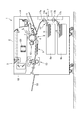
以下、本発明を実施するための形態について図面を用いて詳細に説明する。図1は、本発明の第1の実施の形態に係るシート搬送装置を備えた画像形成装置の構成を示す図である。図1において、1は画像形成装置であり、この画像形成装置1は、画像形成装置本体1Aと、画像形成装置本体上部に設けられ、原稿画像を読み取る画像読取装置1Bを備えている。
Hereinafter, embodiments for carrying out the present invention will be described in detail with reference to the drawings. FIG. 1 is a diagram illustrating a configuration of an image forming apparatus including a sheet conveying device according to a first embodiment of the present invention. In FIG. 1,
また、画像形成装置本体1Aの下部には給紙カセット6a,6bに収納されたシートSを給送するシート給送装置1Cが設けられている。シート給送装置1Cのシート給送方向下流には、搬送ローラ17a,17b及び搬送ローラ17a,17bに当接する搬送コロ15a,15bを備えたシート搬送装置7が設けられている。また、シート給送装置1Cの上方には矢印方向に回転自在な像担持体である感光体ドラム4等を有し、シートSに画像を形成する画像形成部1Dが設けられている。
A sheet feeding device 1C that feeds the sheets S stored in the
画像読取装置1Bには、圧板2により不図示のプラテンガラス上にセットされた不図示の原稿画像を読み取る画像読取部であるスキャナユニット3が設けられている。そして、原稿画像を読み取る場合には、プラテンガラス上にセットされた不図示の原稿に光を照射しながらスキャナユニット3を移動させる。このように光を照射しながらスキャナユニット3が移動すると、原稿からの反射光がレンズ109等を介して矢印方向に回転している感光体ドラム4の外周面に結像される。ここで、感光体ドラム4は、表面が一様に帯電されており、このように表面が帯電されている感光体ドラム4に光を照射することにより、感光体ドラム表面上には、走査された光に応じた静電潜像が形成される。この後、この感光体ドラム上の静電潜像は、トナーによってトナー像として可視像化される。
The
一方、このようなトナー像形成動作に並行してシート給送装置1Cにより、給紙カセット6a,6bに収納されたシートSが送り出される。そして、上部の給紙カセット6aから送り出されたシートSは、シート搬送路Rに設けられた上部搬送ローラ17a及び上部搬送コロ15aにより挟持されながら転写部8に搬送される。また、下部の給紙カセット6bから送り出されたシートSは、下部搬送ローラ17b及び下部搬送コロ15bにより上部搬送ローラ17a及び上部搬送コロ15aに搬送され、この後、上部搬送ローラ17a及び上部搬送コロ15aにより転写部8に搬送される。
On the other hand, in parallel with such a toner image forming operation, the sheet S stored in the
感光体ドラム4に形成されたトナー像は、転写部8において、搬送されたシート上に転写される。次に、トナー像の転写が終了すると、トナー像が転写されたシートSは搬送ベルト9によって定着部10まで搬送され、定着部10において加熱及び加圧されることによりトナー像がシートSの表面に定着される。この後、シートSは画像形成装置本体外の排紙トレイ50上に排出される。
The toner image formed on the photosensitive drum 4 is transferred onto the conveyed sheet in the transfer unit 8. Next, when the transfer of the toner image is completed, the sheet S to which the toner image has been transferred is conveyed to the
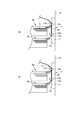
ところで、図1において、11はシート搬送装置本体を兼ねる画像形成装置本体1Aの側面に開閉自在に設けられたABS等の樹脂で形成されたカバー部材である外カバーである。この外カバー11は、シートがジャムした場合等に開放され、これによりシート搬送路Rが開放される。この外カバー11の上面及び下面の、シート搬送方向と直交する幅方向の一端には、図2に示すようにSUSなどの金属で形成されたピン12が固定されている。そして、このピン12を介して外カバー11は画像形成装置本体1Aの側面に開閉自在に支持される。
In FIG. 1,
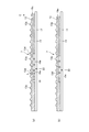
外カバー11の内壁面には、搬送されるシートSをガイド(案内)するガイド部材であるABS等の樹脂で形成されたシートガイド13が設けられている。このシートガイド13の表面には断面の半径が2mm、高さが2mmの半円状のリブ13aが、シートSのサイズに対応できるようにシート搬送方向に沿って複数突設されている。そして、複数のリブ13aを突設することにより、シート搬送時におけるシート搬送抵抗を軽減させている。また、リブ13aの間にシートSから出てくる紙粉を溜めることができるので、紙粉による搬送抵抗の増加も防ぐことができる。
On the inner wall surface of the
また、シートガイド13には4箇所ザグリ穴13bが形成されており、このザグリ穴13bに不図示のネジを取り付け、外カバー11に設けられた不図示のネジ穴にネジを取り付け、締めることによって、シートガイド13は外カバー11に固定される。なお、シートガイド13を固定した際、ネジの頭はザグリ穴13bに隠れるようになっているため、ネジがシートガイド13の表面に出ない。
The
シートガイド13の幅方向の他端の上部及び下部にはマグネット14が取り付けられている。そして、このマグネット14を、画像形成装置本体1Aの内部に設けられた不図示の金属板に磁力によって吸着させることにより、外カバー11は閉じられた状態で保持される。なお、外カバー11を開放する際は、外カバー11の外側に取り付けられた不図示のレバーを操作する。
このシートガイド13のシートSの幅方向中心(図中1点鎖線)に対して、左右対称に、既述した図1に示す、EPDMゴムで形成された円柱状の搬送ローラ17a,17bに当接する搬送コロ15a,15bが4箇所配置されている。この搬送コロ15a,15bはPOM樹脂で形成されており、シートSの最小幅サイズ(図中2点鎖線)に対して内側に配置することによって、シートSの全サイズに対して搬送できるように構成している。
With respect to the center of the sheet S in the width direction of the sheet S (one-dot chain line in the figure), the
また、搬送コロ15a,15bはPOM樹脂で形成された軸受16に、回転可能に支持されている。軸受16にはスリット16aが設けられており、このスリット16aにシートガイド13に突設されたアーム13cが入り込むように構成されている。これにより、軸受16はシートガイド13に対して、図中矢印B方向に平行移動可能となっている。
Further, the
アーム13cと軸受16との間には、軸受16を矢印B方向に付勢する不図示のバネが設けられる。なお、バネにより軸受16がアーム13cから外れないようにするため、軸受16には不図示のストッパが配置されている。そして、外カバー11を開放している時、軸受16はバネにより付勢されて矢印B方向に突出した状態でストッパによって保持される。
A spring (not shown) that urges the bearing 16 in the direction of arrow B is provided between the
また、外カバー11を閉めると、搬送コロ15a,15bは、搬送ローラ17a,17bに当接して矢印Bと反対方向に移動し、不図示のバネによる付勢力を受けて所定の圧力で搬送ローラ17a,17bに圧接する。なお、この状態で搬送ローラ17a,17bが不図示の搬送モータにより駆動されると、シートSは搬送ローラ17a,17bと搬送コロ15a,15bによって挟持搬送される。
When the
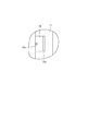
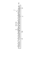
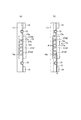
ところで、シートガイド13には、幅方向中央部に位置するリブ13aの間に、円形の孔である入射孔13dが、幅方向に4箇所、シート搬送方向に5箇所、合計20箇所形成されている。この20個の入射孔13dは、それぞれ図2のA−A断面図である図3に示すように直径が2mm、深さが5mm、断面積が10mm2のものである。
By the way, the
また、シートガイド13と外カバー11の間には隙間18が設けられ、この隙間18にはPOM樹脂で形成されたベース部材であるスライダ19が摺動可能に設けられている。そして、シートガイド13のシートと当接する側と反対側に配置されたスライダ19は、シートガイド13に形成された複数の入射孔13dとそれぞれ連通する空間である円柱状の共鳴管(共鳴空間)19aを有している。以下、この入射孔13dと、共鳴管19aを総称してヘルムホルツ吸音管22という。つまり、本実施の形態において、外カバー11には、シート搬送路Rを通過するシートの振動による振動放射音を吸音するための吸音手段であるヘルムホルツ吸音管22が取り付けられている。
A
なお、スライダ19の端部には操作部19cが設けられており、ユーザーもしくはサービスマンは、使用するシートSの種類(坪量)によって操作部19cを操作してスライダ19の位置を移動させる。また、本実施の形態において、スライダ19とシートガイド13と外カバー11の間には、スライダ19がスムーズに移動できるように潤滑材が設けられている。
An
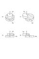
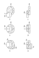
次に、ヘルムホルツ吸音管22の吸音原理と吸音周波数について図4を用いて説明する。図4の(a)はヘルムホルツ吸音管の斜視図、(b)はその中心断面図である。図4の(a)に示す入射孔13dに音が入射すると、入射孔13dの空気が質量となり、共鳴管19a内に閉じ込められた空気がバネとなり、所定の周波数をもって共振する。この時、入射孔13dの内周面と、入射孔13d内部の空気との間に摩擦が生じ、この摩擦によるエネルギー損失によって音の振動が減衰する。
Next, the sound absorption principle and sound absorption frequency of the Helmholtz
今、入射孔13dの断面積をS、深さ(長さ)をL、共鳴管19aの体積をV、入射孔13dの質量の変位をωとすると、共鳴管19a内部の体積変化率ΔはΔ=ωS/Vとなる。これに体積弾性率Kを掛けると、音が入射することによって生じる空気の圧力変化はKΔとなるため、空気の復元力はKSΔとなる。したがって、入射孔13dの質量に関する運動方程式は空気密度をρとすると、下記の式(1)となる。
ρSL(dω2/dt2)=−KSΔ・・(1)
Assuming that the cross-sectional area of the
ρSL (dω 2 / dt 2 ) = − KSΔ ·· (1)
音速をcとし、この式(1)をK=ρc2を用いて書き直すと、下記の式(2)となる。
(dω2/dt2)+(c2S/LV)ω=0・・(2)
When the speed of sound is c and this equation (1) is rewritten using K = ρc 2 , the following equation (2) is obtained.
(Dω 2 / dt 2 ) + (c 2 S / LV) ω = 0 ·· (2)
この式(2)から固有角周波数を求め周波数の単位に表すと、ヘルムホルツ吸音管22による吸音が可能な固有周波数fは、下記の式(3)となる。
f=c/2π(S/LV)1/2・・・(3)
When the natural angular frequency is obtained from this equation (2) and expressed in frequency units, the natural frequency f that can be absorbed by the Helmholtz
f = c / 2π (S / LV) 1/2 (3)
次に、本実施の形態におけるヘルムホルツ吸音管の固有周波数fを算出する(単位はSI単位系)。22℃において、音速cは344.76(m/s)である。入射孔13dの直径を2E−3(m)、深さLを5E−3(m)、断面積Sを10E−6(m2)とする。また、共鳴管19aは、底辺直径が5E−3(m)、高さが5E−3(m)の円柱で形成されているとすると、共鳴管19aの体積Vは78.54E−9(m3)となる。この数値を式(3)に代入すると、固有周波数fは次のようになる。
f=344.76/2π[10E−6×/(5E−3×78.54E−9)]1/2
=8756(Hz)
Next, the natural frequency f of the Helmholtz sound absorbing tube in the present embodiment is calculated (unit is SI unit system). At 22 ° C., the sound speed c is 344.76 (m / s). The diameter of the
f = 344.76 / 2π [10E-6 × / (5E-3 × 78.54E-9)] 1/2
= 8756 (Hz)
つまり、本実施の形態のヘルムホルツ吸音管22は、8756Hzの固有周波数をもち、この周波数近傍の音を低減させる効果を持つ。
In other words, the Helmholtz
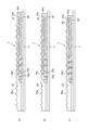
ところで、スライダ19は、既述した図3の(a)及び(b)に示す位置に移動可能となっており、本実施の形態では、シート搬送装置7により搬送されるシートSの種類(坪量)によってスライダ19の位置を変更する。なお、図3の(a)は、スライダ19を所定量引き出したときの状態を示しており、図3の(b)は、スライダ19を押し込んでシートガイド13に突き当てたときの状態を示している。
By the way, the
既述した図4の(a)及び(b)は、スライダ19が図3の(a)に示す位置にあるときのヘルムホルツ吸音管の状態を示しており、スライダ19が図3の(b)の位置にあるときには、ヘルムホルツ吸音管は、図4の(c)と(d)に示す状態になる。なお、スライダ19には、図5に示すように刻印19bが施されており、図3の(a)に示す位置にスライダ19を引き出す際、この刻印19bによりスライダ19を正確な位置に引き出すことができる。
4A and 4B described above show the state of the Helmholtz sound absorption tube when the
ここで、スライダ19が図3の(b)の位置にある場合、入射孔13dの共鳴管19aに臨む開口面積が小さくなり、これに伴い断面積Sが2.5E−6(m2)となるのでヘルムホルツ吸音管の固有周波数fは、既述した式(3)により次のようになる。
f=344.76/2π[2.5E−6×/(5E−3×78.54E−9)]1/2
=4378(Hz)
Here, when the
f = 344.76 / 2π [2.5E-6 × / (5E-3 × 78.54E-9)] 1/2
= 4378 (Hz)
このように、スライダ19が図3の(a)の位置にある場合のヘルムホルツ吸音管の固有周波数が8756(Hz)となるのに対し、スライダ19が図3の(b)の位置にある場合は、ヘルムホルツ吸音管の固有周波数は4378(Hz)となる。つまり、変更手段であるスライダ19の位置を変更することによって入射孔13dの共鳴管19aに臨む開口面積を変更することにより、ヘルムホルツ吸音管の固有周波数を変更することができる。
Thus, the natural frequency of the Helmholtz sound absorption tube when the
図6の(a)は、上部の給紙カセット6aに収納されたシートSが搬送される状態を示しており、上部の給紙カセット6aから送り出されたシートSはシート搬送装置7の上部搬送ローラ17aと、上部搬送コロ15aによって挟持搬送される。この時、シートSはシートガイド20に所定の圧力をもって摺擦しながら搬送するので、シートSは振動して振動放射音が発生する。
6A shows a state in which the sheet S stored in the upper
このとき、シートSが80g/m2のA4サイズのシートの場合、発明者の検討により、振動放射音は8756Hz近傍の周波数に大きなピークを持つことがわかっている。したがって、このような坪量を有するシートを使用する場合は、スライダ19を図3の(a)に示す位置に移動させる。これにより、8756Hz近傍の周波数の振動放射音が入射孔13dに入り込むと、既述したヘルムホルツ吸音管22の吸音原理により、振動放射音は減衰されて画像形成装置本体1A外部に放射される。
At this time, in the case where the sheet S is an A4 size sheet of 80 g / m 2 , it has been found by the inventor's investigation that the vibration radiated sound has a large peak at a frequency near 8756 Hz. Therefore, when using a sheet having such a basis weight, the
また、シートSが180g/m2のA4サイズのシートの場合、4378Hz近傍の周波数に大きなピークを持つことがわかっている。したがって、このような坪量を有するシートを使用する場合は、スライダ19を図3の(b)に示す位置に移動させる。これにより、4378Hz近傍の周波数の振動放射音が入射孔13dに入り込むと、振動放射音は減衰されて画像形成装置本体1A外部に放射される。このように、シートSが180g/m2のA4サイズのシートの場合は、スライダ19を移動してヘルムホルツ吸音管22の吸音周波数を変えることにより、4378Hz近傍の音を効果的に吸音することができる。
Further, it is known that when the sheet S is an A4 size sheet of 180 g / m 2 , it has a large peak at a frequency near 4378 Hz. Therefore, when using a sheet having such a basis weight, the
図6の(b)は下部の給紙カセット6bに収納されたシートSが搬送される状態を示している。下部の給紙カセット6bから送り出されたシートSはシート搬送装置7の下部搬送ローラ17bと下部搬送コロ15bによって挟持搬送された後、上部搬送ローラ17aと上部搬送コロ15aによって挟持搬送される。この際、シートSはシートガイド13のリブ13aによって反力を受け、振動放射音が発生する。この場合も、既述したようにスライダ19を移動させることにより、シートSの振動放射音を吸音することができる。
FIG. 6B shows a state in which the sheet S stored in the lower
以上説明したように、本実施の形態においては、シートガイド13に設けられた入射孔13dと共にヘルムホルツ吸音管22を構成する複数の共鳴管19aを有するスライダ19を移動可能に設けている。そして、シートの坪量に応じてスライダ19を移動させ、複数の入射孔13dの複数の共鳴管19aに対する開口面積を変更することにより、複数の種類のシートの振動放射音を低減することができる。
As described above, in the present embodiment, the
この結果、画像形成装置1の小型化等によりシート搬送装置7が外カバー11の近くである画像形成装置本体1Aの外側近くに配置されている場合でも、効果的にシートの振動放射音を低減させることができる。また、比較的振動放射音が発生し易い再生紙などのシートを使用してもシートの音を低減することができるので、リサイクル等の環境対応も可能になる。
As a result, even when the
次に、本発明の第2の実施の形態について説明する。図7は、本実施の形態に係るシート搬送装置7の外カバー11の構成を説明する図である。なお、図7において、既述した図3と同一符号は、同一又は相当部分を示している。図7において、21はシートガイド、21dはシートガイド21に形成された入射孔である。この入射孔21dは、図8の(a)に示すように、矢印Eで示すシート搬送方向に長い長穴形状を有すると共に、シート搬送方向上流側よりもシート搬送方向下流側の方がシート搬送方向と直交する幅方向の距離が短くなるような形状に形成されている。なお、本実施の形態においては、入射孔21dのシート搬送方向下流側端部及びシート搬送方向上流側端部は円弧状に形成されている。
Next, a second embodiment of the present invention will be described. FIG. 7 is a diagram illustrating the configuration of the
ここで、シート搬送方向下流側端部の円弧形状の半径をr1、シート搬送方向上流側端部の円弧形状の半径をr2とすると、入射孔21dはr1<r2となるように形成されている。さらに、入射孔21dの縁部は、シートガイド21の厚さ方向において、図8の(b)に示すように、シートガイド21のシート搬送面21eの方が共鳴管19a側よりも広くなるように傾斜している。これにより、例えば先端が下方向に変形したシートSの先端角が、シートSの斜行等により入射孔21dに入った場合も引っかかることがなく、安定してシートSを搬送することができる。
Here, assuming that the arc-shaped radius at the downstream end in the sheet conveying direction is r1, and the arc-shaped radius at the upstream end in the sheet conveying direction is r2, the
次に、本発明の第3の実施の形態について説明する。図9は、本実施の形態に係るシート搬送装置7の外カバー11の構成を説明する図である。なお、図9において、既述した図3と同一符号は、同一又は相当部分を示している。
Next, a third embodiment of the present invention will be described. FIG. 9 is a diagram illustrating the configuration of the
図9において、23は第1スライダ、24は第2スライダ、25はシートガイドであり、第1スライダ23及び第2スライダ24は、シートガイド25と外カバー11の間に配置されている。つまり、本実施の形態においては、シートガイド25と外カバー11の間に設けられ、複数の入射孔25dの複数の共鳴管23aに対する開口面積を変更する変更手段を構成するスライダを複数(2つ)設けている。
In FIG. 9,
また、シートガイド25は、シート搬送方向に沿って形成された複数の複数のリブ25aと、幅方向中央側のリブ25aの間に形成された入射孔25dを備えている。ここで、第1及び第2スライダ23,24が図9の(a)に示す位置にあるとき、ヘルムホルツ吸音管の状態は図10の(a)及び(b)に示すようになる。即ち、入射孔25dと、第1の変更部材である第1スライダ23に設けられた共鳴管23aと、第2の変更部材である第2スライダ24に設けられた共鳴管24aとが連通する。
The
この状態で第2スライダ24のアーム24cを操作して第2スライダ24を図9の(a)の位置から図9の(b)に示す位置に移動させると、ヘルムホルツ吸音管の状態は図10の(c)及び(d)に示す状態になる。即ち、第2スライダ24に設けられた共鳴管24aと第1スライダ23に設けられた共鳴管23aとの連通が解除され、この場合、入射孔25dは、第1スライダ23に設けられた共鳴管23aだけと連通する。
When the
また、第1スライダ23のアーム23c及び第2スライダ24のアーム24cを操作して第1及び第2スライダ23,24を図9の(c)に示す位置に移動させると、ヘルムホルツ共鳴管の状態は図10の(e)及び(f)に示すようになる。即ち、入射孔25dは、第1スライダ23に設けられた共鳴管23aだけと連通すると共に、入射孔25dの共鳴管23aに臨む開口面積が小さくなる。なお、第1及び第2スライダ23,24を、図9の(a)及び(b)の位置に正確に位置させるよう第1及び第2スライダ23,24と外カバー11には、既述した図5に示す刻印が施されている。
When the
次に、図10の(a)及び(b)のように、入射孔25dと、第1スライダ23の共鳴管23aと、第2スライダ24の共鳴管24aとが連通する状態のヘルムホルツ吸音管の吸音周波数について説明する。なお、図10の(c)、(d)及び(e)、(f)の入射孔25dと第1スライダ23の共鳴管23aとが連通する状態のヘルムホルツ吸音管の吸音周波数に関しては、既述した第1の実施の形態に記載しているので、説明は省略する。
Next, as shown in FIGS. 10A and 10B, the Helmholtz sound absorption tube in a state where the
図10の(a)及び(b)において、入射孔25dの断面積は(c)及び(d)と同様なので10E−6(m2)、深さLは5E−3(m)である。第1スライダ23の共鳴管23aと第2スライダ24の共鳴管24aとは連通しているので、この場合、2つの共鳴管23a,24aの総体積Vは(78.54E−9)+(10E−6×5E−3)=1.285E−7(m3)になる。
10A and 10B, the cross-sectional area of the
この数値を式(3)に代入すると、ヘルムホルツ吸音管の固有周波数fは次のようになる。
f=344.76/2π[10E−6×/(5E−3×1.285E−7)]1/2
=6845(Hz)
Substituting this numerical value into equation (3), the natural frequency f of the Helmholtz sound absorption tube is as follows.
f = 344.76 / 2π [10E-6 × / (5E-3 × 1.285E-7)] 1/2
= 6845 (Hz)
このように、図10の(a)及び(b)の状態の場合のヘルムホルツ吸音管の固有周波数は、図10の(c)、(d)の場合の固有周波数8756(Hz)や、図10の(e)、(f)の場合の固有周波数8756(Hz)と異なる6845(Hz)となる。つまり、第1及び第2スライダ23,24の位置を変更することにより、ヘルムホルツ吸音管の固有周波数を変更することができる。
In this way, the natural frequency of the Helmholtz sound absorption tube in the states of FIGS. 10A and 10B is the natural frequency 8756 (Hz) in the cases of FIGS. In this case, the natural frequency 8756 (Hz) in the case of (e) and (f) is 6845 (Hz). That is, by changing the positions of the first and
以上説明したように、本実施の形態においては、2つのスライダ23,24を設け、少なくとも一方のスライダ23,24を移動させることにより、ヘルムホルツ吸音管の固有周波数を3つの固有周波数に変更するようにしている。そして、このように複数のスライダ23,24を設け、搬送されるシートSの種類に応じて第1及び第2スライダ23,24の少なくとも一方を移動させることにより、シートSの種類によって生じる振動放射音を効果的に低減させることができる。なお、本実施の形態においては、2つのスライダ23,24を用いた場合について説明したが、本発明は、これに限らずスライダを3つ以上設け、その組み合わせによって変更可能な吸音周波数を増やすようにしても良い。
As described above, in the present embodiment, two
次に、本発明の第4の実施の形態について説明する。図11は、本実施の形態に係るシート搬送装置7の外カバー11の構成を説明する図である。なお、図11において、既述した図2と同一符号は、同一又は相当部分を示している。
Next, a fourth embodiment of the present invention will be described. FIG. 11 is a diagram illustrating the configuration of the
図11において、27はシートガイドであり、このシートガイド27の入射孔27dと同一面である吸音面27eにはシート搬送方向に沿って複数のリブ27aが突設されている。そして、本実施の形態において、シートガイド27の吸音面27eは、図12の(a)に示すように、リブ27aの突出方向の高さが、シート搬送方向上流側よりもシート搬送方向下流側の方が高くなるように傾斜している。なお、本実施の形態において、吸音面27eは、例えば2°の傾斜している。
In FIG. 11,
また、入射孔27dは、搬送されるシートSの幅方向の中心であるF−Fに対し、シート搬送方向下流側が幅方向に対称的に広がるように傾斜した長穴形状を有している。ここで、入射孔27dはシートSの最小幅サイズよりも内側に配置しているが、先端が下方向に変形したシートSの先端が斜行等により、図12の(b)のように入射孔27dに入り込む場合がある。
In addition, the
しかし、本実施の形態のように、吸音面27eに傾斜を設け、入射孔27dを幅方向に傾斜した長穴形状とすることにより、シートSの先端角が入射孔27dに入り込んだ場合でも、シートSの引っかかりが防止される。これにより、シートガイド27に入射孔27dを設けた場合でも、シートSが入射孔27dに引っかかることによるシート搬送不良の発生を防ぐことができる。
However, even if the leading end angle of the sheet S enters the
ところで、本実施の形態のように、吸音面27eを傾斜させた場合、入射孔27dの断面積はシート搬送方向に沿って変化する。つまり、図12の(b)に示す3つの入射孔27d1〜27d3の断面積A,B,CはシートSの搬送方向に沿って変化する。
By the way, when the
本実施の形態において、中央位置にある入射孔27d1の断面積Aを既述した第1の実施の形態と同様、10E−6(m2)とすると、この入射孔27d1におけるヘルムホルツ管の吸音周波数は8756(Hz)となる。また、本実施の形態において、シート搬送方向下流側の入射孔27d2の断面積B及びシート搬送方向上流側の入射孔27d3の断面積Cが、入射孔27d1の断面積Aの±20%になるように吸音面27eに傾斜を付けている。この場合、入射孔27d2の断面積Bは8E−6(m2)となり、入射孔27d3の断面積Cは12E−6(m2)となる。
In the present embodiment, if the cross-sectional area A of the incident hole 27d1 at the center position is 10E-6 (m 2 ) as in the first embodiment described above, the sound absorption frequency of the Helmholtz tube at the incident hole 27d1. Is 8756 (Hz). In the present embodiment, the sectional area B of the incident hole 27d2 on the downstream side in the sheet conveying direction and the sectional area C of the incident hole 27d3 on the upstream side in the sheet conveying direction are ± 20% of the sectional area A of the incident hole 27d1. In this way, the
また、このような断面積を有する3つの入射孔27d1〜27d3の深さをLA、LB、LCとし、LAを既述した第1の実施の形態と同様に5E−3(m)とすると、LBは4E−3(m)、LCは6E−3(m)になる。そして、この数値を式(3)に代入すると、断面積A,B,Cの各入射孔27d1〜27d3の固有周波数fは次のようになる。
fA=344.76/2π[10E−6×/(5E−3×78.54E−9)]1/2
=8756(Hz)
fB=344.76/2π[8E−6×/(4E−3×78.54E−9)]1/2
=8756(Hz)
fC=344.76/2π[12E−6×/(6E−3×78.54E−9)]1/2
=8756(Hz)
Further, the depth L A three entrance aperture 27d1~27d3 having such cross-sectional area, L B, and L C, the first embodiment similarly to 5E-3 already described with L A (m ) and when, L B is 4E-3 (m), L C becomes 6E-3 (m). Then, when this numerical value is substituted into Expression (3), the natural frequencies f of the respective incident holes 27d1 to 27d3 of the cross-sectional areas A, B, and C are as follows.
f A = 344.76 / 2π [10E-6 × / (5E-3 × 78.54E-9)] 1/2
= 8756 (Hz)
f B = 344.76 / 2π [8E-6 × / (4E-3 × 78.54E-9)] 1/2
= 8756 (Hz)
f C = 344.76 / 2π [12E-6 × / (6E-3 × 78.54E-9)] 1/2
= 8756 (Hz)
このように、断面積A,B,Cの各入射孔27d1〜27d3におけるヘルムホルツ吸音管の吸音周波数は、同じ値になる。つまり、吸音面27eを傾斜させた場合でも、ヘルムホルツ吸音管の吸音周波数は、既述した第1の実施の形態と同じになる。
Thus, the sound absorption frequencies of the Helmholtz sound absorption tubes in the respective incident holes 27d1 to 27d3 having the cross-sectional areas A, B, and C have the same value. That is, even when the
なお、これまでの説明においては、スライダ19を移動させて入射孔25d,27dの共鳴管23aに臨む開口面積を変更する場合について述べてきたが本発明は、これに限らない。例えば、シートガイドを移動させて入射孔25d,27dの共鳴管23aに臨む開口面積を変更するようにしても良い。つまり、入射孔25d,27dの共鳴管23aに臨む開口面積を変更するようスライダ19及びシートガイドの一方を移動可能としても良い。
In the description so far, the case where the opening area of the incident holes 25d and 27d facing the
また、これまでの説明においては、画像形成装置1に設けられたシート搬送装置に本発明を適用した場合について説明したが、本発明は、これに限らない。例えば、画像読取装置1Bに設けられ、原稿をプラテンガラス上に搬送するシート搬送装置の一例である原稿搬送装置に適用することができる。
In the above description, the case where the present invention is applied to the sheet conveying apparatus provided in the
1…画像形成装置、1A…画像形成装置本体、1B…画像読取装置、3…スキャナユニット、7…シート搬送装置、11…外カバー、13…シートガイド、13a…リブ、13d…入射孔、15a,15b…搬送コロ、17a,17b…搬送ローラ、18…隙間、19…スライダ、19a…共鳴管、21…シートガイド、21d…入射孔、22…ヘルムホルツ吸音管、23…第1スライダ、24…第2スライダ、25…シートガイド、25a…リブ、25d…入射孔、27…シートガイド、27a…リブ、27e…吸音面、R…シート搬送路、S…シート
DESCRIPTION OF
Claims (11)
前記シート搬送路を通過するシートの振動による振動放射音を吸音する吸音手段と、を備え、
前記吸音手段は、
前記シート搬送路を構成し、搬送されるシートを案内すると共に、複数の孔が形成されたガイド部材と、
前記ガイド部材のシートと当接する側と反対側に配置され、前記複数の孔とそれぞれ連通する複数の空間を有するベース部材と、を備え、
前記複数の孔の前記複数の空間に対する開口面積を変更するよう前記ガイド部材及び前記ベース部材の少なくとも一方を移動可能とすることを特徴とするシート搬送装置。 A sheet conveyance path through which the sheet passes;
A sound absorbing means for absorbing vibration radiation sound caused by vibration of the sheet passing through the sheet conveying path,
The sound absorbing means includes
The sheet conveying path is configured to guide the conveyed sheet, and a guide member formed with a plurality of holes,
A base member that is disposed on the opposite side of the guide member from the side in contact with the sheet and has a plurality of spaces communicating with the plurality of holes, respectively.
At least one of the guide member and the base member is movable so as to change an opening area of the plurality of holes with respect to the plurality of spaces.
前記シート搬送路を通過するシートの振動による振動放射音を吸音する吸音手段と、を備え、
前記吸音手段は、
前記シート搬送路を構成し、搬送されるシートを案内すると共に、複数の孔が形成されたガイド部材と、
前記ガイド部材のシートと当接する側と反対側に配置され、前記複数の孔とそれぞれ連通する複数の空間を有し、前記複数の孔の前記複数の空間に対する開口面積を変更するよう前記ガイド部材に沿って移動可能な変更手段と、を有することを特徴とするシート搬送装置。 A sheet conveyance path through which the sheet passes;
A sound absorbing means for absorbing vibration radiation sound caused by vibration of the sheet passing through the sheet conveying path,
The sound absorbing means includes
The sheet conveying path is configured to guide the conveyed sheet, and a guide member formed with a plurality of holes,
The guide member is disposed on the opposite side of the guide member from the side in contact with the sheet, has a plurality of spaces respectively communicating with the plurality of holes, and changes the opening area of the plurality of holes with respect to the plurality of spaces. And a changing unit that is movable along the sheet conveying device.
前記カバー部材及び前記ガイド部材の間の隙間に前記変更手段を移動可能に設け、前記カバー部材により前記複数の空間を塞ぐことを特徴とする請求項3又は4記載のシート搬送装置。 While opening the sheet conveyance path, the guide member includes a cover member attached to an inner wall surface with a gap,
5. The sheet conveying apparatus according to claim 3, wherein the changing unit is movably provided in a gap between the cover member and the guide member, and the plurality of spaces are closed by the cover member.
前記第1の変更部材及び前記第2の変更部材の少なくとも一方を移動させ、前記孔と連通する前記空間の総体積を変更することを特徴とする請求項3乃至5の何れか1項に記載のシート搬送装置。 The changing means includes the first changing member having the plurality of spaces and movable along the guide member, and disposed on the opposite side of the first changing member to the guide member. A second change member having a plurality of spaces communicating with the plurality of spaces of the change member and movable along the first change member;
6. The device according to claim 3, wherein at least one of the first changing member and the second changing member is moved to change the total volume of the space communicating with the hole. 6. Sheet transport device.
Priority Applications (1)
| Application Number | Priority Date | Filing Date | Title |
|---|---|---|---|
| JP2014007699A JP6324081B2 (en) | 2014-01-20 | 2014-01-20 | Sheet conveying apparatus, image reading apparatus, and image forming apparatus |
Applications Claiming Priority (1)
| Application Number | Priority Date | Filing Date | Title |
|---|---|---|---|
| JP2014007699A JP6324081B2 (en) | 2014-01-20 | 2014-01-20 | Sheet conveying apparatus, image reading apparatus, and image forming apparatus |
Publications (3)
| Publication Number | Publication Date |
|---|---|
| JP2015137142A true JP2015137142A (en) | 2015-07-30 |
| JP2015137142A5 JP2015137142A5 (en) | 2017-02-23 |
| JP6324081B2 JP6324081B2 (en) | 2018-05-16 |
Family
ID=53768418
Family Applications (1)
| Application Number | Title | Priority Date | Filing Date |
|---|---|---|---|
| JP2014007699A Active JP6324081B2 (en) | 2014-01-20 | 2014-01-20 | Sheet conveying apparatus, image reading apparatus, and image forming apparatus |
Country Status (1)
| Country | Link |
|---|---|
| JP (1) | JP6324081B2 (en) |
Cited By (6)
| Publication number | Priority date | Publication date | Assignee | Title |
|---|---|---|---|---|
| JP2017071493A (en) * | 2015-10-08 | 2017-04-13 | 株式会社リコー | Sheet conveying apparatus, image reading apparatus, and image forming apparatus |
| JP2017079384A (en) * | 2015-10-20 | 2017-04-27 | 株式会社リコー | Sheet conveying device, image reading device, and image forming apparatus |
| JP2017165505A (en) * | 2016-03-14 | 2017-09-21 | 株式会社リコー | Sheet conveying apparatus, image reading apparatus, and image forming apparatus |
| JP2018059994A (en) * | 2016-10-04 | 2018-04-12 | キヤノン株式会社 | Photoconductor and image forming apparatus |
| US10093499B2 (en) | 2015-12-25 | 2018-10-09 | Brother Kogyo Kabushiki Kaisha | Sheet conveying device |
| US11727908B2 (en) | 2019-11-18 | 2023-08-15 | Seiko Epson Corporation | Recording device |
Citations (6)
| Publication number | Priority date | Publication date | Assignee | Title |
|---|---|---|---|---|
| JPH068579A (en) * | 1992-06-26 | 1994-01-18 | Seiko Epson Corp | Printer |
| JP2002362811A (en) * | 2001-06-01 | 2002-12-18 | Canon Inc | Double-sided image forming device |
| JP2009023821A (en) * | 2007-07-23 | 2009-02-05 | Toshiba Corp | Paper sheet transport device |
| JP2009208245A (en) * | 2008-02-29 | 2009-09-17 | Brother Ind Ltd | Platen and image recorder |
| JP2010191056A (en) * | 2009-02-17 | 2010-09-02 | Fuji Xerox Co Ltd | Image forming apparatus |
| JP2010274593A (en) * | 2009-05-29 | 2010-12-09 | Ricoh Printing Systems Ltd | Dot line printer |
-
2014
- 2014-01-20 JP JP2014007699A patent/JP6324081B2/en active Active
Patent Citations (6)
| Publication number | Priority date | Publication date | Assignee | Title |
|---|---|---|---|---|
| JPH068579A (en) * | 1992-06-26 | 1994-01-18 | Seiko Epson Corp | Printer |
| JP2002362811A (en) * | 2001-06-01 | 2002-12-18 | Canon Inc | Double-sided image forming device |
| JP2009023821A (en) * | 2007-07-23 | 2009-02-05 | Toshiba Corp | Paper sheet transport device |
| JP2009208245A (en) * | 2008-02-29 | 2009-09-17 | Brother Ind Ltd | Platen and image recorder |
| JP2010191056A (en) * | 2009-02-17 | 2010-09-02 | Fuji Xerox Co Ltd | Image forming apparatus |
| JP2010274593A (en) * | 2009-05-29 | 2010-12-09 | Ricoh Printing Systems Ltd | Dot line printer |
Cited By (7)
| Publication number | Priority date | Publication date | Assignee | Title |
|---|---|---|---|---|
| JP2017071493A (en) * | 2015-10-08 | 2017-04-13 | 株式会社リコー | Sheet conveying apparatus, image reading apparatus, and image forming apparatus |
| JP2017079384A (en) * | 2015-10-20 | 2017-04-27 | 株式会社リコー | Sheet conveying device, image reading device, and image forming apparatus |
| US10093499B2 (en) | 2015-12-25 | 2018-10-09 | Brother Kogyo Kabushiki Kaisha | Sheet conveying device |
| JP2017165505A (en) * | 2016-03-14 | 2017-09-21 | 株式会社リコー | Sheet conveying apparatus, image reading apparatus, and image forming apparatus |
| US9950886B2 (en) | 2016-03-14 | 2018-04-24 | Ricoh Company, Ltd. | Sheet conveying device, image reading device incorporating the sheet conveying device, and image forming apparatus incorporating the sheet conveying device |
| JP2018059994A (en) * | 2016-10-04 | 2018-04-12 | キヤノン株式会社 | Photoconductor and image forming apparatus |
| US11727908B2 (en) | 2019-11-18 | 2023-08-15 | Seiko Epson Corporation | Recording device |
Also Published As
| Publication number | Publication date |
|---|---|
| JP6324081B2 (en) | 2018-05-16 |
Similar Documents
| Publication | Publication Date | Title |
|---|---|---|
| JP6324081B2 (en) | Sheet conveying apparatus, image reading apparatus, and image forming apparatus | |
| JP6206014B2 (en) | Image forming apparatus and image forming system | |
| CN103359507B (en) | Sheet material detection apparatus, automatic manuscript-transporting device and image processing system | |
| JP6323381B2 (en) | Sheet conveying apparatus and image forming apparatus provided with sheet conveying apparatus | |
| JP2013068842A (en) | Image forming device and conveyance guiding device | |
| JP5838184B2 (en) | Paper feeding device, and image forming apparatus and image reading apparatus provided with the same | |
| JP5821465B2 (en) | Image forming apparatus and transfer apparatus | |
| JP4747978B2 (en) | Image forming apparatus and process cartridge | |
| JP4876751B2 (en) | Image forming apparatus and process cartridge | |
| JP6082708B2 (en) | Fixing apparatus and image forming apparatus | |
| JP2008026810A (en) | Image forming apparatus and process cartridge | |
| JP2013097251A (en) | Transfer device | |
| CN104181798B (en) | Member moving mechanism and the image forming apparatus for having it | |
| JP2009040539A (en) | Recording sheet carrying device of image forming device | |
| JP4415887B2 (en) | Sheet supply apparatus and image forming apparatus | |
| JP2017178618A (en) | Image formation device | |
| JP2016156846A (en) | Photoconductor cartridge | |
| JP6035220B2 (en) | Fixing apparatus and image forming apparatus | |
| JP4990227B2 (en) | Paper feed device | |
| JP2008122606A (en) | Image forming apparatus | |
| JP4587819B2 (en) | Intermediate tray for duplex printer | |
| JP2020050463A (en) | Conveying device and image forming device | |
| JP2025088618A (en) | Image forming device | |
| JP4428262B2 (en) | Paper feeding device and image forming apparatus having the same | |
| JP6185405B2 (en) | Image forming apparatus |
Legal Events
| Date | Code | Title | Description |
|---|---|---|---|
| A521 | Request for written amendment filed |
Free format text: JAPANESE INTERMEDIATE CODE: A523 Effective date: 20170116 |
|
| A621 | Written request for application examination |
Free format text: JAPANESE INTERMEDIATE CODE: A621 Effective date: 20170116 |
|
| A977 | Report on retrieval |
Free format text: JAPANESE INTERMEDIATE CODE: A971007 Effective date: 20171016 |
|
| A131 | Notification of reasons for refusal |
Free format text: JAPANESE INTERMEDIATE CODE: A131 Effective date: 20171024 |
|
| A521 | Request for written amendment filed |
Free format text: JAPANESE INTERMEDIATE CODE: A523 Effective date: 20171213 |
|
| TRDD | Decision of grant or rejection written | ||
| A01 | Written decision to grant a patent or to grant a registration (utility model) |
Free format text: JAPANESE INTERMEDIATE CODE: A01 Effective date: 20180313 |
|
| A61 | First payment of annual fees (during grant procedure) |
Free format text: JAPANESE INTERMEDIATE CODE: A61 Effective date: 20180410 |
|
| R151 | Written notification of patent or utility model registration |
Ref document number: 6324081 Country of ref document: JP Free format text: JAPANESE INTERMEDIATE CODE: R151 |