JP2015134017A - Gradient magnetic field coil device and magnetic resonance imaging apparatus using the same - Google Patents
Gradient magnetic field coil device and magnetic resonance imaging apparatus using the same Download PDFInfo
- Publication number
- JP2015134017A JP2015134017A JP2014005964A JP2014005964A JP2015134017A JP 2015134017 A JP2015134017 A JP 2015134017A JP 2014005964 A JP2014005964 A JP 2014005964A JP 2014005964 A JP2014005964 A JP 2014005964A JP 2015134017 A JP2015134017 A JP 2015134017A
- Authority
- JP
- Japan
- Prior art keywords
- coil
- magnetic field
- gradient magnetic
- main
- shield
- Prior art date
- Legal status (The legal status is an assumption and is not a legal conclusion. Google has not performed a legal analysis and makes no representation as to the accuracy of the status listed.)
- Ceased
Links
Images


Abstract
Description
この発明は、傾斜磁場を発生する複数のメインコイルと、メインコイルによる漏れ磁場を防ぐ複数のシールドコイルとを有する傾斜磁場コイル装置、及びその傾斜磁場コイル装置を用いた磁気共鳴イメージング(Magnetic Resonance Imaging)装置に関するものである。 The present invention relates to a gradient coil device having a plurality of main coils for generating a gradient magnetic field and a plurality of shield coils for preventing a leakage magnetic field from the main coil, and magnetic resonance imaging (Magnetic Resonance Imaging) using the gradient coil device. ) Related to the device.
磁気共鳴イメージング装置(MRI装置)は、磁場中に置かれた被検体の核磁気共鳴現象(NMR現象)から得られる信号を計測し、演算処理することにより、被検体中の原子核スピンの密度分布及び緩和時間分布等を断層像として画像表示するものである。このようなMRI装置は、人体を被検体として、各種の診断等に使用されている。 A magnetic resonance imaging apparatus (MRI apparatus) measures a signal obtained from a nuclear magnetic resonance phenomenon (NMR phenomenon) of a subject placed in a magnetic field, and calculates the density distribution of nuclear spins in the subject. The relaxation time distribution and the like are displayed as a tomographic image. Such an MRI apparatus is used for various diagnoses and the like using a human body as a subject.
NMR現象から信号を得るためには、空間的及び時間的に一様な静磁場中に被検体を置き、高周波コイルにより被検体に電磁波をパルス状に照射し、それによって発生するNMR信号を高周波コイルにより受信する。また、NMR信号に位置情報を与えるため、静磁場には傾斜磁場が重畳される。このため、MRI装置には、互いに直交する3軸方向に傾斜磁場を発生する傾斜磁場コイル装置が設けられている。 In order to obtain a signal from the NMR phenomenon, the subject is placed in a spatially and temporally uniform static magnetic field, and the subject is irradiated with electromagnetic waves in a pulsed manner by a high-frequency coil. Receive by coil. In addition, a gradient magnetic field is superimposed on the static magnetic field in order to give position information to the NMR signal. For this reason, the MRI apparatus is provided with a gradient coil apparatus that generates gradient magnetic fields in three axial directions orthogonal to each other.
傾斜磁場コイル装置は、静磁場を発生する磁石の内側に配置されている。また、傾斜磁場コイル装置は、傾斜磁場を形成する3種類のメインコイルと、漏えい磁場をキャンセルする3種類のシールドコイルとを有している。 The gradient magnetic field coil device is disposed inside a magnet that generates a static magnetic field. Further, the gradient magnetic field coil device has three types of main coils that form a gradient magnetic field and three types of shield coils that cancel a leakage magnetic field.
一方、近年のMRI装置では、被検体である患者が受ける閉塞感を緩和するため、MRI装置の長さを短くする傾向にある。MRI装置の長さには、静磁場を発生する磁石の長さが主に影響するため、磁石のショートボア化が進んでいる。 On the other hand, in recent MRI apparatuses, the length of the MRI apparatus tends to be shortened in order to relieve the feeling of occlusion experienced by a patient as a subject. Since the length of the MRI apparatus is mainly influenced by the length of the magnet that generates a static magnetic field, the short bore of the magnet is progressing.
しかし、静磁場には、磁石開口端部付近(以下Z方向端部)において急変する場所が存在する。このような静磁場の急変部は、磁石のショートボア化に伴い、システムの磁場中心側に移動してくる。このため、静磁場の急変部にシールドコイルのパターンが位置する可能性が生じる。静磁場の急変部にシールドコイルのパターンが位置すると、傾斜磁場コイルに大電流が流れたときに、多大なローレンツ力が発生し、大きな振動が発生する恐れがある。 However, there is a place where the static magnetic field changes suddenly in the vicinity of the magnet opening end (hereinafter referred to as the end in the Z direction). Such a sudden change portion of the static magnetic field moves to the magnetic field center side of the system as the magnet becomes a short bore. For this reason, there is a possibility that the pattern of the shield coil is located at the sudden change portion of the static magnetic field. If the pattern of the shield coil is located at the sudden change portion of the static magnetic field, when a large current flows through the gradient magnetic field coil, a large Lorentz force is generated, and a large vibration may occur.
このような振動が磁石に伝わると、静磁場が揺れてしまい、画像にアーチファクトが発生する可能性が高くなる。また、振動が寝台に伝わると、被検体に不快感を与える恐れもある。 When such vibration is transmitted to the magnet, the static magnetic field is shaken, and the possibility that an artifact is generated in the image increases. In addition, when vibration is transmitted to the bed, there is a risk of discomfort to the subject.
これに対して、シールドコイルをメインコイル側に折り曲げて、メインコイルとシールドコイルとを複数箇所で立体的に接続する技術がある。この技術では、立体的に配置する配線の面積と同等分のシールドコイル面積を減らすことができるので、結果として、静磁場の急変部に配置されるシールドコイルが減り、ローレンツ力が低下することで振動が減少する。 On the other hand, there is a technique in which the shield coil is bent to the main coil side and the main coil and the shield coil are three-dimensionally connected at a plurality of locations. In this technology, the shield coil area equivalent to the area of wiring arranged in three dimensions can be reduced. As a result, the number of shield coils arranged in the sudden change portion of the static magnetic field is reduced, and the Lorentz force is reduced. Vibration is reduced.
また、被検体が受ける閉塞感を緩和するため、傾斜磁場コイルの開口径を大きくする技術も知られている。この技術では、開口径を大きくすることで傾斜磁場コイルの磁場強度が弱くなるのを防止するために、コイルのターン数を増やしている。しかし、ターン数を増やすことにより、傾斜磁場コイルのインダクタンスが上昇し、高速のパルス電流のスイッチング速度が遅くなり、高速シーケンスに対応できない等の問題が生じる。 A technique for increasing the opening diameter of the gradient magnetic field coil is also known in order to alleviate the feeling of blockage received by the subject. In this technique, the number of turns of the coil is increased in order to prevent the magnetic field strength of the gradient coil from becoming weaker by increasing the opening diameter. However, increasing the number of turns increases the inductance of the gradient magnetic field coil, slows the switching speed of the high-speed pulse current, and causes problems such as inability to respond to a high-speed sequence.
このような問題に対応するため、楕円筒状のガントリを用いたMRI装置が提案されている。このMRI装置では、ガントリの形状が、従来の円筒状のガントリを上下方向、即ちY軸方向に潰した楕円筒状にされている。これにより、傾斜磁場コイル装置中のY軸方向の対向する傾斜磁場コイル対が、ガントリの計測空間内に配置される被検体に近接配置されている。 In order to cope with such a problem, an MRI apparatus using an elliptic cylindrical gantry has been proposed. In this MRI apparatus, the shape of the gantry is an elliptical cylinder shape in which a conventional cylindrical gantry is crushed in the vertical direction, that is, in the Y-axis direction. Thereby, the opposing gradient magnetic field coil pairs in the Y-axis direction in the gradient magnetic field coil apparatus are arranged close to the subject arranged in the measurement space of the gantry.
この結果、Y軸方向の傾斜磁場強度が高くなり、MRI像の解像度が向上する。また、Y軸方向の傾斜磁場コイルのインダクタンスが低減され、Y軸方向の傾斜磁場コイルに加えられるパルス電流のスイッチング速度を高めて高速シーケンス撮像への適用を容易にすることができる。 As a result, the gradient magnetic field strength in the Y-axis direction is increased, and the resolution of the MRI image is improved. Further, the inductance of the gradient magnetic field coil in the Y-axis direction is reduced, and the switching speed of the pulse current applied to the gradient magnetic field coil in the Y-axis direction can be increased to facilitate application to high-speed sequence imaging.
さらに、通常の傾斜磁場コイル装置では、シールドコイルが、径方向中心側から、シールドZコイル、シールドXコイル、シールドYコイルの順番で配置されるが、シールドXコイルとシールドYコイルの位置を入れ替えることで、被検体から遠いXコイルの傾斜磁場発生効率を確保することが可能となっている(例えば、特許文献1参照)。 Furthermore, in a normal gradient coil apparatus, the shield coil is arranged in the order of the shield Z coil, shield X coil, and shield Y coil from the radial center side, but the positions of the shield X coil and shield Y coil are switched. This makes it possible to ensure the gradient magnetic field generation efficiency of the X coil far from the subject (see, for example, Patent Document 1).
上記のように、シールドコイルとメインコイルとを立体的に接続する技術では、シールドコイルのZ軸方向長さを短くすることができる。しかしながら、開口部が円形状の傾斜磁場コイル装置では、径方向のコイルの配置順の関係で、シールドコイルとメインコイルとを接続する位置に制限が生じてしまう。 As described above, in the technique of connecting the shield coil and the main coil in three dimensions, the length of the shield coil in the Z-axis direction can be shortened. However, in the gradient magnetic field coil apparatus having a circular opening, the position where the shield coil and the main coil are connected is limited due to the arrangement order of the coils in the radial direction.
即ち、開口部が円形状の傾斜磁場コイル装置では、径方向中心側から、メインXコイル、メインYコイル、メインZコイル、シールドZコイル、シールドXコイル、シールドYコイルの順で配置される場合が多い。このような場合、メインXコイルとシールドXコイルとを接続するX接続部と、メインYコイルとシールドYコイルとを接続するY接続部とを周方向の同じ位置に配置しようとすると、これらが互いに干渉してしまう。 That is, in the gradient magnetic field coil device having a circular opening, the main X coil, main Y coil, main Z coil, shield Z coil, shield X coil, and shield Y coil are arranged in this order from the radial center side. There are many. In such a case, if an X connection portion that connects the main X coil and the shield X coil and a Y connection portion that connects the main Y coil and the shield Y coil are arranged at the same position in the circumferential direction, They will interfere with each other.
このため、傾斜磁場コイル装置の周方向におけるX配線部及びY配線部の位置が制限され、シールドコイルの長さを短くする効果も少なくなり、ローレンツ力の低下も限定的になる。 For this reason, the positions of the X wiring portion and the Y wiring portion in the circumferential direction of the gradient magnetic field coil device are limited, the effect of shortening the length of the shield coil is reduced, and the reduction of the Lorentz force is also limited.
この発明は、上記のような課題を解決するためになされたものであり、被検体が受ける閉塞感を低減することができ、また、十分なシールド性能を維持することができ、さらに、ローレンツ力を低下させ、振動を減少させることができる傾斜磁場コイル装置及びそれを用いた磁気共鳴イメージング装置を得ることを目的とする。 The present invention has been made to solve the above-described problems, and can reduce the feeling of obstruction that the subject receives, can maintain sufficient shielding performance, and can further reduce the Lorentz force. It is an object of the present invention to obtain a gradient magnetic field coil apparatus and a magnetic resonance imaging apparatus using the same.
この発明に係る傾斜磁場コイル装置は、X、Y及びZの3軸方向の傾斜磁場を発生するメインXコイル、メインYコイル及びメインZコイルと、メインXコイル、メインYコイル及びメインZコイルによる漏れ磁場を防ぐシールドXコイル、シールドYコイル及びシールドZコイルとを含む複数の傾斜磁場コイルを有しており、内周の断面が楕円形である筒状の傾斜磁場コイル装置本体を備え、傾斜磁場コイルは、傾斜磁場コイル装置本体の径方向中心側から径方向外側へ向けて、メインXコイル、メインYコイル、メインZコイル、シールドZコイル、シールドYコイル、シールドXコイルの順に配置されており、傾斜磁場コイル装置本体の軸方向端部には、メインXコイルとシールドXコイルとを接続する複数のX接続部と、メインYコイルとシールドYコイルとを接続する複数のY接続部とが設けられており、X接続部及びY接続部は、傾斜磁場コイル装置本体の軸方向に互いにずらして配置されている。 The gradient coil apparatus according to the present invention includes a main X coil, a main Y coil, and a main Z coil that generate gradient magnetic fields in the X, Y, and Z directions, and a main X coil, a main Y coil, and a main Z coil It has a plurality of gradient magnetic field coils including a shield X coil, a shield Y coil, and a shield Z coil to prevent a leakage magnetic field, and is provided with a cylindrical gradient magnetic field coil device main body having an elliptical inner cross-section. The magnetic field coils are arranged in the order of main X coil, main Y coil, main Z coil, shield Z coil, shield Y coil, shield X coil from the radial center side of the gradient magnetic field coil device main body toward the radial outside. A plurality of X connection parts for connecting the main X coil and the shield X coil, and a main Y coil are provided at the axial end of the gradient coil device body. Le a shield Y and a plurality of Y connection portion for connecting the coil is provided with, X connections and Y connections are arranged offset from one another in the axial direction of the gradient coil apparatus.
この発明の傾斜磁場コイル装置によれば、被検体が受ける閉塞感を低減することができ、また、十分なシールド性能を維持することができ、さらに、ローレンツ力を低下させ、振動を減少させることができる。 According to the gradient magnetic field coil apparatus of the present invention, it is possible to reduce the feeling of obstruction received by the subject, maintain sufficient shielding performance, further reduce the Lorentz force and reduce vibration. Can do.
以下、この発明を実施するための形態について、図面を参照して説明する。
実施の形態1.
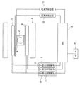
図1はこの発明の実施の形態1による磁気共鳴イメージング装置を一部ブロックで示す構成図である。静磁場発生磁石1は、均一な静磁場空間を発生することにより、磁場の均一領域2を形成する。
Hereinafter, embodiments for carrying out the present invention will be described with reference to the drawings.
Embodiment 1 FIG.
1 is a block diagram showing a part of a magnetic resonance imaging apparatus according to Embodiment 1 of the present invention. The static magnetic field generating magnet 1 forms a uniform
傾斜磁場コイル装置3は、被検体の位置情報を与えるために、互いに直交する3軸方向に磁場強度が線形に変化する傾斜磁場を発生する。傾斜磁場コイル装置3は、静磁場発生磁石1よりも均一領域2側に配置されている。
The gradient coil device 3 generates a gradient magnetic field whose magnetic field intensity changes linearly in three axis directions orthogonal to each other in order to give position information of the subject. The gradient magnetic field coil device 3 is disposed closer to the
傾斜磁場コイル装置3は、傾斜磁場電源部4に接続されている。傾斜磁場電源部4は、X傾斜磁場電源5、Y傾斜磁場電源6及びZ傾斜磁場電源7を有している。これら傾斜磁場コイル装置3及び傾斜磁場電源部4により、傾斜磁場発生手段が構成されている。 The gradient magnetic field coil device 3 is connected to the gradient magnetic field power supply unit 4. The gradient magnetic field power supply unit 4 includes an X gradient magnetic field power supply 5, a Y gradient magnetic field power supply 6, and a Z gradient magnetic field power supply 7. The gradient magnetic field coil device 3 and the gradient magnetic field power supply unit 4 constitute a gradient magnetic field generating means.
傾斜磁場コイル装置3よりも均一領域2側には、プロトンの共鳴周波数を持つ電磁波を送信するRF(高周波)コイル8、及び検査部位のNMR信号を受信する受信コイル9が配置されている。
An RF (high frequency)
RFコイル8には、高周波電力を供給する高周波送信器10が接続されている。受信コイル9には、受信した信号を増幅する高周波受信器11が接続されている。これら高周波送信器10及び高周波受信器11により、高周波送受信系が構成されている。
The
傾斜磁場電源部4、高周波送信器10及び高周波受信器11は、これらの動作を制御するためのPC(パーソナルコンピュータ)12に接続されている。PC12は、高周波受信器11によって増幅されたNMR信号に演算処理を施し、画像を構成する機能を有している。
The gradient magnetic field power supply unit 4, the
PC12には、モニタ13が接続されている。PC12は、演算処理により得られた画像、及び設定画面をモニタ13に表示させる。設定画面は、操作者が計測の条件を設定したりパルスシーケンスの選択を行ったりするための画面である。
A
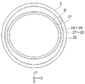
図2は図1の傾斜磁場コイル装置3を示す正面図、図3は図2のIII部を拡大して示す正面図である。傾斜磁場コイル装置3は、筒状の傾斜磁場コイル装置本体21を有している。傾斜磁場コイル装置本体21の内周の断面(傾斜磁場コイル装置本体21の軸方向に直角な断面)は、短軸が鉛直で長軸が水平な楕円形である。また、傾斜磁場コイル装置本体21の外周の断面は、円形である。
2 is a front view showing the gradient magnetic field coil device 3 of FIG. 1, and FIG. 3 is an enlarged front view showing a portion III of FIG. The gradient coil device 3 has a cylindrical gradient
傾斜磁場コイル装置本体21の壁部内には、X、Y及びZの3軸方向の傾斜磁場を発生する傾斜磁場コイルである複数のメインXコイル24、複数のメインYコイル25及びメインZコイル25が配置されている。
In the wall portion of the gradient magnetic field coil device
図2では、これらのメインコイル24〜26をまとめて示している。また、これらのメインコイル24〜26は、全体として楕円筒形をなすように配置されている。
In FIG. 2, these main coils 24-26 are shown collectively. Further, these
傾斜磁場コイル装置本体21の壁部内のメインコイル24〜26よりも径方向外側には、メインコイル24〜26による漏れ磁場を防ぐ傾斜磁場コイルである複数のシールドXコイル27、複数のシールドYコイル28及びシールドZコイル29が配置されている。
A plurality of shield X coils 27 and a plurality of shield Y coils, which are gradient magnetic field coils that prevent leakage magnetic fields from the
図2では、これらのシールドコイル27〜29をまとめて示している。また、シールドコイル27〜29は、全体して、メインコイル24〜26を囲繞する円筒形をなすように配置されている。
In FIG. 2, these shield coils 27 to 29 are shown together. The shield coils 27 to 29 are arranged so as to form a cylindrical shape surrounding the
傾斜磁場コイル装置本体21は、これらの傾斜磁場コイル24〜29を樹脂等のモールド材22によってモールドして構成されている。
The gradient magnetic field coil device
傾斜磁場コイル24〜29は、傾斜磁場コイル装置本体21の径方向中心側から径方向外側へ向けて、メインXコイル24、メインYコイル25、メインZコイル26、シールドZコイル29、シールドYコイル28、シールドXコイル27の順に配置されている。
The gradient magnetic field coils 24 to 29 are a
傾斜磁場コイル装置本体21の内周の断面形状を、上下方向寸法が左右方向寸法よりも短い楕円形とする場合、メインXコイル24が磁場中心から遠く、メインYコイル25が磁場中心に近くなるが、上記のような順番に配置することで、メインXコイル24の傾斜磁場効率を高めることができる。
When the cross-sectional shape of the inner periphery of the gradient magnetic field coil device
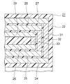
図4は図3のメインXコイル24及びシールドXコイル27のパターンを平面に展開して示す説明図であり、簡単のためターン数は実際よりも少なく描いている。図4では、メインXコイル24とシールドXコイル27とが傾斜磁場コイル装置本体21の軸方向(図4の左右方向)にずらされているが、実際にはメインXコイル24の径方向外側にシールドXコイル27が配置されている。
FIG. 4 is an explanatory diagram showing the pattern of the
また、図4では、傾斜磁場コイル装置本体21の軸方向の中心Cの両側にメインXコイル24及びシールドXコイル27が1組ずつ配置されているが、実際には、あと2組のメインXコイル24及びシールドXコイル27が傾斜磁場コイル装置本体21の周方向に間隔をおいて配置されている。即ち、傾斜磁場コイル装置本体21には、4組のメインXコイル24及びシールドXコイル27が配置されている。
In FIG. 4, one set of
メインXコイル24とそれに対応するシールドXコイル27とは、図4に点線で示した複数のX接続部31により互いに電気的に接続されている。X接続部31は、メインXコイル24及びシールドXコイル27の複数のターン間に設けられている。これにより、メインXコイル24の一部のターンとシールドXコイル27の一部のターンとの間では、電流がメインXコイル24とシールドXコイル27とを交互に流れるようになっている。
The
メインYコイル25及びシールドYコイル28の構成及び個数は、メインXコイル24及びシールドXコイル27と同様である。メインYコイル25及びシールドYコイル28は、メインXコイル24及びシールドXコイル27に対して傾斜磁場コイル装置本体21の周方向に90°ずらして配置されている。
The configuration and number of the
また、メインYコイル25とそれに対応するシールドYコイル28とは、X接続部31と同様の複数のY接続部32(図5)により互いに電気的に接続されている。
The
メインZコイル26及びシールドZコイル29は、傾斜磁場コイル装置本体21の軸線を中心としたソレノイドコイル状に配置されている。また、メインZコイル26とシールドZコイル29とは、Z接続部33(図5)により互いに電気的に接続されている。なお、図2及び図3では、X接続部31、Y接続部32及びZ接続部33の図示を省略した。
The
図5は図2の傾斜磁場コイル装置本体21の軸方向端部の縦断面図であり、図5の左右方向が傾斜磁場コイル装置本体21の軸方向(図2のZ軸方向)である。また、図5の左側が磁場中心側である。
FIG. 5 is a longitudinal sectional view of the end portion in the axial direction of the gradient magnetic field coil apparatus
X接続部31、Y接続部32及びZ接続部33は、傾斜磁場コイル装置本体21の軸方向端部に配置されている。また、傾斜磁場コイル装置本体21の軸方向への傾斜磁場コイル24〜29の長さは、互いに異なっており、短い方からZ、Y、Xの順となっている。
The
そして、接続部31〜33は、磁場中心側から、Z、Y、Xの順で配置されている。即ち、X接続部31、Y接続部32及びZ接続部33は、傾斜磁場コイル装置本体21の軸方向に互いにずらして配置されている。さらに、X接続部31、Y接続部32及びZ接続部33は、それぞれ立体配線として、傾斜磁場コイル装置本体21の径方向に平行に配置されている。
And the connection parts 31-33 are arrange | positioned in order of Z, Y, X from the magnetic field center side. That is, the
X接続部31は、メインXコイル24とシールドXコイル27とにそれぞれねじ止めされ、かつ半田付けされている。Y接続部32は、メインYコイル25とシールドYコイル28とにそれぞれねじ止めされ、かつ半田付けされている。Z接続部33は、メインZコイル26とシールドZコイル29とにそれぞれねじ止めされ、かつ半田付けされている。
The
傾斜磁場コイル装置本体21は、X接続部31、Y接続部32及びZ接続部33の接続後に、X接続部31、Y接続部32及びZ接続部33を含めてモールドされている。これにより、X接続部31、Y接続部32及びZ接続部33は、モールド材22内に埋設されている。
The gradient
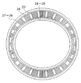
図6は図2の傾斜磁場コイル装置本体21の軸方向に直角な断面(横断面)を示す断面図である。傾斜磁場コイル装置本体21の径方向におけるメインコイル24〜26の配置領域とシールドコイル27〜29の配置領域との間には、複数のシムトレイ収容部(シムトレイ鞘)23(図2、3では図示を省略した)が設けられている。
6 is a cross-sectional view showing a cross section (transverse cross section) perpendicular to the axial direction of the gradient
シムトレイ収容部23は、傾斜磁場コイル装置本体21の周方向に互いに間隔をおいて配置されている。各シムトレイ収容部23には、静磁場を均一にするための鉄部材を保持するシムトレイが挿入されている。
The shim
シムトレイ収容部23は、静磁場の補正を行う際にシムトレイの出し入れが可能となっている必要がある。このため、X接続部31、Y接続部32及びZ接続部33は、傾斜磁場コイル装置本体21の周方向のシムトレイ収容部23を避けた位置に配置される。
The shim
即ち、傾斜磁場コイル装置本体21は、その周方向に互いに間隔をおいて複数の立体配線可能領域34を有している。そして、これらの中から適宜選択された立体配線可能領域34に、X接続部31、Y接続部32及びZ接続部33を配置することができる。
That is, the gradient coil device
このような傾斜磁場コイル装置3及びそれを用いた磁気共鳴イメージング装置では、傾斜磁場コイル24〜26が、傾斜磁場コイル装置本体21の径方向中心側から径方向外側へ向けて、メインXコイル24、メインYコイル25、メインZコイル26、シールドZコイル29、シールドYコイル28、シールドXコイル27の順に配置されており、X接続部31及びY接続部32が傾斜磁場コイル装置本体21の軸方向に互いにずらして配置されているので、X接続部31及びY接続部32を傾斜磁場コイル装置本体21の周方向の同じ位置に、互いに干渉することなく配置することができる。
In the gradient magnetic field coil device 3 and the magnetic resonance imaging apparatus using the gradient magnetic field coil device 3, the gradient magnetic field coils 24 to 26 are arranged so that the
このため、十分なシールド性能を維持しつつ、静磁場の急変部に配置されるシールドコイル27〜29を減らすことができ、ローレンツ力を低下させて振動を減少させることができる。 For this reason, it is possible to reduce the number of shield coils 27 to 29 arranged at the sudden change portion of the static magnetic field while maintaining sufficient shielding performance, and it is possible to reduce the Lorentz force and reduce the vibration.
また、全ての立体配線可能領域34にX接続部31及びY接続部32を配置することができ、立体配線の設計の自由度が向上する。これにより、メインXコイル24とシールドXコイル27との間、及びメインYコイル25とシールドYコイル28との間を、より多くのターン間で接続することができ、静磁場の急変部に配置されるシールドコイル27〜29をさらに少なくすることができる。
Moreover, the
また、傾斜磁場コイル装置本体21の内周の断面が楕円形であるため、被検体が受ける閉塞感を低減することができる。
Moreover, since the cross section of the inner periphery of the gradient magnetic field coil apparatus
実施の形態2.
次に、図7はこの発明の実施の形態2による傾斜磁場コイル装置本体21の軸方向端部の縦断面図である。この例では、傾斜磁場コイル装置本体21の軸方向(図7の左右方向)へのシールドコイル27〜29の長さが互いに同じであり、かつメインZコイル26よりも短くなっている。また、X接続部31、Y接続部32及びZ接続部33は、傾斜磁場コイル装置本体21の径方向に対して傾斜して配置されている。
Next, FIG. 7 is a longitudinal sectional view of an axial end portion of the gradient
より詳細には、X接続部31、Y接続部32及びZ接続部33は、傾斜磁場コイル装置本体21の径方向外側へ行くほど、傾斜磁場コイル装置本体21の軸方向の磁場中心側へ向かうように傾斜している。
More specifically, the
これにより、傾斜磁場コイル装置本体21の軸方向端部には、追加機器設置領域(隙間)35が確保されている。追加機器設置領域35には、例えば、冷媒が通される冷却管、又は傾斜磁場コイル装置本体21の変形を防止する補強部材等を配置することができる。
Thereby, an additional device installation area (gap) 35 is secured at the axial end of the gradient magnetic field coil device
なお、メインコイル24〜26に対するシールド性能は、シールドコイル27〜29及び接続部31〜33により確保されている。他の構成及び磁気共鳴イメージング装置全体の構成は、実施の形態1と同様である。 In addition, the shielding performance with respect to the main coils 24-26 is ensured by the shield coils 27-29 and the connection parts 31-33. Other configurations and the entire configuration of the magnetic resonance imaging apparatus are the same as those in the first embodiment.
このような構成によれば、実施の形態1と同様の効果に加えて、冷却管又は補強部材等の追加機器を傾斜磁場コイル装置本体21内に設置することができ、傾斜磁場コイル装置全体としての性能を向上させることができる。
According to such a configuration, in addition to the same effects as those of the first embodiment, an additional device such as a cooling pipe or a reinforcing member can be installed in the gradient magnetic field coil device
実施の形態3.
次に、図8はこの発明の実施の形態3による傾斜磁場コイル装置本体21の軸方向に直角な断面(横断面)を示す断面図である。この例では、傾斜磁場コイル装置本体21の周方向の位置によってシムトレイ収容部23の形状が異なっている。
Embodiment 3 FIG.
Next, FIG. 8 is a cross-sectional view showing a cross section (transverse cross section) perpendicular to the axial direction of the gradient
即ち、傾斜磁場コイル装置本体21の横断面の短軸方向に配置されたシムトレイ収容部23では、従来の面積を保ったまま、傾斜磁場コイル装置本体21の径方向への寸法が周方向への寸法よりも大きくなっている。そして、長軸方向に配置されたシムトレイ収容部23ほど、径方向への寸法が小さく、周方向への寸法が大きくなっている。
That is, in the shim
これにより、互いに隣接するシムトレイ収容部23間の隙間、即ち立体配線可能領域34は、短軸方向で広く、長軸方向では従来と同じとなる。他の構成及び磁気共鳴イメージング装置全体の構成は、実施の形態1と同様である。
As a result, the gap between the shim
このような構成では、X接続部31及びY接続部32の数を短軸方向で多くすることができ、シールド性能を高めることができる。これにより、シールドコイルの長さをさらに短くすることができ、例えば図7に示した追加機器設置領域35を増やすこともできる。
In such a configuration, the number of
なお、メインZコイル26とシールドZコイル29とは必ずしも接続しなくてもよい。また、接続する場合、Z接続部33の数は1つでもよい。
また、全てのX接続部31と全てのY接続部32とが傾斜磁場コイル装置本体21の周方向の同じ位置に配置されている必要はなく、少なくとも一部のX接続部31と少なくとも一部のY接続部32とが同じ立体配線可能領域34に配置されていればよい。
さらに、Z接続部33は、必ずしもX接続部31及びY接続部32と同じ立体配線可能領域34に配置しなくてもよい。
The
Further, it is not necessary that all the
Furthermore, the
3 傾斜磁場コイル装置、21 傾斜磁場コイル装置本体、23 シムトレイ収容部、24 メインXコイル、25 メインYコイル、26 メインZコイル、27 シールドXコイル、28 シールドYコイル、29 シールドZコイル、31 X接続部、32 Y接続部。 3 Gradient Magnetic Field Coil Device, 21 Gradient Magnetic Field Coil Device Main Body, 23 Shim Tray Housing, 24 Main X Coil, 25 Main Y Coil, 26 Main Z Coil, 27 Shield X Coil, 28 Shield Y Coil, 29 Shield Z Coil, 31 X Connection part, 32 Y connection part.
Claims (5)
前記傾斜磁場コイルは、前記傾斜磁場コイル装置本体の径方向中心側から径方向外側へ向けて、前記メインXコイル、前記メインYコイル、前記メインZコイル、前記シールドZコイル、前記シールドYコイル、前記シールドXコイルの順に配置されており、
前記傾斜磁場コイル装置本体の軸方向端部には、前記メインXコイルと前記シールドXコイルとを接続する複数のX接続部と、前記メインYコイルと前記シールドYコイルとを接続する複数のY接続部とが設けられており、
前記X接続部及び前記Y接続部は、前記傾斜磁場コイル装置本体の軸方向に互いにずらして配置されていることを特徴とする傾斜磁場コイル装置。 A main X coil, a main Y coil, and a main Z coil that generate gradient magnetic fields in the X, Y, and Z directions, and a shield X coil that prevents a leakage magnetic field from the main X coil, the main Y coil, and the main Z coil A plurality of gradient magnetic field coils including a shield Y coil and a shield Z coil, and a cylindrical gradient magnetic field coil device main body having an elliptical inner cross section,
The gradient magnetic field coils are arranged such that the main X coil, the main Y coil, the main Z coil, the shield Z coil, the shield Y coil, Arranged in the order of the shield X coil,
A plurality of X connection portions for connecting the main X coil and the shield X coil, and a plurality of Y for connecting the main Y coil and the shield Y coil to the axial end of the gradient magnetic field coil apparatus main body. And a connecting part,
The gradient magnetic field coil device, wherein the X connection portion and the Y connection portion are arranged to be shifted from each other in the axial direction of the gradient magnetic field coil device body.
前記X接続部及び前記Y接続部は、互いに隣接する前記シムトレイ収容部間の隙間に配置されていることを特徴とする請求項1又は請求項2に記載の傾斜磁場コイル装置。 In the gradient coil device body, a plurality of shim tray accommodating portions are arranged at intervals in the circumferential direction,
The gradient magnetic field coil apparatus according to claim 1, wherein the X connection part and the Y connection part are arranged in a gap between the shim tray housing parts adjacent to each other.
Priority Applications (1)
| Application Number | Priority Date | Filing Date | Title |
|---|---|---|---|
| JP2014005964A JP2015134017A (en) | 2014-01-16 | 2014-01-16 | Gradient magnetic field coil device and magnetic resonance imaging apparatus using the same |
Applications Claiming Priority (1)
| Application Number | Priority Date | Filing Date | Title |
|---|---|---|---|
| JP2014005964A JP2015134017A (en) | 2014-01-16 | 2014-01-16 | Gradient magnetic field coil device and magnetic resonance imaging apparatus using the same |
Publications (2)
| Publication Number | Publication Date |
|---|---|
| JP2015134017A true JP2015134017A (en) | 2015-07-27 |
| JP2015134017A5 JP2015134017A5 (en) | 2017-02-23 |
Family
ID=53766388
Family Applications (1)
| Application Number | Title | Priority Date | Filing Date |
|---|---|---|---|
| JP2014005964A Ceased JP2015134017A (en) | 2014-01-16 | 2014-01-16 | Gradient magnetic field coil device and magnetic resonance imaging apparatus using the same |
Country Status (1)
| Country | Link |
|---|---|
| JP (1) | JP2015134017A (en) |
Citations (5)
| Publication number | Priority date | Publication date | Assignee | Title |
|---|---|---|---|---|
| JPH0884716A (en) * | 1994-09-16 | 1996-04-02 | Toshiba Corp | Gradient magnetic field coil |
| US6236209B1 (en) * | 1998-10-28 | 2001-05-22 | Siemens Aktiengesellschaft | Actively shielded, transversal gradient coil system with 3D connection technology |
| JP2011115480A (en) * | 2009-12-07 | 2011-06-16 | Hitachi Medical Corp | Magnetic resonance imaging apparatus, and method of adjusting magnetic field homogeneity of the apparatus |
| JP2012034807A (en) * | 2010-08-06 | 2012-02-23 | Hitachi Medical Corp | Gradient magnetic field coil and magnetic resonance imaging apparatus |
| WO2013122202A1 (en) * | 2012-02-17 | 2013-08-22 | 株式会社 日立メディコ | Gradient coil and magnetic resonance imaging device |
-
2014
- 2014-01-16 JP JP2014005964A patent/JP2015134017A/en not_active Ceased
Patent Citations (6)
| Publication number | Priority date | Publication date | Assignee | Title |
|---|---|---|---|---|
| JPH0884716A (en) * | 1994-09-16 | 1996-04-02 | Toshiba Corp | Gradient magnetic field coil |
| US6236209B1 (en) * | 1998-10-28 | 2001-05-22 | Siemens Aktiengesellschaft | Actively shielded, transversal gradient coil system with 3D connection technology |
| JP2011115480A (en) * | 2009-12-07 | 2011-06-16 | Hitachi Medical Corp | Magnetic resonance imaging apparatus, and method of adjusting magnetic field homogeneity of the apparatus |
| JP2012034807A (en) * | 2010-08-06 | 2012-02-23 | Hitachi Medical Corp | Gradient magnetic field coil and magnetic resonance imaging apparatus |
| WO2013122202A1 (en) * | 2012-02-17 | 2013-08-22 | 株式会社 日立メディコ | Gradient coil and magnetic resonance imaging device |
| JP2013165921A (en) * | 2012-02-17 | 2013-08-29 | Hitachi Medical Corp | Gradient coil, and magnetic resonance imaging apparatus |
Similar Documents
| Publication | Publication Date | Title |
|---|---|---|
| US8466681B2 (en) | Open-type MRI apparatus, and open-type superconducting MRI apparatus | |
| JP2005199047A (en) | Coolant cooled rf body coil | |
| JP6462292B2 (en) | Magnetic resonance imaging system | |
| KR101600886B1 (en) | Magnetic resonance imaging apparatus | |
| JP7094716B2 (en) | Inclined magnetic field coil | |
| JP2010148857A (en) | High frequency coil unit and magnetic resonance diagnostic apparatus | |
| JP2017099502A (en) | Magnetic resonance imaging device | |
| JP2010508880A (en) | Split gradient coil for MRI | |
| US7230426B2 (en) | Split-shield gradient coil with improved fringe-field | |
| JP2015134017A (en) | Gradient magnetic field coil device and magnetic resonance imaging apparatus using the same | |
| US10656225B2 (en) | Magnetic resonance imaging apparatus | |
| JP6296631B2 (en) | Magnetic resonance imaging system | |
| JP2019000525A (en) | Magnetic resonance imaging apparatus | |
| JP6245993B2 (en) | Magnetic resonance imaging apparatus and shim tray | |
| JP2010263955A (en) | Gradient magnetic field coil unit | |
| JP6444433B2 (en) | Magnetic resonance imaging system | |
| JP7014548B2 (en) | Magnetic resonance imaging device | |
| JP5901561B2 (en) | Magnetic resonance imaging system | |
| KR102290714B1 (en) | Electro magnetic interference shielding coil for an mri system | |
| JP5465583B2 (en) | Magnetic resonance imaging system | |
| JP6912321B2 (en) | Magnetic resonance imaging device | |
| JP2017099501A (en) | Rf coil and magnetic resonance imaging device | |
| JP2013146283A (en) | Magnetic resonance imaging apparatus | |
| JP2014180446A (en) | Gradient magnetic field coil unit and magnetic resonance imaging apparatus | |
| JP2020010984A (en) | Magnetic body installation method and arithmetic device |
Legal Events
| Date | Code | Title | Description |
|---|---|---|---|
| RD04 | Notification of resignation of power of attorney |
Free format text: JAPANESE INTERMEDIATE CODE: A7424 Effective date: 20160330 |
|
| A711 | Notification of change in applicant |
Free format text: JAPANESE INTERMEDIATE CODE: A712 Effective date: 20160427 |
|
| A521 | Request for written amendment filed |
Free format text: JAPANESE INTERMEDIATE CODE: A523 Effective date: 20161226 |
|
| A621 | Written request for application examination |
Free format text: JAPANESE INTERMEDIATE CODE: A621 Effective date: 20161226 |
|
| RD02 | Notification of acceptance of power of attorney |
Free format text: JAPANESE INTERMEDIATE CODE: A7422 Effective date: 20171031 |
|
| RD04 | Notification of resignation of power of attorney |
Free format text: JAPANESE INTERMEDIATE CODE: A7424 Effective date: 20171107 |
|
| A977 | Report on retrieval |
Free format text: JAPANESE INTERMEDIATE CODE: A971007 Effective date: 20171122 |
|
| A131 | Notification of reasons for refusal |
Free format text: JAPANESE INTERMEDIATE CODE: A131 Effective date: 20171205 |
|
| A521 | Request for written amendment filed |
Free format text: JAPANESE INTERMEDIATE CODE: A523 Effective date: 20180125 |
|
| A01 | Written decision to grant a patent or to grant a registration (utility model) |
Free format text: JAPANESE INTERMEDIATE CODE: A01 Effective date: 20180417 |
|
| A045 | Written measure of dismissal of application [lapsed due to lack of payment] |
Free format text: JAPANESE INTERMEDIATE CODE: A045 Effective date: 20180828 |