JP2015123784A - vehicle - Google Patents

vehicle Download PDF

Info

Publication number
JP2015123784A
JP2015123784A JP2013267752A JP2013267752A JP2015123784A JP 2015123784 A JP2015123784 A JP 2015123784A JP 2013267752 A JP2013267752 A JP 2013267752A JP 2013267752 A JP2013267752 A JP 2013267752A JP 2015123784 A JP2015123784 A JP 2015123784A
Authority
JP
Japan
Prior art keywords
power
speed
battery
gear
motor
Prior art date
Legal status (The legal status is an assumption and is not a legal conclusion. Google has not performed a legal analysis and makes no representation as to the accuracy of the status listed.)
Granted
Application number
JP2013267752A
Other languages
Japanese (ja)
Other versions
JP6356419B2 (en
Inventor
孔人 寺山
Yoshito Terayama
孔人 寺山
義紀 安藤
Yoshinori Ando
義紀 安藤
真利 野口
Shinri Noguchi
真利 野口
雄亮 阪口
Yusuke Sakaguchi
雄亮 阪口
昌樹 根來
Masaki Negoro
昌樹 根來
純和 藤本
Sumikazu Fujimoto
純和 藤本
Current Assignee (The listed assignees may be inaccurate. Google has not performed a legal analysis and makes no representation or warranty as to the accuracy of the list.)
Honda Motor Co Ltd
Original Assignee
Honda Motor Co Ltd
Priority date (The priority date is an assumption and is not a legal conclusion. Google has not performed a legal analysis and makes no representation as to the accuracy of the date listed.)
Filing date
Publication date
Application filed by Honda Motor Co Ltd filed Critical Honda Motor Co Ltd
Priority to JP2013267752A priority Critical patent/JP6356419B2/en
Publication of JP2015123784A publication Critical patent/JP2015123784A/en
Application granted granted Critical
Publication of JP6356419B2 publication Critical patent/JP6356419B2/en
Expired - Fee Related legal-status Critical Current
Anticipated expiration legal-status Critical

Links

Images

Classifications

    • YGENERAL TAGGING OF NEW TECHNOLOGICAL DEVELOPMENTS; GENERAL TAGGING OF CROSS-SECTIONAL TECHNOLOGIES SPANNING OVER SEVERAL SECTIONS OF THE IPC; TECHNICAL SUBJECTS COVERED BY FORMER USPC CROSS-REFERENCE ART COLLECTIONS [XRACs] AND DIGESTS
    • Y02TECHNOLOGIES OR APPLICATIONS FOR MITIGATION OR ADAPTATION AGAINST CLIMATE CHANGE
    • Y02TCLIMATE CHANGE MITIGATION TECHNOLOGIES RELATED TO TRANSPORTATION
    • Y02T10/00Road transport of goods or passengers
    • Y02T10/60Other road transportation technologies with climate change mitigation effect
    • Y02T10/62Hybrid vehicles
    • YGENERAL TAGGING OF NEW TECHNOLOGICAL DEVELOPMENTS; GENERAL TAGGING OF CROSS-SECTIONAL TECHNOLOGIES SPANNING OVER SEVERAL SECTIONS OF THE IPC; TECHNICAL SUBJECTS COVERED BY FORMER USPC CROSS-REFERENCE ART COLLECTIONS [XRACs] AND DIGESTS
    • Y02TECHNOLOGIES OR APPLICATIONS FOR MITIGATION OR ADAPTATION AGAINST CLIMATE CHANGE
    • Y02TCLIMATE CHANGE MITIGATION TECHNOLOGIES RELATED TO TRANSPORTATION
    • Y02T10/00Road transport of goods or passengers
    • Y02T10/60Other road transportation technologies with climate change mitigation effect
    • Y02T10/72Electric energy management in electromobility

Landscapes

  • Hybrid Electric Vehicles (AREA)
  • Structure Of Transmissions (AREA)
  • Electric Propulsion And Braking For Vehicles (AREA)

Abstract

PROBLEM TO BE SOLVED: To provide a vehicle in which over discharge of a battery can be prevented in a case of occurrence of an event that an electric power generator cannot generate electric power, in a vehicle which is driven by an electric motor that drives a wheel through receiving electric power supplied from the electric power generator which performs electric power generation by a rotation driving force of an internal combustion engine and electric power supplied from the battery.SOLUTION: When electric power generation Pgen of an electric motor 14 which functions as an electric power generator is limited, generation of unnecessary deceleration torque from a first and a second electric motors 22A, 22B is prevented while suppressing outgoing electric power Pd from a battery 24 by implementing a 0 (Nm) control on the first and the second electric motors 22A, 22B, and, when outgoing electric power Pd from the battery 24 also must be limited, generation of outgoing electric power Pd from the battery 24 to the first and the second electric motors 22A, 22B is prevented by implementing a 0 (kW) control.

Description

この発明は、前輪(左前輪と右前輪)及び後輪(左後輪と右後輪)の少なくとも一方の車輪に機械的に接続される電動機と、内燃機関に機械的に接続される発電機と、前記電動機及び前記発電機に電気的に接続される蓄電器と、前記電動機を制御する電動機制御装置と、を備える車両に関する。   The present invention relates to an electric motor mechanically connected to at least one of a front wheel (left front wheel and right front wheel) and a rear wheel (left rear wheel and right rear wheel), and a generator mechanically connected to an internal combustion engine. And a battery that is electrically connected to the electric motor and the generator, and an electric motor control device that controls the electric motor.

特許文献1には、バッテリの電力がインバータを通じて電動機に供給され、前記電動機の動力により車輪を駆動する車両が開示されている(図1、図20)。また、特許文献1には、前記インバータへの供給電力がゼロ値であっても、前記電動機にトルクが発生することが開示されている([0092]、[0093])。このように、電動機への電力の入力が0[kW]であっても、前記電動機には、例えばロータに組み込まれた永久磁石とコイルが巻回されたステータのコアとの間の吸引力(鉄損)等による負のトルク(ロータを回り難くする抵抗力)が発生する。この負のトルクは、予め試験的にあるいは計算により求めることができる([0093])。   Patent Document 1 discloses a vehicle in which battery power is supplied to an electric motor through an inverter and wheels are driven by the power of the electric motor (FIGS. 1 and 20). Patent Document 1 discloses that torque is generated in the electric motor even when the power supplied to the inverter is zero ([0092], [0093]). Thus, even if the input of electric power to the electric motor is 0 [kW], the electric motor has, for example, an attractive force (e.g., a permanent magnet built in the rotor and a stator core wound with a coil). Negative torque (resistance force that makes it difficult to turn the rotor) occurs due to iron loss. This negative torque can be obtained in advance by trial or calculation ([0093]).

以下、この明細書において、電動機への電力入力を0(ゼロ、零)値とする制御を0[kW]制御(0kW制御ともいう。)という。なお、0[kW]制御時においては、バッテリから電動機側に流出される電力値が、ゼロ値であることに留意する。   Hereinafter, in this specification, the control for setting the power input to the electric motor to 0 (zero, zero) value is referred to as 0 [kW] control (also referred to as 0 kW control). It should be noted that during 0 [kW] control, the power value that flows out from the battery to the motor side is a zero value.

特許文献2には、上述した負のトルクを原因とする抵抗力を相殺する制御が記載されている。例えば、永久磁石同期電動機では、電動機に0(ゼロ、零)トルク指令を与えた状態で、電気角度と、角速度と、3相中2相の相電流を検出して電動機損失(モータ損失)を取得し、取得される電動機損失がゼロ値となるようにインバータを通じて電動機をゼロトルク状態に制御すればよいことが開示されている([0095]、[0096])。   Patent Document 2 describes control for canceling the resistance force caused by the negative torque described above. For example, in a permanent magnet synchronous motor, a motor loss (motor loss) is detected by detecting an electrical angle, an angular velocity, and a phase current of two phases out of three phases in a state where a torque command is given to the motor. It is disclosed that the motor may be controlled to a zero torque state through an inverter so that the acquired motor loss becomes zero ([0095], [0096]).

以下、この明細書において、電動機が発生するトルクをゼロ値にする制御を0[Nm]制御(0Nm制御ともいう。)という。なお、0[Nm]制御時においては、電動機が電力を消費する点に留意する。   Hereinafter, in this specification, control for setting the torque generated by the electric motor to zero is referred to as 0 [Nm] control (also referred to as 0 Nm control). Note that the motor consumes electric power during 0 [Nm] control.

特許文献3には、前輪(左前輪と右前輪)及び後輪(左後輪と右後輪)の一方が駆動される車両が開示されている(図1、[0127])。   Patent Document 3 discloses a vehicle in which one of a front wheel (left front wheel and right front wheel) and a rear wheel (left rear wheel and right rear wheel) is driven (FIG. 1, [0127]).

特許文献3には、後輪(左後輪と右後輪)駆動走行中に、一方の後輪に超過スリップが発生したとき、超過スリップが発生した後輪の駆動トルクを低減すると共に、ヨーモーメントが発生しないように、他方の後輪の駆動トルクもその分低減し、且つ車両の駆動力が低下しないように、前輪(左前輪と右前輪)に低減した駆動トルクを配分するように構成する車両用駆動装置が開示されている{[0082]−[0085]、図20(a)、図20(b)、図20(c)}。   In Patent Document 3, when an excessive slip occurs in one rear wheel during driving of the rear wheels (the left rear wheel and the right rear wheel), the driving torque of the rear wheel in which the excess slip has occurred is reduced, and The drive torque of the other rear wheel is reduced by that amount so that no moment is generated, and the reduced drive torque is distributed to the front wheels (left front wheel and right front wheel) so that the drive force of the vehicle does not decrease. {[0082]-[0085], FIG. 20 (a), FIG. 20 (b), FIG. 20 (c)}.

特許文献4には、内燃機関と発電機としても動作する電動機との間にダブルクラッチにより切り替えられる変速機を備え、且つ前記内燃機関が前記電動機に直列に接続されたハイブリッド車両用の駆動装置(ハイブリッド駆動装置)が開示されている(図1)。   Patent Document 4 discloses a drive device for a hybrid vehicle that includes a transmission that is switched by a double clutch between an internal combustion engine and an electric motor that also operates as a generator, and in which the internal combustion engine is connected in series to the electric motor ( Hybrid drive device) is disclosed (FIG. 1).

特開2012−239264号公報JP 2012-239264 A 特開2012−218562号公報JP 2012-218562 A 特開2013−215017号公報JP 2013-2105017 A 特開2011−79379号公報JP 2011-79379 A

ところで、特許文献3に開示されている前輪(左前輪と右前輪)及び後輪(左後輪と右後輪)の一方の車輪が左右の電動機からなる駆動装置(電動機駆動装置)により駆動される車両に対して、他方の車輪を特許文献4に開示されたダブルクラッチにより切り替えられる変速機を備える駆動装置(ハイブリッド駆動装置)により駆動する全輪駆動が可能な車両を想到することができる。   Incidentally, one of the front wheels (the left front wheel and the right front wheel) and the rear wheels (the left rear wheel and the right rear wheel) disclosed in Patent Document 3 is driven by a drive device (motor drive device) including left and right electric motors. It is possible to conceive a vehicle capable of all-wheel drive in which the other wheel is driven by a drive device (hybrid drive device) having a transmission that can be switched by the double clutch disclosed in Patent Document 4.

しかしながら、[発明を実施するための形態]の項で後述するように、このように想到される全輪駆動が可能な車両において、電動機駆動装置により一方の車輪を駆動しながら、ハイブリッド駆動装置側では内燃機関により車輪を駆動すると共に電動機を発電機として機能させて発電し、この発電電力を電動機駆動装置に供給して走行している状態において、前記変速機の変速段を切り替えようとする際に、発電機として動作させている電動機を停止させなければならない事態(発電減少状態又は発電抜け状態という。)が発生し、その発電減少状態(発電抜け状態)時に、バッテリから前記電動機駆動装置に電力を供給すると、前記バッテリが過放電状態に陥る可能性が発生するという課題がある。   However, as will be described later in the section “DETAILED DESCRIPTION OF THE INVENTION”, in the vehicle capable of all-wheel drive thus conceived, while driving one wheel by the motor drive device, the hybrid drive device side In the state where the wheels are driven by the internal combustion engine and the electric motor functions as a generator to generate electric power, and the generated electric power is supplied to the electric motor driving device and the vehicle is running, the gear stage of the transmission is to be switched. In addition, there is a situation in which the motor operating as a generator must be stopped (referred to as a power generation reduced state or a power generation missing state), and when the power generation is reduced (power generation lost state), the battery drives the motor drive device. When power is supplied, there is a problem that the battery may be in an overdischarged state.

この発明は、上記した技術及び課題に関連してなされたものであり、内燃機関の回転駆動力により発電する発電機及び/又は蓄電器からの電力が供給されて、前輪及び後輪の少なくとも一方を駆動する電動機により走行する車両において、前記発電機を発電させることができない事態が発生したときに、前記蓄電器の放電過多を防止し、蓄電器を保護することを可能とする車両を提供することを目的とする。   The present invention has been made in connection with the above-described technique and problem, and is supplied with electric power from a generator and / or a capacitor that generates electric power by the rotational driving force of an internal combustion engine, and at least one of a front wheel and a rear wheel is supplied. An object of the present invention is to provide a vehicle capable of preventing excessive discharge of the capacitor and protecting the capacitor when a situation in which the generator cannot generate power occurs in a vehicle that is driven by a driving electric motor. And

この発明に係る車両は、前輪及び後輪の少なくとも一方の車輪に機械的に接続される電動機と、内燃機関に機械的に接続される発電機と、前記電動機及び前記発電機に電気的に接続される蓄電器と、前記電動機を制御する電動機制御装置と、を備え、前記電動機制御装置は、前記発電機が発生する電力が制限される発電制限状態を取得又は予測したときに、前記電動機が発生する動力を略ゼロ値にするゼロ動力制御を実行し、該ゼロ動力制御の実行中に前記蓄電器の流出電力が閾値電力を上回ることを取得又は予測したときに、前記電動機が消費する電力値を略ゼロ値にするゼロ電力制御を実行する。   The vehicle according to the present invention includes an electric motor mechanically connected to at least one of the front wheels and the rear wheels, a generator mechanically connected to an internal combustion engine, and an electric connection to the electric motor and the generator. And an electric motor control device that controls the electric motor. The electric motor control device generates or predicts a power generation restriction state in which the electric power generated by the electric generator is restricted. The power value consumed by the electric motor is obtained when it is obtained or predicted that the outflow power of the battery exceeds the threshold power during the execution of the zero power control. Execute zero power control to make the value almost zero.

この発明によれば、発電機の発電電力が制限されるときに電動機のゼロ動力制御を実行することで、蓄電器からの流出電力を抑えつつ電動機からの不要な減速トルクの発生を防止し、蓄電器の流出電力も制限しなければならないときにゼロ電力制御を実行することで、電動機に対する蓄電器からの流出電力の発生を防止できる。   According to the present invention, the zero power control of the electric motor is executed when the electric power generated by the electric generator is limited, thereby preventing the generation of unnecessary deceleration torque from the electric motor while suppressing the outflow electric power from the electric capacitor. By executing zero power control when it is necessary to limit the outflow power of the motor, it is possible to prevent generation of outflow power from the capacitor to the electric motor.

この場合、該車両は、前記内燃機関と前記発電機との間に機械的に接続される変速機を備え、前記変速機は、前記内燃機関の動力が第1断接手段を介して入力される第1入力軸と、前記内燃機関の動力が第2断接手段を介して入力される第2入力軸と、前記第1入力軸及び前記第2入力軸が接続される出力軸と、を有し、前記発電機は前記第1入力軸と前記第2入力軸とのうち、いずれか一方のみに機械的に接続される。   In this case, the vehicle includes a transmission that is mechanically connected between the internal combustion engine and the generator, and the power of the internal combustion engine is input to the transmission via a first connection / disconnection means. A first input shaft, a second input shaft to which power of the internal combustion engine is input via a second connecting / disconnecting means, and an output shaft to which the first input shaft and the second input shaft are connected. And the generator is mechanically connected to only one of the first input shaft and the second input shaft.

この発明によれば、発電機が、ダブルクラッチの変速機の第1入力軸の動力又は第2入力軸の動力により発電している場合、変速時に前記発電機を電動機として動作させて次変速段のギヤの回転数合わせを行うとき、発電機は、必要な電力を発生できない発電制限状態になってしまうので、前記のように電動機の入力電力を絞るあるいはゼロ値とすることで、発電機の発電が制限されるときの車両挙動の悪化を最小限にすることができる。   According to the present invention, when the generator is generating electric power using the power of the first input shaft or the power of the second input shaft of the double clutch transmission, the generator is operated as an electric motor at the time of shifting to change to the next gear stage. When adjusting the number of rotations of the gear, the generator is in a power generation limited state where necessary power cannot be generated, so by reducing the input power of the motor or setting it to zero as described above, Deterioration of vehicle behavior when power generation is limited can be minimized.

なお、前記電動機制御装置は、前記蓄電器の温度の低下時には、前記蓄電器の流出電力値の前記閾値電力を低下させることが好ましい。蓄電器の温度の低下時に、蓄電器から放電可能な電力値である蓄電器流出電力最大値が低下するのに合わせてゼロ電力制御に入る閾値電力を低下させることで、低温時においても確実に蓄電器を過放電から保護することができる。   In addition, it is preferable that the electric motor control device lowers the threshold power of the outflow power value of the capacitor when the temperature of the capacitor is decreased. When the temperature of the battery decreases, the threshold power that enters zero power control is reduced in accordance with the decrease in the maximum battery outflow power, which is the power that can be discharged from the battery. It can protect against discharge.

この発明によれば、発電機の発電電力が制限されるときに電動機のゼロ動力制御を実行することで、蓄電器からの流出電力を抑えつつ電動機からの不要な減速トルクの発生を防止し、蓄電器の流出電力も制限しなければならないときにゼロ電力制御を実行することで、電動機に対する蓄電器からの流出電力の発生を防止できる。   According to the present invention, the zero power control of the electric motor is executed when the electric power generated by the electric generator is limited, thereby preventing the generation of unnecessary deceleration torque from the electric motor while suppressing the outflow electric power from the electric capacitor. By executing zero power control when it is necessary to limit the outflow power of the motor, it is possible to prevent generation of outflow power from the capacitor to the electric motor.

この発明の実施形態に係る車両の概略構成を示すブロック図である。1 is a block diagram showing a schematic configuration of a vehicle according to an embodiment of the present invention. 図1の車両中の前輪駆動装置の概略構成図である。It is a schematic block diagram of the front-wheel drive device in the vehicle of FIG. 車両の電力分配例を説明する模式的ブロック図である。It is a typical block diagram explaining the example of the electric power distribution of a vehicle. バッテリ保護の説明に供される特性図である。It is a characteristic view with which explanation of battery protection is provided. 実施形態の動作説明に供されるタイムチャートである。It is a time chart used for operation | movement description of embodiment. 実施形態の動作説明に供されるフローチャート(1/2)である。It is a flowchart (1/2) with which operation | movement description of embodiment is provided. 実施形態の動作説明に供されるフローチャート(2/2)である。It is a flowchart (2/2) with which operation | movement description of embodiment is provided. 内燃機関により第4速変速段で車輪を駆動し、第5速用駆動ギヤで発電している状態を示す前輪駆動装置の概略構成図である。It is a schematic block diagram of the front-wheel drive device which shows the state which drives a wheel by the 4th speed gear stage with an internal combustion engine, and is generating electric power with the drive gear for 5th speed. 図8に示した第4速変速段から第5変速段に変速して車輪を駆動し、第5速用駆動ギヤで発電している状態を示す前輪駆動装置の概略構成図である。FIG. 9 is a schematic configuration diagram of a front wheel drive device showing a state in which a wheel is driven by shifting from a fourth speed shift stage shown in FIG. 8 to a fifth shift stage and electric power is generated by a fifth speed drive gear. 図8の第4速変速段で車輪を駆動している状態において、第5速用駆動ギヤを第3速用駆動ギヤに架け替えた後の状態を示す前輪駆動装置の概略構成図である。FIG. 9 is a schematic configuration diagram of a front wheel drive device showing a state after a fifth speed drive gear is replaced with a third speed drive gear in a state where wheels are being driven at the fourth speed gear stage of FIG. 8. 図10に示した第4速変速段から第3速変速段に変速して車輪を駆動し、第3速用駆動ギヤで発電している状態を示す前輪駆動装置の概略構成図である。It is a schematic block diagram of the front-wheel drive device which shows the state which changes the gear from the 4th speed gear stage shown in FIG. 10 to the 3rd speed gear stage, drives a wheel, and is generating electric power with the 3rd speed drive gear. この発明の変形例に係る車両の概略構成を示すブロック図である。It is a block diagram which shows schematic structure of the vehicle which concerns on the modification of this invention. バッテリ温度低下時におけるバッテリ保護の説明に供される特性図である。It is a characteristic view with which it uses for description of battery protection at the time of battery temperature fall. この発明の他の変形例に係る車両の概略構成を示すブロック図である。It is a block diagram which shows schematic structure of the vehicle which concerns on the other modification of this invention.

図1は、この発明の一実施形態に係る車両10の概略構成を示すブロック図である。   FIG. 1 is a block diagram showing a schematic configuration of a vehicle 10 according to an embodiment of the present invention.

車両10は、内燃機関12に変速機(T/M)18を介して電動機(M)14が直列に接続された駆動装置16(第2駆動装置、以下、前輪駆動装置という。)を車両前部に有するハイブリッド車両であり、内燃機関12と電動機14の動力が変速機18を介して前輪Wfに伝達される一方で、この前輪駆動装置16とは別に車両後部に設けられた駆動装置20(第1駆動装置、以下、後輪駆動装置という。)の動力が後輪Wr(RWr、LWr)に伝達されるようになっている。   In the vehicle 10, a driving device 16 (second driving device, hereinafter referred to as a front wheel driving device) in which an electric motor (M) 14 is connected in series to an internal combustion engine 12 via a transmission (T / M) 18. While the power of the internal combustion engine 12 and the electric motor 14 is transmitted to the front wheels Wf via the transmission 18, the driving device 20 (provided at the rear portion of the vehicle separately from the front wheel driving device 16). The power of the first driving device (hereinafter referred to as rear wheel driving device) is transmitted to the rear wheels Wr (RWr, LWr).

前輪駆動装置16の電動機14と後輪駆動装置20の第1及び第2電動機(M)22A、22B(左右電動機)とは、スイッチング素子を3相フルブリッジ型に接続した直流交流変換器としてのインバータ(INV)15、23A、23Bを介してそれぞれバッテリ(BAT)24に電気的に接続され、バッテリ24からの電力供給と、バッテリ24へのエネルギ回生が可能となっている。バッテリ24は、蓄電器(エネルギストレージ)であり、ニッケル水素電池、リチウムイオン電池等の2次電池の他、キャパシタに代替することもできる。この実施形態では、リチウムイオン2次電池を採用している。   The motor 14 of the front wheel drive device 16 and the first and second motors (M) 22A and 22B (left and right motors) of the rear wheel drive device 20 are DC / AC converters having switching elements connected in a three-phase full bridge type. The inverters (INV) 15, 23 </ b> A, and 23 </ b> B are electrically connected to the battery (BAT) 24, respectively, so that power supply from the battery 24 and energy regeneration to the battery 24 are possible. The battery 24 is a capacitor (energy storage), and can be replaced with a capacitor in addition to a secondary battery such as a nickel metal hydride battery or a lithium ion battery. In this embodiment, a lithium ion secondary battery is employed.

車両10の各構成要素は、制御装置であるECU(電子制御ユニット)26によって制御される。ECU26は、周知のように、マイクロコンピュータを含み、各種センサ(各種検出器)からの情報を元にCPUがプログラムを実行して種々の動作を実行する各種機能手段(各種機能部)として動作する。ECU26は、1個でも複数個使用してもよく、煩雑さの回避と理解の便宜のために、この実施形態では、1個のECU26で説明する。   Each component of the vehicle 10 is controlled by an ECU (electronic control unit) 26 that is a control device. As is well known, the ECU 26 includes a microcomputer, and operates as various functional means (various functional units) in which the CPU executes programs based on information from various sensors (various detectors) and performs various operations. . One or a plurality of ECUs 26 may be used, and in this embodiment, a single ECU 26 will be described for the sake of avoidance of complexity and convenience of understanding.

車両10は、ECU26の制御下に、後輪駆動装置20による後輪Wrの駆動のみの後輪駆動走行、前輪駆動装置16による前輪Wfの駆動のみの前輪駆動走行、及び後輪駆動装置20による後輪Wrの駆動と前輪駆動装置16による前輪Wfの駆動とを併用した全輪駆動{AWD、4輪駆動(4WD)}走行が可能である。   The vehicle 10 is controlled by the ECU 26 under the control of the ECU 26 such that the rear wheel drive device 20 only drives the rear wheels Wr, the front wheel drive device 16 only drives the front wheels Wf, and the rear wheel drive device 20 operates. All-wheel drive {AWD, four-wheel drive (4WD)} traveling using both the driving of the rear wheel Wr and the driving of the front wheel Wf by the front wheel driving device 16 is possible.

後輪駆動走行では第1及び/又は第2電動機22A、22Bによって後輪Wrを駆動し、前輪駆動走行では内燃機関12及び/又は電動機14によって前輪Wfを駆動する。   In the rear wheel drive running, the rear wheels Wr are driven by the first and / or second electric motors 22A and 22B, and in the front wheel drive running, the front wheels Wf are driven by the internal combustion engine 12 and / or the electric motor 14.

[後輪駆動装置20の説明]
後輪駆動装置20は、車軸28A、28Bを有し、車軸28A、28Bは、車両10の後輪Wr側の左右の車軸であり、車幅方向に同軸上に配置されている。なお、第1及び第2電動機22A、22Bを有する後輪駆動装置20の詳細な構成は、例えば、特許文献3に開示されているので、ここでは、煩雑さの回避と理解の便宜のために、この発明を理解できる程度に説明する。
[Description of Rear Wheel Drive Device 20]
The rear wheel drive device 20 includes axles 28A and 28B. The axles 28A and 28B are left and right axles on the rear wheel Wr side of the vehicle 10, and are arranged coaxially in the vehicle width direction. In addition, since the detailed structure of the rear-wheel drive device 20 which has the 1st and 2nd electric motors 22A and 22B is disclosed by patent document 3, for example, here for the convenience of avoidance of complexity and an understanding The present invention will be described to the extent that it can be understood.

後輪駆動装置20は、車軸駆動用の第1及び第2電動機22A、22Bと、この第1及び第2電動機22A、22Bの駆動回転を減速する減速機30A、30Bと、が車軸28A、28Bと同軸上に配置されている。減速機30A、30Bには、電動オイルポンプ40により駆動される油圧ブレーキと、第1及び第2電動機22A、22Bの順方向の動力(前進駆動力)を車軸28A、28Bに伝達する一方向クラッチが組み込まれている。   The rear wheel drive device 20 includes first and second electric motors 22A and 22B for driving axles, and speed reducers 30A and 30B that reduce the drive rotation of the first and second electric motors 22A and 22B. And are arranged on the same axis. The reduction gears 30A and 30B include a hydraulic brake driven by the electric oil pump 40 and a one-way clutch that transmits the forward power (forward driving force) of the first and second electric motors 22A and 22B to the axles 28A and 28B. Is incorporated.

第1電動機22Aは左後輪LWrを駆動する左電動機として機能し、第2電動機22Bは右後輪RWrを駆動する右電動機として機能する。   The first electric motor 22A functions as a left electric motor that drives the left rear wheel LWr, and the second electric motor 22B functions as a right electric motor that drives the right rear wheel RWr.

後輪Wrには、左後輪LWr、右後輪RWrの回転数を検出する車輪速センサ32A、32Bが設けられていると共に、左後輪LWr、右後輪RWrに所定以上の加速スリップ又は減速スリップ(以後、単に「スリップ」ということもある。)が発生したことを取得可能なスリップ取得装置34が設けられている。   The rear wheel Wr is provided with wheel speed sensors 32A and 32B for detecting the number of rotations of the left rear wheel LWr and the right rear wheel RWr, and the left rear wheel LWr and the right rear wheel RWr have an acceleration slip greater than a predetermined value or A slip acquisition device 34 capable of acquiring the occurrence of a deceleration slip (hereinafter sometimes simply referred to as “slip”) is provided.

第1及び第2電動機22A、22Bには、第1及び第2電動機22A、22Bの回転数等を検出する回転数検出器であるレゾルバ36A、36Bが設けられている。   The first and second electric motors 22A and 22B are provided with resolvers 36A and 36B which are rotational speed detectors for detecting the rotational speeds of the first and second electric motors 22A and 22B.

前記したECU26には、車輪速センサ32A、32Bから取得される左右後輪LWr、RWrの回転数、レゾルバ36A、36Bから取得される第1及び第2電動機22A、22Bの回転数の他、操舵角、アクセルペダル開度AP、シフトポジション、バッテリ24の充電状態であるSOC(蓄電量又は残容量ともいい、通常、満充電容量を100%とした%表示で表される。)、各種油温等が入力される一方、ECU26からは、内燃機関12及び電動機14を含む前輪駆動装置16を制御する信号、第1及び第2電動機22A、22Bを含む後輪駆動装置20を制御する信号等が出力される。   In addition to the rotation speeds of the left and right rear wheels LWr and RWr acquired from the
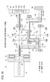
 wheel speed sensors 32A and 32B, the rotation speeds of the first and second electric motors 22A and 22B acquired from the resolvers 36A and 36B, the ECU 26 described above is operated by steering. Angle, accelerator pedal opening AP, shift position, SOC of battery 24 (also referred to as a charged amount or remaining capacity, usually expressed as a percentage in which the full charge capacity is 100%), various oil temperatures The ECU 26 receives a signal for controlling the front wheel drive device 16 including the internal combustion engine 12 and the electric motor 14, a signal for controlling the rear wheel drive device 20 including the first and second electric motors 22A and 22B, and the like. Is output.

[前輪駆動装置16の説明]
図2は、前輪駆動装置16の概略構成を示している。前輪駆動装置16の詳細な構成は、例えば、特許文献4の図1、図14等に開示されているので、ここでは、煩雑さの回避と理解の便宜のために、この発明を理解できる程度に説明する。
[Description of Front Wheel Drive Device 16]
FIG. 2 shows a schematic configuration of the front wheel drive device 16. The detailed configuration of the front wheel drive device 16 is disclosed in, for example, FIG. 1 and FIG. 14 of Patent Document 4, so that the present invention can be understood to avoid complexity and for the convenience of understanding. Explained.

前輪駆動装置16は、駆動源である内燃機関12と、駆動源、駆動補助源又は発電機として機能する電動機14と、駆動源、駆動補助源の動力を前輪Wfに伝達するための変速機18と、変速機18の一部を構成する差動式減速機としての遊星歯車機構52と、を備えている。   The front wheel drive device 16 includes an internal combustion engine 12 as a drive source, an electric motor 14 that functions as a drive source, a drive assist source, or a generator, and a transmission 18 for transmitting the power of the drive source and the drive assist source to the front wheels Wf. And a planetary gear mechanism 52 as a differential reduction gear constituting a part of the transmission 18.

電動機14は、3相ブラシレス同期モータでありステータコアにコイルが巻回されたステータ56と、このステータ56に対向するように配置された永久磁石が組み込まれたロータ58とを有している。   The electric motor 14 is a three-phase brushless synchronous motor, and includes a stator 56 in which a coil is wound around a stator core, and a rotor 58 in which a permanent magnet arranged to face the stator 56 is incorporated.

遊星歯車機構52は、リングギヤ52aと、プラネタリギヤ52cと、プラネタリキャリヤ52dと、ロータ58に連結されたサンギヤ52bと、を有している。   The planetary gear mechanism 52 includes a ring gear 52 a, a planetary gear 52 c, a planetary carrier 52 d, and a sun gear 52 b connected to the rotor 58.

変速機18は、内燃機関12のクランク軸54に設けられた第1クラッチ61(第1断接手段)及び第2クラッチ62(第2断接手段)と、遊星歯車機構52を含む複数の変速ギヤ群と、これら変速ギヤ群を切り替える(変速段を切り替える)第1変速アクチュエータ(第1変速手段、第1変速シフタ・シンクロナイザ)41及び第2変速アクチュエータ(第2変速手段、第2変速シフタ・シンクロナイザ)42を備えた、いわゆるダブルクラッチ式の変速機である。   The transmission 18 includes a plurality of shifts including a first clutch 61 (first connecting / disconnecting means) and a second clutch 62 (second connecting / disconnecting means) provided on the crankshaft 54 of the internal combustion engine 12, and a planetary gear mechanism 52. A gear group, a first gear shift actuator (first gear shifter, first gear shifter / synchronizer) 41 and a second gear shift actuator (second gear shifter, second gear shifter This is a so-called double-clutch transmission including a synchronizer 42.

変速機18は、内燃機関12のクランク軸54と同軸上に配置され内燃機関12からの動力が第1クラッチ61を介して直接的に伝達される第1主軸(第1の第1主軸ともいう。)101、及び内燃機関12からの動力が前記第1主軸101、サンギヤ52b、プラネタリギヤ52c、及びプラネタリキャリヤ52dを介して伝達される中空状の連結軸103(第2の第1主軸103ともいう。)を備えると共に、内燃機関12からの動力が第2クラッチ62を介して伝達される中空状の第2主軸(第1の第2主軸ともいう。)102と、この第2主軸102に連結されるアイドルギヤ列84(アイドル駆動ギヤ81、第1アイドル従動ギヤ82、及び第2アイドル従動ギヤ83からなる。)と、第2アイドル従動ギヤ83の回転軸としての第2主軸(第2の第2主軸、中間軸ともいう。)105と、を備え、さらに、第1主軸101、103及び第2主軸102、105に対して平行に配置され、差動ギヤ機構95を通じ車軸50A(50B)を介して前輪Wfを駆動するカウンタ軸(出力軸ともいう。)104と、を備えている。   The transmission 18 is disposed coaxially with the crankshaft 54 of the internal combustion engine 12, and is a first main shaft (also referred to as a first first main shaft) to which power from the internal combustion engine 12 is directly transmitted via the first clutch 61. .) 101 and a hollow connecting shaft 103 (also referred to as a second first main shaft 103) to which power from the internal combustion engine 12 is transmitted through the first main shaft 101, the sun gear 52b, the planetary gear 52c, and the planetary carrier 52d. ) And a hollow second main shaft (also referred to as a first second main shaft) 102 to which power from the internal combustion engine 12 is transmitted via the second clutch 62, and the second main shaft 102. Idle gear train 84 (consisting of an idle drive gear 81, a first idle driven gear 82, and a second idle driven gear 83) and a rotation shaft of the second idle driven gear 83. Two main shafts (also referred to as a second second main shaft and an intermediate shaft) 105, and arranged in parallel to the first main shafts 101 and 103 and the second main shafts 102 and 105, and a differential gear mechanism 95. And a counter shaft (also referred to as an output shaft) 104 that drives the front wheels Wf through the axle 50A (50B).

さらに、変速機18には、2つの変速軸の一方の変速軸(奇数段変速軸)である第1及び第2の第1主軸101、103(第1入力軸)上に第5速用駆動ギヤ75と第7速用駆動ギヤ77と第3速用駆動ギヤ73とからなる奇数段ギヤ群(第1ギヤ群)が設けられ、他方の変速軸(偶数段変速軸)である第1及び第2の第2主軸102、105(第2入力軸)上に第2速用駆動ギヤ72と第4速用駆動ギヤ74と第6速用駆動ギヤ76からなる偶数段ギヤ群(第2ギヤ群)が設けられる。   Further, the transmission 18 has a fifth speed drive on the first and second first main shafts 101 and 103 (first input shaft), which is one of the two transmission shafts (odd speed transmission shaft). An odd-numbered gear group (first gear group) composed of a gear 75, a seventh-speed drive gear 77, and a third-speed drive gear 73 is provided, and the other transmission shaft (even-numbered transmission shaft) is the first and On the second second main shafts 102 and 105 (second input shaft), an even-numbered gear group (second gear) composed of the second speed drive gear 72, the fourth speed drive gear 74, and the sixth speed drive gear 76 is provided. Group) is provided.

ここで、第1変速アクチュエータ41は、第1主軸101、103に固定されていない(図2では便宜的に固定されているように図示している。)第5速用駆動ギヤ75と第7速用駆動ギヤ77と第3速用駆動ギヤ73とを選択的に第1主軸101、103に連結乃至解放する。   Here, the first speed change actuator 41 is not fixed to the first main shafts 101 and 103 (shown as being fixed for convenience in FIG. 2) and the fifth speed drive gear 75 and the seventh. The speed driving gear 77 and the third speed driving gear 73 are selectively connected to or released from the first main shafts 101 and 103.

第2変速アクチュエータ42は、第2主軸105に固定されていない(図2では便宜的に固定されているように図示している。)第4速用駆動ギヤ74と第6速用駆動ギヤ76と第2速用駆動ギヤ72を選択的に第2主軸105に連結乃至解放する。   The second speed change actuator 42 is not fixed to the second main shaft 105 (shown as being fixed for convenience in FIG. 2). The fourth speed drive gear 74 and the sixth speed drive gear 76 are shown. The second speed drive gear 72 is selectively connected to or released from the second main shaft 105.

カウンタ軸104に設けられた第1共用従動ギヤ91は、第3速用駆動ギヤ73と噛合し第3速用駆動ギヤ73と共に第3速用ギヤ対73pを構成する一方、第2速用駆動ギヤ72と噛合し第2速用駆動ギヤ72と共に第2速用ギヤ対72pを構成する。   The first shared driven gear 91 provided on the countershaft 104 meshes with the third speed drive gear 73 and constitutes a third speed gear pair 73p together with the third speed drive gear 73, while the second speed drive. The gear 72 is meshed with the second speed drive gear 72 to form a second speed gear pair 72p.

カウンタ軸104に設けられた第2共用従動ギヤ92は、第5速用駆動ギヤ75と噛合し第5速用駆動ギヤ75と共に第5速用ギヤ対75pを構成する一方、第4速用駆動ギヤ74と噛合し第4速用駆動ギヤ74と共に第4速用ギヤ対74pを構成する。   The second shared driven gear 92 provided on the counter shaft 104 meshes with the fifth speed drive gear 75 to form a fifth speed gear pair 75p together with the fifth speed drive gear 75, while the fourth speed drive. The gear 74 is engaged with the fourth speed drive gear 74 to form a fourth speed gear pair 74p.

カウンタ軸104に設けられた第3共用従動ギヤ93は、第7速用駆動ギヤ77と噛合し第7速用駆動ギヤ77と共に第7速用ギヤ対77pを構成する一方、第6速用駆動ギヤ76と噛合して第6速用駆動ギヤ76と共に第6速用ギヤ対76pを構成する。   The third common driven gear 93 provided on the counter shaft 104 meshes with the seventh speed drive gear 77 to form the seventh speed gear pair 77p together with the seventh speed drive gear 77, while the sixth speed drive gear 77 A sixth speed gear pair 76p is configured together with the sixth speed drive gear 76 by meshing with the gear 76.

内燃機関12は、ECU26が第1クラッチ61を締結したときに変速機18の奇数段変速軸である第1主軸101に接続されると共に、第1主軸101を通じて電動機14のロータ58に接続され、電動機14を発電機として駆動することができるようになっている。   The internal combustion engine 12 is connected to the first main shaft 101 that is an odd-speed transmission shaft of the transmission 18 when the ECU 26 engages the first clutch 61, and is connected to the rotor 58 of the electric motor 14 through the first main shaft 101, The electric motor 14 can be driven as a generator.

内燃機関12は、また、電動機14を発電機として駆動しているときに、3、5、7速ギヤ(第3速用駆動ギヤ73、第5速用駆動ギヤ75、第7速用駆動ギヤ77)のいずれかを用いて、カウンタ軸104を通じて前輪Wfに対するトルク伝達を行う。   The internal combustion engine 12 is also driven by the third, fifth, and seventh speed gears (the third speed drive gear 73, the fifth speed drive gear 75, and the seventh speed drive gear when the motor 14 is driven as a generator. 77), torque transmission to the front wheel Wf is performed through the counter shaft 104.

内燃機関12は、さらに、ECU26が第2クラッチ62を締結したときに変速機18の偶数段変速軸である第1及び第2の第2主軸102、105に接続され、2、4、6速ギヤ(第2速用駆動ギヤ72、第4速用駆動ギヤ74、第6速用駆動ギヤ76)のいずれかを用いて、カウンタ軸104を通じて前輪Wfに対するトルク伝達を行う。   The internal combustion engine 12 is further connected to the first and second second main shafts 102 and 105 which are even-stage transmission shafts of the transmission 18 when the ECU 26 engages the second clutch 62, and is connected to the second, fourth and sixth speeds. Torque is transmitted to the front wheels Wf through the counter shaft 104 using any of the gears (second speed drive gear 72, fourth speed drive gear 74, and sixth speed drive gear 76).

一方、ECU26が第1及び第2クラッチ61、62を解放したときに電動機14を電動機として動作させると、ロータ58の回転駆動力が、遊星歯車機構52を通じて、変速機18の奇数段変速軸である第1の第1主軸101に接続され、3、5、7速ギヤ(第3速用駆動ギヤ73、第5速用駆動ギヤ75、第7速用駆動ギヤ77)のいずれかを用いて、カウンタ軸104を通じて前輪Wfに対するトルク伝達を行うことが可能になっている。なお、電動機14が、前輪Wfにトルク伝達を行うときと、前輪Wfから電力回生を行うときには、第1及び第2クラッチ61、62を両方とも解放して内燃機関12との機械的な接続を遮断すると効率がよい。   On the other hand, when the electric motor 14 is operated as an electric motor when the ECU 26 releases the first and second clutches 61, 62, the rotational driving force of the rotor 58 passes through the planetary gear mechanism 52 on the odd-numbered speed change shaft of the transmission 18. It is connected to a certain first first main shaft 101 and uses any of 3, 5, and 7 speed gears (a 3rd speed drive gear 73, a 5th speed drive gear 75, and a 7th speed drive gear 77). The torque can be transmitted to the front wheel Wf through the counter shaft 104. When the motor 14 transmits torque to the front wheels Wf and regenerates power from the front wheels Wf, both the first and second clutches 61 and 62 are released to establish mechanical connection with the internal combustion engine 12. It is efficient when shut off.

カウンタ軸104に設けられたファイナルギヤ94は、奇数段の第3速用、第5速用、第7速用駆動ギヤ73、75、77と偶数段の第2速用、第4速用、第6速用駆動ギヤ72、74、76とで共用している。   The final gear 94 provided on the countershaft 104 is for odd-numbered third speed, fifth-speed, seventh-speed drive gears 73, 75, 77 and even-numbered second speed, fourth speed, It is shared by the sixth-speed drive gears 72, 74, and 76.

この実施形態では、煩雑さの回避のために、遊星歯車機構52を操作する第1速段の変速制御を含めて第1変速アクチュエータ41により奇数段の変速が制御されるものとしている。   In this embodiment, in order to avoid complexity, odd-numbered gear shifts are controlled by the first gear-shift actuator 41 including the first gear shift control for operating the planetary gear mechanism 52.

電動機14のロータ58は、1速のサンギヤ52bに直結されており、内燃機関12の動力に対するアシストは、奇数段側から行われる。つまり、偶数段使用時(第2クラッチ62の締結時)は、奇数段側の第1クラッチ61は解放されているから第1速用駆動ギヤ(遊星歯車機構52と第3速用駆動ギヤ73)、第5速用駆動ギヤ75、及び第7速用駆動ギヤ77を使用したアシスト(動力伝達)が可能になる。   The rotor 58 of the electric motor 14 is directly connected to the first-speed sun gear 52b, and assist for the power of the internal combustion engine 12 is performed from the odd-numbered stage side. That is, when the even-numbered gear is used (when the second clutch 62 is engaged), the first-speed drive gear (the planetary gear mechanism 52 and the third-speed drive gear 73 is released) because the odd-numbered first clutch 61 is released. ), Assist (power transmission) using the fifth speed drive gear 75 and the seventh speed drive gear 77 becomes possible.

回生発電や電動機走行(EV走行)の際には、第1及び第2クラッチ61、62は切断され、内燃機関12は完全に切り離されるが、電動機14の動力伝達は、奇数段ギヤからしか行えないので、回生発電と電動機走行は、奇数段速でのみ行われる。なお、発進は、原則として奇数段速(通常、発進は第1速用駆動ギヤ)でのみ可能になっている。   During regenerative power generation or electric motor travel (EV travel), the first and second clutches 61 and 62 are disconnected and the internal combustion engine 12 is completely disconnected. However, the power transmission of the motor 14 can be performed only from odd-numbered gears. Therefore, regenerative power generation and motor running are performed only at odd speeds. In principle, the vehicle can be started only at an odd speed (normally, the vehicle is started at the first speed drive gear).

このように構成されるダブルクラッチの変速機18では、第1及び第2変速アクチュエータ41、42により次の低速段側の又は高速段側の変速ギヤを予め待機(セット)しておいて、いわゆるプレシフト状態にしておいて、第1及び第2クラッチ61、62を交互につなぐ(断接する、締結乃至解放する)ことで高速な変速を実現している。   In the double-clutch transmission 18 configured in this way, the first and second speed change actuators 41 and 42 wait in advance (set) the next low speed stage side or high speed stage side shift gear, so-called. In the pre-shift state, the first and second clutches 61 and 62 are alternately connected (connected / disengaged, engaged / released) to achieve a high speed shift.

[モータトラクション制御]
ECU26は、各車両状態に合わせて前輪駆動装置16及び後輪駆動装置20を制御している。特に後輪駆動装置20に対しては、後輪Wrの車輪回転数又は第1及び第2電動機22A、22Bのモータ回転数に基づいて後輪Wrのスリップを抑制するモータトラクション制御を行うモータトラクション制御システム(M−TCS)を有する電動機制御装置としても機能し、モータトラクション制御を実行する際に、第1及び第2電動機22A、22Bが発生するトルクを制御し、左右後輪LWr、RWrの回転状態等を制御する。
[Motor traction control]
The ECU 26 controls the front wheel drive device 16 and the rear wheel drive device 20 in accordance with each vehicle state. In particular, for the rear wheel drive device 20, motor traction that performs motor traction control that suppresses slip of the rear wheel Wr based on the wheel rotation speed of the rear wheel Wr or the motor rotation speed of the first and second electric motors 22A and 22B. It also functions as an electric motor control device having a control system (M-TCS), and controls the torque generated by the first and second electric motors 22A and 22B when executing motor traction control, and controls the left and right rear wheels LWr and RWr. Control the rotation state and so on.

[電動機の不要な減速トルクの発生防止動作及びバッテリ保護動作]
次に、モータトラクション制御システムが動作状態となっている車両10の後輪Wrが第1及び第2電動機22A、22Bを含む後輪駆動装置20により駆動され、且つ内燃機関12の動力により電動機14を発電機として動作させると共に前輪Wfが前輪駆動装置16により駆動されている全輪駆動状態を例として、この発明の要部に係る第1及び第2電動機22A、22Bでの不要な減速トルクの発生の防止動作及びバッテリ24に対するECU26による保護動作について、図3の車両10の電力分配図の模式的ブロック図、図4のバッテリ保護の説明図及び図5のタイムチャート並びに図6、図7のフローチャート等を参照して説明する。
[Operation to prevent unnecessary deceleration torque from the motor and battery protection]
Next, the rear wheel Wr of the vehicle 10 in which the motor traction control system is in an operating state is driven by the rear wheel drive device 20 including the first and second electric motors 22A and 22B, and the electric motor 14 is driven by the power of the internal combustion engine 12. As an example of the all-wheel drive state in which the front wheel Wf is driven by the front wheel drive device 16 while operating as a generator, unnecessary deceleration torque of the first and second electric motors 22A and 22B according to the main part of the present invention 3, a schematic block diagram of the power distribution diagram of the vehicle 10 in FIG. 3, an explanatory diagram of battery protection in FIG. 4, a time chart in FIG. 5, and FIGS. 6 and 7. This will be described with reference to a flowchart and the like.

図3において、車両10の内燃機関12(ENGと説明)に対して電動機14{前輪Wf側の電動機であるので、図3中、Fr−MOT(前輪駆動電動機)と説明}が上述したダブルクラッチ式の変速機18を通じて接続され、発電機として動作している電動機14のある時点(図5中、時点t1まで)での発電電力PgenがPgen=X[kW]であるものとする。   In FIG. 3, the double clutch described above with respect to the internal combustion engine 12 (denoted as ENG) of the vehicle 10 is the electric motor 14 {the front wheel Wf side electric motor, and therefore, Fr-MOT (front wheel drive motor) in FIG. It is assumed that the generated power Pgen at a certain time (up to time t1 in FIG. 5) of the electric motor 14 connected through the transmission 18 and operating as a generator is Pgen = X [kW].

図3、図4において、バッテリ24のバッテリ電力Pbat[kW](流出電力−Pd、流入電力Pc)は、バッテリ24からの流出電力−Pd[kW]が、流出電力−Pd=0[kW]の動作点214(定常状態の動作点ともいう。)で動作しているものとする。バッテリ電力Pbat[kW]は、放電側を負、充電側を正に採っている。従って、バッテリ24の流出電力−Pdは放電電力を表し、流入電力Pcは充電電力を表している。   3 and 4, the battery power Pbat [kW] (outflow power -Pd, inflow power Pc) of the battery 24 is the outflow power -Pd [kW] from the battery 24, and the outflow power -Pd = 0 [kW]. The operation point 214 (also referred to as a steady-state operation point) is assumed to be operating. The battery power Pbat [kW] is negative on the discharge side and positive on the charge side. Therefore, the outflow power -Pd of the battery 24 represents discharge power, and the inflow power Pc represents charge power.

図3において、左後輪LWrを駆動する第1電動機22A{後輪Wr側の電動機であるので、図3中、Rr−MOT(後輪駆動電動機)と説明)}の消費電力Pmot1[kW]と右後輪RWrを駆動する第2電動機22B(Rr−MOT)の消費電力Pmot2との左右合計電力Pmotが、ある時点(図5中、時点t1まで)Pmot=Y[kW](Rr−MOT出力電力ともいう。)であるものとする。   In FIG. 3, the power consumption Pmot1 [kW] of the first electric motor 22A that drives the left rear wheel LWr {represented as Rr-MOT (rear wheel drive motor) in FIG. 3 because it is a motor on the rear wheel Wr side}. And the left and right total power Pmot of the power consumption Pmot2 of the second electric motor 22B (Rr-MOT) driving the right rear wheel RWr is Pmot = Y [kW] (Rr-MOT) at a certain time (until time t1 in FIG. 5). It is also called output power.)

バッテリ24に接続されている空気調和装置等の高圧補機202及びステップダウンコンバータ204を通じて接続されている12Vバッテリ206と低圧補機208からなる補機210の補機負荷電力Pl[kW]の値は、補機負荷電力Pl=L[kW]で、一定であるものとする。   The value of the auxiliary load power Pl [kW] of the auxiliary machine 210 including the 12V battery 206 and the low-voltage auxiliary machine 208 connected through the step-down converter 204 and the high-pressure auxiliary machine 202 such as an air conditioner connected to the battery 24. Is constant with auxiliary load power Pl = L [kW].

図4に示すように、バッテリ24は、SOC[%]に応じた流入出力電力の限界を有しており、特に低温時には、縦軸のバッテリ流出電力最大値−Pdmax[kW]及びバッテリ流入電力最大値Pcmax[kW]といった、横軸のSOC[%]に応じた定格制限値を持っている。   As shown in FIG. 4, the battery 24 has a limit of the inflow output power according to the SOC [%], and particularly when the temperature is low, the battery outflow power maximum value −Pdmax [kW] and the battery inflow power on the vertical axis. It has a rated limit value corresponding to SOC [%] on the horizontal axis, such as a maximum value Pcmax [kW].

蓄電量SOCがSOC=SOC1であるときの定格制限値であるバッテリ流入電力最大値Pcmaxが、Pcmax=Pcth1[kW](許容入力電力という。)であり、バッテリ流出電力最大値−Pdmaxが、−Pdmax=−Pdth1[kW]であるものとする。   The battery inflow power maximum value Pcmax, which is a rated limit value when the storage amount SOC is SOC = SOC1, is Pcmax = Pcth1 [kW] (referred to as allowable input power), and the battery outflow power maximum value −Pdmax is − It is assumed that Pdmax = −Pdth1 [kW].

図4に示すように、放電可能電力値であるバッテリ流出電力最大値−Pdmaxは、SOC[%]の0[%]から100[%]への増加に応じて0[kW]から絶対値が線形に増加し、充電可能電力値であるバッテリ流入電力最大値Pcmax[kW]は、SOC[%]の100[%]から0[%]への減少に応じて0[kW]から絶対値が線形に増加する特性になっている。   As shown in FIG. 4, the battery outflow power maximum value −Pdmax, which is a dischargeable power value, has an absolute value from 0 [kW] as the SOC [%] increases from 0 [%] to 100 [%]. The battery inflow maximum power value Pcmax [kW], which increases linearly and is a chargeable power value, has an absolute value from 0 [kW] according to a decrease in SOC [%] from 100 [%] to 0 [%]. The characteristics increase linearly.

なお、実際上、数秒程度の短時間であれば、この定格制限値(連続定格制限値)を上回る(−Pdmaxより放電電力を大きく、Pcmaxよりも充電電力を大きく)使用も可能な場合がある(短時間定格制限値)。   In practice, if it is a short time of about several seconds, it may be possible to use it exceeding the rated limit value (continuous rated limit value) (the discharge power is larger than −Pdmax and the charge power is larger than Pcmax). (Short-time rated limit).

図4に示すように、蓄電量SOC[%]がSOC=SOC1[%]で、バッテリ24の動作点214の定常状態でのバッテリ電力Pbat[kW]をPbat=0[kW]としているので、その定常状態においては、第1及び第2電動機22A、22Bが消費する左右合計電力Pmot=Yと補機負荷電力Pl=L[kW]との合成電力である負荷消費電力Ps(Ps=Pmot+Pl)が、次の(1)〜(3)式に示すように、発電機として動作している電動機14の発電電力Pgen=X[kW]に等しい値となっている。
定常状態:Pgen=Ps=Pmot+Pl …(1)
定常状態:X=Y+L …(2)
定常状態:SOC=SOC1、Pbat=0 …(3)
As shown in FIG. 4, since the storage amount SOC [%] is SOC = SOC1 [%] and the battery power Pbat [kW] in the steady state of the operating point 214 of the battery 24 is Pbat = 0 [kW], In the steady state, load power consumption Ps (Ps = Pmot + Pl), which is a combined power of the left and right total power Pmot = Y consumed by the first and second motors 22A and 22B and the auxiliary load power Pl = L [kW]. However, as shown in the following formulas (1) to (3), the generated electric power Pgen of the electric motor 14 operating as a generator is a value equal to X [kW].
Steady state: Pgen = Ps = Pmot + Pl (1)
Steady state: X = Y + L (2)
Steady state: SOC = SOC1, Pbat = 0 (3)

この定常状態制御中において、バッテリ24の過放電保護のために、流出電力−Pdが上回ってはいけない放電閾値電力(バッテリ流出電力最大値)−Pdmax[kW]は、図4に示すように、閾値電力−Pdth1[kW]になる。なお、バッテリ24の過充電保護のために、バッテリ24への流入電力Pcが上回ってはいけない充電閾値電力(バッテリ流入電力最大値)Pcmax[kW]は、閾値電力Pcth1[kW]になる。   During the steady state control, the discharge threshold power (battery outflow power maximum value) -Pdmax [kW] that should not exceed the outflow power -Pd for overdischarge protection of the battery 24 is as shown in FIG. The threshold power is −Pdth1 [kW]. For overcharge protection of the battery 24, the charging threshold power (battery inflow power maximum value) Pcmax [kW] that should not exceed the inflow power Pc to the battery 24 becomes the threshold power Pcth1 [kW].

そこで、図6中、ステップS1の時点t1(図5参照)以前のECU26よる定常状態の制御中においては、例えば、変速機18の変速段が第4速変速段で平坦路を定速走行中であるものとする。   Therefore, in FIG. 6, during steady state control by the ECU 26 before time t1 (see FIG. 5) in step S1, for example, the gear stage of the transmission 18 is running at a constant speed on a flat road at the fourth speed gear stage. Suppose that

この定常状態制御中の定速走行中では、上述したように、駆動力(トルク)を発生している第1及び第2電動機22A、22Bのトラクション用の左右合計電力Pmot=Y及び補機210の補機負荷電力Pl=Lは、発電機として駆動されている電動機14の発電電力Pgen=Xによって賄われているので、バッテリ24のバッテリ電力Pbatが0[kW]になっている。   During the constant speed running during the steady state control, as described above, the left and right total power Pmot = Y for the traction of the first and second electric motors 22A and 22B generating the driving force (torque) and the auxiliary device 210. Since the auxiliary load power Pl = L is covered by the generated power Pgen = X of the electric motor 14 driven as a generator, the battery power Pbat of the battery 24 is 0 [kW].

図8に示すように、時点t1以前の第4速変速段での定常状態(以下、第4速走行状態ともいう。)の制御中においては、第2クラッチ62が締結され、内燃機関12から第1の第2主軸102を介し第4速用駆動ギヤ74を通じて前輪Wfが駆動される一方、第5速用駆動ギヤ75を介して第1の第1主軸101と一体に形成されたロータ58が回転され、電動機14が発電電力Pgen=Xを発電している。図8において、ハッチングを施した矢印は、エンジン駆動経路(内燃機関12による前輪Wfの駆動経路)を示し、白抜きの矢印は、モータ発電経路(内燃機関12によりロータ58を回転して電動機14を発電させる経路)を示している。   As shown in FIG. 8, during the control in the steady state (hereinafter also referred to as the fourth speed traveling state) at the fourth speed gear stage before time t1, the second clutch 62 is engaged and the internal combustion engine 12 The front wheel Wf is driven through the fourth speed drive gear 74 via the first second main shaft 102, while the rotor 58 is formed integrally with the first first main shaft 101 via the fifth speed drive gear 75. Is rotated, and the electric motor 14 generates the generated power Pgen = X. In FIG. 8, hatched arrows indicate engine drive paths (drive paths of the front wheels Wf by the internal combustion engine 12), and white arrows indicate motor power generation paths (rotors 58 rotated by the internal combustion engine 12 to rotate the motor 14. The power generation path) is shown.

ちなみに、図8の状態(第4速走行状態、第5速用駆動ギヤ75による電動機14の発電状態)において、例えば、車速を上げるためにアクセルペダルが踏み込まれたことがECU26により検出されると、ECU26は、次に変速予定の第5速用駆動ギヤ75を、第1の第1主軸101と一体回転状態、換言すれば5速シンクロ(不図示)が締結されている状態、いわゆるプレシフトの完了状態にしているので、ECU26は、第2クラッチ62を解放(切断)し、第1クラッチ61を締結する操作(第1及び第2クラッチ61、62の繋ぎ替え操作)を行うと共に、第2変速アクチュエータ42を通じて第4速用駆動ギヤ74を第2の第2主軸105から解放する。   Incidentally, when the ECU 26 detects, for example, that the accelerator pedal is depressed to increase the vehicle speed in the state of FIG. 8 (the fourth speed traveling state, the power generation state of the electric motor 14 by the fifth speed driving gear 75). The ECU 26 rotates the fifth-speed drive gear 75 to be shifted next with the first first main shaft 101, in other words, with a fifth-speed sync (not shown) fastened, so-called pre-shift. Since the ECU 26 is in the completed state, the ECU 26 releases (disconnects) the second clutch 62 and engages the first clutch 61 (replacement operation of the first and second clutches 61 and 62). The fourth speed drive gear 74 is released from the second second main shaft 105 through the speed change actuator 42.

これにより、図9に示すように、変速機18を第4速走行状態から第5速走行状態に瞬時に切り替えることができ、内燃機関12から第1の第1主軸101を介し第5速用駆動ギヤ75を通じての前輪Wfの駆動(ハッチングを施した矢印参照)、並びに第1の第1主軸101の回転(第5速用駆動ギヤ75も回転)駆動による電動機14の発電状態(白抜きの矢印)に遷移させることができる。   As a result, as shown in FIG. 9, the transmission 18 can be instantaneously switched from the fourth speed traveling state to the fifth speed traveling state, and for the fifth speed from the internal combustion engine 12 via the first first main shaft 101. The power generation state of the motor 14 by the driving of the front wheel Wf through the driving gear 75 (see the hatched arrow) and the rotation of the first first main shaft 101 (the fifth speed driving gear 75 also rotates) (Arrow).

図8に示した第4速走行状態(第5速用駆動ギヤ75で発電)の制御中に戻り、ステップS2にて奇数段ギヤの架け替えが発生するか否かの可能性が判定される。   Returning to the control during the fourth speed running state (power generation by the fifth speed drive gear 75) shown in FIG. 8, it is determined in step S2 whether or not odd-numbered gear replacement occurs. .

上述したように、図8に示した第4変速段時で第5速用駆動ギヤ75での発電中に、図9に示した第5変速段への変速操作を必要と判定した場合には、奇数段ギヤの架け替えは発生しない(奇数段ギヤは、第5速用駆動ギヤ75と変わりはない)ので、ステップS2の判定は否定的(ステップS2:NO)とされ、ステップS1の定常状態の制御に戻る。   As described above, when it is determined that the shift operation to the fifth gear shown in FIG. 9 is necessary during the power generation by the fifth speed drive gear 75 at the fourth gear shown in FIG. Since the odd-numbered gear is not replaced (the odd-numbered gear is not different from the fifth-speed drive gear 75), the determination in step S2 is negative (step S2: NO), and the steady state of step S1. Return to state control.

しかし、時点t1にて、例えば、上り坂にさしかかり運転者によるアクセルペダルの踏み込みが開始され、あるいはクルーズコントロール(定速走行制御)中に上り坂にさしかかりECU26によるスロットル開度の増加が開始され、第4変速段での走行から第5変速段での走行ではなく第3変速段での走行への変更がECU26により予測されたとき、ECU26により、現時点では、発電に寄与している第5速用駆動ギヤ75を第3速用駆動ギヤ73に架け替える奇数段ギヤ架け替え発生可能性の判定が肯定的とされる(ステップS2:YES)。   However, at time t1, for example, the driver starts to depress the accelerator pedal, or the driver begins to depress the accelerator pedal during the cruise control (constant speed running control), and the ECU 26 starts increasing the throttle opening. When the ECU 26 predicts a change from traveling at the fourth speed to traveling at the third speed instead of traveling at the fifth speed, the ECU 26 at the fifth speed currently contributing to power generation is predicted. The determination of the possibility of occurrence of odd-numbered gear replacement that replaces the driving gear 75 with the third-speed driving gear 73 is affirmative (step S2: YES).

このとき、時点t1のステップS3にて、ECU26は、図5に示すように、奇数段ギヤ架け替えフラグFodcをセットする(フラグを立てる)。   At this time, in step S3 at time t1, the ECU 26 sets an odd-stage gear change flag Fodc (sets a flag) as shown in FIG.

次いで、ECU26は、第4変速段から第3変速段にギヤを円滑に切り替えるために、5速シンクロ(不図示)が第5速用駆動ギヤ75に締結されている状態から3速シンクロ(不図示)が第3速用駆動ギヤ73に締結されている状態にプレシフトする操作を時点t1〜t5の間で行う。   Next, in order to smoothly switch the gear from the fourth shift speed to the third shift speed, the ECU 26 changes from the state in which the fifth speed sync (not shown) is fastened to the fifth speed drive gear 75 to the third speed sync (not shown). (Not shown) is pre-shifted to the state of being fastened to the third speed drive gear 73 between time t1 and time t5.

この場合、まず、時点t1〜t2の間、ステップS4にて、内燃機関12の動力により発電機として動作している電動機14の発電量を減少させる発電量減少制御及び第1及び第2電動機22A、22Bの駆動力を減少させる電動機駆動力減少制御を行う。   In this case, first, between time points t1 and t2, in step S4, the power generation amount reduction control for reducing the power generation amount of the motor 14 operating as a generator by the power of the internal combustion engine 12, and the first and second motors 22A. , 22B to reduce the driving force of the motor.

発電量減少制御は、ECU26が、電動機14に電気的に接続されているインバータ15{ここでは、ロータ58の回転により発生する交流電力を直流電力に変換している。}のオンデューティを徐々に小さくすることで、電動機14の発電電力Pgenを、発電電力Xから徐々に小さくしていく。この発電電力Xからの発電電力Pgenの減少と共に、この発電電力Pgenの減少に対応させて第1及び第2電動機22A、22Bの駆動力(駆動トルク)を徐々に低下させる電動機駆動力減少制御を行う。   In the power generation amount reduction control, the ECU 26 converts the AC power generated by the rotation of the rotor 58 into DC power in the inverter 15 electrically connected to the motor 14. }, The generated power Pgen of the electric motor 14 is gradually reduced from the generated power X. Along with the decrease in the generated power Pgen from the generated power X, the motor driving force reduction control for gradually decreasing the driving force (driving torque) of the first and second motors 22A and 22B in response to the decrease in the generated power Pgen. Do.

このようにして、時点t1〜t2間では、発電電力Pgenの減少に応じて第1及び第2電動機22A、22Bの左右合計電力Pmotが徐々に低下する。このため、時点t1〜t2間では、負荷消費電力Ps=Pmot+Plが徐々に低下する。   Thus, between the time points t1 and t2, the left and right total power Pmot of the first and second electric motors 22A and 22B gradually decreases in accordance with the decrease in the generated power Pgen. For this reason, the load power consumption Ps = Pmot + Pl gradually decreases between the time points t1 and t2.

なお、公知のように、電動機の駆動力をP[W]としたとき、前記電動機の駆動力P[W]とトルクT[Nm]との関係は、前記電動機の回転数をn[rpm]として、“P=2・π・T・n”の式で与えられる線形な関係にある。   As is well known, when the driving force of the motor is P [W], the relationship between the driving force P [W] of the motor and the torque T [Nm] indicates that the rotational speed of the motor is n [rpm]. As a linear relationship given by the equation “P = 2 · π · T · n”.

ECU26は、時点t1以降、ステップS5にて、負荷消費電力Psが発電電力Pgenにより賄いきれない発電電力Pgenの不足状態(|Ps|≧|Pgen|)に達するか否かを判定する。   After time t1, the ECU 26 determines in step S5 whether or not the load power consumption Ps reaches a shortage state (| Ps | ≧ | Pgen |) of the generated power Pgen that cannot be covered by the generated power Pgen.

賄えているとき(ステップS5:NO)には、ステップS4の制御を継続する。   When it is covered (step S5: NO), the control in step S4 is continued.

時点t1から発電電力Pgenと左右合計電力Pmotが減少中に、時点t2にて、左右合計電力Pmotの電力[kW]が、0[Nm]相当の電力になる。   While the generated power Pgen and the left and right total power Pmot are decreasing from time t1, the power [kW] of the left and right total power Pmot becomes power equivalent to 0 [Nm] at time t2.

そして、時点t2以降、減少中の発電電力Pgenでは、負荷消費電力Psを賄いきれない状態になると(ステップS5:YES)、その不足分に応じた分のバッテリ電力Pbatの流出電力−Pd(図5参照)が、時点t2以降徐々に増加する。   Then, if the generated power Pgen that is decreasing after the time point t2 cannot cover the load power consumption Ps (step S5: YES), the outflow power -Pd of the battery power Pbat corresponding to the shortage (FIG. 5). 5) gradually increases after time t2.

この時点t2以降、左右合計電力Pmotの電力が0[Nm]よりも小さくなると、第1及び第2電動機22A、22Bで発生する減速トルク(負のトルク)が、後輪Wrに対して制動力として反映されてしまい、乗員が、“引き摺り感”を感じる場合がある。   After this time t2, when the electric power of the left and right total electric power Pmot becomes smaller than 0 [Nm], the deceleration torque (negative torque) generated in the first and second electric motors 22A and 22B is applied to the rear wheel Wr as a braking force. As a result, the occupant may feel a “smooth feeling”.

この“引き摺り感”の発生を回避するために、ステップS6にて、第1及び第2電動機22A、22Bが減速トルクを発生しない、それぞれゼロトルク状態とする0[Nm]制御を、次のステップS7の判定処理が否定的(ステップS7:NO、|−Pd|<|−Pdth1|)になっている期間実行する{0[Nm]制御を開始することで、ステップS4で開始した電動機駆動力減少制御(時点t1〜t2)が停止される。}。   In order to avoid the occurrence of the “drag feeling”, in step S6, the first and second electric motors 22A and 22B do not generate deceleration torque, and 0 [Nm] control is set to the zero torque state in the next step S7. The motor driving force reduction started in step S4 is started by starting {0 [Nm] control executed during a period in which the determination process is negative (step S7: NO, | −Pd | <| −Pdth1 |) Control (time t1 to t2) is stopped. }.

ステップS7の判定処理では、図4に示したバッテリ電力Pbatの流出電力−Pdが、現在の動作点SOC1(実際には、時点t2以降徐々に低下する。)での“バッテリ流出電力最大値(−Pdmax)=閾値電力(−Pdth1)[kW](制限値)”になる(−Pd=−Pdth1)か、否かを判定する。   In the determination process of step S7, the outflow power -Pd of the battery power Pbat shown in FIG. 4 is “the maximum battery outflow power value (in practice, gradually decreases after time t2)”. It is determined whether or not (−Pdmax) = threshold power (−Pdth1) [kW] (limit value) ”(−Pd = −Pdth1).

ステップS7:NO及びステップS6の処理を繰り返す0[Nm]制御を行っているときに、時点t3に示すように、バッテリ24からの流出電力−Pdが、閾値電力−Pdth1[kW]を上回ること(|Pbat|>|−Pdth1|)を予側あるいは取得(検出)したとき(ステップS7:YES、−Pd=−Pdth1)には、バッテリ24が過放電して劣化する可能性を防止してバッテリ24を保護するために、時点t3のステップS8にて、0[kW]制御実施中フラグF0をセットし(立て)、第1及び第2電動機22A、22Bの左右合計電力Pmotを0[kW](Pmot=0[kW])にする0[kW]制御に切り替える(時点t2で開始した0[Nm]制御を時点t3で停止し、時点t3で0[kW]制御を開始する。)。すなわち、インバータ23A、23Bのオンデューティをゼロ値にし、コンバータとして動作していたインバータ23A、23Bのスイッチング動作を停止する。   Step S7: When performing 0 [Nm] control to repeat the processing of NO and Step S6, the outflow power -Pd from the battery 24 exceeds the threshold power -Pdth1 [kW] as shown at time t3. When (| Pbat |> | -Pdth1 |) is predicted or acquired (detected) (step S7: YES, -Pd = -Pdth1), the battery 24 may be prevented from being overdischarged and deteriorated. In order to protect the battery 24, in step S8 at time point t3, the 0 [kW] control execution flag F0 is set (standing), and the left and right total power Pmot of the first and second electric motors 22A and 22B is set to 0 [kW]. ] (Pmot = 0 [kW]) is switched to 0 [kW] control (0 [Nm] control started at time t2 is stopped at time t3, and 0 [kW] control is started at time t3.) . That is, the on-duty of the inverters 23A and 23B is set to zero, and the switching operation of the inverters 23A and 23B that have been operating as converters is stopped.

このため、時点t3において、時点t3での0[Nm]制御のために費やしていた流出電力−Pdがその分だけ急減し、時点t3以降、時点t4までの間、定電力消費している補機負荷電力Plを確保する分であって、発電電力Pgenの減少分を補う分、バッテリ電力Pbatを徐々に増加させながら、ステップS9にて、発電電力Pgenが略ゼロ値(Pgen≒0)になったか否かを判定する。   For this reason, at time point t3, the outflow power −Pd spent for 0 [Nm] control at time point t3 sharply decreases by that amount, and the constant power consumption from time point t3 to time point t4 is supplemented. In step S9, the generated power Pgen is set to a substantially zero value (Pgen≈0) while the battery power Pbat is gradually increased by the amount that secures the machine load power Pl and compensates for the decrease in the generated power Pgen. It is determined whether or not.

時点t4において、発電電力Pgenが略ゼロ値(Pgen≒0[kW])になったとき(ステップS9:YES)、換言すれば、ステップS4(時点t1)で開始した発電量減少制御が終了したとき、図7のステップS10にて、ECU26による第1変速アクチュエータ41の操作により変速用駆動ギヤ(ここでは、第5速用駆動ギヤ75)の第1の第1主軸101との連結を5速シンクロ(不図示)を解放することで解放する。この操作により、カウンタ軸104に設けられた第2共用従動ギヤ92からの駆動力が第5速用駆動ギヤ75を介して第1の第1主軸101に伝達しないようになる。   When the generated power Pgen becomes substantially zero (Pgen≈0 [kW]) at time t4 (step S9: YES), in other words, the power generation amount reduction control started at step S4 (time t1) is completed. In step S10 of FIG. 7, the ECU 26 operates the first speed change actuator 41 to connect the speed change drive gear (here, the fifth speed drive gear 75) with the first first main shaft 101 to the fifth speed. Release by releasing the synchro (not shown). By this operation, the driving force from the second shared driven gear 92 provided on the counter shaft 104 is not transmitted to the first first main shaft 101 via the fifth speed driving gear 75.

次いで、時点t4以降、時点t5までのステップS11にて、ECU26は、回生方向からオフ状態に切り替えられていたインバータ15を駆動方向に切り替え、バッテリ24のバッテリ電力Pbatにより電動機14を電動機として回転動作させ、第1の第1主軸101の回転数を増加させる。   Next, in step S11 from time t4 to time t5, the ECU 26 switches the inverter 15 that has been switched from the regeneration direction to the off state in the driving direction, and rotates the motor 14 using the battery power Pbat of the battery 24 as the motor. And the number of rotations of the first first spindle 101 is increased.

このようにして、ステップS11にて、第1の第1主軸101の回転数が、架け替え予定の奇数段ギヤである第3速用駆動ギヤ73の所定回転数近傍になるまで増加させる回転数合わせ制御を行う。   In this way, in step S11, the number of rotations to be increased until the number of rotations of the first first main shaft 101 is close to the predetermined number of rotations of the third-speed drive gear 73, which is an odd-stage gear to be replaced. Perform alignment control.

第1の第1主軸101の回転数が第3速用駆動ギヤ73の回転数に増加した時点t5のステップS12にて、ECU26による第1変速アクチュエータ41の操作により、第3速用駆動ギヤ73を第1の第1主軸101と一体回転状態とすべく、両者を3速シンクロ(不図示)にて締結し、インバータ15を回生方向に切り替える。   In step S12 at time t5 when the rotation speed of the first first main shaft 101 is increased to the rotation speed of the third speed drive gear 73, the operation of the first speed change actuator 41 by the ECU 26 causes the third speed drive gear 73 to move. Are fastened together with the first first spindle 101 in a three-speed sync (not shown), and the inverter 15 is switched to the regeneration direction.

このとき、ステップS13にて奇数段ギヤ架け替えフラグFodcをリセットする(下げる)。   At this time, the odd-numbered gear replacement flag Fodc is reset (lowered) in step S13.

ステップS12の操作により図10に示すように、時点t5のステップS14にて、第3速用駆動ギヤ73及び第1の第1主軸101は、第1共用従動ギヤ91を通じてカウンタ軸104の回転駆動力により回転されてプレシフトの完了状態となる一方で、電動機14が発電機として発電を再開する。   As shown in FIG. 10 by the operation of step S12, the third speed drive gear 73 and the first first main shaft 101 are driven to rotate the counter shaft 104 through the first common driven gear 91 at step S14 at time t5. While being rotated by the force to complete the preshift, the electric motor 14 resumes power generation as a generator.

そして、時点t5のステップS14にて、インバータ15のオンデューティの増加制御を行うことで発電電力Pgenが増加中となり、発電電力Pgenが第1及び第2電動機22A、22Bを駆動する左右合計電力Pmotとして利用可能になるので、その分バッテリ24のバッテリ電力Pbatは低下する。   Then, in step S14 at time t5, the on-duty increase control of the inverter 15 is performed so that the generated power Pgen is increasing, and the generated power Pgen drives the first and second electric motors 22A and 22B. Therefore, the battery power Pbat of the battery 24 decreases accordingly.

発電機として機能している電動機14の発電量が、ステップS15にて、第1及び第2電動機22A、22Bを0[Nm]制御可能な発電量に到達するか否かを判定し、0[Nm]に到達した(ステップS15:YES)時点t6のステップS16にて、0[kW]制御実施中フラグF0をリセットし、ステップS8(時点t3)にて開始した0[kW]制御を終了する。   In step S15, it is determined whether or not the power generation amount of the motor 14 functioning as a power generator reaches a power generation amount capable of controlling the first and second motors 22A and 22B to 0 [Nm]. Nm] (step S15: YES) At step t16 at time t6, the 0 [kW] control execution flag F0 is reset, and the 0 [kW] control started at step S8 (time t3) is terminated. .

次いで、時点t6以降のステップS17にて、発電量増加制御を継続し、発電電力Pgenの増加に対応して第1及び第2電動機22A、22Bの左右合計電力Pmotを増加させ、ステップS18にて、発電量が目標駆動力となる目標発電量に達したか否かが判定され、目標発電量に達したときの時点t7にて、図10に示した、第4速走行状態(第3速用駆動ギヤ73で発電)の定常状態制御に入る。   Next, in step S17 after time t6, the power generation amount increase control is continued, and the left and right total power Pmot of the first and second electric motors 22A and 22B is increased corresponding to the increase in the generated power Pgen, and in step S18. Then, it is determined whether or not the power generation amount has reached the target power generation amount as the target driving force. At the time t7 when the target power generation amount is reached, the fourth speed traveling state (third speed) shown in FIG. The steady state control of power generation) is started.

図10に示した第4速走行状態(第3速用駆動ギヤ73による電動機14の発電状態)にて、例えば、上り坂走行中でアクセルペダルが踏み込まれたことがECU26により検出されると、ECU26は、第2クラッチ62を解放(切断)し、第1クラッチ61を締結する操作(第1及び第2クラッチ61、62の繋ぎ替え操作)を行うと共に、第2変速アクチュエータ42を通じて第4速用駆動ギヤ74を第2の第2主軸105から解放する。   In the fourth speed traveling state (the power generation state of the electric motor 14 by the third speed drive gear 73) shown in FIG. 10, for example, when the ECU 26 detects that the accelerator pedal is depressed while traveling uphill, The ECU 26 performs the operation of releasing (disconnecting) the second clutch 62 and fastening the first clutch 61 (operation for changing the connection between the first and second clutches 61 and 62) and the fourth speed through the second speed change actuator 42. The drive gear 74 is released from the second second main shaft 105.

これにより、図11に示すように、変速機18を第4速走行状態から第3速走行状態に瞬時に切り替えることができ、内燃機関12から第1の第1主軸101を介し第3速用駆動ギヤ73を通じての前輪Wfの駆動(ハッチングを施した矢印参照)、並びに第1の第1主軸101の回転(第3速用駆動ギヤ73も回転)駆動による電動機14の発電状態(白抜きの矢印)に遷移させることができる。   As a result, as shown in FIG. 11, the transmission 18 can be instantaneously switched from the fourth speed traveling state to the third speed traveling state, and for the third speed from the internal combustion engine 12 via the first first main shaft 101. The power generation state of the motor 14 by the driving of the front wheel Wf through the driving gear 73 (see the hatched arrow) and the rotation of the first first main shaft 101 (the third speed driving gear 73 also rotates) (Arrow).

[変形例]
図12は、この発明の変形例に係る車両10Aの概略構成を示すブロック図である。図12に示す車両10Aでは、上記実施形態に係る車両10の前輪駆動装置16及び後輪駆動装置20の構成が前後逆になっている。すなわち、車両10Aの前輪駆動装置16aは、車両10Aの前側に配置された左右の前輪Wf(LWf、RWf)を駆動する第1及び第2電動機22A、22Bを備える。また、車両10Aの後輪駆動装置20aは、車両10Aの後ろ側に配置され後輪Wrを駆動する内燃機関12に変速機18を介して直列に接続される電動機14を備える。この車両10Aに対しても、上述した奇数段変速ギヤの架け替え時における、第1及び第2電動機22A、23Aの不要な減速トルクの発生防止動作及びバッテリ24の過放電を防止するバッテリ保護動作を適用することができる。
[Modification]
FIG. 12 is a block diagram showing a schematic configuration of a vehicle 10A according to a modification of the present invention. In the vehicle 10A shown in FIG. 12, the configurations of the front wheel drive device 16 and the rear wheel drive device 20 of the vehicle 10 according to the above embodiment are reversed. That is, the front wheel drive device 16a of the vehicle 10A includes first and second electric motors 22A and 22B that drive left and right front wheels Wf (LWf and RWf) disposed on the front side of the vehicle 10A. Further, the rear wheel drive device 20a of the vehicle 10A includes an electric motor 14 that is arranged in series via a transmission 18 to the internal combustion engine 12 that is disposed on the rear side of the vehicle 10A and drives the rear wheel Wr. Also for this vehicle 10A, when the above-described odd-numbered transmission gears are replaced, the first and second electric motors 22A and 23A are prevented from generating unnecessary deceleration torque and the battery 24 is protected from overdischarge. Can be applied.

[実施形態のまとめ、及び他の変形例]
以上説明したように、上述した実施形態に係る車両10、10Aは、前輪Wf及び後輪Wrの少なくとも一方が駆動される車両10、10Aであって、前輪Wf及び後輪Wrの少なくとも一方の車輪に機械的に接続される第1及び第2電動機22A、22Bと、内燃機関12に機械的に接続される発電機(図1例、図12例では、発電機としても機能する電動機14)と、第1及び第2電動機22A、22B及び前記発電機としての電動機14にそれぞれインバータ(直流交流変換器)23A、23B、15を介して電気的に接続される蓄電器としてのバッテリ24と、前記第1及び第2電動機22A、22B及び前記発電機として機能する電動機14を制御する電動機制御装置としてのECU26と、を備える。
[Summary of Embodiments and Other Modifications]
As described above, the vehicle 10, 10A according to the above-described embodiment is the vehicle 10, 10A in which at least one of the front wheel Wf and the rear wheel Wr is driven, and is at least one wheel of the front wheel Wf and the rear wheel Wr. The first and second motors 22A and 22B mechanically connected to the internal combustion engine 12, and the generator mechanically connected to the internal combustion engine 12 (in FIG. 1 and FIG. 12, the motor 14 that also functions as a generator) The first and second motors 22A and 22B and the electric motor 14 serving as the generator via the inverters (DC / AC converters) 23A, 23B and 15 respectively, and the battery 24 serving as a capacitor, 1 and 2nd electric motor 22A, 22B, and ECU26 as an electric motor control apparatus which controls the electric motor 14 which functions as the said generator.

ここで、車両10、10Aは、内燃機関12と前記発電機としても機能する電動機14との間に機械的なダブルクラッチの変速機18を備える。   Here, the vehicles 10, 10A include a mechanical double clutch transmission 18 between the internal combustion engine 12 and the electric motor 14 that also functions as the generator.

変速機18は、内燃機関12の動力が第1断接手段としての第1クラッチ61を介して入力される第1入力軸としての第1及び第2の第1主軸101、103と、内燃機関12の動力が第2断接手段としての第2クラッチ62を介して入力される第2入力軸としての第1及び第2の第2主軸102、105と、第1及び第2の第1主軸101、103に選択的に連結される奇数段ギヤ群(第3速用駆動ギヤ73、第5速用駆動ギヤ75、第7速用駆動ギヤ77)及び第2の第2主軸105に選択的に連結される偶数段ギヤ群(第2速用駆動ギヤ72、第4速用駆動ギヤ74、第6速用駆動ギヤ76)が従動ギヤである第1〜第3共用従動ギヤ91、92、93のいずれかを介して接続される出力軸としてのカウンタ軸104と、を備える。   The transmission 18 includes first and second first main shafts 101 and 103 as first input shafts to which the power of the internal combustion engine 12 is input via a first clutch 61 as first connecting / disconnecting means, and the internal combustion engine. The first and second second main shafts 102 and 105 as the second input shaft, and the first and second first main shafts are inputted with the power of 12 through the second clutch 62 as the second connecting / disconnecting means. 101 and 103 are selectively connected to an odd-numbered gear group (third speed drive gear 73, fifth speed drive gear 75, seventh speed drive gear 77) and second second main shaft 105. The first to third shared driven gears 91, 92, in which the even-numbered gear group (second speed driving gear 72, fourth speed driving gear 74, sixth speed driving gear 76) connected to the second gear is a driven gear. And a counter shaft 104 as an output shaft connected via any one of 93.

より詳しくは、変速機18は、内燃機関12の動力が第1クラッチ61を介して入力され出力側が前記発電機として機能している電動機14のロータ58に機械的に接続され且つ前記奇数段ギヤ群のうち1つの奇数段変速用駆動ギヤが選択的に連結される第1入力軸としての第1及び第2の第1主軸101、103と、内燃機関12の動力が第2クラッチ62を介して入力され且つ前記偶数段ギヤ群のうち1つの偶数段駆動用ギヤが選択的に連結される第2入力軸としての第1及び第2の第2主軸102、105と、前記第1入力軸としての第1及び第2の第1主軸101、103に連結されている前記奇数段変速用駆動ギヤ及び前記第2入力軸としての第1及び第2の第2主軸102、105に連結されている偶数段変速用駆動ギヤに噛合する共用従動ギヤ群(第1〜第3共用従動ギヤ91、92、93)が連結されている出力軸としてカウンタ軸104と、を有する機械的な変速機である。   More specifically, the transmission 18 is mechanically connected to the rotor 58 of the motor 14 whose power is input to the internal combustion engine 12 via the first clutch 61 and whose output side functions as the generator, and the odd-numbered gear. The first and second first main shafts 101 and 103 as first input shafts to which one odd-numbered shift drive gear of the group is selectively connected, and the power of the internal combustion engine 12 are passed through the second clutch 62. And the first and second second main shafts 102 and 105 as second input shafts to which one even-numbered drive gear of the even-numbered gear group is selectively coupled, and the first input shaft Connected to the first and second first main shafts 101 and 103 as the odd-numbered shift drive gear and the first and second second main shafts 102 and 105 as the second input shaft. Meshes with an even-numbered shift drive gear That is a shared driven gears mechanical transmission having a (first to third common driven gear 91, 92, 93) counter shaft 104 as an output shaft which is connected, the.

ここで、電動機14が発電機として機能する場合には、例えば、内燃機関12の回転動力が第1クラッチ61、第1の第1主軸101を通じて電動機14のロータ58に伝達されることで、発電機として動作する。   Here, when the motor 14 functions as a generator, for example, the rotational power of the internal combustion engine 12 is transmitted to the rotor 58 of the motor 14 through the first clutch 61 and the first first main shaft 101, thereby generating power. Operates as a machine.

この場合において、ECU26は、或る奇数段ギヤ(第3速用駆動ギヤ73、第5速用駆動ギヤ75、第7速用駆動ギヤ77のいずれか)を他のいずれかの奇数段ギヤ(第3速用駆動ギヤ73、第5速用駆動ギヤ75、第7速用駆動ギヤ77中、残りのいずれか)に架け替える際に、発電機として機能している電動機14が発生する電力である発電電力Pgenが制限される発電制限状態を取得又は予測したとき(時点t2)に、第1及び第2電動機22A、22Bが発生する動力を略ゼロ値にする0[Nm]制御(ゼロ動力制御)を実行し、該0[Nm]制御の実行中にバッテリ24の流出電力−Pdが閾値電力であるバッテリ流出電力最大値−Pdmaxを上回ることを取得又は予測したとき(時点t3)に、第1及び第2電動機22A、22Bが消費する電力値を略ゼロ値にする0[kW]制御(ゼロ電力制御)を実行するようにしている。   In this case, the ECU 26 uses a certain odd-stage gear (any one of the third-speed drive gear 73, the fifth-speed drive gear 75, and the seventh-speed drive gear 77) as any other odd-stage gear ( The electric power generated by the motor 14 functioning as a generator when switching to the third speed drive gear 73, the fifth speed drive gear 75, or the seventh speed drive gear 77). 0 [Nm] control (zero power) that makes the power generated by the first and second motors 22A, 22B substantially zero when a power generation limit state in which a certain generated power Pgen is limited is acquired or predicted (time t2). Control) and during the execution of the 0 [Nm] control, when it is obtained or predicted that the outflow power -Pd of the battery 24 exceeds the battery outflow power maximum value -Pdmax that is the threshold power (time point t3), First and second electric motors 22A 22B is configured to perform a substantially 0 [kW] control to zero value (zero power control) the power value consumed.

このように、この実施形態では、発電機として機能している電動機14の発電電力Pgenが制限されるときにトラクション用(駆動用)の第1及び第2電動機22A、22Bの0[Nm]制御(「ゼロ動力制御」)を実行することで、バッテリ24からの流出電力−Pdを抑えつつ第1及び第2電動機23A、23Bからの不要な減速トルクの発生を防止し、バッテリ24の流出電力−Pdも制限しなければならないときに0[kW]制御(ゼロ電力制御)を実行することで、第1及び第2電動機22A、22Bに対するバッテリ24からの過剰な流出電力−Pdの発生を防止することができる。   Thus, in this embodiment, 0 [Nm] control of the first and second motors 22A and 22B for traction (drive) when the generated power Pgen of the motor 14 functioning as a generator is limited. ("Zero power control") is performed to prevent generation of unnecessary deceleration torque from the first and second electric motors 23A and 23B while suppressing the electric power flowing out from the battery 24 -Pd. -Pd is also controlled when zero [kW] control (zero power control) is performed to prevent generation of excessive outflow power -Pd from the battery 24 for the first and second electric motors 22A and 22B can do.

より詳しくは、発電機として機能する電動機14が、ダブルクラッチの変速機18の第1入力軸としての第1及び第2の第1主軸101、103の動力又は第2入力軸としての第1及び第2の第2主軸102、105の動力により発電している場合、変速時に発電機として機能している電動機14を電動機として動作させて次変速段のギヤの回転数合わせを行うとき、発電機として機能していた電動機14は、必要な電力を発生できない発電制限状態になってしまうので、第1及び第2電動機23A、23Bの入力電力を絞る、例えば0[Nm]制御あるいはゼロ値とする0[kW]制御を行うことで、発電機としている電動機14の発電が制限されるときの車両挙動の悪化を最小限にすることができる。   More specifically, the electric motor 14 functioning as a generator is configured such that the power of the first and second first main shafts 101 and 103 as the first input shaft of the double clutch transmission 18 or the first and second power shafts as the second input shaft. When power is generated by the power of the second second main shafts 102 and 105, when the motor 14 functioning as a generator is operated as a motor at the time of shifting and the rotation speed of the gear of the next gear is adjusted, the generator Since the electric motor 14 that has functioned as a power generation limit state in which necessary electric power cannot be generated, the input electric power of the first and second electric motors 23A and 23B is reduced, for example, 0 [Nm] control or zero value is set. By performing the 0 kW control, it is possible to minimize the deterioration of the vehicle behavior when the power generation of the electric motor 14 serving as the generator is limited.

なお、図13に示すように、バッテリ24の温度低下時には、バッテリ24の蓄電量SOC[%]に対するバッテリ流出電力最大値−Pdmax[kW]及びバッテリ流入電力最大値Pcmax[kW]は、それぞれ破線で示す絶対値がより小さなバッテリ流出電力最大値−Pdmax´[kW]及びバッテリ流入電力最大値Pcmax´[kW]になるので、バッテリ温度検出器25により検出したバッテリ温度Tbatに応じて予め記憶している特性(一例としては、図13に示したバッテリ流出電力最大値−Pdmax´[kW]及びバッテリ流入電力最大値Pcmax´[kW])を参照して、バッテリ24の流出電力−Pdの閾値電力を閾値電力−Pdth1から閾値電力−Pdth2に低下させることが好ましい。   As shown in FIG. 13, when the temperature of the battery 24 decreases, the battery outflow power maximum value −Pdmax [kW] and the battery inflow power maximum value Pcmax [kW] with respect to the storage amount SOC [%] of the battery 24 are respectively broken lines. Is smaller than the maximum battery outflow power value −Pdmax ′ [kW] and the maximum battery inflow power value Pcmax ′ [kW], and is stored in advance according to the battery temperature Tbat detected by the battery temperature detector 25. Referring to the characteristics (for example, battery outflow power maximum value −Pdmax ′ [kW] and battery inflow power maximum value Pcmax ′ [kW] shown in FIG. 13), the threshold value of outflow power −Pd of battery 24 It is preferable to reduce the power from the threshold power -Pdth1 to the threshold power -Pdth2.

このように制御すれば、バッテリ24の温度の低下時に、バッテリ24から放電可能な電力値であるバッテリ流出電力最大値|−Pdmax´|が低下するのに合わせてゼロ電力制御に入る閾値電力|−Pdth2|を低下させることで、低温時においても確実にバッテリ24を過放電から保護することができる。   With this control, when the temperature of the battery 24 decreases, the threshold power that enters zero power control as the battery outflow maximum value | −Pdmax ′ |, which is the power value that can be discharged from the battery 24, decreases. By reducing -Pdth2 |, the battery 24 can be reliably protected from overdischarge even at low temperatures.

図14は、ECU26により定速走行制御(クルーズコントロール)である他の変形例の車両10Bの概略構成を示すブロック図である。   FIG. 14 is a block diagram showing a schematic configuration of a vehicle 10B of another modified example in which constant speed traveling control (cruise control) is performed by the ECU 26.

車両10Bは、ナビゲーション装置27を搭載している。ナビゲーション装置27は、現在地検出装置(現在位置検出装置)としてのGPS(Global Positioning System)センサや地図データを備え、図示しない入力装置により目的地が入力されたときに、GPSセンサにより検出された車両10Bの現在地に基づいて、坂道検出手段としても機能するナビゲーション装置27内の地図データ記憶部に記録されている地図データ(地図情報)を参照して、前記目的地までの推奨経路を演算し、前記推奨経路に従って車両10Bを前記目的地まで案内するための経路誘導データを作成する。   The vehicle 10B is equipped with a navigation device 27. The navigation device 27 includes a GPS (Global Positioning System) sensor as a current position detection device (current position detection device) and map data, and a vehicle detected by the GPS sensor when a destination is input by an input device (not shown). Based on the current location of 10B, with reference to the map data (map information) recorded in the map data storage unit in the navigation device 27 that also functions as a slope detection means, the recommended route to the destination is calculated, Route guidance data for guiding the vehicle 10B to the destination according to the recommended route is created.

車両10Bは、クルーズコントロール機能(定速巡航機能)により、設定車速と現在車速(カウンタ軸104の回転数の車速換算値、又は車輪速センサ32A、32Bの車輪速の平均値の車速換算値を用いる。)と、を比較しながら経路誘導データに従う経路を定速走行制御する。そして、平坦路を定速走行制御中に、前記経路誘導データによる経路上に坂道があることを地図データから検出乃至予測して、坂道走行、例えば登坂走行のためにシフトダウンが必要と判定され、且つ奇数段ギヤ(第3速用駆動ギヤ73、第5速用駆動ギヤ75、第7速用駆動ギヤ77のいずれか)を他の奇数段ギヤ(第3速用駆動ギヤ73、第5速用駆動ギヤ75、第7速用駆動ギヤ77中、残りのいずれか)に架け替える奇数段架け替え処理が必要となったときが、上述した、ECU26が、前記発電機として機能している電動機14が発生する電力が制限される発電制限状態を取得又は予測したときに対応する。   The vehicle 10B uses the cruise control function (constant speed cruising function) to set the set vehicle speed and the current vehicle speed (the vehicle speed converted value of the rotation speed of the counter shaft 104 or the vehicle speed converted value of the average value of the wheel speeds of the wheel speed sensors 32A and 32B). ), And a route according to the route guidance data is controlled at a constant speed. Then, during constant speed traveling control on a flat road, it is detected or predicted from the map data that there is a slope on the route based on the route guidance data, and it is determined that a downshift is necessary for traveling on a slope, for example, traveling uphill. And odd-numbered gears (any of the third-speed drive gear 73, fifth-speed drive gear 75, and seventh-speed drive gear 77) are replaced with other odd-numbered gears (third-speed drive gear 73, fifth-speed drive gear 73, The above-described ECU 26 functions as the generator when an odd-numbered stage replacement process is required to replace the speed drive gear 75 or the seventh speed drive gear 77. This corresponds to the case where the generation limit state in which the electric power generated by the electric motor 14 is limited is acquired or predicted.

なお、この発明は、上述した実施形態のように、後輪Wr(又は前輪Wf)を第1及び第2電動機22A、22Bで駆動しながら、内燃機関12により変速機18を通じて電動機14を発電機として動作させ、同時に内燃機関12により変速機18を通じて前輪Wf(又は後輪Wr)を駆動可能な車両10、10A、10B(全輪駆動車両)に限ることがない。   In the present invention, as in the embodiment described above, the motor 14 is driven by the internal combustion engine 12 through the transmission 18 while the rear wheel Wr (or the front wheel Wf) is driven by the first and second motors 22A and 22B. The vehicle 10, 10 </ b> A, 10 </ b> B (all-wheel drive vehicle) that can simultaneously drive the front wheels Wf (or the rear wheels Wr) through the transmission 18 by the internal combustion engine 12 is not limited.

例えば、この明細書の記載内容に基づき、後輪Wr(又は前輪Wf)を第1及び第2電動機22A、22Bで駆動しながら、内燃機関12により発電機を発電させる{内燃機関12により変速機18を通じて前輪Wf及び後輪Wrを駆動しない。}後輪駆動走行(もしくは前輪駆動走行)又は全輪駆動走行のいわゆる(純粋な)シリーズハイブリッド車両あるいはレンジエクステンダ車両に適用する等、種々の構成を採り得ることはもちろんである。   For example, based on the description in this specification, the generator is generated by the internal combustion engine 12 while the rear wheel Wr (or the front wheel Wf) is driven by the first and second electric motors 22A and 22B. 18, the front wheel Wf and the rear wheel Wr are not driven. } It goes without saying that various configurations such as application to a so-called (pure) series hybrid vehicle or a range extender vehicle of rear wheel drive travel (or front wheel drive travel) or all wheel drive travel can be adopted.

また、上述した実施形態では、図5の時点t2〜t3の間にて、第1及び第2電動機22A、22Bの0[Nm]制御を所定時間継続しているが、ギヤの架け替えの開始を急ぐ場合、ここでは、第5速用駆動ギヤ75の解放を急ぐ場合等には、0[Nm]制御の所定時間継続を省略して直接0[kW]制御に移行するようにしてもよい。   Further, in the above-described embodiment, 0 [Nm] control of the first and second electric motors 22A and 22B is continued for a predetermined time between the time points t2 and t3 in FIG. Here, when urgently releasing the fifth-speed drive gear 75, etc., the continuation of the 0 [Nm] control for a predetermined time may be omitted and the process may be directly shifted to the 0 [kW] control. .

10、10A、10B…車両 12…内燃機関(エンジン)
14…電動機(電動・発電機) 16、16a…前輪駆動装置
20、20a…後輪駆動装置 15、23A、23B…インバータ
22A、22B…第1及び第2電動機 24…バッテリ(蓄電器)
26…ECU(制御装置)
10, 10A, 10B ... Vehicle 12 ... Internal combustion engine (engine)
DESCRIPTION OF SYMBOLS 14 ... Electric motor (electric motor / generator) 16, 16a ... Front wheel drive device 20, 20a ... Rear wheel drive device 15, 23A, 23B ... Inverter 22A, 22B ... 1st and 2nd motor 24 ... Battery (capacitor)
26 ... ECU (control device)

Claims (3)

前輪及び後輪の少なくとも一方の車輪に機械的に接続される電動機と、
内燃機関に機械的に接続される発電機と、
前記電動機及び前記発電機に電気的に接続される蓄電器と、
前記電動機を制御する電動機制御装置と、を備え、
前記電動機制御装置は、
前記発電機が発生する電力が制限される発電制限状態を取得又は予測したときに、前記電動機が発生する動力を略ゼロ値にするゼロ動力制御を実行し、該ゼロ動力制御の実行中に前記蓄電器の流出電力が閾値電力を上回ることを取得又は予測したときに、前記電動機が消費する電力値を略ゼロ値にするゼロ電力制御を実行する
ことを特徴とする車両。
An electric motor mechanically connected to at least one of the front and rear wheels;
A generator mechanically connected to the internal combustion engine;
A battery that is electrically connected to the motor and the generator;
An electric motor control device for controlling the electric motor,
The motor controller is
When acquiring or predicting a power generation limit state in which the power generated by the generator is limited, zero power control is performed so that the power generated by the motor is substantially zero, and the zero power control is performed during the execution of the zero power control. A vehicle that performs zero power control to obtain a substantially zero value of a power value consumed by the electric motor when acquiring or predicting that the outflow power of a battery exceeds a threshold power.
請求項1に記載の車両において、
該車両は、前記内燃機関と前記発電機との間に機械的に接続される変速機を備え、
前記変速機は、
前記内燃機関の動力が第1断接手段を介して入力される第1入力軸と、
前記内燃機関の動力が第2断接手段を介して入力される第2入力軸と、
前記第1入力軸及び前記第2入力軸が接続される出力軸と、
を有し、
前記発電機は前記第1入力軸と前記第2入力軸とのうち、いずれか一方のみに機械的に接続される
ことを特徴とする車両。
The vehicle according to claim 1,
The vehicle includes a transmission mechanically connected between the internal combustion engine and the generator,
The transmission is
A first input shaft through which power of the internal combustion engine is input via first connecting / disconnecting means;
A second input shaft to which the power of the internal combustion engine is input via second connection / disconnection means;
An output shaft to which the first input shaft and the second input shaft are connected;
Have
The vehicle is characterized in that the generator is mechanically connected to only one of the first input shaft and the second input shaft.
請求項1又は2に記載の車両において、
前記電動機制御装置は、
前記蓄電器の温度の低下時には、前記蓄電器の流出電力値の前記閾値電力を低下させる
ことを特徴とする車両。
In the vehicle according to claim 1 or 2,
The motor controller is
The vehicle, wherein when the temperature of the battery is lowered, the threshold power of the outflow power value of the battery is lowered.
JP2013267752A 2013-12-25 2013-12-25 vehicle Expired - Fee Related JP6356419B2 (en)

Priority Applications (1)

Application Number Priority Date Filing Date Title
JP2013267752A JP6356419B2 (en) 2013-12-25 2013-12-25 vehicle

Applications Claiming Priority (1)

Application Number Priority Date Filing Date Title
JP2013267752A JP6356419B2 (en) 2013-12-25 2013-12-25 vehicle

Publications (2)

Publication Number Publication Date
JP2015123784A true JP2015123784A (en) 2015-07-06
JP6356419B2 JP6356419B2 (en) 2018-07-11

Family

ID=53534836

Family Applications (1)

Application Number Title Priority Date Filing Date
JP2013267752A Expired - Fee Related JP6356419B2 (en) 2013-12-25 2013-12-25 vehicle

Country Status (1)

Country Link
JP (1) JP6356419B2 (en)

Cited By (1)

* Cited by examiner, † Cited by third party
Publication number Priority date Publication date Assignee Title
CN107399323A (en) * 2016-05-20 2017-11-28 本田技研工业株式会社 Vehicle

Families Citing this family (1)

* Cited by examiner, † Cited by third party
Publication number Priority date Publication date Assignee Title
CN110065399A (en) * 2019-04-18 2019-07-30 浙江飞碟汽车制造有限公司 A kind of integrated form pure electric vehicle dynamical system and its control method

Citations (5)

* Cited by examiner, † Cited by third party
Publication number Priority date Publication date Assignee Title
JP2005065409A (en) * 2003-08-12 2005-03-10 Honda Motor Co Ltd Control device for hybrid vehicle
JP2009280010A (en) * 2008-05-20 2009-12-03 Toyota Motor Corp Vehicle, control method thereof, and drive unit
JP2011000915A (en) * 2009-06-16 2011-01-06 Honda Motor Co Ltd Control device for vehicle
JP2012240646A (en) * 2011-05-24 2012-12-10 Toyota Motor Corp Driving device and driving control method
JP2013135505A (en) * 2011-12-26 2013-07-08 Toyota Motor Corp Vehicle

Patent Citations (5)

* Cited by examiner, † Cited by third party
Publication number Priority date Publication date Assignee Title
JP2005065409A (en) * 2003-08-12 2005-03-10 Honda Motor Co Ltd Control device for hybrid vehicle
JP2009280010A (en) * 2008-05-20 2009-12-03 Toyota Motor Corp Vehicle, control method thereof, and drive unit
JP2011000915A (en) * 2009-06-16 2011-01-06 Honda Motor Co Ltd Control device for vehicle
JP2012240646A (en) * 2011-05-24 2012-12-10 Toyota Motor Corp Driving device and driving control method
JP2013135505A (en) * 2011-12-26 2013-07-08 Toyota Motor Corp Vehicle

Cited By (2)

* Cited by examiner, † Cited by third party
Publication number Priority date Publication date Assignee Title
CN107399323A (en) * 2016-05-20 2017-11-28 本田技研工业株式会社 Vehicle
US10421450B2 (en) 2016-05-20 2019-09-24 Honda Motor Co., Ltd. Vehicle with first and second power sources

Also Published As

Publication number Publication date
JP6356419B2 (en) 2018-07-11

Similar Documents

Publication Publication Date Title
JP5789069B1 (en) vehicle
JP6042566B2 (en) vehicle
CN102905929B (en) Control device and control method for hybrid vehicle
JP2012091667A (en) Hybrid vehicle control device
JPWO2012057131A1 (en) Control device and control method for hybrid vehicle
US20130103241A1 (en) Vehicle control unit and control method
JP5789997B2 (en) Control device for hybrid vehicle
JP5810150B2 (en) vehicle
JP6446490B2 (en) Transport equipment control equipment
JP5759835B2 (en) Control device and control method for hybrid vehicle
JP6356419B2 (en) vehicle
JP6056627B2 (en) Hybrid vehicle travel control device
JP6694405B2 (en) Control equipment for transportation equipment
JP6334182B2 (en) vehicle
WO2012137301A1 (en) Vehicle and method for controlling same
JP5855603B2 (en) Control device for hybrid vehicle
JP2011235706A (en) Apparatus and method for control of driving device for vehicle
JP6824768B2 (en) vehicle
JP5524675B2 (en) Hybrid vehicle

Legal Events

Date Code Title Description
A621 Written request for application examination

Free format text: JAPANESE INTERMEDIATE CODE: A621

Effective date: 20161006

A977 Report on retrieval

Free format text: JAPANESE INTERMEDIATE CODE: A971007

Effective date: 20170627

A131 Notification of reasons for refusal

Free format text: JAPANESE INTERMEDIATE CODE: A131

Effective date: 20170718

A521 Request for written amendment filed

Free format text: JAPANESE INTERMEDIATE CODE: A523

Effective date: 20170919

A02 Decision of refusal

Free format text: JAPANESE INTERMEDIATE CODE: A02

Effective date: 20180130

A521 Request for written amendment filed

Free format text: JAPANESE INTERMEDIATE CODE: A523

Effective date: 20180501

A911 Transfer to examiner for re-examination before appeal (zenchi)

Free format text: JAPANESE INTERMEDIATE CODE: A911

Effective date: 20180509

TRDD Decision of grant or rejection written
A01 Written decision to grant a patent or to grant a registration (utility model)

Free format text: JAPANESE INTERMEDIATE CODE: A01

Effective date: 20180612

A61 First payment of annual fees (during grant procedure)

Free format text: JAPANESE INTERMEDIATE CODE: A61

Effective date: 20180614

R150 Certificate of patent or registration of utility model

Ref document number: 6356419

Country of ref document: JP

Free format text: JAPANESE INTERMEDIATE CODE: R150

LAPS Cancellation because of no payment of annual fees