JP2015123735A - Data generation apparatus, data generation method, recording apparatus, and recording method - Google Patents
Data generation apparatus, data generation method, recording apparatus, and recording method Download PDFInfo
- Publication number
- JP2015123735A JP2015123735A JP2013272035A JP2013272035A JP2015123735A JP 2015123735 A JP2015123735 A JP 2015123735A JP 2013272035 A JP2013272035 A JP 2013272035A JP 2013272035 A JP2013272035 A JP 2013272035A JP 2015123735 A JP2015123735 A JP 2015123735A
- Authority
- JP
- Japan
- Prior art keywords
- recording
- data
- image
- ejection
- ink
- Prior art date
- Legal status (The legal status is an assumption and is not a legal conclusion. Google has not performed a legal analysis and makes no representation as to the accuracy of the status listed.)
- Pending
Links
Images
Landscapes
- Ink Jet (AREA)
Abstract
Description
本発明は、発熱によりインクを吐出する記録素子を用いて画像を記録するためのデータ生成装置、データ生成方法、記録装置及び記録方法に関する。 The present invention relates to a data generation apparatus, a data generation method, a recording apparatus, and a recording method for recording an image using a recording element that discharges ink by heat generation.
従来、インクジェット記録装置において、画像記録のためのインク吐出とは別にノズルからインクを吐出することにより、ノズル内のインクの増粘による吐出不良を防ぐ目的で予備吐出動作が行われている。特に、ラインヘッドを用いるインクジェット記録装置においては、実画像データとは別に作成された予備吐出データに基づいて実画記録時に紙面上に予備吐出を行う方法(以下、紙面予備吐出と称する)が知られている。 2. Description of the Related Art Conventionally, in an inkjet recording apparatus, a preliminary ejection operation is performed for the purpose of preventing ejection failure due to thickening of ink in a nozzle by ejecting ink from a nozzle separately from ink ejection for image recording. In particular, in an ink jet recording apparatus using a line head, a method of performing preliminary discharge on a paper surface during actual image recording based on preliminary discharge data created separately from actual image data (hereinafter referred to as paper preliminary discharge) is known. It has been.
特許文献1には、不要な紙面予備吐出を低減させるために、所定期間内に各ノズルから吐出が行われた否かを検知して紙面予備吐出パターンを設定する方法が開示されている。また、特許文献2には、記録ヘッドの温度を検知して、画像記録情報の伴わない位置における予備吐出動作の吐出回数を変更する方法が開示されている。
しかしながら、発熱することによりインク滴を吐出する記録素子を備えた、所謂サーマルインクジェット方式の記録ヘッドを用いる場合には、記録する画像によって記録素子が発熱する頻度が異なり、ヘッド温度の上昇度合いが異なる。すなわち、どのような画像を記録するかにによって必要な紙面予備吐出の頻度が異なる。 However, when using a so-called thermal ink jet recording head that includes a recording element that discharges ink droplets by generating heat, the frequency of the recording element generating heat differs depending on the image to be recorded, and the degree of increase in the head temperature is different. . That is, the required frequency of preliminary paper ejection varies depending on what image is recorded.
特許文献1及び2のように、記録すべき画像に起因する記録ヘッドの温度上昇の度合いを考慮せずに紙面予備吐出を行う場合には、紙面予備吐出を行う量に過不足が生じる可能性がある。
When the paper surface preliminary discharge is performed without considering the degree of temperature rise of the recording head due to the image to be recorded as in
このような課題を鑑み、本願発明は、発熱によりインクを吐出する複数の記録素子が設けられた記録ヘッドを用いて、記録媒体上に画像を記録するためのデータを生成するデータ生成装置であって、前記記録媒体上に前記画像を記録する前の前記記録ヘッドの温度を取得する第1取得手段と、前記画像を記録するためのインクの吐出または非吐出を示す吐出データを取得する第2取得手段と、前記第1取得手段が取得した前記温度と前記第2取得手段が取得した前記吐出データとに基づいて、前記複数の記録素子からの吐出状態を維持するための予備吐出を、前記記録媒体上の前記画像を記録する領域に対して行うための予備吐出データを生成する生成手段と、を備えることを特徴とする。 In view of such a problem, the present invention is a data generation apparatus that generates data for recording an image on a recording medium using a recording head provided with a plurality of recording elements that eject ink by heat generation. First acquisition means for acquiring the temperature of the recording head before recording the image on the recording medium, and second for acquiring ejection data indicating ejection or non-ejection of ink for recording the image. Based on the acquisition means, the temperature acquired by the first acquisition means, and the discharge data acquired by the second acquisition means, the preliminary discharge for maintaining the discharge state from the plurality of recording elements, And generating means for generating preliminary ejection data to be performed on the image recording area on the recording medium.
上記構成により、記録ヘッドの記録素子の吐出状態に応じた適切な量の紙面予備吐出を行うことができる。 With the above configuration, it is possible to perform an appropriate amount of preliminary paper ejection according to the ejection state of the recording elements of the recording head.
(第1実施形態)
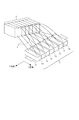
図1は、本実施形態に係るインクジェット記録装置の概念的な構成を示す斜視図である。ヘッドユニット1には、7つの記録ヘッド1a、1b、1c、1d、1e、1f、1gが配置されている。記録ヘッド1a〜1gのそれぞれには、記録素子として発熱体(不図示)を内部に備えた複数の吐出口(ノズル)が設けられている。本実施形態では、発熱体として電気熱変換体を用いている。そして、7つの記録ヘッドは、ブラック(K)、シアン(C)、マゼンタ(M)、イエロー(Y)、ライトシアン(Lc)、ライトマゼンタ(Lm)、グレイ(Gy)の7種類のインクにそれぞれ対応している。尚、7色分のインクを備えるインクタンク3がインク供給チューブ4を介して記録ヘッド1a〜1gに接続されており、記録ヘッド毎にインクタンクからインクが供給される。また、記録ヘッド1a〜1gには、フレキシブルケーブル(不図示)が接続されており、制御回路から制御信号が送られる。
(First embodiment)
FIG. 1 is a perspective view showing a conceptual configuration of the ink jet recording apparatus according to the present embodiment. In the
本実施形態において、記録媒体2は、搬送ローラや排紙ローラ等(不図示)に挟持され、搬送モータの駆動に伴って、図中矢印で示す主走査方向(以下、X方向とする)に搬送される。各記録ヘッド1a〜1gは、位置調整機構(不図示)によって主走査方向と交差する方向(以下、Y方向または所定方向とする)に移動することで、記録媒体2との相対位置を調整することができる。そして、位置を固定された記録ヘッド1a〜1gとX方向に搬送される記録媒体2との相対移動において、記録媒体2に対してインクを吐出することにより画像が記録される。尚、記録媒体2としては普通紙、高品位専用紙、OHPシート、光沢紙、光沢フィルム、ハガキ等があり、Y方向の幅が異なる複数種類の記録媒体に対して記録可能である。
In the present embodiment, the recording medium 2 is sandwiched between transport rollers, paper discharge rollers and the like (not shown), and is driven in the main scanning direction (hereinafter referred to as X direction) indicated by an arrow in the drawing as the transport motor is driven. Be transported. Each of the
(ヘッド構造)
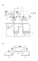
図2(a)は、本実施形態の記録ヘッド1aおよび記録ヘッド1bの詳細構造を示した図である。記録ヘッド1c〜1gの構造は記録ヘッド1aと同様である。記録ヘッド1aには、複数の記録素子が設けられた吐出基板である、記録チップ11a、12a、13a、14aが千鳥状に並べて配置されている。各記録チップには、電気熱変換体である記録素子が備えられたノズルがY方向に沿って並ぶノズル列111a、112a、113a、114aがX方向に沿って配置されている。また、各記録チップには、吐出基板表面の温度を検出するためのダイオードセンサ6が、Y方向において複数設けられている。尚、各記録チップ11a〜14aはインク供給路5によって直列につながれており、図の左から右に向かって矢印で示す順番の流路でインクが供給される。記録ヘッド1b〜1gの構造も記録ヘッド1aと同様であるが、各記録ヘッドの配置は、Y方向において記録チップのつなぎ部分が同じ位置と重ならないようにずれて配置されている。
(Head structure)
FIG. 2A is a diagram illustrating a detailed structure of the
記録媒体2を搬送する際、Y方向の位置は複数の位置を変更可能であり、記録ヘッドの温度上昇を考慮すると、記録ジョブ毎に変更することが望ましい。例えば、画像記録を指示するジョブを受信した際に、図中の記録媒体2の位置で搬送し、次に画像記録を指示するジョブを受信した際には、前回と隣の位置である記録媒体2’の位置で搬送する。これにより、記録ヘッドの記録可能な幅よりも狭い幅の記録媒体に画像を記録する場合には、複数の記録位置で記録を行うことができる。この記録位置の変更は、ジョブ毎であってもよく、所定時間毎であってもよく、所定枚数の画像毎であってもよい。また、上記例では、連続する2回のジョブにおいて前回の記録位置の隣の位置に移動したが、記録範囲の重なりがあってもよく、もっと離れた位置であってもよい。 When the recording medium 2 is conveyed, a plurality of positions in the Y direction can be changed, and it is desirable to change for each recording job in consideration of the temperature rise of the recording head. For example, when a job instructing image recording is received, it is conveyed at the position of the recording medium 2 in the figure, and when a job instructing image recording is received next, the recording medium at the position adjacent to the previous time Transport at 2 'position. As a result, when an image is recorded on a recording medium having a width smaller than the recordable width of the recording head, recording can be performed at a plurality of recording positions. The change of the recording position may be performed every job, every predetermined time, or every predetermined number of images. Further, in the above example, in two consecutive jobs, the position has moved to the position next to the previous recording position, but the recording ranges may overlap, or the positions may be further away.
図2(b)は、図2(a)で説明した各記録チップを裏側から見た図であり、記録ヘッド1aの内部のインク供給路5の構造を示している。図中、斜線で示す部分が図2(a)で示した記録チップ11a〜13aである。そして、矢印で示す順番でインクが流れ、上流の記録チップ11aから下流の記録チップ14aまでインクが供給される。そして、各記録チップに設けられた記録素子が発熱することによってインクに膜沸騰を生じさせ、その際に発生する気泡の圧力によってノズル(吐出口)からインク滴が吐出される。このインク滴の吐出タイミングと記録媒体2の搬送タイミングとを調整することで、記録媒体上に画像が形成される。
FIG. 2B is a diagram of each recording chip described in FIG. 2A viewed from the back side, and shows the structure of the
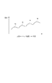
図3は、画像記録を行った際にダイオードセンサ6が検出した記録ヘッド1aの温度分布を示す図である。4aは記録チップ11aの温度分布、4bは記録チップ12aの温度分布、4cは記録チップ13aの温度分布、4dは記録チップ14aの温度分布である。画像の記録中は記録ヘッドからの熱を受けてインクの温度が上昇するため、図からわかるように、インクが流路を流れる方向において温度差が生じている。インク供給路5の上流に位置する記録チップほど温度が低く、下流に位置する記録チップほど温度が高い傾向にある。このような温度差は、インク供給路5を流れるインクが各記録チップから吐出に利用した熱エネルギーの一部を受け取り、さらにはインクが上流から下流に流れるまでに熱エネルギーが蓄積され続けるためだと考えられる。
FIG. 3 is a diagram showing the temperature distribution of the
(電気ブロック図)
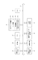
図4は、本実施形態のインクジェット記録装置における制御系の構成を示すブロック図である。51は画像データ入力部、52は操作部、53は各種処理を行うCPU部、54は各種データを記憶する記憶媒体である。記憶媒体54のプリント情報格納メモリには、記録媒体の主に種類に関する情報54a、プリントに用いるインクに関する情報54b、記録時の温度・湿度などの環境に関する情報54cが格納される。54dは、各種制御プログラム群である。55はRAM、56は画像データ処理部、57は画像出力を行う画像記録部、58は紙面予備吐出パターン生成部、59は記録に使用するノズル位置を決めるY位置決定部、60は各種データを転送するバス部である。
(Electrical block diagram)
FIG. 4 is a block diagram showing a configuration of a control system in the ink jet recording apparatus of the present embodiment. 51 is an image data input unit, 52 is an operation unit, 53 is a CPU unit that performs various processes, and 54 is a storage medium that stores various data. The print information storage memory of the
画像データ入力部51は、スキャナやデジタルカメラ等の画像入力機器からの多値画像データやパーソナルコンピュータのハードディスク等に保存されている多値画像データが入力される。操作部52は、各種パラメータの設定および記録開始を指示する各種キーを備えている。CPU53は、記憶媒体中の各種プログラムに従って本記録装置全体を記録制御手段として制御する。記憶媒体54は、制御プログラムやエラー処理プログラムに従って本記録装置を動作させるためのプログラムなどを格納している。本実施形態における動作は、全てこのプログラムに従って行われる。このようなプログラムを格納する記憶媒体54としては、ROM、FD、CD−ROM、HD、メモリカード、光磁気ディスクなどを用いることができる。RAM55は、記憶媒体54中の各種プログラムのワークエリア、エラー処理時の一時待避エリア、および画像処理時のワークエリアとして用いられる。また、RAM55は、記憶媒体54の中の各種テーブルをコピーした後、そのテーブルの内容を変更し、この変更したテーブルを参照しながら画像処理を進めることも可能である。
The image
画像データ処理部56は、入力された多値画像データをN値の画像データに画素毎に量子化するデータ生成手段として機能する。尚、Nは3以上の整数である。次いで、量子化された各画素が示す階調値“N”に基づいて、その階調値に対応するドット配置パターンを選択する。このドット配置パターンは、ドットの記録の有無、すなわちインクの吐出または非吐出を示す2値のパターンである。従って、ドット配置パターンの選択によって2値の吐出データを得ることができる。このように、画像データ処理部56は、入力された多値画像データをN値化処理した後、そのN値の画像データに基づいて2値の吐出データを作成する。例えば、8bit(256階調)で表現される多値画像データが画像データ入力部51に入力され場合、画像データ処理部56において出力する画像データの階調値を、例えば25(=24+1)値に量子化する。次いで、画像データ処理部56において、25値の画像データにドット配置パターンを割り当て、インクの吐出または非吐出を示す2値の吐出データが生成される。その後、生成された2値の吐出データを複数のノズル列に分配することにより、各ノズル列に対応する複数の2値の吐出データが生成される。尚、入力階調画像データのN値化処理を行う方法は、本実施形態で採用した多値誤差拡散法に限るものではなく、例えば、平均濃度保存法やディザマトリックス法等、任意の中間調処理方法を用いることができる。また、画像データ処理部56は、多値画像データから最終的に2値の吐出データを生成できればよく、上述したようにN値化処理を介在させることは必須ではない。例えば、画像データ処理部56に入力された多値画像データを、直接2値の吐出データに変換するような2値化処理を行ってもよい。
The image data processing unit 56 functions as data generation means for quantizing the input multi-value image data into N-value image data for each pixel. N is an integer of 3 or more. Next, based on the gradation value “N” indicated by each quantized pixel, a dot arrangement pattern corresponding to the gradation value is selected. This dot arrangement pattern is a binary pattern indicating the presence or absence of dot recording, that is, ink ejection or non-ejection. Accordingly, binary ejection data can be obtained by selecting the dot arrangement pattern. As described above, the image data processing unit 56 performs N-value processing on the input multi-value image data, and then creates binary ejection data based on the N-value image data. For example, when multi-value image data expressed in 8 bits (256 gradations) is input to the image
画像記録部57は、画像データ処理部56で生成された2値の吐出データに基づいて、対応するノズルからインク滴を吐出することにより、記録媒体上に画像を形成する。バスライン60は、本記録装置内のアドレス信号、データ、制御信号などを伝送する。
The image recording unit 57 forms an image on the recording medium by ejecting ink droplets from the corresponding nozzles based on the binary ejection data generated by the image data processing unit 56. The
Y位置決定部59は、画像を記録すべき記録媒体のサイズに基づいて記録に用いるノズルの位置を決定する。ここでは、Y方向における記録ヘッドが記録可能な幅(記録幅と呼ぶ)よりも狭い幅の記録媒体に画像を記録する場合、前回同じ幅の記録媒体に対して画像を記録した際の使用ノズル位置を取得し、Y方向においてその隣の位置を使用ノズル位置として決定する。 The Y position determination unit 59 determines the position of the nozzle used for recording based on the size of the recording medium on which the image is to be recorded. Here, when an image is recorded on a recording medium having a width narrower than the width that can be recorded by the recording head in the Y direction (referred to as a recording width), the nozzle used when the image is recorded on the recording medium having the same width last time The position is acquired, and the position adjacent to the position in the Y direction is determined as the use nozzle position.
(紙面予備吐パターン生成処理)
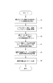
図5を用いて、紙面予備吐出パターンを決定し紙面予備吐出の吐出データを生成する紙面予備吐出データ生成処理を説明する。本実施形態では、ノズルからのインク滴の吐出状態を示す情報として、記録前のヘッド温度(ベース温度)とこれから画像を記録するためにインク滴を吐出する回数を用いる。そして、ベース温度とインク滴を吐出する回数に基づいて、記録ヘッドが到達する最高温度を推定する。推定した最高温度から、画像の記録中に画像を記録する領域に対して、記録ヘッドの吐出状態を維持するための予備吐出(紙面予備吐出)を行う間隔を決定する。
(Paper pre-discharge pattern generation processing)
The paper preliminary ejection data generation process for determining the paper preliminary ejection pattern and generating the paper preliminary ejection ejection data will be described with reference to FIG. In this embodiment, the head temperature (base temperature) before recording and the number of times ink droplets are ejected to record an image are used as information indicating the ejection state of ink droplets from the nozzles. Then, based on the base temperature and the number of times ink droplets are ejected, the maximum temperature reached by the recording head is estimated. From the estimated maximum temperature, an interval for performing preliminary discharge (paper surface preliminary discharge) for maintaining the discharge state of the recording head is determined for an area in which an image is recorded during image recording.
記録を指示するジョブを受信すると、ステップS1において、これから画像を記録する記録媒体と同じ幅の記録媒体に対して前回画像を記録した際に使用したノズルを示す情報を取得する。そして、前回使用したノズル位置とは異なる位置に、今回の画像記録に使用するノズルの位置を決定する。ここで決定されるノズル位置は、前回使用したノズルの範囲と一部のノズルが重複していても構わないが、重複していない方がより好ましい。本実施形態では、今回の記録動作では、前回の記録動作で使用したノズルを用いないように、前回使用したノズル範囲に対してY方向において隣に位置する範囲のノズルをノズル使用位置として決定する。ノズル使用位置が決定すると、決定したノズル使用位置に関する情報が記録ヘッド1の位置調整機構に送られ、位置調整機構が記録ヘッドのY位置を調整する。
When a job instructing recording is received, in step S1, information indicating the nozzle used when the previous image was recorded on the recording medium having the same width as the recording medium from which the image is to be recorded is acquired. Then, the position of the nozzle used for the current image recording is determined at a position different from the previously used nozzle position. The nozzle positions determined here may overlap with the previously used nozzle range and some of the nozzles, but it is more preferable that they do not overlap. In the present embodiment, in the current recording operation, the nozzles in the range adjacent to the previously used nozzle range in the Y direction are determined as the nozzle usage positions so that the nozzles used in the previous recording operation are not used. . When the nozzle use position is determined, information regarding the determined nozzle use position is sent to the position adjustment mechanism of the
ステップS2において、ダイオードセンサ6を用いて、画像記録を行う前の記録ヘッドの温度をノズルグループ毎に取得する。以下、この温度をベース温度と呼ぶ。ここでは、各インク色の記録ヘッドについて、Y方向において複数のノズルグループに分割する。各ノズルグループは、Y方向において連続する所定数のノズルを含む。本実施形態では、X方向において同色のインクを吐出する複数のノズル列を備える記録チップを用いているが、X方向において同じ位置を記録可能なノズルは同じノズルグループに属するように分割される。
In step S2, the temperature of the recording head before image recording is acquired for each nozzle group using the
尚、ノズルグループ毎にベース温度を取得する上で、ノズルグループ毎に少なくとも1つのダイオードセンサ6が配置されていることが好ましい。1つのノズルグループに対して複数のダイオードセンサが配置されている場合には、平均値を用いることで精度を上げることができる。また、ノズルグループ毎にダイオードセンサが配置されていない場合には、近傍の2つのダイオードセンサ6の温度と各ダイオードセンサまでの距離から補完演算することにより温度を取得してもよい。
In order to acquire the base temperature for each nozzle group, it is preferable that at least one
ステップS3では、画像データ処理部によって生成された2値の吐出データに基づいて、各ノズルグループのノズル使用回数、すなわち、これから画像を記録する上でインク滴を吐出する回数を取得する。 In step S3, based on the binary ejection data generated by the image data processing unit, the number of times the nozzles are used for each nozzle group, that is, the number of times ink droplets are ejected in order to record an image is acquired.
ステップS4において、ステップS2で取得したベース温度と、ステップS3で取得したノズル使用回数とに基づいて、各ノズルグループの最高到達温度Tを推定する。 In step S4, based on the base temperature acquired in step S2 and the number of times the nozzle is used acquired in step S3, the maximum temperature T of each nozzle group is estimated.
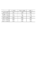
図6は、ステップS2で取得したベース温度tとステップS3で取得したインク使用回数に基づいて、ステップS4で用いる最高到達温度Tを推定するためのテーブルである。このテーブルにおいて、記録開始前のベース温度によって記録ヘッドの昇温度合いが異なるため、予めこのようなテーブルを生成し、記憶媒体54に記憶しておく。
FIG. 6 is a table for estimating the maximum temperature T used in step S4 based on the base temperature t acquired in step S2 and the ink usage count acquired in step S3. In this table, since the degree of temperature rise of the recording head varies depending on the base temperature before the start of recording, such a table is generated in advance and stored in the
ステップS5において、紙面予備吐出パターン生成部58は、S4で推定した各ノズルグループの最高到達温度に基づいて、インク色毎の紙面予備吐出を行う間隔を決定する。ここでは、インク色毎に、記録に使用するノズルグループそれぞれの最高到達温度のうち最も高い最高到達温度を取得し、この温度に対応する値を紙面予備吐出間隔として決定する。 In step S5, the paper surface preliminary discharge pattern generation unit 58 determines an interval for performing the paper surface preliminary discharge for each ink color based on the highest temperature of each nozzle group estimated in S4. Here, for each ink color, the highest maximum temperature among the maximum temperatures of the nozzle groups used for recording is acquired, and a value corresponding to this temperature is determined as the paper preliminary ejection interval.
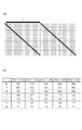
図7(a)は、紙面予備吐出データの記録媒体上の2値のイメージ図を表している。図7(a)において、各マス目は、記録媒体上の領域に1200dpi×1200dpiの解像度で設定された画素を示している。そして、黒マスはインク滴を吐出する画素、白マスはインク滴を吐出しない画素を示している。図中、Aは、紙面予備吐出としてインク滴を吐出した後、次に吐出するまでの画素数を表す吐出間隔である。 FIG. 7A shows a binary image diagram of the preliminary ejection data on the recording medium. In FIG. 7A, each square indicates a pixel set in a region on the recording medium with a resolution of 1200 dpi × 1200 dpi. Black squares indicate pixels that eject ink droplets, and white squares indicate pixels that do not eject ink droplets. In the figure, A is an ejection interval representing the number of pixels from the ejection of ink droplets as preliminary ejection on the paper surface until the next ejection.
図7(b)は、紙面予備吐出パターンを決めるためのテーブルであり、インク色と最高到達温度Tに対応して設定された吐出間隔Aの値を示している。ヘッド温度が高いほど、インク中の水分の蒸発が促進され、インクの粘度が高くなるため、最高到達温度Tが高くなるほど紙面予備吐出を短い間隔で行うように、吐出間隔Aの値が小さくなるように設定されている。 FIG. 7B is a table for determining the paper surface preliminary discharge pattern, and shows the value of the discharge interval A set corresponding to the ink color and the maximum temperature T. As the head temperature is higher, the evaporation of moisture in the ink is promoted and the viscosity of the ink is increased. Therefore, the higher the maximum temperature T, the smaller the value of the discharge interval A so that the preliminary discharge on the paper surface is performed at shorter intervals. Is set to
ステップS6において、紙面予備吐出パターン生成部58は、インク色毎に画像記録に用いるノズルグループの最高到達温度Tに基づいてテーブルから吐出間隔Aを参照し、図7(a)のパターンデータに基づいて紙面予備吐出の吐出データを生成する。尚、図7(a)のパターンデータを繰り返し用いることで、記録媒体上の全領域に対する紙面予備吐出データを生成する。 In step S6, the paper preliminary ejection pattern generation unit 58 refers to the ejection interval A from the table based on the maximum temperature T of the nozzle group used for image recording for each ink color, and based on the pattern data in FIG. Thus, ejection data for preliminary ejection on the paper surface is generated. Note that by repeatedly using the pattern data shown in FIG. 7A, the paper preliminary ejection data for the entire area on the recording medium is generated.
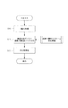
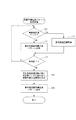
図8は、ユーザが記録を指示した記録画像の吐出データと紙面予備吐出の吐出データとを合成する処理のフローチャートである。まず、ステップS11において、0〜255の256階調で示される多値データを取得し、2値化処理が行われる。2値化手法としては、誤差拡散、INDEX展開方法など特に問わないが、ここでは前述した通り、多値データを誤差拡散法によりN値データに量子化し、そのN値データにドット配置パターンを割り当てることで2値化する処理を行う。ステップS12において、ステップS11で生成した記録画像の2値の吐出データと、図5の紙面予備吐出パターン生成フローで生成された2値の紙面予備吐出データとの論理和をとって合成する。そして、ステップS13において、合成された吐出データを各ノズル列に分配し、記録媒体上に画像を記録する。 FIG. 8 is a flowchart of a process for combining the ejection data of the recording image instructed by the user and the ejection data of the preliminary paper ejection. First, in step S11, multilevel data indicated by 256 gradations from 0 to 255 is acquired, and binarization processing is performed. The binarization method is not particularly limited, such as error diffusion or INDEX expansion method. Here, as described above, multi-value data is quantized into N-value data by the error diffusion method, and a dot arrangement pattern is assigned to the N-value data. Thus, the binarization process is performed. In step S12, the binary ejection data of the print image generated in step S11 and the binary paper surface preliminary ejection data generated in the paper preliminary ejection pattern generation flow in FIG. In step S13, the combined ejection data is distributed to each nozzle row, and an image is recorded on the recording medium.
以上のように、本実施形態では、記録すべき画像データに基づいて記録ヘッドの各位置の最高到達温度を推定し、推定した最高温度に基づいて紙面予備吐出間隔を決定する。これにより、記録すべき画像データを考慮せずに紙面予備吐出を行う場合に比べて、適切に紙面予備吐出量を調整することができ、無駄なインク消費を低減することができる。また、紙面予備吐出量を適切に調整することにより、紙面予備吐出に起因する記録画像の明度低下を抑制することも可能となる。 As described above, in this embodiment, the maximum temperature reached at each position of the recording head is estimated based on the image data to be recorded, and the paper surface preliminary ejection interval is determined based on the estimated maximum temperature. As a result, the paper surface preliminary discharge amount can be appropriately adjusted and wasteful ink consumption can be reduced as compared with the case where the paper surface preliminary discharge is performed without considering the image data to be recorded. Further, by appropriately adjusting the paper surface preliminary discharge amount, it is also possible to suppress a decrease in the brightness of the recorded image due to the paper surface preliminary discharge.
尚、本実施形態では、記録媒体を一定の記録速度で搬送する例を示しているが、記録速度が変わる形態であってもよい。記録速度が変わると紙面予備吐出を行う距離間隔が変化する。このため、紙面予備吐出を所望の時間間隔で行うために、テーブルに定められた値に、記録速度に応じた係数を乗算する方法を用いても良い。係数は記録速度が大きくなるほど大きな値になる特徴を持つ。尚、係数を持たずに、記録速度毎に紙面予備吐出パターンを決めるためのテーブルを用意する方法であっても良い。 In the present embodiment, the recording medium is conveyed at a constant recording speed. However, the recording speed may be changed. When the recording speed changes, the distance interval for performing preliminary ejection on the paper surface changes. For this reason, in order to perform the preliminary ejection on the paper surface at a desired time interval, a method of multiplying a value determined in the table by a coefficient corresponding to the recording speed may be used. The coefficient has a characteristic that the value increases as the recording speed increases. Note that a method for preparing a table for determining a paper preliminary ejection pattern for each recording speed without having a coefficient may be used.
尚、最高到達温度を決める際には、画像の記録に用いるノズル使用位置として決定された範囲のノズルを複数のグループに分け、各グループについて最高到達温度を取得する形態であってもよい。また、Y方向において複数のグループを設定しておき、ノズル使用位置として決定された範囲に含まれるグループに対し、それぞれ最高到達温度を取得する形態であってもよい。 When determining the maximum temperature, the nozzles in the range determined as the nozzle use position used for image recording may be divided into a plurality of groups, and the maximum temperature may be acquired for each group. Alternatively, a plurality of groups may be set in the Y direction, and the highest achieved temperature may be acquired for each group included in the range determined as the nozzle use position.
また、記録媒体のY方向においては同じ紙面予備吐出パターンを用いる形態を示したが、記録媒体をY方向に複数の領域に分け、各領域で紙面予備吐出パターンを決定する形態であっても良い。また、本実施形態では、テーブル参照位置の決定にあらかじめ記録されている各記録チップの最高到達温度を用いたが、各記録チップのダイオードセンサ6の値を取得し、取得した温度に基づいてテーブル参照位置を決定しても良い。
Further, although the same paper preliminary ejection pattern is used in the Y direction of the recording medium, the recording medium may be divided into a plurality of areas in the Y direction, and the paper preliminary ejection pattern may be determined in each area. . In the present embodiment, the maximum temperature reached for each recording chip recorded in advance for determining the table reference position is used. However, the value of the
また、本実施形態では、ベース温度とノズル使用回数とに基づいて最高到達温度を決定する構成としたが、ノズル使用回数からヘッド温度の上昇度合いを推定する形態であってもよい。この場合、ノズル使用回数と温度上昇分を関連づけたデータを予め記憶しておき、ノズル使用回数に基づいて温度上昇分を取得し、取得した温度上昇分をベース温度に加算して最高到達温度を推定すればよい。 Further, in this embodiment, the maximum temperature reached is determined based on the base temperature and the number of times of nozzle use. However, a form in which the degree of increase in head temperature is estimated from the number of times of nozzle use may be used. In this case, data relating the number of nozzles used and the temperature rise is stored in advance, the temperature rise is obtained based on the number of nozzles used, and the obtained temperature rise is added to the base temperature to obtain the maximum temperature reached. It may be estimated.
(第2実施形態)
前述の実施形態では、インク色毎に最高到達温度を予測して紙面予備吐出間隔を決定する方法を述べたが、本実施形態では、記録に用いるインクのうち有彩色インクの紙面予備吐出による色転びを考慮した紙面予備吐間隔を決定する方法について説明する。
(Second Embodiment)
In the above-described embodiment, the method for determining the paper preliminary discharge interval by predicting the maximum temperature reached for each ink color has been described. In this embodiment, the color of the ink used for recording by the preliminary paper discharge of chromatic ink is described. A method for determining the paper preliminary discharge interval in consideration of rollover will be described.
複数色の有彩色インクで紙面予備吐出を行う場合、紙面予備吐出されるインク量によっては、記録される画像の色の色味がずれてしまう、所謂「色転び」が生じる場合がある。この色転びの発生を抑制するために、紙面予備吐出によって作られる画像の色が無彩色になるよう、各有彩色インクの紙面予備吐出の吐出発数を調整することが好ましい。 When the paper surface preliminary ejection is performed with a plurality of chromatic color inks, a so-called “color shift” in which the color of the recorded image is shifted may occur depending on the amount of ink preliminarily ejected on the paper surface. In order to suppress the occurrence of this color shift, it is preferable to adjust the ejection number of the chromatic color ink for the preliminary ejection on the paper so that the color of the image created by the preliminary ejection on the paper becomes an achromatic color.
本実施形態では、有彩色インクとしてY、Lc、Lmインク、無彩色インクとしてGyインクの紙面予備吐出を行う場合を例に挙げて説明する。予め図7(b)のテーブルを生成する際に、有彩色インクの紙面予備吐出によって生成される画像の色が無彩色となるように、テーブルの縦に並ぶ紙面予備吐間隔の値を設定しておく。例えば、最高到達温度Tは10℃≦T<20℃の場合、Yインクの紙面予備吐間隔A=576、Lcインクの紙面予備吐間隔A=280、Lmインクの紙面予備吐間隔A=280となっている。これは、Y、Lc、Lmインクがそれぞれ上記間隔で紙面予備吐出された場合に記録された画像が無彩色であるように調整された値である。従って、第1実施形態のように、インク色毎に最高到達温度から紙面予備吐間隔Aを決定すると、有彩色インクのバランスがくずれ、記録される画像の色味が変わってしまう可能性がある。 In this embodiment, a case where Y, Lc, and Lm inks are used as chromatic inks and Gy ink is preliminarily ejected as achromatic inks will be described as an example. When the table of FIG. 7B is generated in advance, the value of the paper preliminary ejection interval arranged vertically in the table is set so that the color of the image generated by the preliminary paper ejection of chromatic ink becomes an achromatic color. Keep it. For example, when the maximum temperature T is 10 ° C. ≦ T <20 ° C., the Y ink pre-discharge interval A = 576, the Lc ink pre-discharge interval A = 280, and the Lm ink pre-discharge interval A = 280. It has become. This is a value adjusted so that the recorded image is achromatic when Y, Lc, and Lm inks are preliminarily ejected on the paper surface at the above intervals. Therefore, if the paper preliminary ejection interval A is determined from the highest temperature for each ink color as in the first embodiment, the balance of the chromatic color ink may be lost, and the color of the recorded image may change. .
そこで本実施形態では、有彩色インクの紙面予備吐出については、各インクの最高到達温度のうち最も高い最高到達温度を判定し、判定された最高到達温度に対応する紙面予備吐出間隔Aの値に決定する。すなわち、最高到達温度が最も高いインクに合わせて、他の有彩色インクの紙面予備吐間隔も決定する。 Therefore, in the present embodiment, for the preliminary discharge of chromatic ink on the paper surface, the highest highest temperature among the highest temperatures of each ink is determined, and the value of the preliminary paper discharge interval A corresponding to the determined maximum temperature is obtained. decide. That is, the paper surface preliminary ejection interval of other chromatic color inks is also determined in accordance with the ink having the highest maximum temperature.
図9は、本実施形態における紙面予備吐出パターン生成の処理を示すフローチャートである。ステップS21において、紙面予備吐出パターン生成部58は、紙面予備吐出パターンを生成する対象のインクが、無彩色インクであるか否かを判定する。無彩色インクであると判定された場合には、ステップS22に進み、無彩色インクの紙面予備吐出パターン生成処理を行う。無彩色インクの紙面予備吐パターン生成処理は、第1実施形態と同様に各インク毎に紙面予備吐間隔を決定する方法であり、図5のフローチャートと同じ処理であるためここでは省略する。ステップ21において、無彩色インクではない、すなわち有彩色インクであると判定された場合には、ステップS23に進み、判定された有彩色インクについて、最高到達温度を取得する。ステップS24において、紙面予備吐出を行う全てのインクについて判定が行われたかどうかを判断し、全てのインクについて行われていない場合にはステップS21に戻る。紙面予備吐出を行う全てのインクに判定が行われた場合には、ステップS25に進み、有彩色インクそれぞれについて取得した最高到達温度のうち最も高い最高到達温度Tを判定し、判定された最高到達温度に対応する紙面予備吐出間隔を決定する。例えば、Yインクの最高到達温度が15℃、Lcインクの最高到達温度が35℃、Lmインクの最高到達温度が25℃である場合、最も高い温度は35℃であるため、これらのインクの紙面予備吐出間隔を30℃≦T<40℃の値に合わせる。すなわち、Yインクの紙面予備吐間隔A=1152、Lcインクの紙面予備吐間隔A=560、Lmインクの紙面予備吐間隔A=560である。ステップS26において、ステップS25で決定した紙面予備吐出間隔を用いて有彩色インクの紙面予備吐出パターンを生成する。 FIG. 9 is a flowchart showing the process of generating the preliminary ejection pattern on the paper surface in the present embodiment. In step S <b> 21, the paper preliminary ejection pattern generation unit 58 determines whether the target ink for generating the paper preliminary ejection pattern is an achromatic color ink. If it is determined that the ink is achromatic ink, the process proceeds to step S22, and the paper surface preliminary ejection pattern generation processing of the achromatic ink is performed. The paper surface preliminary ejection pattern generation process for achromatic ink is a method of determining the paper preliminary ejection interval for each ink as in the first embodiment, and is omitted here because it is the same process as the flowchart of FIG. If it is determined in step 21 that the ink is not achromatic ink, that is, it is chromatic color ink, the process proceeds to step S23, and the highest temperature reached is obtained for the determined chromatic color ink. In step S24, it is determined whether or not the determination has been made for all the inks to be preliminarily ejected on the paper surface. If not, the process returns to step S21. If all the inks to be preliminarily ejected on the paper have been determined, the process proceeds to step S25, where the highest maximum temperature T among the maximum temperatures acquired for each of the chromatic color inks is determined, and the determined maximum level is reached. The paper surface preliminary discharge interval corresponding to the temperature is determined. For example, when the maximum temperature of Y ink is 15 ° C., the maximum temperature of Lc ink is 35 ° C., and the maximum temperature of Lm ink is 25 ° C., the highest temperature is 35 ° C. The preliminary discharge interval is adjusted to a value of 30 ° C. ≦ T <40 ° C. That is, the Y ink pre-discharge interval A = 1115, the Lc ink pre-discharge interval A = 560, and the Lm ink pre-discharge interval A = 560. In step S26, a paper surface preliminary discharge pattern of chromatic color ink is generated using the paper surface preliminary discharge interval determined in step S25.
以上のように、本実施形態では、有彩色の各インクの紙面予備吐出を独立に決定せずに、紙面予備吐出を行う有彩色インクヘッドの中で最も高い最高到達温度を用いて決定する。これにより、有彩色インクの紙面予備吐出に起因する色転びを抑制しつつ、適切な紙面予備吐出量を調整することができる。 As described above, in the present embodiment, the preliminary discharge on the paper surface of each chromatic color ink is not determined independently, but is determined using the highest maximum temperature among the chromatic ink heads that perform preliminary discharge on the paper surface. As a result, it is possible to adjust the appropriate paper preliminary ejection amount while suppressing color shift due to preliminary paper ejection of chromatic color ink.
1 ヘッドユニット
1a〜1g 記録ヘッド
2 記録媒体
3 インクタンク
11a〜14a 記録チップ
5 インク供給路
DESCRIPTION OF
Claims (14)
前記記録媒体上に前記画像を記録する前の前記記録ヘッドの温度を取得する第1取得手段と、
前記画像を記録するためのインクの吐出または非吐出を示す吐出データを取得する第2取得手段と、
前記第1取得手段が取得した前記温度と前記第2取得手段が取得した前記吐出データとに基づいて、前記複数の記録素子からの吐出状態を維持するための予備吐出を、前記記録媒体上の前記画像を記録する領域に対して行うための予備吐出データを生成する生成手段と、
を備えることを特徴とするデータ生成装置。 A data generation device that generates data for recording an image on a recording medium using a recording head provided with a plurality of recording elements that eject ink by heat generation,
First acquisition means for acquiring the temperature of the recording head before recording the image on the recording medium;
Second acquisition means for acquiring ejection data indicating ejection or non-ejection of ink for recording the image;
Based on the temperature acquired by the first acquisition unit and the discharge data acquired by the second acquisition unit, preliminary ejection for maintaining the ejection state from the plurality of recording elements is performed on the recording medium. Generating means for generating preliminary ejection data to be performed on an area for recording the image;
A data generation device comprising:
前記第1取得手段は、前記複数のグループのそれぞれについて前記温度を取得し、
前記第2取得手段は、前記複数のグループのそれぞれについて前記吐出データを取得し、
前記生成手段は、前記複数のグループのそれぞれについて前記最高温度を推定し、推定された前記最高温度のうち、最も高い最高温度に基づいて前記予備吐出データを生成することを特徴とする請求項2から4のいずれか1項に記載のデータ生成装置。 The plurality of recording elements are divided into a plurality of groups along a predetermined direction,
The first acquisition means acquires the temperature for each of the plurality of groups,
The second acquisition means acquires the ejection data for each of the plurality of groups,
The generation unit estimates the maximum temperature for each of the plurality of groups, and generates the preliminary discharge data based on the highest maximum temperature among the estimated maximum temperatures. 5. The data generation device according to any one of items 1 to 4.
前記生成手段は、前記複数の有彩色インクにそれぞれ対応する複数の前記最高温度のうち最も高い前記最高温度に基づいて、前記複数の有彩色インクそれぞれの前記予備吐出データを生成することを特徴とする請求項2から5に記載のデータ生成装置。 A plurality of the recording heads respectively correspond to a plurality of chromatic inks,
The generating means generates the preliminary ejection data of each of the plurality of chromatic color inks based on the highest maximum temperature among the plurality of maximum temperatures respectively corresponding to the plurality of chromatic color inks. The data generation device according to claim 2.
前記記録媒体上に前記画像を記録する前の前記記録ヘッドの温度を取得する第1取得工程と、
前記画像を記録するためのインクの吐出または非吐出を示す吐出データを取得する第2取得工程と、
前記第1取得工程において取得された前記温度と前記第2取得工程において取得された前記吐出データとに基づいて、前記複数の記録素子からの吐出状態を維持するための予備吐出を、前記記録媒体上の前記画像を記録する領域に対して行うための予備吐出データを生成する生成工程と、
を備えることを特徴とするデータ生成方法。 A data generation method for generating data for recording an image on a recording medium using a recording head provided with a plurality of recording elements that eject ink by heat generation,
A first acquisition step of acquiring a temperature of the recording head before recording the image on the recording medium;
A second acquisition step of acquiring ejection data indicating ejection or non-ejection of ink for recording the image;
Based on the temperature acquired in the first acquisition step and the discharge data acquired in the second acquisition step, preliminary discharge for maintaining the discharge state from the plurality of recording elements is performed on the recording medium. A generating step for generating preliminary ejection data to be performed on the area for recording the image;
A data generation method comprising:
前記記録媒体上に前記画像を記録する前の前記記録ヘッドの温度を取得する第1取得手段と、
前記画像を記録するためのインクの吐出または非吐出を示す吐出データを取得する第2取得手段と、
前記第1取得手段が取得した前記温度と前記第2取得手段が取得した前記吐出データとに基づいて、前記複数の記録素子からの吐出状態を維持するための予備吐出を、前記記録媒体上の前記画像を記録する領域に対して行うための予備吐出データを生成する生成手段と、
前記吐出データと前記予備吐出データとに基づいて、前記記録ヘッドを駆動することにより前記画像を記録する記録制御手段と、
を備えることを特徴とする記録装置。 A recording apparatus for recording an image on a recording medium using a recording head provided with a plurality of recording elements for discharging ink by heat generation,
First acquisition means for acquiring the temperature of the recording head before recording the image on the recording medium;
Second acquisition means for acquiring ejection data indicating ejection or non-ejection of ink for recording the image;
Based on the temperature acquired by the first acquisition unit and the discharge data acquired by the second acquisition unit, preliminary ejection for maintaining the ejection state from the plurality of recording elements is performed on the recording medium. Generating means for generating preliminary ejection data to be performed on an area for recording the image;
Recording control means for recording the image by driving the recording head based on the ejection data and the preliminary ejection data;
A recording apparatus comprising:
前記第1取得手段は、前記相対位置に対応する前記温度を取得することを特徴とする請求項12に記載の記録装置。 The relative position in the predetermined direction between the recording medium and the recording head when the image is recorded can be changed,
The recording apparatus according to claim 12, wherein the first acquisition unit acquires the temperature corresponding to the relative position.
前記記録媒体上に前記画像を記録する前の前記記録ヘッドの温度と、前記画像を記録するためのインクの吐出または非吐出を示す吐出データと、を取得する工程と、
取得した前記温度と前記吐出データとに基づいて、前記複数の記録素子からの吐出状態を維持するための予備吐出を、前記記録媒体上の前記画像を記録する領域に対して行うための予備吐出データを生成する工程と、
前記吐出データと前記予備吐出データとに基づいて、前記記録ヘッドを駆動することにより前記画像を記録する工程と、
を備えることを特徴とする記録方法。
A recording method for recording an image on a recording medium using a recording head provided with a plurality of recording elements for discharging ink by heat generation,
Acquiring the temperature of the recording head before recording the image on the recording medium, and ejection data indicating ejection or non-ejection of ink for recording the image;
Based on the acquired temperature and the discharge data, preliminary discharge for performing preliminary discharge for maintaining the discharge state from the plurality of recording elements to the area on the recording medium on which the image is recorded. Generating data; and
Recording the image by driving the recording head based on the ejection data and the preliminary ejection data;
A recording method comprising:
Priority Applications (1)
| Application Number | Priority Date | Filing Date | Title |
|---|---|---|---|
| JP2013272035A JP2015123735A (en) | 2013-12-27 | 2013-12-27 | Data generation apparatus, data generation method, recording apparatus, and recording method |
Applications Claiming Priority (1)
| Application Number | Priority Date | Filing Date | Title |
|---|---|---|---|
| JP2013272035A JP2015123735A (en) | 2013-12-27 | 2013-12-27 | Data generation apparatus, data generation method, recording apparatus, and recording method |
Publications (1)
| Publication Number | Publication Date |
|---|---|
| JP2015123735A true JP2015123735A (en) | 2015-07-06 |
Family
ID=53534796
Family Applications (1)
| Application Number | Title | Priority Date | Filing Date |
|---|---|---|---|
| JP2013272035A Pending JP2015123735A (en) | 2013-12-27 | 2013-12-27 | Data generation apparatus, data generation method, recording apparatus, and recording method |
Country Status (1)
| Country | Link |
|---|---|
| JP (1) | JP2015123735A (en) |
-
2013
- 2013-12-27 JP JP2013272035A patent/JP2015123735A/en active Pending
Similar Documents
| Publication | Publication Date | Title |
|---|---|---|
| US9016821B2 (en) | Image processing apparatus and image processing method | |
| US9138991B2 (en) | Printing apparatus and control method thereof | |
| JP5782739B2 (en) | Fluid ejecting apparatus and fluid ejecting method | |
| JP2008168628A (en) | Inkjet recording apparatus and inkjet recording method | |
| JP6351286B2 (en) | Recording control apparatus and recording control method | |
| JP6415080B2 (en) | Image processing apparatus, image processing method, recording apparatus, and program | |
| JP2004284279A (en) | Image processing device/method and image processing program | |
| JP2019081343A (en) | Image forming device, image processing device, and image processing method | |
| JP2016034754A (en) | Image processing apparatus, image processing method, and program | |
| JP6178708B2 (en) | Inkjet image forming apparatus | |
| JP2018149690A (en) | Image processing device, image processing program, and printer | |
| JP2007190862A (en) | Image recording device and image recording method | |
| US20100118079A1 (en) | Ink jet recording method and ink jet recording device | |
| JP6163959B2 (en) | Liquid ejection device | |
| JP2015123736A (en) | Data generation device, data generation method, recording device and recording method | |
| US10166763B2 (en) | Printing apparatus, printing method and storage medium | |
| JP6131216B2 (en) | Printing apparatus and printing method having a plurality of nozzle groups that eject ink of the same color | |
| US8579400B2 (en) | Information processing apparatus and information processing method | |
| JP6372410B2 (en) | Data correction method, correction function acquisition method, and inkjet printer. | |
| JP5781189B2 (en) | Recording apparatus, recording method, and control apparatus | |
| JP6128794B2 (en) | Recording apparatus and recording method | |
| US8038247B2 (en) | Recording apparatus and recording method | |
| JP2014148057A (en) | Image formation device, image formation system, and program | |
| JP4857389B2 (en) | Inkjet recording device | |
| JP6949617B2 (en) | Recording device, recording method, and program |