JP2015123729A - Tread ring stiffness measuring apparatus and tread ring uniformity measuring method - Google Patents
Tread ring stiffness measuring apparatus and tread ring uniformity measuring method Download PDFInfo
- Publication number
- JP2015123729A JP2015123729A JP2013271789A JP2013271789A JP2015123729A JP 2015123729 A JP2015123729 A JP 2015123729A JP 2013271789 A JP2013271789 A JP 2013271789A JP 2013271789 A JP2013271789 A JP 2013271789A JP 2015123729 A JP2015123729 A JP 2015123729A
- Authority
- JP
- Japan
- Prior art keywords
- tread ring
- measurement region
- tread
- measurement
- ring
- Prior art date
- Legal status (The legal status is an assumption and is not a legal conclusion. Google has not performed a legal analysis and makes no representation as to the accuracy of the status listed.)
- Granted
Links
Images


Landscapes
- Tires In General (AREA)
- Tyre Moulding (AREA)
Abstract
Description
本発明は、トレッドリングの剛性測定装置及びトレッドリングの均一性測定方法に関する。 The present invention relates to a tread ring stiffness measuring apparatus and a tread ring uniformity measuring method.
従来から、空気入りタイヤの製造ラインにおいては、転動時のタイヤの振動を抑制するため、製造されたタイヤのユニフォミティの各種特性(例えば、RFV,LFV,コニシティ等)が、出荷前に検査されている。空気入りタイヤは、測定用のリムに装着されて、ユニフォミティの諸特性が測定される。例えば、空気入りタイヤが装着されたリムを回転させることにより、ユニフォミティ測定装置のドラム等に接地している測定領域が空気入りタイヤの円周方向の異なる位置に移動され、空気入りタイヤの縦剛性の分布が得られる。 Conventionally, in the production line of pneumatic tires, various characteristics (eg, RFV, LFV, conicity, etc.) of manufactured tires are inspected before shipment in order to suppress tire vibration during rolling. ing. A pneumatic tire is mounted on a rim for measurement, and various characteristics of uniformity are measured. For example, by rotating a rim equipped with a pneumatic tire, the measurement area that is in contact with the drum or the like of the uniformity measurement device is moved to a different position in the circumferential direction of the pneumatic tire. Is obtained.
空気入りタイヤに荷重が負荷されると、接地している測定領域が大きく変形し、接地していない非測定領域の変形は小さいため、一般に空気入りタイヤの縦剛性の分布は、測定領域の縦剛性に大きく依存する。 When a load is applied to the pneumatic tire, the measurement area that is in contact with the ground is greatly deformed, and the deformation in the non-measurement area that is not in contact with the ground is small. It depends greatly on the rigidity.
一方、接地面を有する円筒状のトレッドリングと、トレッドリングの半径方向内側に配されかつ車軸に固定されるハブと、トレッドリングとハブとを連結するスポークとを備えるエアレスタイヤにおいても、空気入りタイヤと同様に、優れたユニフォミティ性能が求められる。完成したエアレスタイヤのユニフォミティは、ハブを測定装置に装着することにより、空気入りタイヤと同様に測定できる。 On the other hand, even in an airless tire comprising a cylindrical tread ring having a ground contact surface, a hub that is arranged radially inside the tread ring and fixed to an axle, and a spoke that connects the tread ring and the hub, Similar to tires, excellent uniformity performance is required. The uniformity of the completed airless tire can be measured in the same way as a pneumatic tire by attaching the hub to the measuring device.
ところで、エアレスタイヤにあっては、トレッドリングとハブとの偏心の他、トレッドリング単体の均一性、すなわちトレッドリング単体での円周方向の縦剛性の分布も、ユニフォミティに影響を及ぼすと考えられる。従って、トレッドリング単体での円周方向の縦剛性の分布が測定できれば、エアレスタイヤのユニフォミティ性能をより一層高めることができる。 By the way, in the airless tire, in addition to the eccentricity of the tread ring and the hub, the uniformity of the tread ring alone, that is, the distribution of the longitudinal rigidity in the circumferential direction of the tread ring alone, is considered to affect the uniformity. . Therefore, if the distribution of longitudinal rigidity in the circumferential direction of the tread ring alone can be measured, the uniformity performance of the airless tire can be further enhanced.
しかしながら、単体のトレッドリングで接地している測定領域の縦剛性を測定すべくトレッドリングに縦荷重を加えた場合、完成品のエアレスタイヤとは異なり、トレッドリングの全体が楕円状に変形し、その各部が相応の応力を発生する。例えば、測定領域及びその直上の領域では、トレッドリングの外周側に圧縮応力が発生し、内周側に引張応力が発生する。一方、その他の領域では、トレッドリングの外周側に引張応力が発生し、内周側に圧縮応力が発生する。このため、接地している測定領域が発生する応力に加えて、接地していない非測定領域が発生する応力までもが、縦剛性の測定値に影響を及ぼす。 However, when a vertical load is applied to the tread ring to measure the vertical rigidity of the measurement area that is grounded with a single tread ring, the entire tread ring is deformed into an oval shape, unlike the finished airless tire, Each part generates a corresponding stress. For example, in the measurement region and the region immediately above it, compressive stress is generated on the outer peripheral side of the tread ring, and tensile stress is generated on the inner peripheral side. On the other hand, in other regions, tensile stress is generated on the outer peripheral side of the tread ring, and compressive stress is generated on the inner peripheral side. For this reason, in addition to the stress that occurs in the measurement area that is in contact with the ground, the stress that occurs in the non-measurement area that is not in contact with the ground affects the measurement value of the longitudinal rigidity.
さらには、トレッドリングに縦荷重を加えながら、トレッドリングを円周方向に回転させる技術が確立されておらず、トレッドリングの全周にわたって剛性分布を効率よく測定することが困難であった。特にエアレスタイヤの生産ラインでは、トレッドリングの剛性を全数又は抜き取りで検査するために、トレッドリング全周の剛性分布を効率よく測定する技術が、強く求められている。 Furthermore, a technique for rotating the tread ring in the circumferential direction while applying a longitudinal load to the tread ring has not been established, and it has been difficult to efficiently measure the stiffness distribution over the entire circumference of the tread ring. In particular, in the production line of airless tires, a technique for efficiently measuring the rigidity distribution of the entire tread ring is strongly required in order to inspect the rigidity of the tread ring in its entirety or by sampling.
本発明は、以上のような実状に鑑み案出されたもので、エアレスタイヤのトレッドリング単体での円周方向の一部分の剛性分布を効率よく測定可能とするトレッドリングの剛性測定装置及びトレッドリングの均一性測定方法を提供することを主たる目的としている。 The present invention has been devised in view of the above circumstances, and a tread ring stiffness measuring apparatus and tread ring capable of efficiently measuring a stiffness distribution in a circumferential direction of a tread ring alone of an airless tire. The main purpose is to provide a uniformity measurement method.
本発明は、接地面を有する円筒状のトレッドリングと、前記トレッドリングの半径方向内側に配されかつ車軸に固定されるハブと、前記トレッドリングと前記ハブとを連結するスポークとを備えたエアレスタイヤに用いられる前記トレッドリング単体の円周方向の一部分の剛性を測定するためのトレッドリングの剛性測定装置であって、前記トレッドリング単体を円周方向に回転可能に保持するサポート治具を含み、前記サポート治具は、前記トレッドリングの前記一部分である測定領域を変形可能に外部に露出させる開放部と、前記トレッドリングの前記測定領域以外の領域である非測定領域と当接し、前記非測定領域を実質的に変形不能に拘束する拘束部とを有し、前記拘束部は、前記非測定領域との摩擦を低減する摩擦低減手段を有することを特徴とする。 The present invention relates to an airless comprising a cylindrical tread ring having a grounding surface, a hub that is arranged radially inside the tread ring and fixed to an axle, and a spoke that connects the tread ring and the hub. A tread ring stiffness measuring device for measuring the stiffness of a part of the tread ring used in a tire in the circumferential direction, including a support jig for rotatably holding the tread ring alone in the circumferential direction. The support jig is in contact with an open part that exposes the measurement region that is a part of the tread ring to the outside in a deformable manner, and a non-measurement region that is a region other than the measurement region of the tread ring, A restraining portion that restrains the measurement region so as to be substantially undeformable, and the restraining portion has a friction reducing means that reduces friction with the non-measurement region. It is characterized in.
本発明に係る前記トレッドリングの剛性測定装置において、前記拘束部は、前記非測定領域で前記トレッドリングの前記接地面と当接し、前記トレッドリングを拘束する外側サポート部を有し、前記摩擦低減手段は、外側サポート部に設けられていることが望ましい。 In the tread ring stiffness measuring apparatus according to the present invention, the restraining portion includes an outer support portion that abuts the grounding surface of the tread ring in the non-measurement region and restrains the tread ring, and reduces the friction. The means is preferably provided on the outer support.
本発明に係る前記トレッドリングの剛性測定装置において、前記摩擦低減手段は、回転可能に軸支され、前記トレッドリングの前記接地面と当接する外周面を有する複数の外側ローラーを含むことが望ましい。 In the tread ring stiffness measuring apparatus according to the present invention, it is preferable that the friction reducing means includes a plurality of outer rollers that are rotatably supported and have an outer peripheral surface that abuts against the ground contact surface of the tread ring.
本発明に係る前記トレッドリングの剛性測定装置において、前記拘束部は、前記非測定領域で、前記トレッドリングの半径方向の内周面と当接し、前記トレッドリングを拘束する内側サポート部を有し、前記摩擦低減手段は、内側サポート部に設けられていることが望ましい。 In the tread ring stiffness measurement device according to the present invention, the restraining portion includes an inner support portion that abuts on the inner circumferential surface of the tread ring in the non-measurement region and restrains the tread ring. The friction reducing means is preferably provided on the inner support portion.
本発明に係る前記トレッドリングの剛性測定装置において、前記摩擦低減手段は、回転可能に軸支され、前記トレッドリングの前記接地面と当接する外周面を有する複数の内側ローラーを含むことが望ましい。 In the tread ring stiffness measuring apparatus according to the present invention, it is preferable that the friction reducing means includes a plurality of inner rollers that are rotatably supported and have an outer peripheral surface that abuts against the ground contact surface of the tread ring.
本発明に係る前記トレッドリングの剛性測定装置において、前記サポート治具の前記開放部は、30〜300mmの円周方向の弦長で前記トレッドリングを開放することが望ましい。 In the tread ring stiffness measuring apparatus according to the present invention, it is preferable that the opening portion of the support jig opens the tread ring with a chord length in a circumferential direction of 30 to 300 mm.
本発明に係る前記トレッドリングの剛性測定装置において、前記複数の外側ローラーの外周面と前記接地面とが当接する外側当接部を結んだ円弧の径Jiと、前記トレッドリングの前記接地面の外径Roとの比Ji/Roは、0.995〜1.02であることが望ましい。 In the tread ring rigidity measuring apparatus according to the present invention, a diameter Ji of an arc connecting outer contact portions where the outer peripheral surfaces of the plurality of outer rollers and the ground contact surface contact, and the ground contact surface of the tread ring The ratio Ji / Ro with respect to the outer diameter Ro is preferably 0.995 to 1.02.
本発明に係る前記トレッドリングの剛性測定装置において、前記複数の内側ローラーの外周面と前記内周面とが当接する内側当接部を結んだ円弧の径Joと、前記トレッドリングの前記内周面の内径Riとの比Jo/Riは、0.99〜1.03であることが望ましい。 In the tread ring stiffness measuring apparatus according to the present invention, an arc diameter Jo connecting inner contact portions where outer peripheral surfaces of the plurality of inner rollers and the inner peripheral surface contact each other, and the inner periphery of the tread ring The ratio Jo / Ri to the inner diameter Ri of the surface is preferably 0.99 to 1.03.
本発明に係る前記トレッドリングの剛性測定装置において、前記外側ローラーは、前記トレッドリングの半径方向に移動可能であることが望ましい。 In the tread ring stiffness measuring apparatus according to the present invention, it is preferable that the outer roller is movable in a radial direction of the tread ring.
本発明に係る前記トレッドリングの剛性測定装置において、前記内側ローラーは、前記トレッドリングの半径方向に移動可能であることが望ましい。 In the rigidity measuring apparatus for the tread ring according to the present invention, it is preferable that the inner roller is movable in a radial direction of the tread ring.
さらに、本発明は、接地面を有する円筒状のトレッドリングと、前記トレッドリングの半径方向内側に配されかつ車軸に固定されるハブと、前記トレッドリングと前記ハブとを連結するスポークとを備えたエアレスタイヤに用いられる前記トレッドリング単体の円周方向の剛性の均一性を調べるためのトレッドリングの均一性測定方法であって、前記トレッドリングの円周方向の一部分である測定領域を変形可能とし、かつ、前記測定領域以外の非測定領域を拘束して保持する保持工程と、前記測定領域に荷重を与えて変形状態を測定する測定工程とを含み、前記測定工程は、前記トレッドリングを円周方向にずらしながら、前記測定領域を前記トレッドリングの円周方向の異なる位置に移動させて、変形状態を連続的に測定することを特徴とする。 Furthermore, the present invention includes a cylindrical tread ring having a ground contact surface, a hub that is arranged radially inside the tread ring and fixed to an axle, and a spoke that connects the tread ring and the hub. A method for measuring the uniformity of the rigidity of the tread ring used in an airless tire in the circumferential direction of the tread ring, wherein a measurement region that is a part of the tread ring in the circumferential direction can be deformed. And a holding step for restraining and holding a non-measurement region other than the measurement region, and a measurement step for measuring a deformation state by applying a load to the measurement region, wherein the measurement step includes the tread ring. The deformation region is continuously measured by moving the measurement region to a different position in the circumferential direction of the tread ring while shifting in the circumferential direction. To.
本発明のトレッドリングの剛性測定装置は、トレッドリング単体を円周方向に回転可能に保持するサポート治具を含む。サポート治具は、トレッドリングの円周方向の一部分である測定領域を変形可能に外部に露出させる開放部と、トレッドリングの測定領域以外の非測定領域を拘束する拘束部とを有する。開放部から露出されたトレッドリングの測定領域の接地面を、例えば、ドラム又は平板等に押圧することにより、トレッドリングの剛性が測定される。このとき、拘束部がトレッドリングの非測定領域を実質的に変形不能に拘束する。これにより、トレッドリングの非測定領域に応力が発生しなくなり、トレッドリング単体の円周方向の一部分である測定領域のみの剛性が測定可能となる。 The tread ring rigidity measuring device of the present invention includes a support jig for holding a tread ring alone so as to be rotatable in the circumferential direction. The support jig includes an open portion that exposes a measurement region that is a part of the circumferential direction of the tread ring to the outside in a deformable manner, and a restraining portion that restrains a non-measurement region other than the measurement region of the tread ring. The rigidity of the tread ring is measured by pressing the contact surface of the measurement area of the tread ring exposed from the open portion against, for example, a drum or a flat plate. At this time, the restraining portion restrains the non-measurement region of the tread ring substantially undeformable. As a result, no stress is generated in the non-measurement region of the tread ring, and the rigidity of only the measurement region that is a part of the circumferential direction of the tread ring alone can be measured.
拘束部には、トレッドリングの非測定領域との摩擦を低減するための摩擦低減手段が設けられている。これにより、拘束部がトレッドリングの非測定領域を拘束している状態で、トレッドリングを拘束部に対して円周方向にずらすことができ、ひいては、測定領域がトレッドリングの円周方向の異なる位置に移動する。従って、サポート治具からトレッドリングを取り外すことなく、トレッドリングの全周にわたって、測定領域のみの剛性が連続的に効率よく測定可能となる。 The restraint portion is provided with friction reducing means for reducing friction with the non-measurement region of the tread ring. Accordingly, the tread ring can be shifted in the circumferential direction with respect to the restraining portion in a state where the restraining portion restrains the non-measurement region of the tread ring, and thus the measurement region is different in the circumferential direction of the tread ring. Move to position. Therefore, the rigidity of only the measurement region can be continuously and efficiently measured over the entire circumference of the tread ring without removing the tread ring from the support jig.
本発明のトレッドリングの均一性測定方法は、トレッドリングを保持する保持工程と、トレッドリングの変形状態を測定する測定工程とを含む。保持工程では、トレッドリングの円周方向の一部分である測定領域を変形可能とし、かつ、測定領域以外の非測定領域を拘束する。測定工程では、測定領域に荷重が与えられ、変形状態が測定される。さらに、測定工程では、トレッドリングを円周方向にずらしながら、測定領域がトレッドリングの円周方向の異なる位置に移動する。これにより、トレッドリングの全周にわたる変形状態が連続的に測定され、トレッドリング単体での均一性が効率よく測定可能となる。 The method for measuring uniformity of a tread ring according to the present invention includes a holding step for holding the tread ring and a measuring step for measuring a deformation state of the tread ring. In the holding step, the measurement region which is a part of the tread ring in the circumferential direction can be deformed, and the non-measurement region other than the measurement region is constrained. In the measurement process, a load is applied to the measurement region, and the deformation state is measured. Furthermore, in the measurement process, the measurement region moves to a different position in the circumferential direction of the tread ring while shifting the tread ring in the circumferential direction. Thereby, the deformation state over the entire circumference of the tread ring is continuously measured, and the uniformity of the tread ring alone can be measured efficiently.
以下、本発明の実施の一形態が図面に基づき説明される。
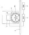
図1は、本実施形態に係るエアレスタイヤのトレッドリングの剛性測定装置(以下、単に「剛性測定装置」と言うことがある。)1の側面図である。図1に示されるように、本実施形態の剛性測定装置1は、エアレスタイヤに用いられるトレッドリング100の単体での円周方向の一部分の剛性を測定するための装置である。
Hereinafter, an embodiment of the present invention will be described with reference to the drawings.
FIG. 1 is a side view of a tread ring stiffness measuring device (hereinafter, also simply referred to as “stiffness measuring device”) 1 of an airless tire according to the present embodiment. As shown in FIG. 1, the
剛性測定装置1は、例えば、単体のトレッドリング100を保持するサポート治具2と、トレッドリング100が押圧される路面部3と、サポート治具2を路面部3の方向(縦方向)に駆動する駆動部4と、路面部3に働く縦方向の力を測定する測定部5と、測定部5によって測定された力からトレッドリング100の剛性を算出する処理部6とを備える。ここで、単体のトレッドリング100とは、エアレスタイヤとしてスポーク及びハブ等と一体化される前のトレッドリング100である。
The
本実施形態の路面部3は、水平な平板が用いられているが、この替わりに、円筒状のドラム等が用いられてもよい。 As the road surface portion 3 of this embodiment, a horizontal flat plate is used, but a cylindrical drum or the like may be used instead.
駆動部4は、サポート治具2を介してトレッドリング100を路面部3に押圧し、トレッドリング100に、例えば、エアレスタイヤの縦たわみ量に相当する変形を付与する。駆動部4によるサポート治具2の変位量は、例えば、測定部5を介して、処理部6に入力される。
The
測定部5は、駆動部4の側に設けられていてもよい。処理部6は、サポート治具2の変位及び測定部5によって測定された力に基づいて、トレッドリング100の縦剛性を算出する。
The
駆動部4によって、サポート治具2が縦方向に垂直な横方向又は前後方向に駆動されてもよい。この場合、測定部5は、路面部3に働く横方向又は前後方向の力を測定する。
The
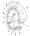
図2及び図3は、サポート治具2の構成を示している。サポート治具2は、トレッドリング100を取り外し可能に保持する。サポート治具2は、トレッドリング100の一部分である測定領域100Aを変形可能に外部に露出させる開放部21と、トレッドリング100の測定領域100A以外の領域である非測定領域100Bを実質的に変形不能に拘束する拘束部22とを有している。拘束部22がトレッドリング100の非測定領域100Bを拘束することにより、トレッドリング100の非測定領域100Bに応力が発生しなくなり、トレッドリング100単体の円周方向の一部分である測定領域100Aのみの剛性が測定可能となる。
2 and 3 show the configuration of the
拘束部22は、トレッドリング100の非測定領域100Bで接地面100Cの外側に配設される外側サポート部23と、トレッドリング100の非測定領域100Bで内周面100Dの内側に配設される内側サポート部24と、トレッドリング100の非測定領域100Bとの摩擦を低減する摩擦低減手段25、26とを有している。
The
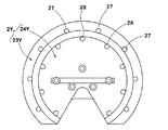
外側サポート部23は、トレッドリング100の非測定領域100Bを半径方向の外側から拘束する。外側サポート部23は、非測定領域100Bで円周方向に連続的に形成されたリング状の外輪部23Aと、外輪部23Aの一端に設けられた端縁部23Bとを有する(図3参照)。外側サポート部23の内周側には、摩擦低減手段25が設けられている。
The
外輪部23Aは、摩擦低減手段25を支持する。端縁部23Bは、外輪部23Aと一体に形成されており、外輪部23Aの変形を抑制する。端縁部23Bは、内側サポート部24と結合される。
The
端縁部23Bは、開放部21に相当する領域に、開口23Cを有する。端縁部23Bに開口23Cが設けられることにより、測定領域100Aでのトレッドリング100の端縁と外側サポート部23の端縁部23Bとの接触が回避され、測定領域100Aの変形が阻害されることがない。端縁部23Bには、内側サポート部24との結合の際、外側サポート部23と内側サポート部24との相対位置を合わせるための位置合わせ部23Dが突設されている。位置合わせ部23Dは、例えば、一対のピンからなる。
The
摩擦低減手段25は、回転可能に軸支された外側ローラー27を含んでいる。外側ローラー27は、円周方向に所定の間隔を隔てて、複数個設けられている。外側ローラー27は、トレッドリング100の接地面100Cに外接する外周面27aを有している。外側サポート部23は、トレッドリング100の非測定領域100Bの接地面100Cを、外側ローラー27を介して半径方向の外側から拘束する。
The
摩擦低減手段25には、上述した外側ローラー27に加え、例えば、いわゆる無限軌道状のベルトが設けられていてもよい。
In addition to the
図2に示されるように、内側サポート部24は、トレッドリング100の非測定領域100Bを半径方向の内側から拘束する。内側サポート部24は、円周方向に連続的に形成された円柱状の内輪部24Aを有する(図3参照)。内側サポート部24の外周側には、摩擦低減手段26が設けられている。摩擦低減手段26は、内輪部24Aによって支持される。
As shown in FIG. 2, the
摩擦低減手段26は、回転可能に軸支された内側ローラー28を含んでいる。内側ローラー28は、円周方向に所定の間隔を隔てて、複数個設けられている。内側ローラー28は、トレッドリング100の内周面100Dに内接する外周面28aを有している。内側サポート部24は、トレッドリング100の非測定領域100Bの内周面100Dを、内側ローラー28を介して半径方向の内側から拘束する。
The
摩擦低減手段26には、上述した内側ローラー28に加え、例えば、いわゆる無限軌道状のベルトが設けられていてもよい。
In addition to the
本実施形態では、拘束部22にトレッドリング100の非測定領域100Bとの摩擦を低減するための摩擦低減手段25、26が設けられているので、拘束部22がサポート治具2内で非測定領域100Bを拘束している状態で、トレッドリング100を円周方向にずらすことができる。これにより、測定領域がトレッドリング100の円周方向の異なる位置に移動する。従って、サポート治具2からトレッドリング100を取り外すことなく、トレッドリング100の全周にわたって、測定領域100Aのみの剛性が連続的に効率よく測定可能となる。
In the present embodiment, the restraining
サポート治具2は、摩擦低減手段25又は26のいずれか一方のみでトレッドリング100を拘束する構成であってもよい。しかしながら、本実施形態のように、拘束したトレッドリング100の変形を効果的に抑制すると共に、トレッドリング100の回転を円滑化するために、トレッドリング100の外周及び内周側に摩擦低減手段25及び26が設けられているのが望ましい。
The
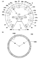
図3に示されるように、内輪部24Aは、開放部21に相当する領域に、開口24Cを有する。内輪部24Aに開口24Cが設けられることにより、測定領域100Aでのトレッドリング100の端縁と内側サポート部24の内輪部24Aとの接触が回避され、測定領域100Aの変形が阻害されることがない。内側サポート部24は、図3等に示される形態に限られず、例えば、トレッドリング100の非測定領域100Bの半径方向の内側で、摩擦低減手段26に対応する位置に、断続的に設けられる形態であってもよい。
As shown in FIG. 3, the
内側サポート部24は、外側サポート部23の端縁部23Bに、例えば、ボルト30等によって結合される。ボルト30は、内側サポート部24の内輪部24Aの端面に設けられている孔31から装着される。内側サポート部24の内輪部24Aの端面には、サポート治具2を把持するためのハンドル部32が必要に応じて設けられている。
The
図4(a)は、サポート治具2の側面を、図4(b)は、サポート治具2に装着される前のトレッドリング100の側面をそれぞれ示している。外側サポート部23と内側サポート部24とが適正な相対位置で結合されることにより、外側ローラー27と内側ローラー28とが、トレッドリング100の円周方向で同一の位置に対向して配置される。これにより、トレッドリング100が、外側ローラー27と内側ローラー28とによって挟み込まれた状態で拘束され、トレッドリング100の変形が効果的に抑制される。
4A shows a side surface of the
複数の外側ローラー27、27、27の外周面27a、27a、27aとトレッドリング100の接地面100Cとが当接する外側当接部27b、27b、27bを結んだ円弧C1の径Jiと、接地面100Cの外径Roとの比Ji/Roは、0.995〜1.02が望ましい。
A diameter Ji of an arc C1 connecting
上記比Ji/Roが0.995未満の場合、外側サポート部23の内側にトレッドリング100を装着するのが困難となる。さらには、サポート治具2内でトレッドリング100を回転させるのが困難となる。一方、上記比Ji/Roが1.02を超える場合、トレッドリング100の接地面100Cと外側ローラー27、27の外周面27aとの隙間が大きくなり、トレッドリング100の非測定領域100Bの変形を十分に抑制できないおそれがある。
When the ratio Ji / Ro is less than 0.995, it is difficult to mount the
複数の内側ローラー28、28、28の外周面28a、28a、28aとトレッドリング100の内周面100Dとが当接する内側当接部28b、28b、28bを結んだ円弧C2の径Joと、前記トレッドリングの前記内周面の内径Riとの比Jo/Riは、0.99〜1.03が望ましい。
The diameter Jo of the arc C2 connecting the
上記比Jo/Riが0.99未満の場合、トレッドリング100の内周面100Dと内側ローラー28の外周面28aとの隙間が大きくなり、トレッドリング100の非測定領域100Bの変形を十分に抑制できないおそれがある。一方、上記比Jo/Riが1.03を超える場合、内側サポート部24の外側にトレッドリング100を装着するのが困難となる。さらには、サポート治具2内でトレッドリング100を回転させるのが困難となる。
When the ratio Jo / Ri is less than 0.99, the gap between the inner
内側サポート部24は、実質的に開放部21の両外側に位置される内側ローラー28、28の内側当接部28b、28b間で、トレッドリング100の測定領域100Aを開放する。すなわち、サポート治具2の開放部21は、開放部21の両外側に位置される内側ローラー28、28の内側当接部28b、28b間の距離である円周方向の弦長CLでトレッドリング100を開放する。
The
トレッドリング100を開放する開放部21の円周方向の弦長CLは、例えば、測定対象のエアレスタイヤの接地長に応じて設定されている。一般的に、高速走行が容易で、かつ振動に敏感な乗用車では、より優れたユニフォミティ性能が、要求されている。そこで、本実施形態では、特に、乗用車用タイヤの接地長に対応するように、上記弦長CLは、例えば、30〜300mmが望ましい。弦長CLが30mm未満の場合、接地長が短くなり十分な荷重でトレッドリング100の剛性を測定することができない。一方、弦長CLが300mmを超える場合、トレッドリング100を広範囲で拘束できなくなり、非測定領域100Bの変形を十分に抑制できないおそれがある。
The chord length CL in the circumferential direction of the opening
図5には、図3等に示されるサポート治具2の変形例であるサポート治具2Xが示されている。サポート治具2Xは、外側サポート部23X及び内側サポート部24Xを有する。
FIG. 5 shows a
外側サポート部23Xは、外輪部23Aの内周部にほぼ隙間なく外側ローラー27が設けられている点で、外側サポート部23とは異なる。同様に、内側サポート部24Xは、内輪部24Aの外周部にほぼ隙間なく内側ローラー28が設けられている点で、内側サポート部24とは異なる。
The
サポート治具2Xによれば、より多くの外側ローラー27及び内側ローラー28がトレッドリング100と当接し、トレッドリング100を広範囲で拘束するため、非測定領域100Bの変形をより一層抑制できる。
According to the
図6には、図3等に示されるサポート治具2Xの別の変形例であるサポート治具2Yが示されている。サポート治具2Yは、外側サポート部23Y及び内側サポート部24Yを有する。
FIG. 6 shows a
サポート治具2Yでは、内側サポート部24Yに設けられた内側ローラー28の個数が、外側サポート部23Yに設けられた外側ローラー27の個数よりも少なく、隣り合う外側ローラー27の円周方向の間に内側ローラー28が千鳥状に配置されている点でサポート治具2とは異なる。
In the
サポート治具2Yによれば、非測定領域100Bでのトレッドリング100の変形を抑制しながら、接地面100Cと拘束部22との摩擦をより一層低減することが可能となる。サポート治具2Yにあっても、サポート治具2Xと同様に、外側ローラー27及び内側ローラー28を適宜増設可能である。
According to the
図7には、外側ローラー27及び内側ローラー28の支持構造40の一例が示されている。
FIG. 7 shows an example of a
外側ローラー27は、例えば、支持軸41、軸受け42、43、及び支持プレート44等によって、回転自在に支持されている。支持軸41は、一端が外側サポート部23の端縁部23Bに、他端が支持プレート44によって支持されている。支持軸41は、軸受け42、43を介して外側ローラー27を回転自在に支持する。
The
軸受け42、43は、外側ローラー27の両端に設けられている。本実施形態では、固定された支持軸41の周りを外側ローラー27が回転する構成であるが、軸受け42、43が端縁部23B及び支持プレート44に設けられ、支持軸41と共に外側ローラー27が回転する構成であってもよい。
The
支持プレート44は、外側サポート部23の外輪部23Aの先端縁に、例えば、ボルト45等を介して結合されている。図3等に示されるように、本実施形態では、支持プレート44は、外輪部23Aの円周方向に連続的に形成されているが、複数個によって分割されていてもよい。
The
図7に示される支持構造40によって、外側ローラー27がトレッドリング100の接地面100Cを拘束しながら円滑に回転する。これにより、非測定領域100Bでの接地面100Cと外側サポート部23との摩擦が低減される。
With the
内側ローラー28も、上述した外側ローラー27と同様であり、例えば、支持軸46、軸受け47、48、及び支持プレート49、50等によって、回転自在に支持されている。支持軸41は、一端が支持プレート49に、他端が支持プレート50によって支持されている。本実施形態では、固定された支持軸46の周りを内側ローラー28が回転する構成であるが、軸受け47、48が支持プレート49、50に設けられ、支持軸46と共に内側ローラー28が回転する構成であってもよい。
The
支持プレート49、50は、内側サポート部24の内輪部24Aの両端縁に、例えば、ボルト51、52等を介して結合されている。図3等に示されるように、支持プレート49、50は、内輪部24Aの円周方向に連続的に形成されているが、複数個によって分割されていてもよい。
The
図7に示される支持構造40によって、内側ローラー28がトレッドリング100の内周面100Dを拘束しながら円滑に回転する。これにより、非測定領域100Bでの内周面100Dと内側サポート部24との摩擦が低減される。
With the
図8には、支持構造40の変形例である支持構造40Xが示されている。支持構造40Xは、外側ローラー27及び内側ローラー28が、トレッドリング100の半径方向R1又はR2に移動可能に構成されている点で、図7に示される支持構造40とは異なる。
FIG. 8 shows a
支持構造40Xでは、外輪部23A及び端縁部23Bに対する支持軸41及び支持プレート44の相対位置をトレッドリング100の半径方向R1又はR2にずらすことにより、外側ローラー27が移動する。外側ローラー27を移動可能とするために、例えば、端縁部23Bには半径方向R1及びR2にのびる長孔61が形成されている。同様に、支持プレート44には、半径方向R1及びR2にのびる長孔62が形成されている。長孔61及び長孔62に沿って支持軸41及び支持プレート44を移動させることにより、外側ローラー27がトレッドリング100の半径方向R1又はR2に移動する。
In the
同様に、支持構造40Xでは、内輪部24Aに対する支持プレート49及び50の相対位置をトレッドリング100の半径方向R1又はR2にずらすことにより、内側ローラー28が移動する。内側ローラー28を移動可能とするために、例えば、支持プレート49には、半径方向R1及びR2にのび、ボルト51が挿通される長孔63が形成されている。同様に、支持プレート50には、半径方向R1及びR2にのび、ボルト51が挿通される長孔64が形成されている。ボルト51、52を緩めて、長孔63及び長孔64に沿って支持プレート49及び50を移動させることにより、内側ローラー28がトレッドリング100の半径方向R1又はR2に移動する。
Similarly, in the
支持構造40Xは、外側ローラー27及び内側ローラー28が、トレッドリング100の半径方向R1又はR2に移動可能に構成されているので、トレッドリング100に対する外側ローラー27及び内側ローラー28の接触圧力を微調整することができる。これにより、トレッドリング100の非測定領域100Bの変形と、外側ローラー27及び内側ローラー28とトレッドリング100との間の摩擦力とのバランスが調整可能となる。さらに、外側ローラー27及び内側ローラー28の移動範囲を適宜設定することにより、異なる径のトレッドリング100をサポート治具2に装着することが可能となり、かつトレッドリング100の非測定領域100Bが、外側ローラー27及び内側ローラー28によって、実質的に変形不能に拘束される。従って、外側サポート部23及び内側サポート部24を交換することなく、異なる径のトレッドリング100の剛性が測定可能となり、作業効率が高められる。
The
支持構造40及び支持構造40Xは、ばねなどの弾性部材を付加して、外側ローラー27をトレッドリング100の半径方向内側に、内側ローラー28をトレッドリング100の半径方向外側にそれぞれ付勢するように、構成されていてもよい。
The
図9は、剛性測定装置1を用いて、エアレスタイヤのトレッドリング100の均一性を測定する方法を示している。トレッドリング100の均一性測定方法は、トレッドリング100を保持する保持工程と、トレッドリング100の変形状態を測定する測定工程とを含んでいる。
FIG. 9 shows a method for measuring the uniformity of the
図9(a)に示されるように、保持工程では、サポート治具2を用いてトレッドリング100が保持される。すなわち、トレッドリング100は、サポート治具2の拘束部22によって、測定領域100A以外の非測定領域100Bが拘束され、保持される。このとき、サポート治具2の開放部21によって、円周方向の一部分である測定領域100Aが変形可能に開放されている。
As shown in FIG. 9A, in the holding process, the
図9(b)に示されるように、測定工程では、駆動部4によって駆動されたサポート治具2が、路面部3に向かって、すなわち、矢印A1方向に変位し、トレッドリング100の測定領域100Aに荷重が与えられる。このとき、サポート治具2の拘束部22によって、非測定領域100Bが実質的に変形不能に拘束されているので、測定領域100Aのみが変形し、応力を発生する。この測定工程では、サポート治具2の変位量と路面部3に働く力とによって、トレッドリング100の変形状態が測定される。
As shown in FIG. 9B, in the measurement process, the
その後、図9(c)に示されるように、サポート治具2がトレッドリング100の進行方向すなわち矢印D方向に変位される。これに伴い、トレッドリング100が矢印C方向に回転し、測定領域100Aがトレッドリング100の円周方向の異なる位置に移動される。このとき、トレッドリング100を支持する外側ローラー27及び内側ローラー28が、それぞれ矢印B1及びB2方向に回転し、トレッドリング100の非測定領域100Bと拘束部22との摩擦を低減する。これにより、外側サポート部23から内側サポート部24を分離等することなく、トレッドリング100を回転させることが可能となる。こうして、トレッドリング100が1周以上回転するまで、サポート治具2を矢印D方向に変位させることにより、トレッドリング100の全周にわたる変形状態が連続的に測定され、トレッドリング単体での均一性が効率よく測定可能となる。
Thereafter, as shown in FIG. 9C, the
本実施形態は、固定された路面部3に対してサポート治具2を移動させて、トレッドリング100の全周にわたる変形状態を測定する構成であるが、固定されたサポート治具2に対して路面部3を移動させるように構成されていてもよい。また、別の実施形態として、路面部3に替わりにドラムが適用される場合は、ドラムを回転させてトレッドリング100の全周にわたる変形状態が測定されてもよい。
In the present embodiment, the
以上、本発明のトレッドリングの剛性測定装置及びトレッドリングの均一性測定方法が詳細に説明されたが、本発明は上記の具体的な実施形態に限定されることなく種々の態様に変更して実施される。 The tread ring stiffness measuring apparatus and the tread ring uniformity measuring method according to the present invention have been described in detail above. However, the present invention is not limited to the specific embodiments described above, and various modifications can be made. To be implemented.
図2の基本構造をなす実施例のサポート治具を有するトレッドリングの剛性測定装置が試作され、トレッドリング単体の縦剛性が測定された。比較例1では、サポート治具を用いることなく、トレッドリング単体の縦剛性が測定された。比較例2では、摩擦低減手段を有さないサポート治具を用いて、トレッドリング単体の縦剛性が測定された。縦剛性の測定にあたっては、エアレスタイヤの諸元、例えば、外径及び幅等の寸法から同等の空気入りタイヤのロードインデックスの50%、100%、120%に相当する荷重が負荷された。 A tread ring stiffness measuring apparatus having the support jig of the embodiment having the basic structure shown in FIG. 2 was prototyped, and the longitudinal stiffness of the tread ring alone was measured. In Comparative Example 1, the longitudinal rigidity of the tread ring alone was measured without using a support jig. In Comparative Example 2, the longitudinal rigidity of the tread ring alone was measured using a support jig having no friction reducing means. In measuring the longitudinal rigidity, loads corresponding to 50%, 100%, and 120% of the load index of the equivalent pneumatic tire were applied from the specifications of the airless tire, for example, the dimensions such as the outer diameter and the width.
剛性測定可否の判定での評価“S”は、トレッドリングの回転が容易であり、かつ測定領域のみが変形し、その縦剛性が適正・連続的に測定された場合を示す。評価“A”は、トレッドリングの回転が容易であり、かつ非測定領域の一部が僅かに変形しているが、測定された縦剛性の大部分が測定領域の剛性に由来すると考えられる場合を示す。評価“B”は、トレッドリングの回転は容易であるが、トレッドリングの変形が不足し、設定された荷重で縦剛性を測定できなかった場合を示す。評価“C”は、トレッドリングの回転に若干の困難を伴ったが、測定領域の縦剛性が適正に測定された場合を示す。評価“D”は、トレッドリングが回転せず、連続的に縦剛性を測定できなかった場合を示す。評価“E”は、トレッドリングのほぼ全領域が変形し、測定された縦剛性が非測定領域の剛性の影響を相当な割合で受けていると考えられる場合を示す。
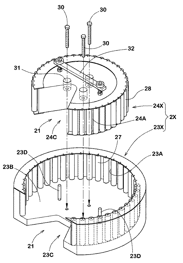
表1から明らかなように、実施例のトレッドリングの剛性測定装置は、比較例に比べて、測定領域の剛性を正確かつ連続的に効率よく測定可能であることが確認できた。 As is apparent from Table 1, it was confirmed that the tread ring stiffness measuring apparatus of the example can accurately and continuously measure the stiffness of the measurement region more efficiently than the comparative example.
1 剛性測定装置
2 サポート治具
3 平板
21 開放部
22 拘束部
23 外側サポート部
24 内側サポート部
25 摩擦低減手段
26 摩擦低減手段
27 外側ローラー
28 内側ローラー
100 トレッドリング
100A 測定領域
100B 非測定領域
100C 接地面
100D 内周面
DESCRIPTION OF
Claims (11)
前記トレッドリング単体を円周方向に回転可能に保持するサポート治具を含み、
前記サポート治具は、
前記トレッドリングの前記一部分である測定領域を変形可能に外部に露出させる開放部と、
前記トレッドリングの前記測定領域以外の領域である非測定領域と当接し、前記非測定領域を実質的に変形不能に拘束する拘束部とを有し、
前記拘束部は、前記非測定領域との摩擦を低減する摩擦低減手段を有することを特徴とするトレッドリングの剛性測定装置。 Used in an airless tire including a cylindrical tread ring having a contact surface, a hub that is arranged radially inside the tread ring and fixed to an axle, and a spoke that connects the tread ring and the hub. A tread ring stiffness measuring device for measuring the stiffness of a portion of the tread ring alone in the circumferential direction,
Including a support jig for rotatably holding the tread ring alone in the circumferential direction;
The support jig is
An opening that exposes the measurement area, which is the part of the tread ring, to the outside in a deformable manner;
A non-measurement region that is a region other than the measurement region of the tread ring, and a restraining portion that restrains the non-measurement region substantially undeformable,
The tread ring stiffness measuring device according to claim 1, wherein the restraining portion includes friction reducing means for reducing friction with the non-measurement region.
前記摩擦低減手段は、外側サポート部に設けられている請求項1記載のトレッドリングの剛性測定装置。 The restraining part has an outer support part that abuts the grounding surface of the tread ring in the non-measurement region and restrains the tread ring;
The tread ring stiffness measurement device according to claim 1, wherein the friction reducing means is provided in an outer support portion.
前記摩擦低減手段は、内側サポート部に設けられている請求項1乃至3記載のトレッドリングの剛性測定装置。 The restraining portion has an inner support portion that is in contact with a radially inner circumferential surface of the tread ring and restrains the tread ring in the non-measurement region,
4. The tread ring stiffness measuring device according to claim 1, wherein the friction reducing means is provided on an inner support portion.
前記トレッドリングの円周方向の一部分である測定領域を変形可能とし、かつ、前記測定領域以外の非測定領域を拘束して保持する保持工程と、
前記測定領域に荷重を与えて変形状態を測定する測定工程とを含み、
前記測定工程は、前記トレッドリングを円周方向にずらしながら、前記測定領域を前記トレッドリングの円周方向の異なる位置に移動させて、変形状態を連続的に測定することを特徴とするエアレスタイヤのトレッドリングの均一性測定方法。 Used in an airless tire including a cylindrical tread ring having a contact surface, a hub that is arranged radially inside the tread ring and fixed to an axle, and a spoke that connects the tread ring and the hub. A tread ring uniformity measurement method for examining the rigidity uniformity in the circumferential direction of the tread ring alone,
A holding step for deforming a measurement region that is a part of the circumferential direction of the tread ring and holding and holding a non-measurement region other than the measurement region;
Measuring the deformation state by applying a load to the measurement region,
An airless tire characterized in that in the measurement step, the deformation state is continuously measured by moving the measurement region to a different position in the circumferential direction of the tread ring while shifting the tread ring in the circumferential direction. Of measuring tread ring uniformity.
Priority Applications (6)
| Application Number | Priority Date | Filing Date | Title |
|---|---|---|---|
| JP2013271789A JP6225023B2 (en) | 2013-12-27 | 2013-12-27 | Tread ring stiffness measuring apparatus and tread ring uniformity measuring method |
| KR1020167013888A KR102244997B1 (en) | 2013-11-11 | 2014-11-11 | Device for measuring tread ring rigidity and method for measuring uniformity of tread ring |
| EP14859878.2A EP3070455B1 (en) | 2013-11-11 | 2014-11-11 | Device for measuring tread ring rigidity and method for measuring uniformity of tread ring |
| PCT/JP2014/079862 WO2015068850A1 (en) | 2013-11-11 | 2014-11-11 | Device for measuring tread ring rigidity and method for measuring uniformity of tread ring |
| CN201480058675.XA CN105814427B (en) | 2013-11-11 | 2014-11-11 | The rigid measurement device of tread rings and the uniformity method of tread rings |
| US15/030,664 US10132721B2 (en) | 2013-11-11 | 2014-11-11 | Device for measuring tread ring rigidity and method for measuring uniformity of tread ring |
Applications Claiming Priority (1)
| Application Number | Priority Date | Filing Date | Title |
|---|---|---|---|
| JP2013271789A JP6225023B2 (en) | 2013-12-27 | 2013-12-27 | Tread ring stiffness measuring apparatus and tread ring uniformity measuring method |
Publications (2)
| Publication Number | Publication Date |
|---|---|
| JP2015123729A true JP2015123729A (en) | 2015-07-06 |
| JP6225023B2 JP6225023B2 (en) | 2017-11-01 |
Family
ID=53534794
Family Applications (1)
| Application Number | Title | Priority Date | Filing Date |
|---|---|---|---|
| JP2013271789A Active JP6225023B2 (en) | 2013-11-11 | 2013-12-27 | Tread ring stiffness measuring apparatus and tread ring uniformity measuring method |
Country Status (1)
| Country | Link |
|---|---|
| JP (1) | JP6225023B2 (en) |
Cited By (1)
| Publication number | Priority date | Publication date | Assignee | Title |
|---|---|---|---|---|
| US10613001B2 (en) | 2016-11-15 | 2020-04-07 | Sumitomo Rubber Industries, Ltd. | Apparatus and method for measuring diametrical stiffness of tread ring |
Citations (7)
| Publication number | Priority date | Publication date | Assignee | Title |
|---|---|---|---|---|
| JP2614470B2 (en) * | 1987-12-15 | 1997-05-28 | 横浜ゴム株式会社 | Tire stiffness measurement method |
| JPH10123022A (en) * | 1996-10-23 | 1998-05-15 | Bridgestone Corp | Method and apparatus for testing characteristics of tread rubber |
| JP2004009768A (en) * | 2002-06-03 | 2004-01-15 | Inoac Corp | Solid tire |
| JP4530231B2 (en) * | 2007-07-31 | 2010-08-25 | 東洋ゴム工業株式会社 | Non-pneumatic tire |
| JP2011246049A (en) * | 2010-05-28 | 2011-12-08 | Toyo Tire & Rubber Co Ltd | Non-pneumatic tire |
| JP2012162259A (en) * | 2012-03-21 | 2012-08-30 | Technologie Michelin:Soc | Deflection characteristic analysis for tire state |
| US20130278044A1 (en) * | 2010-12-29 | 2013-10-24 | Michelin Recherche Et Technique S.A. | Non-pneumatic tire with reinforcement band spacer and method of manufacturing same |
-
2013
- 2013-12-27 JP JP2013271789A patent/JP6225023B2/en active Active
Patent Citations (7)
| Publication number | Priority date | Publication date | Assignee | Title |
|---|---|---|---|---|
| JP2614470B2 (en) * | 1987-12-15 | 1997-05-28 | 横浜ゴム株式会社 | Tire stiffness measurement method |
| JPH10123022A (en) * | 1996-10-23 | 1998-05-15 | Bridgestone Corp | Method and apparatus for testing characteristics of tread rubber |
| JP2004009768A (en) * | 2002-06-03 | 2004-01-15 | Inoac Corp | Solid tire |
| JP4530231B2 (en) * | 2007-07-31 | 2010-08-25 | 東洋ゴム工業株式会社 | Non-pneumatic tire |
| JP2011246049A (en) * | 2010-05-28 | 2011-12-08 | Toyo Tire & Rubber Co Ltd | Non-pneumatic tire |
| US20130278044A1 (en) * | 2010-12-29 | 2013-10-24 | Michelin Recherche Et Technique S.A. | Non-pneumatic tire with reinforcement band spacer and method of manufacturing same |
| JP2012162259A (en) * | 2012-03-21 | 2012-08-30 | Technologie Michelin:Soc | Deflection characteristic analysis for tire state |
Cited By (1)
| Publication number | Priority date | Publication date | Assignee | Title |
|---|---|---|---|---|
| US10613001B2 (en) | 2016-11-15 | 2020-04-07 | Sumitomo Rubber Industries, Ltd. | Apparatus and method for measuring diametrical stiffness of tread ring |
Also Published As
| Publication number | Publication date |
|---|---|
| JP6225023B2 (en) | 2017-11-01 |
Similar Documents
| Publication | Publication Date | Title |
|---|---|---|
| JP5778740B2 (en) | Omnidirectional moving wheel and omnidirectional moving vehicle equipped with the same | |
| KR102244997B1 (en) | Device for measuring tread ring rigidity and method for measuring uniformity of tread ring | |
| JP5525422B2 (en) | Tire vibration characteristic test apparatus and test method using the same | |
| JP6339424B2 (en) | Omnidirectional moving wheel and omnidirectional moving vehicle equipped with the same | |
| EP3842258B1 (en) | Welding shaft and wheel assembly for universal wheel and universal wheel | |
| JP2018176990A5 (en) | ||
| TWI702382B (en) | Tire testing machine | |
| TWI417530B (en) | Tire Testers and Tire Test Methods | |
| JP6225023B2 (en) | Tread ring stiffness measuring apparatus and tread ring uniformity measuring method | |
| CN104302470A (en) | Apparatus for mounting tread rings on tire base and method for manufacturing retreaded tires | |
| JP6178700B2 (en) | Tread ring stiffness measuring apparatus and tread ring uniformity measuring method | |
| US8678066B2 (en) | Apparatus and method for preparing a tire for mounting | |
| JP4665625B2 (en) | Tire testing machine | |
| CN107076642B (en) | vehicle restraint | |
| CN107413849B (en) | Horizontal cylindrical surface system for strip finishing of shaking type collecting and discharging rolling mill | |
| US9534986B2 (en) | Bicycle rim examination device | |
| US10801911B2 (en) | Wheel and tire assembly uniformity | |
| JP6424798B2 (en) | Vehicle running test equipment | |
| JP2009025236A (en) | Rim wheel for measuring uniformity and uniformity measuring method | |
| JP5275051B2 (en) | Tire uniformity machine | |
| JP2009023302A (en) | Bead-ring for vulcanization and tire vulcanizer | |
| JP2006076553A (en) | Road wheel for automobile and manufacturing method thereof | |
| JP2023030592A (en) | Apparatus for applying sound absorbing material, method for applying sound absorbing material, and method for manufacturing pneumatic tire including the same | |
| JP2009025148A (en) | Rim wheel for measuring uniformity and uniformity measuring method | |
| JP4235140B2 (en) | Core rotation balance measurement rim, balancer having the core rotation balance measurement rim, and rotation balance correction method using the balancer |
Legal Events
| Date | Code | Title | Description |
|---|---|---|---|
| A621 | Written request for application examination |
Free format text: JAPANESE INTERMEDIATE CODE: A621 Effective date: 20161018 |
|
| TRDD | Decision of grant or rejection written | ||
| A01 | Written decision to grant a patent or to grant a registration (utility model) |
Free format text: JAPANESE INTERMEDIATE CODE: A01 Effective date: 20170926 |
|
| A61 | First payment of annual fees (during grant procedure) |
Free format text: JAPANESE INTERMEDIATE CODE: A61 Effective date: 20171006 |
|
| R150 | Certificate of patent or registration of utility model |
Ref document number: 6225023 Country of ref document: JP Free format text: JAPANESE INTERMEDIATE CODE: R150 |
|
| R250 | Receipt of annual fees |
Free format text: JAPANESE INTERMEDIATE CODE: R250 |
|
| R250 | Receipt of annual fees |
Free format text: JAPANESE INTERMEDIATE CODE: R250 |
|
| R250 | Receipt of annual fees |
Free format text: JAPANESE INTERMEDIATE CODE: R250 |
|
| R250 | Receipt of annual fees |
Free format text: JAPANESE INTERMEDIATE CODE: R250 |
|
| R250 | Receipt of annual fees |
Free format text: JAPANESE INTERMEDIATE CODE: R250 |
|
| R250 | Receipt of annual fees |
Free format text: JAPANESE INTERMEDIATE CODE: R250 |