JP2015114802A - Display device and touch input method - Google Patents
Display device and touch input method Download PDFInfo
- Publication number
- JP2015114802A JP2015114802A JP2013255690A JP2013255690A JP2015114802A JP 2015114802 A JP2015114802 A JP 2015114802A JP 2013255690 A JP2013255690 A JP 2013255690A JP 2013255690 A JP2013255690 A JP 2013255690A JP 2015114802 A JP2015114802 A JP 2015114802A
- Authority
- JP
- Japan
- Prior art keywords
- touch
- display
- area
- display device
- pen
- Prior art date
- Legal status (The legal status is an assumption and is not a legal conclusion. Google has not performed a legal analysis and makes no representation as to the accuracy of the status listed.)
- Pending
Links
Images

Landscapes
- Position Input By Displaying (AREA)
Abstract
Description
本発明は、表示装置及びタッチ入力方法に関し、より詳細には、表示部に表示領域へのタッチ操作を検出するタッチセンサを有する表示装置、及びその表示装置におけるタッチ入力方法に関する。 The present invention relates to a display device and a touch input method, and more particularly to a display device having a touch sensor for detecting a touch operation on a display area in a display unit, and a touch input method in the display device.
従来から、表示部にタッチセンサが搭載されている表示装置が流通している。特許文献1,2には、静電容量方式のタッチパネルにおいて操作領域外(ベゼル部に相当)からの入力信号を検出すると、その検出された入力信号を無効にする技術が開示されている。また、特許文献3には、静電容量方式のタッチパネルにおいて操作領域外(ベゼル部に相当)からの入力信号を検出した場合に、タッチパネルにおける静電容量値のキャリブレーションを行う技術が開示されている。
Conventionally, display devices in which a touch sensor is mounted on a display unit have been distributed.
また、このような表示装置において、表示領域(表示画面)へのタッチ操作がユーザの指による入力操作であるのか或いはペンによる入力操作であるのかを判定し、その判定の結果に基づいてタッチ操作を区別して、タッチ操作がなされたことを示す情報をPC(Personal Computer)等の外部のソース機器に通知することもなされている。そのソース機器では、その情報に従い描画を行うことになる。 Further, in such a display device, it is determined whether the touch operation on the display area (display screen) is an input operation with a user's finger or an input operation with a pen, and the touch operation is performed based on the determination result. In other words, information indicating that a touch operation has been performed is notified to an external source device such as a PC (Personal Computer). The source device performs drawing according to the information.
特に、PCにおいてデザイン系のアプリケーションが起動しており、そのアプリケーションの画像を上記表示装置で表示させている場合には、そのアプリケーションにおいて、指による入力操作とペンによる入力操作とでそれぞれ別の動作をするよう割り当てられている。このように、表示装置において、通常の指による入力操作とペンによる入力操作の双方に対応させることは有用である。 In particular, when a design-type application is running on a PC and an image of the application is displayed on the display device, different operations are performed for the input operation with the finger and the input operation with the pen in the application. Assigned to do. As described above, in the display device, it is useful to deal with both the normal finger input operation and the pen input operation.
しかしながら、静電容量方式のタッチセンサを有する表示装置では、静電容量の変化量を検出しているだけであるため、指による入力操作とペンによる入力操作とを区別すること、つまりペンによる入力操作(ペン入力モード)に対応することが困難である。また、ペン入力モードに対応させるためには、一般的に表示画面にペンが接触していない浮いた状態(ホバー状態)を検出する必要があるが、静電容量方式のタッチセンサではこのホバー状態の検出も困難である。 However, since a display device having a capacitive touch sensor only detects the amount of change in capacitance, it distinguishes between a finger input operation and a pen input operation, that is, a pen input. It is difficult to cope with the operation (pen input mode). In order to support the pen input mode, it is generally necessary to detect a floating state (hover state) in which the pen is not in contact with the display screen. Is also difficult to detect.
そのため、静電容量方式のタッチセンサを有する表示装置においてペン入力モードに対応させるためには、ペン側に電力を供給して信号を発生させる機能を追加すると共に、表示装置側でその信号を検知するハードウェアを追加する、所謂、電磁誘導方式を採用する必要があった。 Therefore, in order to support the pen input mode in a display device having a capacitive touch sensor, a function for supplying power to the pen side to generate a signal is added and the signal is detected on the display device side. It was necessary to adopt a so-called electromagnetic induction method in which additional hardware was added.
また、追加のハードウェアを設けない場合には、表示装置において、OSD(On Screen Display)画像として表示させた操作メニューにより、通常の指による入力モードとペン入力モードとを切り替えるような設定を行えるようにする必要があるが、両者を切り替える度に設定を変更する必要があり、ユーザにとって面倒な操作となる。 If no additional hardware is provided, the display device can be set to switch between a normal finger input mode and a pen input mode using an operation menu displayed as an OSD (On Screen Display) image. However, it is necessary to change the setting each time the two are switched, which is a troublesome operation for the user.
なお、特許文献1〜3に記載の技術はいずれも、もしタッチパネルの操作領域(つまり表示領域)外からの検出結果が存在したとしても、その検出結果をノイズとして取り扱っている。 Note that any of the techniques described in Patent Documents 1 to 3 treats the detection result as noise even if a detection result from outside the operation area (that is, the display area) of the touch panel exists.
本発明は、上述のような実状に鑑みてなされたものであり、その目的は、静電容量方式のタッチセンサを有する表示装置において、追加のハードウェアを設けることなく且つ容易な操作で、通常のタッチ入力モードに対してペン入力モードを区別できるようにすることにある。 The present invention has been made in view of the above-described actual situation, and an object of the present invention is to provide a display device having a capacitance type touch sensor, usually without an additional hardware and with an easy operation. The pen input mode can be distinguished from the touch input mode.
上記の課題を解決するために、本発明の第1の技術手段は、画像を表示する表示部と、ユーザによる該表示部の表示領域上でのタッチ操作を検出する静電容量方式でマルチタッチ対応のタッチセンサと、前記表示部の周囲に設けられたベゼル部と、を備えた表示装置であって、前記タッチセンサが前記ベゼル部上にある所定領域内と前記表示領域内とで同時にタッチ操作を検出した場合、検出した前記表示領域内でのタッチ操作をペン入力モードで受け付ける制御部を、さらに備えたことを特徴としたものである。 In order to solve the above-mentioned problem, the first technical means of the present invention is a multi-touch by a display unit for displaying an image and a capacitive method for detecting a touch operation on a display area of the display unit by a user. A display device comprising a corresponding touch sensor and a bezel portion provided around the display portion, wherein the touch sensor touches simultaneously in a predetermined area on the bezel portion and in the display area. When an operation is detected, a control unit that receives the detected touch operation in the display area in a pen input mode is further provided.
本発明の第2の技術手段は、第1の技術手段において、前記制御部は、前記タッチセンサが前記所定領域内にある第1の所定領域内と前記表示領域内とで同時にタッチ操作を検出した場合、検出した前記表示領域内でのタッチ操作をホバー操作として受け付けることを特徴としたものである。 According to a second technical means of the present invention, in the first technical means, the control unit detects a touch operation simultaneously in the first predetermined area where the touch sensor is in the predetermined area and in the display area. In this case, the detected touch operation in the display area is received as a hover operation.
本発明の第3の技術手段は、第1又は第2の技術手段において、前記所定領域内に、前記ベゼル部と長手方向を同じくする長方形の領域である第2の所定領域を定義し、前記制御部は、前記タッチセンサが前記第2の所定領域内と前記表示領域内とで同時にタッチ操作を検出した場合、検出した前記表示領域内でのタッチ操作を、前記第2の所定領域においてタッチ操作を検出した長手方向位置に対応した筆圧レベルによる入力操作として受け付けることを特徴としたものである。 According to a third technical means of the present invention, in the first or second technical means, a second predetermined area that is a rectangular area having the same longitudinal direction as the bezel portion is defined in the predetermined area, When the touch sensor detects a touch operation in the second predetermined area and the display area at the same time, the control unit touches the detected touch operation in the display area in the second predetermined area. The operation is received as an input operation with a writing pressure level corresponding to the position in the longitudinal direction where the operation is detected.
本発明の第4の技術手段は、第1〜第3のいずれか1の技術手段において、前記制御部は、前記タッチセンサが前記所定領域内にある第3の所定領域内と前記表示領域内とで同時にタッチ操作を検出した場合、検出した前記表示領域内でのタッチ操作を、消しゴムによる消去操作として受け付けることを特徴としたものである。 According to a fourth technical means of the present invention, in any one of the first to third technical means, the control unit includes a third predetermined area and a display area in which the touch sensor is in the predetermined area. When a touch operation is detected at the same time, the detected touch operation in the display area is accepted as an erase operation using an eraser.
本発明の第5の技術手段は、第1〜第4のいずれか1の技術手段において、前記制御部は、前記タッチセンサが前記所定領域内にある第4の所定領域内と前記表示領域内とで同時にタッチ操作を検出した場合、検出した前記表示領域内でのタッチ操作を、ペンを上下反転させて使用する反転入力操作として受け付けることを特徴としたものである。 According to a fifth technical means of the present invention, in any one of the first to fourth technical means, the control unit includes a fourth predetermined area and a display area in which the touch sensor is in the predetermined area. When the touch operation is detected simultaneously, the detected touch operation in the display area is received as a reverse input operation that is used by inverting the pen up and down.
本発明の第6の技術手段は、第1〜第5のいずれか1の技術手段において、前記ベゼル部における少なくとも前記表示部に隣接する部分は、前記表示部の表面と同じ高さの表面を有することを特徴としたものである。 According to a sixth technical means of the present invention, in any one of the first to fifth technical means, at least a portion of the bezel portion adjacent to the display portion has a surface having the same height as the surface of the display portion. It is characterized by having.
本発明の第7の技術手段は、画像を表示する表示部と、ユーザによる該表示部の表示領域上でのタッチ操作を検出する静電容量方式でマルチタッチ対応のタッチセンサと、前記表示部の周囲に設けられたベゼル部と、を備えた表示装置におけるタッチ入力方法であって、前記タッチセンサが前記ベゼル部上にある所定領域内と前記表示領域内とで同時にタッチ操作を検出した場合、前記表示装置の制御部が、検出した前記表示領域内でのタッチ操作をペン入力モードで受け付けることを特徴としたものである。 A seventh technical means of the present invention includes a display unit that displays an image, a capacitive multitouch touch sensor that detects a touch operation on a display area of the display unit by a user, and the display unit A touch input method in a display device including a bezel portion provided around the touch panel, wherein the touch sensor detects a touch operation simultaneously in a predetermined area on the bezel portion and in the display area. The control unit of the display device receives a detected touch operation in the display area in a pen input mode.
本発明によれば、静電容量方式のタッチセンサを有する表示装置において、追加のハードウェアを設けることなく且つ容易な操作で、通常のタッチ入力モードに対してペン入力モードが区別できるようになる。 According to the present invention, in a display device having a capacitive touch sensor, the pen input mode can be distinguished from the normal touch input mode without providing additional hardware and with an easy operation. .
本発明に係る表示装置は、表示部、タッチセンサ、及び制御部を備える。本発明に係る表示装置としては、それに接続された外部のソース機器から有線又は無線で出力された画像を表示できるモニタ機能を有するモニタ装置が挙げられる。上記ソース機器としては、例えば設置型のPCやモバイルPCやタブレット型の端末装置(以下、タブレット端末)等の情報処理装置、携帯電話機(スマートフォンと呼ばれるものも含む)、レコーダ機器等のコンテンツ録画再生装置、BD(Blu-ray Disc;登録商標)プレーヤ等のコンテンツ再生装置などが挙げられる。 The display device according to the present invention includes a display unit, a touch sensor, and a control unit. Examples of the display device according to the present invention include a monitor device having a monitor function capable of displaying an image output from an external source device connected thereto in a wired or wireless manner. Examples of the source device include information recording devices such as stationary PCs, mobile PCs, and tablet terminal devices (hereinafter referred to as tablet terminals), mobile phones (including smartphones), recorder devices, and other content recording / playback devices. And a content playback device such as a BD (Blu-ray Disc; registered trademark) player.
以下、本発明の様々な実施形態について、表示装置としてモニタ装置を例に挙げて説明するが、本発明に係る表示装置はこれに限ったものではない。より具体的には、本発明に係る表示装置は、それ自体にコンテンツを再生するコンテンツ再生機能をもたせ、設置型PCやモバイルPCやタブレット端末等の情報処理装置、携帯電話機(スマートフォンと呼ばれるものも含む)、テレビ装置などとして構成することもできる。本発明に係る表示装置は、このようなコンテンツ再生機能を有する場合、外部のソース機器に接続するための構成を具備しないようにしてもよい。 Hereinafter, various embodiments of the present invention will be described using a monitor device as an example of a display device, but the display device according to the present invention is not limited to this. More specifically, the display device according to the present invention itself has a content playback function for playing back content, an information processing device such as a stationary PC, a mobile PC, or a tablet terminal, a mobile phone (something called a smartphone) And a television device or the like. When the display device according to the present invention has such a content reproduction function, the display device may not include a configuration for connecting to an external source device.
(第1の実施形態)
図1は、本発明の第1の実施形態に係る表示装置の一構成例を示すブロック図である。
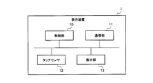
図1で例示するように、本実施形態に係る表示装置1は、その全体を制御する制御部10と、タッチセンサ12と、画像を表示する表示部13と、を備えている。また、図1で例示する表示装置1は、外部のソース機器と通信するための通信部11を備えている。
(First embodiment)
FIG. 1 is a block diagram showing a configuration example of a display device according to the first embodiment of the present invention.
As illustrated in FIG. 1, the display device 1 according to the present embodiment includes a control unit 10 that controls the entire device, a
表示部13は、画像を表示する表示パネルを有する。表示パネルとしては、液晶ディスプレイや有機エレクトロルミネッセンスディスプレイ等、様々な表示方式のパネルが挙げられる。
The
通信部11は、外部のソース機器と有線又は無線で通信するための通信インターフェイスである。この通信インターフェイスも、通信規格に応じた様々なものを適用することができる。例えば、画像を伝送するためのケーブルとしては、DP(DisplayPort;登録商標)ケーブル、High-Definition Multimedia Interface(HDMI;登録商標、以下同様)ケーブル、Mobile High-definition Link(MHL;登録商標、以下同様)規格のケーブルなど、様々なケーブルが適用できる。また、タッチ操作などのユーザ操作の情報をソース機器側に送信するためのケーブルとしては、Universal Serial Bus(USB;登録商標、以下同様)ケーブルなどの様々なケーブルが適用できる。また、無線で接続する場合には、例えば、Miracast対応のHDMIアダプタ、WiFi(登録商標)規格の無線機器などを、表示装置1やソース機器に搭載しておけばよい。
The
タッチセンサ12は、ユーザによる表示部13の表示領域(全表示領域)上でのタッチ操作を検出する静電容量方式のセンサであり、マルチタッチ対応のセンサである。タッチセンサ12は、タッチ操作を検出するとタッチ操作がなされた位置を特定する情報(入力座標情報)を制御部10に渡すか、若しくは制御部10がポーリング処理等によりタッチセンサ12に対するタッチ操作の入力を監視する。タッチセンサ12と、制御部10におけるそのタッチセンサ12を制御する部位とで、ユーザによるタッチ操作を受け付けるタッチ操作部を構成する。制御部10は、タッチ操作部によるタッチ操作入力の検出に応答して、検出された入力座標情報を取得し、その入力座標が表示部13の表示画面のどの位置であるかを判定し、その判定結果に基づいて表示部13の表示画面に表示に応じた処理等を行う。
The
また、上記した静電容量方式は、指先と導電膜の間での静電容量の変化を捉えて位置を検出する方式であり、マルチタッチに対応させるために投射型の静電容量方式を採用すればよい。静電容量方式のタッチセンサ12は、表示部(表示パネル)13の表面に重ねるようにパネルとして設けられており、タッチパネルとも言える。
In addition, the capacitance method described above is a method that detects the position by detecting the change in capacitance between the fingertip and the conductive film, and adopts a projection-type capacitance method to support multi-touch. do it. The
制御部10は、ペン入力モードで上記タッチ操作を受け付ける制御を行う。ここで、ペン入力モードは、上記タッチ操作をペンによる入力操作と見做して受け付けるモードである。これに対し、通常のモードでは、上記タッチ操作を通常のユーザの指による入力操作と見做して受け付ける。この通常のモードを「通常のタッチ入力モード」或いは単に「タッチ入力モード」と呼ぶ。 The control unit 10 performs control to accept the touch operation in the pen input mode. Here, the pen input mode is a mode in which the touch operation is accepted as an input operation with a pen. On the other hand, in the normal mode, the touch operation is accepted as an input operation with a normal user's finger. This normal mode is referred to as “normal touch input mode” or simply “touch input mode”.
このように、制御部10は、タッチ入力モードとペン入力モードとの間でモードの切り替え制御を行う。つまり、制御部10は、タッチ操作を受け付けると、その操作主体が指、ペンのいずれと見做すかを決定し、操作主体に応じた制御を行う。 Thus, the control unit 10 performs mode switching control between the touch input mode and the pen input mode. That is, when receiving a touch operation, the control unit 10 determines whether the operation subject is regarded as a finger or a pen, and performs control according to the operation subject.
また、タッチセンサ12の検出方式は静電容量方式であるため、このペン(タッチペン)は電磁誘導方式などのように電力を必要とするものではなく、単にペン先に例えば導電性のシリコンゴムなどを用いたものであればよい。
In addition, since the detection method of the
制御部10は、タッチセンサ12における上記切り替えの制御を含むタッチ入力制御のほか、表示部13における表示や通信部11における通信の制御も行う。制御部10は、プログラム保存領域に格納されたプログラムを動作させ、各種制御を行う。例えば制御部10は、CPU(Central Processing Unit)又はMPU(Micro Processing Unit)、作業領域としてのRAM(Random Access Memory)、及び記憶装置などの制御デバイスで構成され、その一部又は全部を集積回路/ICチップセットとして搭載することもできる。
The control unit 10 performs display control on the
この記憶装置には、制御プログラム(本発明に係るタッチ入力制御を実行するプログラムを含む)をはじめ、OSD(On Screen Display)画像として表示させるためのUI(User Interface)画像、各種設定内容などが記憶される。この記憶装置としては、フラッシュROM(Read Only Memory)、EEPROM(Electrically Erasable and Programmable ROM)等が挙げられる。表示装置1の種類によってはこの記憶装置としてHDD(Hard Disk Drive)を採用することもできる。 The storage device includes a control program (including a program for executing touch input control according to the present invention), a UI (User Interface) image to be displayed as an OSD (On Screen Display) image, and various setting contents. Remembered. Examples of the storage device include a flash ROM (Read Only Memory) and an EEPROM (Electrically Erasable and Programmable ROM). Depending on the type of the display device 1, an HDD (Hard Disk Drive) may be employed as the storage device.
また、表示装置1は、図示しない例えば電源キーや音量調整キーなどのハードウェアキー(操作ボタン)を有し、そのキーからの操作の入力(押下操作がなされたこと)を検出すると、その検出情報を制御部10に渡し、その押下操作に応じた処理を制御部10が実行する。例えば電源キーを所定時間(t秒とする)以上押下されることで電源のON又はOFFを実行し、t秒未満の押下により操作メニューを示すOSD画像を読み出して表示部13に重畳して表示させてもよい。このOSD画像を表示した状態で、タッチセンサ12から表示装置1についての各種設定を受け付けるようにすればよい。この設定としては、例えば入力切替、音量調節、クロック、垂直・水平方向の表示位置の変更、画質調整などが挙げられる。
Further, the display device 1 has hardware keys (operation buttons) such as a power key and a volume adjustment key (not shown), and when an operation input (pressing operation) from the keys is detected, the detection is performed. The information is passed to the control unit 10, and the control unit 10 executes processing according to the pressing operation. For example, when the power key is pressed for a predetermined time (t seconds) or longer, the power is turned on or off. When the power key is pressed for less than t seconds, an OSD image showing an operation menu is read and superimposed on the
なお、表示装置1には、タッチ操作部や操作ボタンの他に、マウス等のポインティングデバイス、ジョイスティック、タッチパッド、トラックボールなどのいずれか1又は複数を用いて操作を受け付ける操作部を設けておいてもよい。 In addition to the touch operation unit and operation buttons, the display device 1 is provided with an operation unit that receives an operation using any one or more of a pointing device such as a mouse, a joystick, a touch pad, and a trackball. May be.
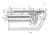
そして、図1では図示しないが、表示装置1には、表示部13の周囲にベゼル部が設けられている。このベゼル部は、基本的に表示部13を表示装置1のキャビネットに配設するための枠(外縁)であると言える。このベゼル部について、図2を参照しながら説明する。図2は、図1の表示装置におけるベゼル部近辺の一構成例を示す概略断面図である。
Although not shown in FIG. 1, the display device 1 is provided with a bezel portion around the
図2で例示する表示装置1は、液晶ユニット13aと、その表示面側に設けられたガラス等でなる前面化粧パネル14aと、前面化粧パネル14aの液晶ユニット13a側に貼り付けられたタッチパネルユニット12aと、液晶ユニット13aを前面化粧パネル14aとで覆うための背面キャビネット16aと、表示装置1の側面を覆うための側面キャビネット16bと、を備えている。図示しないが、背面キャビネット16a又は側面キャビネット16bには、操作者が押下可能な状態で上記ハードウェアキーが設けられている。
The display device 1 illustrated in FIG. 2 includes a
液晶ユニット13aは、液晶パネル13bと、その背面側に設けられた光学シート13cと、光学シート13cの背面側に設けられた導光板13dと、導光板13dの背面側に設けられた反射シート13eと、LED(Light Emitting Diode)基板13fと、を有している。LED基板13fは、導光板13dの側面から光を照射するためのLEDを有し、このLEDから照射された光は導光板13dを介して液晶パネル13bの背面から照射される。
The
また、表示装置1は、背面シャーシ15aと、パネル固定部材15bと、LED基板固定部材15cと、スペーサ15dと、スペーサ15eと、を備えている。背面シャーシ15aは、液晶ユニット13aを固定するためのシャーシであり、反射シート13eの背面側に沿って設けられ、LED基板13fの背面側に沿うように折れ曲がり、さらにタッチパネルユニット12aに沿って外側に折れ曲がった形状を有している。
The display device 1 includes a
背面シャーシ15aの端部は、スペーサ15eを挟んでタッチパネルユニット12aに押し付けられている。また、側面キャビネット16bは、背面キャビネット16aの端部に固定されると共に、前面化粧パネル14aの端部に固定されている。このような機構と、背面キャビネット16aと背面シャーシ15aとを固定する図示しない機構とにより、表示装置1の内部で背面シャーシ15aが固定されている。また、背面シャーシ15aと背面キャビネット16aとの間には、制御部10等を搭載するための図示しない基板などが設けられている。
The end of the
パネル固定部材15bは、L字状の部材であり、背面シャーシ15aにおけるLED基板13fの背面側の部分に取り付けられると共に、その部分から折れ曲がった部分により、スペーサ15dを挟んで液晶パネル13bの前面側の端部に押し付けられている。このように背面シャーシ15a及びパネル固定部材15bにより、液晶ユニット13aはスペーサ15dを介して挟持されている。
The panel fixing member 15b is an L-shaped member, and is attached to a portion of the
また、LED基板固定部材15cは、階段状の形状を有し、導光板13dの表示面側の端部を押さえると共に、LED基板13fの側面を押さえ、その反対側でパネル固定部材15bに固定されるように構成されている。このようにして、LED基板13fは、LED基板固定部材15cを介して、パネル固定部材15b及び背面シャーシ15aにより挟持されている。
Further, the LED board fixing member 15c has a stepped shape, presses the end of the
前面化粧パネル14aは、液晶ユニット13aの表示領域に対応する表示領域部分14dが透明になり、表示領域部分14dを通して液晶ユニット13aの液晶パネル13bで表示させた画像がユーザに視認できるように構成されている。また、前面化粧パネル14aは、表示領域部分14dの周囲に対応するベゼル領域部分14bが黒色等で着色されており、喩え液晶パネル13bにおいて表示領域の外側まで画像を表示させていた場合でもユーザが視認できないように構成されている。
The front
また、タッチパネルユニット12aにおけるタッチパネル12d(図1のタッチセンサ12に相当)は、液晶ユニット13aの表示を閲覧するための表示領域部分14dと同じ範囲で構成されており、その周囲にはタッチパネル12dの外枠部分12bが設けられている。
Further, the
そして、表示部13の周囲に設けられたベゼル部17は、外枠部分12bの領域を指す。また、上述のように表示部13は、前面化粧パネル14aの表示領域部分14dに対応する液晶ユニット13aの表示領域を指すことになる。
And the
ここで、図2で例示したように、表示部13の表面とベゼル部17とが段差無くフラットであることが好ましい。本発明に係る表示装置1では、その主たる特徴として後述するように、ベゼル部17上でのタッチ操作をタッチセンサ12で検知する必要があり、フラットである方が表示画面に別途部材を被せてベゼル部を形成する場合に比べて、ベゼル部17上でのタッチ(ベゼルタッチ)の位置からセンサへの距離が近く、センサの感度が良好であるためである。
Here, as illustrated in FIG. 2, it is preferable that the surface of the
また、金属は静電容量として検知されるため、表示部13の表面だけでなくベゼル部17でも金属を使用しないようにする。ベゼル部17は、例えばガラスや絶縁性樹脂を使用して形成しておけばよい。図2の例では、表示させた画像に対するタッチ操作を受け付ける操作領域(つまり表示領域)以外の領域であるベゼル部17を、前面化粧パネル14aにおいてベゼル領域部分14bだけ黒色シートを挟むか黒塗りするなどして着色して形成している。
Further, since the metal is detected as a capacitance, the metal is not used in the
また、図2では、一般的にフルフラットと呼ばれるように、ベゼル部の全てで表示画面とフラットとなった例を挙げているが、これに限らず、ベゼル部においてタッチ操作を受け付ける範囲の幅だけフラットであればよい。つまり、ベゼル部17における少なくとも表示部13に隣接する部分は、表示部13の表面と同じ高さの表面を有することが好ましい。但し、タッチセンサ12の検出感度によっては、ベゼル部は表示部13の表示領域の表面(図2の例では表示領域部分14d)に対して若干の高さをもたせてもよく、その場合、ベゼル部として、表示領域の表面と水平な面(表示領域の表面の周囲に位置する面)に有色の絶縁性樹脂を被せるなどの構造を採用すればよい。
In addition, in FIG. 2, an example in which the display screen is flat in all of the bezel part as generally called full flat is given, but the present invention is not limited thereto, and the width of a range in which a touch operation is accepted in the bezel part. It only needs to be flat. In other words, at least a portion of the
また、図2では、液晶パネル13bを有する例を挙げて説明したが、他の表示方式でも同様の考え方でベゼル部が定義できる。また、液晶パネル13bを採用する場合にも、表示装置1の断面形状は、図2で例示する構成に限ったものではなく、表示部13とベゼル部17とが区別可能であり、タッチセンサ12が表示部13の表示領域に対するタッチ操作を検出するために同じ範囲で設けられていればよい。
In FIG. 2, the example having the liquid crystal panel 13 b has been described, but the bezel portion can be defined in the same way with other display methods. Further, even when the liquid crystal panel 13b is employed, the cross-sectional shape of the display device 1 is not limited to the configuration illustrated in FIG. 2, and the
次に、本発明の主たる特徴について説明する。本発明の主たる特徴として、制御部10は、タッチセンサ12がベゼル部17上にある所定領域内と上記表示領域内(つまり上記表示領域上)とで同時にタッチ操作を検出した場合、検出した上記表示領域内でのタッチ操作を上記ペン入力モードで受け付ける。
Next, main features of the present invention will be described. As a main feature of the present invention, the control unit 10 detects the touch operation when the
なお、これらのタッチ操作は同時に検出される時間帯があればよい。つまり、まず上記所定領域内でタッチ操作がなされ、その状態のまま後から上記表示領域内でのタッチ操作を検出した場合であっても、まず上記表示領域内でのタッチ操作がなされ、その状態のまま後から上記所定領域内でタッチ操作を検出した場合であっても、制御部10は上記表示領域内でのタッチ操作をタッチ入力モードではなくペン入力モードで(つまり通常のタッチ入力ではなくペン入力として)受け付ける。 Note that these touch operations only need to have time periods that are detected simultaneously. In other words, even when a touch operation is first performed in the predetermined area and a touch operation in the display area is detected after that state, the touch operation is first performed in the display area. Even if the touch operation is detected in the predetermined area later, the control unit 10 performs the touch operation in the display area in the pen input mode (that is, not the normal touch input). Accept as pen input).
また、上記所定領域は、ベゼル部17に描画しておくか、ベゼル部17上に凹凸で表現するなどにより、物理的に線や印を入れ、ユーザが視認できるようにしておけばよい。
Further, the predetermined area may be drawn on the
ベゼル部17上にある上記所定領域内でタッチ操作を受け付けたか否かの判定は、制御部10側で行うか、若しくはタッチセンサ12自身で行うようにタッチセンサ12を構成しておけばよい。
The
まず、タッチセンサ12では、表示部13の表示領域上の各座標においてセンサをマトリクス状に配置し、各座標で静電容量を検出するように構成しておく。本発明では、上記表示領域外であるベゼル部17上の点がタッチされたことを検出する必要があるが、そのために、静電容量方式の性質を利用し、従来ノイズとして取り扱われていた検出結果を用いる。
First, the
ベゼル部17上の点であることの判定は、例えば、表示部13表示領域の端部(ベゼル部17との境界に一番近い検出座標)がタッチされたときに検出される静電容量の変化量と、ベゼル部17上でタッチ操作がなされたときに上記一番近い検出座標やそれ付近の検出座標で検出される静電容量の変化量との違いにより、判定することができる。
The determination of the point on the
前者の静電容量の変化量の方が後者の静電容量の変化量より大きいため、表示領域上のタッチを検出するための閾値(閾値Thとする)より小さなある閾値(閾値Th1とする)を設けておき、検出レベルが閾値Th以上であった場合に表示部13の表示領域上でタッチがなされたと判定し、検出レベルが閾値Thより小さく閾値Th1以上であった場合にベゼル部17上でタッチがなされたと判定すればよい。なお、閾値Th1より小さい検出結果は、表示部13でもベゼル部17上でもタッチされていない場合に発生したノイズとして取り扱う。閾値はベゼル部17の材質や高さなどによって異なるが、例えばTh=10×Th1などとして定めておけばよい。
Since the change amount of the former capacitance is larger than the change amount of the latter capacitance, a certain threshold value (referred to as threshold value Th1) that is smaller than a threshold value (referred to as threshold value Th) for detecting a touch on the display area. When the detection level is equal to or higher than the threshold Th, it is determined that a touch has been made on the display area of the
このような検出レベルの判定に加えて、或いは検出レベルの判定の代わりに、マトリクス状に配置したタッチセンサ12の各座標からの出力信号が示す波形の違いによっても、ベゼル部17上の点がタッチされたのか、或いは表示部13の表示領域の端部(ベゼル部17との境界に一番近い検出座標)がタッチされたのかを判別することができる。
In addition to the detection level determination or instead of the detection level determination, the point on the
例えば、表示部13の表示領域の非端部において、横方向に配置したセンサからの出力信号及び縦方向に配置したセンサからの出力信号は共に、実際にユーザがタッチした位置の座標において0となり、その前側の座標(又は後側の座標)で大きな山を形成し、その後側の座標(又は前側の座標)でマイナス側に大きな山を形成する、といったタッチセンサ12を用いる。
For example, both the output signal from the sensor arranged in the horizontal direction and the output signal from the sensor arranged in the vertical direction at the non-end part of the display area of the
このようなタッチセンサ12においては、表示部13の表示領域の端部(ベゼル部17との境界に一番近い検出座標)でタッチされた場合でも、タッチした位置の座標を挟んで出力信号がプラスとマイナスとなるような波形(波形aとする)となる。なお、このような波形となる理由は、タッチセンサ12で上記一番近い検出座標でのタッチ操作を検出可能とするために、上記一番近い検出座標に続くベゼル部17の範囲内の僅かな行(横長のベゼル部の場合)又は列(縦長のベゼル部の場合)の座標にもセンサを配置しているためである。
In such a
一方で、ベゼル部17上でタッチされた場合、上記一番近い検出座標付近からの出力信号は、ベゼル部17の長手方向に沿った座標軸においては上記一番近い検出座標を挟んで出力信号がプラスとマイナスになるような波形aと同様の波形を示すものの、ベゼル部17の短手方向(ベゼル部17の幅方向)に沿った座標軸においては上記一番近い検出座標でプラスかマイナスかのいずれかとなるような波形(波形aの半周期より短い波形)を示す。よって、このような波形の違いによっても、ベゼル部17上の点がタッチされたのか、或いは表示部13の表示領域の端部がタッチされたのかを判別することができる。
On the other hand, when touched on the
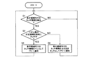
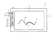
次に、タッチ入力方法について、図3及び図4を参照しながら実際の使用場面を例に挙げて説明する。図3は、図1の表示装置におけるタッチ入力方法の一例を説明するためのフロー図で、図4は、図1の表示装置におけるタッチ入力方法の一例を説明するための概略図である。 Next, the touch input method will be described with reference to FIG. 3 and FIG. 3 is a flowchart for explaining an example of the touch input method in the display device of FIG. 1, and FIG. 4 is a schematic diagram for explaining an example of the touch input method in the display device of FIG.
まず、タッチセンサ12は、表示領域上やベゼル部17上でタッチ操作がなされると、その入力座標情報と共に、そのタッチ操作がどのような動作(タッチイベント)であったかを示す情報、例えば通常のタッチ操作(タッチのみ)、スライド操作、フリック操作等、タッチ操作の種類を示す情報を検出する。タッチセンサ12は、上記入力座標情報と上記情報(以下、合わせてタッチ情報と言う)を制御部10に渡す。なお、上記情報については、上記入力座標情報から制御部10が判定するように構成することもできる。
First, when a touch operation is performed on the display area or the
制御部10は、タッチセンサ12からの検出結果に基づき、表示領域内でのタッチによるタッチ情報が検出されたか否かを判定し(ステップS1)、検出されるまで待つ。表示領域内でのタッチによるタッチ情報が検出された場合(ステップS1でYESになった場合)、制御部10は、上記所定領域内でのベゼルタッチが同時に発生したか否かを判定する(ステップS2)。
Based on the detection result from the
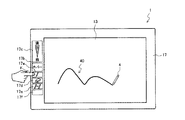
上記所定領域は、例えば図4で示す表示装置1においてベゼル部17に設けられた各領域17a〜17fを指す。特に、ペンによるタッチ操作だけを通知したい場合、つまりペン入力モードであることだけを通知したい場合には、ペン領域17aを指Fでタッチすれば、ステップS2でYESと判定されることになる。なお、他の領域17b〜17fについては、他の実施形態で後述する。
The predetermined area refers to each of the
ステップS2でYESの場合、制御部10は、検出された表示領域内でのタッチ情報をペン入力モードでの情報として、表示部13に表示されている画像を出力しているPCに通知する(ステップS3)。
In the case of YES in step S2, the control unit 10 notifies the PC that is outputting the image displayed on the
この通知を受けたPCは、ペン入力モードでタッチ操作を受けた場合の処理を実行し、処理後に出力画像を更新する。図4の例を挙げて説明する。図4では、PCにおいて例えばMicrosoft(登録商標) Windows(登録商標;以下同様。)等のOS(Operating System)上で開かれた描画アプリケーションの画像が、表示部13に表示されている例を示している。
Upon receiving this notification, the PC executes processing when a touch operation is received in the pen input mode, and updates the output image after processing. This will be described with reference to the example of FIG. FIG. 4 shows an example in which an image of a drawing application opened on an OS (Operating System) such as Microsoft (registered trademark) Windows (registered trademark; the same applies hereinafter) on the PC is displayed on the
図4で例示するように、ユーザがペン領域17aを指Fでタッチしながらペン4を用いて表示部13の表示領域内をなぞることで、上記描画アプリケーションがペンについて予め定められた所定細さの線でペン4の軌跡40を描画し、その軌跡40が表示部13に表示されることになる。
As illustrated in FIG. 4, the user traces the display area of the
なお、ここでペン4の代わりに反対の手の指など他の指を用いて表示領域内をなぞっても、PC側はペン入力モードで受け付けているため、同じ結果となり、上記所定細さの線で同じ軌跡40が描画されることになる。このように表示領域内でのタッチを実際に指で行うかペン4で行うかは問わず、この点は、他の実施形態でも同様である。
It should be noted that the same result is obtained even if the other side such as the finger of the opposite hand is used instead of the
一方、ステップS2でNOの場合、制御部10は、検出された表示領域内でのタッチ情報を通常のタッチ入力モードでの情報として、表示部13に表示されている画像を出力しているPCに通知する(ステップS4)。この通知を受けたPCは、タッチ入力モードでタッチ操作を受けた場合の処理を実行し、処理後に出力画像を更新する。
On the other hand, in the case of NO in step S2, the control unit 10 outputs the image displayed on the
図4の例を援用して説明すると、ベゼルタッチ無しで単にペン4や指Fで表示領域内をなぞった場合、上記描画アプリケーションにより図4の軌跡40と異なり線の太さが一定ではない状態で描画がなされることになる。
Referring to the example of FIG. 4, when the display area is simply traced with the
また、ペン領域17a等の上記所定領域へのベゼルタッチを検出中に限り、表示領域内でのタッチ操作を検出した場合にペン入力モードであると判定した例を示した。この場合には、ユーザが指Fを上記所定領域から離してベゼルタッチが検出されなくなったときにペン入力モードを解除することになる。
Further, an example is shown in which the pen input mode is determined when a touch operation in the display area is detected only when a bezel touch to the predetermined area such as the
代替処理として、ユーザが指Fを上記所定領域から離してベゼルタッチが検出されなくなった後でも、ペン4により描画が開始されていた場合には、ペン4が表示領域から離れて書き終わるまでペン入力モードであると判定するように(つまりペン入力モードを延長するように)制御することもできる。このような代替処理は、後述する他の実施形態でも同様に適用できる。
As an alternative process, if drawing is started with the
なお、表示装置1にPC以外のソース機器が接続されている場合にも、そのソース機器がタッチ情報を受信できる機器であれば基本的に同様である。また、表示装置1内のコンテンツ再生部で再生された画像を表示している場合にも、同様の考え方が適用でき、そのコンテンツ再生部が通常のタッチ/ペンに応じた処理を実行すればよい。 Even when a source device other than a PC is connected to the display device 1, the same is basically applied as long as the source device can receive touch information. In addition, when the image reproduced by the content reproduction unit in the display device 1 is displayed, the same concept can be applied, and the content reproduction unit only needs to execute processing according to a normal touch / pen. .
以上のように、本実施形態に係る表示装置1では、ベゼル部17へのタッチと表示画面へのタッチとを組み合わせた操作でペン入力モードを判定しているため、追加のハードウェアを設けることなく且つ容易な操作で、通常のモード(タッチ入力モード)に対してペン入力モードが区別できるようになる。
As described above, in the display device 1 according to the present embodiment, the pen input mode is determined by an operation in which the touch on the
なお、図4や後述の図5及び図6では、描画アプリケーションの画像が表示部13に表示されている例を挙げている。しかしながら、ソースから出力される画像はこれに限ったものではなく、例えばOSの基本画面の画像のようにアイコンが並んでいるような画像であってもよい。その場合でも、アイコンを選択する際に、ベゼルタッチをしながらアイコンをタッチ選択するのか、ベゼルタッチ無しでアイコンをタッチ選択するのかによって、ソース側の処理を異ならせることができる。
In FIG. 4 and FIGS. 5 and 6 to be described later, an example in which an image of a drawing application is displayed on the
(第2の実施形態)
本発明の第2の実施形態について説明する。本実施形態について、第1の実施形態との相違点を中心に説明するが、第1の実施形態で説明した様々な応用例も同様に適用できる。
(Second Embodiment)
A second embodiment of the present invention will be described. Although the present embodiment will be described with a focus on differences from the first embodiment, various application examples described in the first embodiment can be similarly applied.
本実施形態における制御部10は、タッチセンサ12が上記所定領域内にある第1の所定領域内と上記表示領域内とで同時にタッチ操作を検出した場合、検出した上記表示領域内でのタッチ操作をホバー操作として受け付ける。上記第1の所定領域の例として、図4ではホバー領域17bを挙げている。
When the
ここで、ホバー操作とは、ポインティングデバイスによりカーソルを特定要素に合わせる操作に対応する操作を指し、タッチパネルにおいてはタッチ操作に至る手前の状態(操作主体を浮かせたホバー状態)にする操作を指す。ホバー状態とは、操作主体が表示画面と所定の距離以下にあり且つ操作主体と表示画面とが接触していない状態、つまり操作主体を近接させた状態を指す。 Here, the hover operation refers to an operation corresponding to an operation for aligning the cursor with a specific element using a pointing device, and an operation to bring the touch operation into a state before the touch operation (a hover state with the operation subject floating) on the touch panel. The hover state refers to a state where the operating subject is not more than a predetermined distance from the display screen and the operating subject is not in contact with the display screen, that is, a state where the operating subject is brought close.
PCのOSやアプリケーションによっては、ホバー状態の場合に、ポインタを表示させたり、ホバーの座標を中心とし所定距離の半径をもつ円内に含まれるオブジェクトを拡大して選択可能な状態で表示させたり、或いはその円内に含まれるオブジェクトの詳細な情報を表示させたりすることが可能になっている。 Depending on the PC OS or application, in the hover state, a pointer may be displayed, or an object included in a circle having a radius of a predetermined distance centered on the hover coordinates may be displayed in a selectable state. Alternatively, it is possible to display detailed information of objects included in the circle.
制御部10は、このようにホバー操作を受け付けた場合、ソース機器やコンテンツ再生部にホバー操作であることを示す情報を通知することになる。例えば、この通知を行う通知イベントを、タッチイベントからペンイベント(ペンデジタイザイベント)を示すように切り替える。なお、上記タッチイベントとは、通常の指によるタッチを示すイベントであり、タッチ入力モードでのイベントを指す。 When the control unit 10 receives the hover operation in this way, the control unit 10 notifies the source device and the content reproduction unit of information indicating the hover operation. For example, the notification event for performing this notification is switched from a touch event to a pen event (pen digitizer event). The touch event is an event indicating a normal finger touch and refers to an event in the touch input mode.
具体的には、通知イベントのID及びフォーマットを切り替えて通知を行う。フォーマットについては、タッチイベント、ペンイベントでほぼ共通であり、例えばID,In−range,タッチされたXY座標などの情報が含まれている。なお、ユーザが指Fを上記所定領域から離してベゼルタッチが検出されなくなった後でも書き終わるまでペン入力を延長するように制御する場合には、ペン入力開始後のタッチ情報も、ペンイベントを示すIDとフォーマットでPC側に通知すればよい。 Specifically, notification is performed by switching the ID and format of the notification event. The format is almost common to touch events and pen events, and includes information such as ID, In-range, and touched XY coordinates. In addition, when the user controls the pen input to be extended until the writing is completed even after the finger F is released from the predetermined area and the bezel touch is not detected, the touch information after the start of the pen input is also changed to the pen event. What is necessary is just to notify to the PC side by ID and format to show.
上述のIn−rangeは、ホバー状態でアクティブにする記述子である。よって、通常、上記タッチイベント、上記ペンイベントのいずれの場合でも実際にタッチされた場合には、タッチを示すイベントだけでなくIn−rangeもアクティブになる。ここで、タッチを示すイベントとは、例えばtouchstart、touchmove、touchend等があり、OSによっても異なる場合もある。一方で、本実施形態では、ペンイベントであってもホバー操作であると判定された場合には、実際にタッチされているが、In−rangeのみをアクティブにして、タッチを示すイベントは非アクティブにしておけばよい。 The above-described In-range is a descriptor that is activated in a hover state. Therefore, normally, in the case of either the touch event or the pen event, when an actual touch is made, not only an event indicating a touch but also In-range is activated. Here, the event indicating touch includes, for example, touchstart, touchmove, touchend, and the like, and may differ depending on the OS. On the other hand, in this embodiment, when it is determined that the operation is a hover operation even if it is a pen event, it is actually touched, but only the in-range is activated and the event indicating the touch is inactive. Just keep it.
このように、本実施形態では、表示画面である表示領域内では実際にタッチ操作を受け付け、且つ同時に上記第1の所定領域内でのベゼルタッチを検出した場合には、実際に表示画面へのタッチがなされているにも拘わらず、上述のように表示領域内でのタッチ操作をホバー操作として受け付ける。 As described above, in the present embodiment, when a touch operation is actually received in the display area which is a display screen, and at the same time a bezel touch in the first predetermined area is detected, the display screen is actually displayed. In spite of the touch being made, the touch operation in the display area is accepted as the hover operation as described above.
これにより、ホバー操作として受け付けた旨の通知を受けたPCでは、OSやアプリケーションでホバー操作に対して規定された処理に従い、ポインタを表示させたり、ホバーの座標を中心とし所定距離の半径をもつ円内に含まれるオブジェクトを拡大して選択可能な状態で表示させたり、或いはその円内に含まれるオブジェクトの詳細な情報を表示させたりすることができる。 As a result, the PC that has received the notification that it has been accepted as a hover operation displays a pointer or has a radius of a predetermined distance centered on the hover coordinates in accordance with the processing specified for the hover operation by the OS or application. An object included in the circle can be enlarged and displayed in a selectable state, or detailed information of the object included in the circle can be displayed.
また、ホバー領域17bとペン領域17aとを双方設けておくことで、次のような一連の操作も可能となる。例えば、ユーザがホバー領域17bからペン領域17aに指Fをずらすことで、表示部13にホバー状態としてポインタを表示した状態から、線の描画を開始した状態に遷移させることもできる。或いは逆に、ユーザがペン領域17aからホバー領域17bに指Fをずらすことで、表示部13に線の描画している状態からホバー状態としてポインタを表示した状態に遷移させることもできる。
Also, by providing both the hover
また、ホバー領域17bにホバー距離を調整するためのスライダを設けておいてもよい。このスライダを設けるためには、ホバー領域17bを、ベゼル部17と長手方向を同じくする長方形の領域と定義しておけばよい。そして、このスライダは、図4で示す筆圧調整領域17cと同様にベゼル部17上に描いておけばよい。
Further, a slider for adjusting the hover distance may be provided in the hover
この場合、制御部10は、タッチセンサが上記長方形の領域内と上記表示領域内とで同時にタッチ操作を検出した場合、検出した上記表示領域内でのタッチ操作を、上記長方形の領域においてタッチ操作を検出した長手方向位置に対応したホバー距離によるホバー操作として受け付ければよい。上記ホバー距離とは、表示画面と操作主体との距離(表示画面に垂直な方向の距離)を指す。 In this case, when the touch sensor detects the touch operation in the rectangular area and the display area at the same time, the control unit 10 performs the touch operation in the detected display area in the rectangular area. May be accepted as a hover operation based on a hover distance corresponding to the position in the longitudinal direction in which is detected. The hover distance refers to the distance between the display screen and the operating subject (distance in the direction perpendicular to the display screen).
この場合、制御部10は、ホバー距離と共にホバー操作である旨も通知することになる。これにより、ユーザが指Fでベゼルタッチした上記スライダ上の位置に応じてホバー距離を変えることができる。これにより、例えば上記所定距離の半径の長短を調整することもできる。実際、上記所定距離の半径の円として、表示画面からのホバー距離に比例する半径の円を規定したアプリケーションもあり、そのようなアプリケーションに対しては、このようなスライダでホバー距離を示す情報を送信することは有益である。 In this case, the control unit 10 also notifies that the hover operation is performed together with the hover distance. Accordingly, the hover distance can be changed according to the position on the slider where the user bezel-touches with the finger F. Thereby, for example, the length of the radius of the predetermined distance can be adjusted. In fact, there is an application that defines a circle with a radius proportional to the hover distance from the display screen as a circle with a radius of the predetermined distance. For such an application, information indicating the hover distance with such a slider is provided. It is beneficial to send.
他の例として、ユーザが上記長方形の領域における「長い距離(高い位置)」から「短い距離(低い位置)」へとさらにペン領域17aへと指Fをずらす場合を想定する。この場合、操作主体を徐々に近づけていき表示画面をタッチするといった操作に対応する一連の処理が、電磁誘導方式のタッチペンを使用したタッチセンサを採用した場合と同様に、電磁誘導方式のタッチペンを使用せずに静電容量方式で実行できるようになる。或いは逆に、ユーザがペン領域17aから「短い距離」へとさらに「長い距離」へと指Fをずらすことで、表示画面をタッチした状態から操作主体を徐々に離していくといった操作に対応する一連の処理が、静電容量方式で実行できるようになる。
As another example, it is assumed that the user moves the finger F from the “long distance (high position)” to the “short distance (low position)” in the rectangular area and further to the
以上のように、本実施形態に係る表示装置1では、第1の実施形態の効果に加え、ホバー操作も容易に行うことが可能になる。 As described above, in the display device 1 according to the present embodiment, in addition to the effects of the first embodiment, a hover operation can be easily performed.
(第3の実施形態)
本発明の第3の実施形態について、図5を併せて参照しながら説明する。図5は、図1の表示装置におけるタッチ入力方法の他の例を説明するための概略図である。本実施形態について、第1,第2の実施形態との相違点を中心に説明するが、第1,第2の実施形態で説明した様々な応用例も同様に適用できる。
(Third embodiment)
A third embodiment of the present invention will be described with reference to FIG. FIG. 5 is a schematic diagram for explaining another example of the touch input method in the display device of FIG. Although the present embodiment will be described with a focus on differences from the first and second embodiments, various application examples described in the first and second embodiments can be similarly applied.
本実施形態では、上記所定領域内に、ベゼル部17と長手方向を同じくする長方形の領域である第2の所定領域を定義しておく。上記第2の所定領域の例として、図5では筆圧調整領域17cを挙げている。
In the present embodiment, a second predetermined area which is a rectangular area having the same longitudinal direction as the
そして、本実施形態における制御部10は、タッチセンサが上記第2の所定領域内と上記表示領域内とで同時にタッチ操作を検出した場合、検出した上記表示領域内でのタッチ操作を、上記第2の所定領域においてタッチ操作を検出した長手方向位置に対応した筆圧レベルによる入力操作として受け付ける。筆圧調整領域17cは、「強」と「弱」の2段階の分解能をもつように制御してもよいが、3以上の分解能をもつように制御することが好ましい。
Then, when the touch sensor detects the touch operation in the second predetermined area and the display area at the same time, the control unit 10 in the present embodiment performs the detected touch operation in the display area. 2 is accepted as an input operation with a writing pressure level corresponding to the longitudinal position where the touch operation is detected in the predetermined region. The writing
制御部10は、このように筆圧レベルによる入力操作を受け付けた場合、そのような操作であることを示す情報を、例えばそれを示すフラグを付すなどしてソース機器やコンテンツ再生部に通知することになる。 When the control unit 10 receives the input operation based on the writing pressure level in this way, the control unit 10 notifies the source device and the content reproduction unit of information indicating the operation, for example, with a flag indicating the operation. It will be.
例えば、ユーザが筆圧調整領域17cの「弱」の位置を指Fでタッチしながらペン4を用いて表示部13の表示領域内をなぞることで、上記描画アプリケーションがペンについて予め定められた第1の所定細さの線(上記「弱」に対応する筆圧での線)でペン4の軌跡(軌跡50の前半部分)を描画することができる。そして、その軌跡における位置51にペン4が到達した際に、ユーザが筆圧調整領域17cの「強」の位置に指Fを移動させ、その位置をタッチしながらペン4を用いて表示部13の表示領域内を引き続きなぞることで、上記描画アプリケーションがペンについて予め定められた第2の所定細さの線(上記「強」に対応する筆圧の線)でペン4の軌跡(軌跡50の後半部分)を描画することができる。
For example, when the user traces the display area of the
以上のように、本実施形態に係る表示装置1では、第1,第2のいずれかの実施形態の効果に加え、筆圧レベルを変更する操作も容易に行うことが可能になる。 As described above, in the display device 1 according to this embodiment, in addition to the effects of the first and second embodiments, an operation for changing the writing pressure level can be easily performed.
(第4の実施形態)
本発明の第4の実施形態について、図6を併せて参照しながら説明する。図6は、図1の表示装置におけるタッチ入力方法の他の例を説明するための概略図である。本実施形態について、第1〜第3の実施形態との相違点を中心に説明するが、第1〜第3の実施形態で説明した様々な応用例も同様に適用できる。
(Fourth embodiment)
A fourth embodiment of the present invention will be described with reference to FIG. FIG. 6 is a schematic diagram for explaining another example of the touch input method in the display device of FIG. Although this embodiment is described centering on differences from the first to third embodiments, various application examples described in the first to third embodiments can be similarly applied.
本実施形態における制御部10は、タッチセンサ12が上記所定領域内にある第3の所定領域内と上記表示領域内とで同時にタッチ操作を検出した場合、検出した上記表示領域内でのタッチ操作を、消しゴムによる消去操作として受け付ける。上記第3の所定領域の例として、図6では消しゴム領域17dを挙げている。制御部10は、このように消去操作を受け付けた場合、消去操作であることを示す情報を、例えばそれを示すフラグを付すなどしてソース機器やコンテンツ再生部に通知することになる。
When the
一例として、図4のような軌跡40が描画された状態で、ユーザが消しゴム領域17dを指Fでタッチしながらペン4を用いて表示部13の表示領域内を2点鎖線61で例示するようになぞる場合を想定する。この場合、図6で例示するように、上記描画アプリケーションが消しゴムについて予め定められた所定細さの線を消去し、その結果としての軌跡60を描画した状態にすることができる。
As an example, in the state where the
以上のように、本実施形態に係る表示装置1では、第1〜第3のいずれかの実施形態の効果に加え、消しゴムによる消去操作も容易に行うことが可能になる。 As described above, in the display device 1 according to this embodiment, in addition to the effects of any one of the first to third embodiments, an erasing operation using an eraser can be easily performed.
(第5の実施形態)
本発明の第5の実施形態について説明する。本実施形態について、第4の実施形態との相違点を中心に説明するが、第1〜第4の実施形態で説明した様々な応用例も同様に適用できる。
(Fifth embodiment)
A fifth embodiment of the present invention will be described. Although the present embodiment will be described focusing on differences from the fourth embodiment, various application examples described in the first to fourth embodiments can be similarly applied.
本実施形態における制御部10は、タッチセンサ12が上記所定領域内にある第4の所定領域内と上記表示領域内とで同時にタッチ操作を検出した場合、検出した上記表示領域内でのタッチ操作を、ペンを上下反転させて使用する反転入力操作として受け付ける。上記第4の所定領域の例として、図6ではペン反転領域17eを挙げている。制御部10は、このように反転入力操作を受け付けた場合、反転入力操作であることを示す情報を、例えばそれを示すフラグを付すなどしてソース機器やコンテンツ再生部に通知することになる。
When the
一例として、ユーザがペン領域17aを指Fでタッチしながらペン4を用いて表示部13の表示領域内をなぞり、途中からペン反転領域17eを指Fでタッチしながらペン4を用いて表示部13の表示領域内をなぞる場合を想定する。
As an example, the user traces the display area of the
この場合、図5で例示した軌跡50のように、上記描画アプリケーションがペンについて予め定められた第3の所定細さの線でペン4の軌跡を描画し、途中(位置51)からペンについて予め定められた第4の所定細さの線でペン4の軌跡を描画することができる。上記第3の所定細さの線とは、ペン4のうち通常のペン先を用いた場合の細さに対応する線を指し、上記第4の所定細さの線とは、ペン4のうちペン頭(ペン先から最も離れた側)を用いた場合の細さに対応する線を指す。
In this case, like the
以上のように、本実施形態に係る表示装置1では、第1〜第4のいずれかの実施形態の効果に加え、ペンの太さを変える操作も容易に行うことが可能になる。 As described above, in the display device 1 according to this embodiment, in addition to the effects of any one of the first to fourth embodiments, an operation of changing the thickness of the pen can be easily performed.
(第6の実施形態)
本発明の第6の実施形態について説明する。本実施形態では、第4,第5の実施形態との相違点を中心に説明するが、第1〜第5の実施形態で説明した様々な応用例も同様に適用できる。本実施形態では、第4,第5の実施形態で示した消しゴム領域17d,ペン反転領域17eとは別の機能に対応するボタンを押す操作を、ベゼルタッチを利用して行う。実際、ペン規格では、消しゴム機能やペン反転機能の他に、アプリケーション側等、ソース側が任意に設定できるボタンが用意されている。
(Sixth embodiment)
A sixth embodiment of the present invention will be described. Although the present embodiment will be described with a focus on differences from the fourth and fifth embodiments, various application examples described in the first to fifth embodiments can be similarly applied. In this embodiment, an operation of pressing a button corresponding to a function different from the
本実施形態における制御部10は、タッチセンサ12が上記所定領域内にある第5の所定領域内と上記表示領域内とで同時にタッチ操作を検出した場合、検出した上記表示領域内でのタッチ操作を、ペン入力モードにおける予め定めた特定操作として受け付ける。上記第5の所定領域の例として、図6では任意イベント領域17fを挙げている。制御部10は、このように特定操作を受け付けた場合、特定操作であることを示す情報を、例えばそれを示すフラグを付すなどしてソース機器やコンテンツ再生部に通知することになる。
When the
また、任意イベント領域17fは、ペンイベント以外のイベントとして、例えばアプリケーション側が規定した任意のイベントとして割り当てることもできる。例えば、アプリケーション画像に1又は複数のアイコンを表示させておき、ユーザが任意イベント領域17fへのベゼルタッチを行いながら、表示領域内の所定のアイコンをタッチすると、ベゼルタッチを行わずにタッチした場合と異なる処理を実行するように制御することもできる。
The
なお、第4の実施形態において任意イベント領域17fをペンイベントのうちの任意のイベントに割り当てていた場合には、別途、ベゼル部17上にペンイベント以外のイベントに対応する領域を設けておけばよい。
In the fourth embodiment, if the
以上のように、本実施形態に係る表示装置1では、第1〜第5のいずれかの実施形態の効果に加え、ソース側が規定した任意のイベントに係る操作も容易に行うことが可能になる。 As described above, in the display device 1 according to this embodiment, in addition to the effects of any one of the first to fifth embodiments, an operation related to an arbitrary event defined by the source side can be easily performed. .
(第7の実施形態)
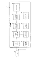
本発明の第7の実施形態について、図7を併せて参照しながら説明する。図7は、本発明の第7の実施形態に係る表示装置の回路構成例を示す図である。図7で例示する表示装置7は、図1の表示装置1の回路構成例であると言え、第1〜第6のいずれの実施形態にも適用できる。
(Seventh embodiment)
A seventh embodiment of the present invention will be described with reference to FIG. FIG. 7 is a diagram showing a circuit configuration example of a display device according to the seventh embodiment of the present invention. The display device 7 illustrated in FIG. 7 can be said to be a circuit configuration example of the display device 1 in FIG. 1 and can be applied to any of the first to sixth embodiments.
表示装置7は、USBコネクタ71、USB I/F(インターフェイス)コントローラ72、デジタル信号処理回路73、アナログ信号処理回路74、タッチセンサ75、DP/HDMIコネクタ76、画像処理回路77、パネルコントローラ78、及び表示パネル79を備えている。
The display device 7 includes a
ここで、パネルコントローラ78及び表示パネル79は、表示装置1の表示部13に対応している。また、アナログ信号処理回路74及びタッチセンサ75は、タッチセンサ12に対応している。USB I/Fコントローラ72、デジタル信号処理回路73、及び画像処理回路77は、制御部10に対応している。USBコネクタ71及びDP/HDMIコネクタ76は、通信部11に対応している。なお、図7においては、実線の矢印でタッチに関する信号、破線の矢印で映像に関する信号を示している。
Here, the
DP/HDMIコネクタ76は、DPケーブル又はHDMIケーブルと接続するためのI/Fである。DP/HDMIコネクタ76はDPケーブル又はHDMIケーブルを介してPC8に接続されている。DPケーブル又はHDMIケーブルを介して、PC8から映像信号が表示装置7に送信され、画像処理回路77に出力される。
The DP /
画像処理回路77は、このようにして外部から入力された映像信号を、表示パネル79に出力する信号に変換し、パネルコントローラ78に出力する回路であり、スケーラや黒帯付加/除去回路等も有している。画像処理回路77は、入力ソースの切り替え、音量調整などの表示装置7における各種設定の変更を受け付けるためのOSD画像を映像に重畳する処理も行う。パネルコントローラ78は、表示パネル79を駆動する駆動回路であり、表示パネル79はこの駆動により、画像処理回路77から出力された映像信号が示す映像を表示させる。
The
USBコネクタ71は、USBケーブルと接続するためのI/Fである。USBコネクタ71はUSBケーブルを介してPC8に接続されている。USBケーブルを介して、表示装置7から操作信号がPC8に送信される。USB I/Fコントローラ72は、USBコネクタ71にUSBケーブルを介して接続されたPC8との間で、USB規格のプロトコルに従って信号のやり取りを行う制御回路である。
The
タッチセンサ75は、図2を参照して説明したように、表示パネル79の表示領域に対応する範囲でマトリクス状に設けられた静電容量方式でマルチタッチ対応のセンサであり、表示パネル79の上に重ねて設けられている。アナログ信号処理回路74は、タッチセンサ75の駆動を行うと共に、タッチセンサ75からのアナログの検出信号を入力する回路である。この検出信号は、例えば、タッチ操作がなされた位置を特定する情報(入力座標情報)とその位置での静電容量の変化量の値とを示す信号である。アナログ信号処理回路74は、入力した検出信号をそのまま、或いはノイズ処理等を施してから、デジタル信号処理回路73に出力する。
As described with reference to FIG. 2, the
デジタル信号処理回路73は、アナログ信号処理回路74からアナログの検出信号を入力し、所定の演算を行い、デジタル情報としてのタッチ情報に変換し、USB I/Fコントローラ72に出力する回路である。この所定の演算は、図2を参照しながら説明したベゼル部17上の点であることの判定を含む。よって、デジタル信号処理回路73により、タッチ操作が表示パネル79の表示領域上でなされたのか、ベゼル部上でなされたのかについて区別できる。
The digital
USB I/Fコントローラ72は、入力されたタッチ情報が表示領域上でなされたものであるのか、ベゼル部上でなされたものであるのか、双方同時になされているものであるのかによって、タッチ情報の出力先を振り分ける。
The USB I /
USB I/Fコントローラ72は、表示領域上のみでなされたものである場合には、そのタッチ情報を通常の指によるタッチイベントとして、USBコネクタ71を介してPC8に出力する。PC8は、そのタッチ情報を反映させた映像信号をそれぞれDP/HDMIコネクタ76を介して送信し、最終的に表示パネル79での表示映像に反映されることになる。
If the USB I /
また、USB I/Fコントローラ72は、入力されたタッチ情報がベゼル部上でなされたものであって上記所定領域内でなされたと判定されている場合で、且つ表示領域上でのタッチに基づく他のタッチ情報の入力が同時にない場合には、ベゼル部上でなされたタッチ操作に関するタッチ情報を無視する。
Further, the USB I /
一方、USB I/Fコントローラ72は、入力されたタッチ情報がベゼル部上でなされたものであって上記所定領域内でなされたと判定されている場合で、且つ表示領域上で他のタッチ情報の入力も同時にある場合には、上記他のタッチ情報をペンイベントであるようにID及びフォーマットを作成又は修正して、USBコネクタ71を介してPC8に出力する。
On the other hand, the USB I /
ここで説明したUSB I/Fコントローラ72における処理は、図3で例示した処理に該当する処理である。なお、ベゼル部上の点であることの判定の一部又は全部をUSB I/Fコントローラ72側で実行するような構成を採用することもできる。
The process in the USB I /
本実施形態に係る表示装置7は、上述のような構成であるため、ベゼルタッチを検出するに際しては、例えば、従来のタッチセンサ75をそのまま用いて(従来のタッチセンサ75のハードウェア構成を変更することなく)、デジタル信号処理回路73、USB I/Fコントローラ72のいずれか一方又は双方に組み込まれたソフトウェア(ファームウェア)の変更のみで対応できる。
Since the display device 7 according to the present embodiment has the above-described configuration, when detecting a bezel touch, for example, the
(その他)
以上、本発明に係る表示装置について説明したが、処理の流れを説明したように、本発明は、画像を表示する表示部と、ユーザによる上記表示部の表示領域上でのタッチ操作を検出する静電容量方式でマルチタッチ対応のタッチセンサと、上記表示部の周囲に設けられたベゼル部と、を備えた表示装置におけるタッチ入力方法や、そのタッチ入力方法をコンピュータ(表示装置の制御部)に実行させるためのプログラムとしての形態も採り得る。
(Other)
Although the display device according to the present invention has been described above, as described in the flow of processing, the present invention detects a touch operation on the display area of the display unit and a display unit that displays an image. A touch input method in a display device comprising a capacitive touch sensor capable of multi-touch and a bezel portion provided around the display unit, and the touch input method of the computer (display device control unit) It is also possible to adopt a form as a program to be executed.
このタッチ入力方法は、上記タッチセンサが上記ベゼル部上にある所定領域内と上記表示領域内とで同時にタッチ操作を検出した場合、上記表示装置の制御部が、検出した上記表示領域内でのタッチ操作をペン入力モードで受け付ける。その他の応用例については、表示装置について説明した通りであり、その説明を省略する。 In the touch input method, when the touch sensor detects a touch operation simultaneously in a predetermined area on the bezel portion and in the display area, the control unit of the display device detects the touch operation in the detected display area. Touch operation is accepted in pen input mode. Other application examples are the same as those described for the display device, and description thereof is omitted.
上記プログラムは、換言すると、このタッチ入力方法を、上記表示部、上記タッチセンサ、及び上記ベゼル部を備えたコンピュータに実行させるためのプログラムである。すなわち、このプログラムは、上記コンピュータに、上記タッチセンサが上記ベゼル部上にある所定領域内と上記表示領域内とで同時にタッチ操作を検出した場合、検出した上記表示領域内でのタッチ操作をペン入力モードで受け付けるステップを実行させるためのプログラムである。その他の応用例については、表示装置について説明した通りであり、その説明を省略する。 In other words, the program is a program for causing a computer including the display unit, the touch sensor, and the bezel unit to execute the touch input method. That is, when the touch sensor simultaneously detects a touch operation in the predetermined area on the bezel portion and in the display area, the program causes the touch operation in the display area to be detected by the pen. It is a program for executing a step accepted in the input mode. Other application examples are the same as those described for the display device, and description thereof is omitted.
また、上記プログラムをコンピュータにより読み取り可能な記録媒体に記録したプログラム記録媒体としての形態についても容易に理解することができる。このコンピュータとしては、上述したように、汎用のPCに限らず、マイクロコンピュータやプログラム可能な汎用の集積回路/チップセットなど、様々な形態のコンピュータが適用できる。また、このプログラムは、可搬の記録媒体を介して流通させるに限らず、インターネット等のネットワークを介して、また放送波を介して流通させることもできる。ネットワークを介して受信するとは、外部サーバの記憶装置などに記録されたプログラムを受信することを指す。 In addition, it is possible to easily understand the form of a program recording medium in which the program is recorded on a computer-readable recording medium. As described above, the computer is not limited to a general-purpose PC, and various forms of computers such as a microcomputer and a programmable general-purpose integrated circuit / chip set can be applied. In addition, this program is not limited to be distributed via a portable recording medium, but can also be distributed via a network such as the Internet or via a broadcast wave. Receiving via a network refers to receiving a program recorded in a storage device of an external server.
1,7…表示装置、4…ペン、8…PC、10…制御部、11…通信部、12,75…タッチセンサ、12a…タッチパネルユニット、12b…外枠部分、12d…タッチパネル、13…表示部、13a…液晶ユニット、13b…液晶パネル、13c…光学シート、13d…導光板、13e…反射シート、13f…LED基板、14a…前面化粧パネル、14b…ベゼル領域部分、14d…表示領域部分、15a…背面シャーシ、15b…パネル固定部材、15c…LED基板固定部材、15d,15e…スペーサ、16a…背面キャビネット、16b…側面キャビネット、17…ベゼル部、17a…ペン領域、17b…ホバー領域、17c…筆圧調整領域、17d…消しゴム領域、17e…ペン反転領域、17f…任意イベント領域、71…USBコネクタ、72…USB I/Fコントローラ、73…デジタル信号処理回路、74…アナログ信号処理回路、76…DP/HDMIコネクタ、77…画像処理回路、78…パネルコントローラ、79…表示パネル。
DESCRIPTION OF SYMBOLS 1,7 ... Display apparatus, 4 ... Pen, 8 ... PC, 10 ... Control part, 11 ... Communication part, 12, 75 ... Touch sensor, 12a ... Touch panel unit, 12b ... Outer frame part, 12d ... Touch panel, 13 ... Display Part, 13a ... liquid crystal unit, 13b ... liquid crystal panel, 13c ... optical sheet, 13d ... light guide plate, 13e ... reflective sheet, 13f ... LED substrate, 14a ... front decorative panel, 14b ... bezel area part, 14d ... display area part, 15a ... Rear chassis, 15b ... Panel fixing member, 15c ... LED board fixing member, 15d, 15e ... Spacer, 16a ... Back cabinet, 16b ... Side cabinet, 17 ... Bezel part, 17a ... Pen area, 17b ... Hover area, 17c ... pen pressure adjustment area, 17d ... eraser area, 17e ... pen inversion area, 17f ... arbitrary event area, 71 USB connector, 72 ... USB I /
Claims (7)
前記タッチセンサが前記ベゼル部上にある所定領域内と前記表示領域内とで同時にタッチ操作を検出した場合、検出した前記表示領域内でのタッチ操作をペン入力モードで受け付ける制御部を、さらに備えたことを特徴とする表示装置。 A display unit that displays an image, a touch sensor that supports multi-touch using a capacitance method that detects a touch operation on a display area of the display unit by a user, a bezel unit provided around the display unit, A display device comprising:
When the touch sensor detects a touch operation in the predetermined area on the bezel part and in the display area at the same time, the control unit further accepts the detected touch operation in the display area in a pen input mode. A display device characterized by that.
前記制御部は、前記タッチセンサが前記第2の所定領域内と前記表示領域内とで同時にタッチ操作を検出した場合、検出した前記表示領域内でのタッチ操作を、前記第2の所定領域においてタッチ操作を検出した長手方向位置に対応した筆圧レベルによる入力操作として受け付けることを特徴とする請求項1又は2に記載の表示装置。 In the predetermined region, a second predetermined region that is a rectangular region having the same longitudinal direction as the bezel portion is defined,
When the touch sensor detects a touch operation in the second predetermined area and the display area at the same time, the control unit performs the detected touch operation in the display area in the second predetermined area. The display device according to claim 1, wherein the display device accepts an input operation based on a writing pressure level corresponding to the position in the longitudinal direction in which the touch operation is detected.
前記タッチセンサが前記ベゼル部上にある所定領域内と前記表示領域内とで同時にタッチ操作を検出した場合、前記表示装置の制御部が、検出した前記表示領域内でのタッチ操作をペン入力モードで受け付けることを特徴とするタッチ入力方法。 A display unit that displays an image, a touch sensor that supports multi-touch using a capacitance method that detects a touch operation on a display area of the display unit by a user, a bezel unit provided around the display unit, A touch input method in a display device comprising:
When the touch sensor detects a touch operation in the predetermined area on the bezel portion and in the display area at the same time, the control unit of the display device performs the touch operation in the detected display area in a pen input mode. The touch input method characterized by accepting in
Priority Applications (1)
| Application Number | Priority Date | Filing Date | Title |
|---|---|---|---|
| JP2013255690A JP2015114802A (en) | 2013-12-11 | 2013-12-11 | Display device and touch input method |
Applications Claiming Priority (1)
| Application Number | Priority Date | Filing Date | Title |
|---|---|---|---|
| JP2013255690A JP2015114802A (en) | 2013-12-11 | 2013-12-11 | Display device and touch input method |
Publications (1)
| Publication Number | Publication Date |
|---|---|
| JP2015114802A true JP2015114802A (en) | 2015-06-22 |
Family
ID=53528565
Family Applications (1)
| Application Number | Title | Priority Date | Filing Date |
|---|---|---|---|
| JP2013255690A Pending JP2015114802A (en) | 2013-12-11 | 2013-12-11 | Display device and touch input method |
Country Status (1)
| Country | Link |
|---|---|
| JP (1) | JP2015114802A (en) |
Cited By (1)
| Publication number | Priority date | Publication date | Assignee | Title |
|---|---|---|---|---|
| JP2020064404A (en) * | 2018-10-16 | 2020-04-23 | カシオ計算機株式会社 | Input device and electronic apparatus |
-
2013
- 2013-12-11 JP JP2013255690A patent/JP2015114802A/en active Pending
Cited By (2)
| Publication number | Priority date | Publication date | Assignee | Title |
|---|---|---|---|---|
| JP2020064404A (en) * | 2018-10-16 | 2020-04-23 | カシオ計算機株式会社 | Input device and electronic apparatus |
| JP7505860B2 (en) | 2018-10-16 | 2024-06-25 | カシオ計算機株式会社 | Input devices and electronic devices |
Similar Documents
| Publication | Publication Date | Title |
|---|---|---|
| US9400590B2 (en) | Method and electronic device for displaying a virtual button | |
| US9400581B2 (en) | Touch-sensitive button with two levels | |
| JP5066055B2 (en) | Image display device, image display method, and program | |
| US8289292B2 (en) | Electronic device with touch input function and touch input method thereof | |
| CN102870075B (en) | Portable electric appts and control method thereof | |
| US8836649B2 (en) | Information processing apparatus, information processing method, and program | |
| US10073585B2 (en) | Electronic device, storage medium and method for operating electronic device | |
| CN104007922B (en) | Method for providing feedback in response to user input and terminal implementing the method | |
| KR102168648B1 (en) | User terminal apparatus and control method thereof | |
| KR102028717B1 (en) | Flexible apparatus and control method thereof | |
| US10067666B2 (en) | User terminal device and method for controlling the same | |
| AU2013223015A1 (en) | Method and apparatus for moving contents in terminal | |
| JP2012133453A (en) | Information processing device, information processing method and program | |
| KR20150134674A (en) | User terminal device, and Method for controlling for User terminal device, and multimedia system thereof | |
| JP2013540330A (en) | Method and apparatus for recognizing gesture on display | |
| TWI514246B (en) | Methods for interacting with an electronic device by using a stylus comprising body having conductive portion and systems utilizing the same | |
| JP2015088085A (en) | Display device and display method | |
| CN103080890B (en) | Portable electric appts and control method thereof | |
| US9417724B2 (en) | Electronic apparatus | |
| US20130293495A1 (en) | Method for inputting touch and touch display apparatus | |
| KR20150111701A (en) | terminal apparatus and control method | |
| US20120151409A1 (en) | Electronic Apparatus and Display Control Method | |
| JP6352626B2 (en) | Display device and unlocking method | |
| US9857910B2 (en) | Method for controlling multiple touchscreens and electronic device | |
| JP2015114802A (en) | Display device and touch input method |