JP2015114676A - Operation confirmation system - Google Patents
Operation confirmation system Download PDFInfo
- Publication number
- JP2015114676A JP2015114676A JP2013253772A JP2013253772A JP2015114676A JP 2015114676 A JP2015114676 A JP 2015114676A JP 2013253772 A JP2013253772 A JP 2013253772A JP 2013253772 A JP2013253772 A JP 2013253772A JP 2015114676 A JP2015114676 A JP 2015114676A
- Authority
- JP
- Japan
- Prior art keywords
- work
- mark
- unit
- estimated
- confirmation system
- Prior art date
- Legal status (The legal status is an assumption and is not a legal conclusion. Google has not performed a legal analysis and makes no representation as to the accuracy of the status listed.)
- Granted
Links
Images
Classifications
-
- Y—GENERAL TAGGING OF NEW TECHNOLOGICAL DEVELOPMENTS; GENERAL TAGGING OF CROSS-SECTIONAL TECHNOLOGIES SPANNING OVER SEVERAL SECTIONS OF THE IPC; TECHNICAL SUBJECTS COVERED BY FORMER USPC CROSS-REFERENCE ART COLLECTIONS [XRACs] AND DIGESTS
- Y02—TECHNOLOGIES OR APPLICATIONS FOR MITIGATION OR ADAPTATION AGAINST CLIMATE CHANGE
- Y02P—CLIMATE CHANGE MITIGATION TECHNOLOGIES IN THE PRODUCTION OR PROCESSING OF GOODS
- Y02P90/00—Enabling technologies with a potential contribution to greenhouse gas [GHG] emissions mitigation
- Y02P90/30—Computing systems specially adapted for manufacturing
Landscapes
- General Factory Administration (AREA)
- Management, Administration, Business Operations System, And Electronic Commerce (AREA)
Abstract
Description
この発明は、例えば生産ラインなどにおいて、作業内容を簡便に確認することができる作業確認システムに関するものである。 The present invention relates to a work confirmation system capable of easily confirming work contents in, for example, a production line.
従来の作業確認システムは、道具にマークを取り付けて、画像処理によりマークを検出し、道具の位置方向を特定する手段によって、作業内容を確認するものである(例えば、特許文献1参照)。また、他の従来の作業確認システムは、締付具に発光器を取り付けて、画像処理により発光器を検出し、締付作業の位置を特定する手段によって、作業内容を確認するものである(例えば、特許文献2参照)。 The conventional work confirmation system confirms the work contents by attaching a mark to a tool, detecting the mark by image processing, and specifying the position direction of the tool (for example, refer to Patent Document 1). In another conventional work confirmation system, a light emitter is attached to a fastener, the light emitter is detected by image processing, and the work content is confirmed by means for specifying the position of the tightening work ( For example, see Patent Document 2).
生産ラインで製品を組み立てる作業においては様々な形状の道具を使用する場合がある。従来の作業確認システムでは、ドライバ、レンチの他に、ニッパ、ペンチ、ハサミ、ハケ、ペンなどを使用することがある。また、道具を使用しない作業がある。例えば、コネクタの接続、部材の嵌め合わせ、スイッチの切替といった作業である。従来の作業確認システムのように道具に対してマークや発光器を取り付ける方法では、道具の形状によって異なる取り付け方を考案し、画像処理で検出できることを検証するといった準備作業が必要である。その他にも、小型の道具を使用する場合にはマークや発光器を取り付けること自体が難しい、道具を使用しない場合に対しては適用できないといった問題点があった。 There are cases where tools of various shapes are used in assembling products on the production line. Conventional work confirmation systems may use nippers, pliers, scissors, brushes, pens, etc. in addition to drivers and wrench. There is also work that does not use tools. For example, such operations as connector connection, member fitting, and switch switching. In a method of attaching a mark or a light emitter to a tool as in a conventional work confirmation system, a preparation work is required to devise a different attachment method depending on the shape of the tool and verify that it can be detected by image processing. In addition, there are problems that it is difficult to attach a mark or a light emitter when using a small tool, and that it is not applicable when a tool is not used.
この発明は上記のような課題を解決するためになされたものであり、作業における様々な形状の道具を使用した作業や、道具を使用しない作業に対しても、作業内容を確認できる作業確認システムを提供することを目的とする。 The present invention has been made to solve the above-described problems, and is a work confirmation system capable of confirming work contents even for work using tools of various shapes in work and work without using tools. The purpose is to provide.
この発明の作業確認システムは、
作業者が行う作業内容を確認する作業確認システムにおいて、
前記作業者が手に装着し、前記手の甲から指先にかけての方向性があるマークを有するグローブと、
前記グローブの前記マークを撮影する撮像機器と、
前記撮像機器にて撮影した前記マークの画像データと前記作業内容とを比較して合否判定を行う制御機器とを備えたものである。
The work confirmation system of this invention is
In the work confirmation system that confirms the work content performed by the worker,
A glove having a mark attached to the hand by the operator and having directionality from the back of the hand to a fingertip;
An imaging device for photographing the mark of the globe;
And a control device that performs pass / fail judgment by comparing the image data of the mark photographed by the imaging device and the work content.
この発明の作業確認システムは、上記のように構成されているため、
グローブのマークを撮影することにより、作業内容を簡便に確認することができる。
Since the work confirmation system of the present invention is configured as described above,
By photographing the glove mark, the work content can be easily confirmed.
実施の形態1.
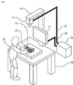
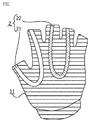
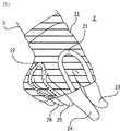
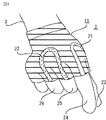
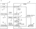
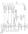
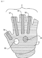
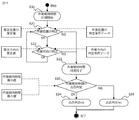
以下、本願発明の実施の形態について説明する。図1はこの発明の実施の形態1における作業確認システムの構成を示す斜視図、図2は図1に示した作業確認システムのグローブの構成を示した図、図3および図4は図2に示したグローブを装着した際の動作を示した図、図5は図1に示した作業確認システムの制御機器および表示器の構成を示すブロック図、図6および図7および図12は図1に示した作業確認システムの動作を示すフローチャート、図8から図11および図13および図14は図1に示した作業確認システムの画像データの例を示した図、図15は図1に示した作業確認システムの画面状態の例を示した図、図16および図17は図1に示した作業確認システムのグローブの他の構成を示した図である。
Embodiments of the present invention will be described below. 1 is a perspective view showing a configuration of a work confirmation system according to
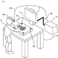
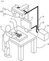
図において、この作業確認システムは、作業者13が行う作業内容を確認するものである。作業者13が手に装着し、手の甲から指先にかけての方向性があるマーク2を有するグローブ11と、グローブ11のマーク2を撮影する撮像機器15と、撮像機器15にて撮影したマーク2の画像データと作業内容とを比較して合否判定を行う制御機器18と、作業内容および合否判定を表示する表示器17とを備える。
In the figure, this work confirmation system confirms the work contents performed by the
本実施の形態1において、作業者13が行う作業内容は、例えば、作業机14上に作業対象物12が載置されている状態にて、作業者13が手を使用して行う作業を行うものである。尚、この作業内容は、作業者13の手のみにて行う場合、また、作業者13が手に工具などを持ち行う場合のいずれにも対応することができる。図1においては、例として、作業者13が手にグローブ11を装着した状態で、表示器17に表示された作業内容に従って、作業対象物12に対して作業をしている状況を示しているものである。また、作業対象物12は、例えば、機器や電子回路基板などである。
In the first embodiment, the work content performed by the
撮像機器15と制御機器18とは画像信号入力線19にて接続され、表示器17と制御機器18とは表示信号出力線20にて接続されている。撮像機器15は、支持台16を介して作業机14に設置されており、例えば、CCDカメラやCMOSカメラなどの一般的な撮像機器を用いる。撮像機器15の設置位置は、作業対象物12の上方に設置する例を示したが、作業中にグローブ11のマーク2が撮影可能な位置であればよく、例えば、斜め上方や横方向に設置してもよい。
The
画像信号入力線19は、撮像機器15と制御機器18との入出力インタフェースに対応したケーブル線にて構成されている。表示信号出力線20は、表示器17と制御機器18との入出力インタフェースに対応したケーブル線にて構成されている。これら画像信号入力線19および表示信号出力線20は、例えばUSBケーブル、VGAケーブル、HDMI(登録商標)ケーブル、同軸ケーブル、Ethernet(登録商標)用ケーブルなどにて構成されている。
The image
表示器17は、作業机14に設置されており、例えば液晶モニタなどの一般的な表示器で、本実施の形態1においては、タッチパネル入力機能を有し操作入力機器を兼ねるものとする。尚、表示器17に入力機能がない場合には、操作入力機器としてキーボードやマウス、またはスイッチなどを制御機器18に接続することにより可能となる。また、表示器17は支持台16に固定して設置する例を示したがこれに限られることはなく、作業者13から表示内容を確認できればよく、他の例としては、表示器17を作業机14の上面に設置ことが考えられる。
The
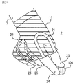
グローブ11のマーク2は、作業者13の手の甲から指先にかけての方向性を有するものであればよく、色、明度、形状、および大きさのいずれか少なくとも1つを用いて、この方向性を有するように構成されているものである。具体的には、図2、図3、図4に示すように、作業者13がグローブ11を右手3に装着した場合、右手3の甲の側に、親指23および人差し指24のペアに対応するマーク21および中指25および薬指26のペアに対応するマーク22をそれぞれ異なる色や模様として構成する。尚、ここでは右手3用のグローブ11を示したが、左手用のグローブについても、同様に各マークを構成することにより対応することができるため、その説明は適宜省略する。
The
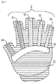
グローブ11はどのような材質であってもよい。ここでは、グローブ11は防塵布製であって、マーク2部分以外は灰色、親指23と人差し指24とのペアのマーク21は黄色、中指25と薬指26とのペアのマーク22は緑色に塗色されているとする。グローブ11のマーク2の他の例としては、図16に示したように、各指に対応した異なる色や模様の親指用のマーク50、人差し指用のマーク51、中指用のマーク52、薬指用のマーク53、小指用のマーク54およびそれら各マーク50〜54を接続する手の甲側のマーク55を備える。また、他の例は、図17に示したように、マーク2として、各指に対応した同色同模様の帯状の親指用、人差し指用、中指用、薬指用のマーク56、57、58、59と、手の甲側の色や模様の異なる2つのマーク60、61とがあるものなどの形態が考えられる。図16および図17のようなマーク2によれば、手の甲から指先にかけての方向性があるマーク2が形成されることとなり、図2に示したグローブ11と同様に処理することが可能となる。
The
ここではグローブ11として指先の開いたものを示したが、指先を覆うグローブ11としてもよい。またマーク2の形状は主に帯状を示したが、細線や楕円などの方向性のある形状や、複数の円や矩形など方向性を持たない形状を連ねて方向性を持たせた形状としてもよい。また、右手用のグローブ11を示しているが、左手用であってもよく、右手用と左手用のグローブを同時に使用してもよい。
Here, a
制御機器18は、例えば、パーソナルコンピュータ、産業用コンピュータ、マイコンボード、プログラマブルロジックコントローラなどにて構成され、以下の部分を備える。図5に示すように、制御機器18は、作業定義部31と、作業指示部32と、画像入力部33と、画像処理部34と、作業確認部35と、結果記録部36とから構成されている。表示器17は、設定画面41と、作業指示画面42と、作業結果画面43との画面が表示可能に形成されている。
The
作業定義部31は、各作業内容に対応した作業指示データ、および、各作業内容を判定するための作業位置および作業方向の判定条件データを格納している。さらに、表示器17に表示される設定画面41から作業者13の操作によって入力されるデータ、例えば図15に示す、作業の中断を設定する作業中断ボタン98および作業対象物の変更を設定する作業対象変更ボタン97などを設定する設定機能、作業指示部32に作業指示データを送信する出力機能を有している。作業指示データは、作業指示図、作業指示メッセージ、タイムアウト時間、検出範囲の判定条件を含むものである。例えば、作業指示図にはJPEG形式画像のファイル名、作業指示メッセージはUnicode形式の文字列、タイムアウト時間には秒単位の浮動小数点型の数値、検出範囲の判定条件には基準矩形の左上と右上を示す座標値および許容誤差値が示されている。
The
作業位置の判定条件データは、撮像機器15により取得する画像における横軸X、縦軸Y方向の座標値および許容誤差円の許容半径Rを含むものである。例えばX、Yは画像の左下を原点としたピクセル単位の絶対座標値として定義し、Rはピクセル単位の相対座標値として定義する。作業方向の判定条件データは、撮像機器15による取得する画像の平面上の角度θおよび許容誤差の角度の絶対値φを含むものである。例えば、θは画像の横軸右方向を0度として360度までの値で定義し、φはθを基準とした相対角度を定義する。
The work position determination condition data includes the coordinate values in the horizontal axis X and vertical axis Y directions and the allowable radius R of the allowable error circle in the image acquired by the
作業指示部32は、作業定義部31から作業指示データを取得し、表示器17の作業指示画面42に作業指示データを表示する。画像入力部33は、撮像機器15から画像データを入力する。例えば画像を処理するドライバソフトウェアのAPIを使用することで、ビットマップ画像として入力する。画像処理部34は、画像入力部33から画像データを取得し、画像データに写るグローブ11のマーク2を検出して、マーク2の推定位置および推定方向の推定値を検出する。
The
作業確認部35は、画像処理部34から推定位置および推定方向の推定値を取得し、作業定義部31から作業位置および作業方向の判定条件データを取得して、推定位置および推定方向の推定値が判定条件データの許容誤差内であるか否かの合否判定を行い、その合否判定結果を表示器17の作業結果画面43に表示する。結果記録部36は、作業結果のデータを記録する。
The
次に上記のように構成された実施の形態1の作業確認システムの動作について説明する。本発明における、作業確認システムとは、作業状況の外観の画像を撮像機器15により取得して、制御機器18により画像処理を行い、グローブ11の有するマーク2を検出して推定位置と推定方向との推定を行った後に、それらの合否判定を行い表示器17に判定結果を出力するものである。以下、その詳細な動作について説明する。
Next, the operation of the work confirmation system of the first embodiment configured as described above will be described. In the present invention, the work confirmation system acquires an image of the appearance of a work situation with the
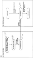
本実施の形態1においては、ある作業対象物12について行う複数の作業内容について、作業指示と作業確認とを繰り返し、作業結果を判定するものである。まず、作業定義部31から作業指示データを取得して作業指示準備を行う(図6のステップS1)。次に、作業指示データを作業指示部32に転送し、作業指示部32が作業指示画面42に出力して作業指示データの表示を行う(図6のステップS2)。
In the first embodiment, a work instruction and work confirmation are repeated for a plurality of work contents to be performed on a
次に、作業者13は作業指示画面42に表示される作業指示データを確認して、グローブ11を装着した状態で、作業対象物12に対して作業を行う。次に、作業者13の作業中に、撮像機器15はグローブ11の撮影を行い、その撮影の画像データを画像信号入力線19を介して画像入力部33に入力して当該画像データを取得して画像入力を行う(図6のステップS3)。次に、画像データを画像処理部34に転送し、グローブ11のマーク2の推定位置および推定方向の推定値を取得する画像処理を行う(図6のステップS4)。
Next, the
次に、作業確認部35に推定位置および推定方向の推定値を転送し、作業確認部35は作業位置および作業方向の作業判定データを比較して合否判定して作業確認を行う(図6のステップS5)。そして、合否判定がNGの場合は、タイムアウトもしくは中断であるか否かの判断を行う(図6のステップS6)。そして、タイムアウトもしくは中断であれば、表示器17の作業結果画面43に作業中断メッセージを表示する(図6のステップS9)。
Next, the estimated values of the estimated position and the estimated direction are transferred to the
また、ステップS5にて合否判定がOKの場合には、作業対象物12に対する残りの作業の有無を確認するため、全作業が完了したか否かを判断する(図6のステップS7)。そして、残りの作業があり、全作業が終了していない場合には、ステップS1に戻り、上記に示した処理を繰り返す。また、全作業が終了している場合には、表示器17の作業結果画面43に作業完了メッセージを表示する(図6のステップS8)。次に、この作業の作業結果を結果記録部36に出力して格納する(図6のステップS10)。また、ステップS6にて、タイムアウトもしくは中断でなければ、リトライとして、上記ステップS3からの処理を繰り返す。
If the pass / fail determination is OK in step S5, it is determined whether or not all work has been completed in order to check whether or not there is any remaining work on the work object 12 (step S7 in FIG. 6). If there are remaining tasks and all the tasks have not been completed, the process returns to step S1 and the above-described processing is repeated. If all the work has been completed, a work completion message is displayed on the
ステップS8の作業結果出力は、具体的には、作業対象物12に対する各作業の作業開始日時と作業終了日時、作業位置データ、作業方向データ、作業位置と作業方向の合否判定結果を、作業結果データとして、結果記録部36に格納し、その一部を作業結果画面43に表示するものである。
Specifically, the output of the work result in step S8 includes the work start date and time and the work end date and time of each work on the
尚、タイムアウトとは、この繰り返し処理の間に合否判定値がNGのまま、作業指示データに含まれるタイムアウト時間を超過した場合に、タイムアウトがありとなり、そうでなければタイムアウトが無しとなる。また、中断とは、この繰り返し処理の間に作業者13が、作業指示画面42に表示している作業中断ボタン98を押すことで中断がありとなり、そうでなければ中断が無しとなる。尚、作業中断ボタン98には、キーボードやスイッチなど、他の入力手段を用いてもよい。
The time-out is a time-out when the pass / fail judgment value remains NG during this repetitive processing and the time-out time included in the work instruction data is exceeded, otherwise there is no time-out. Also, the interruption means that the
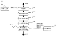
次に、画像処理部34の画像処理の内容について図7のフローチャートに基づいて説明する。まず、制御機器18の画像入力(図6のステップS3)および画像処理(図6のステップS4)の制御に従い、画像入力部33から画像データを取得し、画像データ70に含まれるノイズを除去する前処理を行う(図7のステップS11)。この前処理は、例えば、画像データの縮小拡大処理や、ブラーフィルタによるぼかし処理、メディアンフィルタによる処理など一般的な画像処理方法における前処理を行うものである。
Next, the contents of the image processing of the
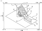
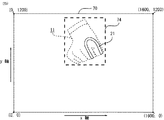
次に、グローブ11の近辺のみを検出範囲74として設定する(図7のステップS12)。これは、マーク2の検出時に、グローブ11以外の場所の画像データ70を使用して、誤検出することを防止するためである。具体的には、200万画素のデジタルカメラを使用してx軸方向1600画素、y軸方向1200画素の画像を取得した場合の画像データ70を図8に示すように入力した場合について説明する。
Next, only the vicinity of the
図8は、作業対象物12として、基板73上のコネクタ受け部72に対して、コネクタ71を挿入する作業状況の画像データ70を示している。この画像データ70からグローブ11のマーク2以外の部分の色を抽出して、グローブ11の外形を求め、その外形の境界部分にマーク2がある場合を考慮して、その外形から50画素ほど上下左右に広げた矩形領域を検出範囲74として設定する。
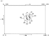
FIG. 8 shows
尚、ここではグローブ11の色を使用して設定しているが、画像データ70からグローブ11の外形を抽出できる他の特徴、例えば明度や模様を使用してもよい。また、検出範囲74の設定を行わなくとも誤検出が発生しない場合は、検出範囲74の設定する処理は省略して、画像データ70の全体を検出範囲としてもよい。さらに、検出範囲74の設定は、グローブ11の外形寸法が許容基準内にあるかを判定することで、グローブ11と撮像機器15との間に適正な距離が取られておらず、画像データ70上にグローブ11が大きく写ったり、逆に小さく写ったりするような状況でマーク2の検出を続けることを防止することにもなる。
Although the setting is made using the color of the
次に、検出範囲74からマーク2の親指23と人差し指24とのペアのマーク21および中指25と薬指26とのペアのマーク22の、各色あるいは各模様等のマーク2の特徴から各マーク21、22を抽出する(図7のステップS13)。図9は、図8においてこのステップS13を行い、親指23と人差し指24とのペアのマーク21が抽出された状況を示す。
Next, from the
例えば、色によりマーク2の抽出を行う場合には、予めマーク2の色に該当するピクセル値の範囲を判定条件として設定しておき、検出範囲74内で判定条件に該当するものを抽出するといった方法で実施することができる。また、例えば、模様によりマーク2の抽出を行う場合には、予めマーク2の模様に該当する画像片を設定しておき、検出範囲74内の各座標において所定の角度回転させた画像片との比較処理を行って一致部分を得ることにより抽出するといった方法で実施することができる。
For example, when extracting the
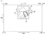
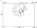
次に、マーク21の形状の抽出を行う(図7のステップS14)。具体的には、図10に示す例のように、先に抽出した図9に示すマーク21に対して、画像処理方法として一般的な2値化処理と細線化処理とを行い、マーク21の帯の幅方向の中心を結ぶ線分80を得る。次に、マーク21の推定位置および推定方向の推定値を検出する(図7のステップS15)。具体的には、図10にて抽出したマーク21の線分80を走査し、図10に示すように均等な長さの4つの線分81、82、83、84に分割した後、図11のように両端にあたる線分81、84の直線近似を求めることで、線分81、84の各中点86、88を基準に、マーク21の形状の指先に向いた、有向線分85、87をそれぞれ求める。
Next, the shape of the
尚、マーク2が図2に示す以外の、図17や図18に示したマーク2の形状であって、推定位置および推定方向の推定値を求める場合であれば、マーク2形状の抽出で得た線分を各々の中点で2つの線分に分割し、手の甲側のマーク2から遠い方、つまり指先側の線分を有向線分として求めることで同様に行うことができる。
If the
そして、有向線分85、87のそれぞれの中点86、88を推定位置の推定値、有向線分85、87のそれぞれの方向を推定方向の推定値とする。ここでは、推定位置は(x軸の画素位置、y軸の画素位置)の組で表す。また、推定方向はx軸方向を0として反時計回りを正とした角度で表す。このように求めた推定位置および推定方向の推定値を作業確認部35に送信する。
The
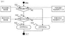
次に、作業確認部35の合否判定について図12のフローチャートに基づいて説明する。まず、作業確認部35は、推定位置の推定値と、作業定義部31から取得する作業位置の判定条件データとを比較して判定を行う(図12のステップS21)。具体的には、図13に示すように、作業定義部31から作業位置の判定条件データとしての基準有向線分201、203と、作業位置の許容半径Rを取得し、それぞれの基準有向線分201、203の中点202、204を中心とした作業位置の許容半径Rの円を、基準有向線分201の中点202の判定条件205、基準有向線分203の中点204の判定条件206とする。そして、推定位置の推定値として取得済の各有向線分85、87の各中点86、88が、それぞれの判定条件205、206の範囲内であれば、作業位置の判定をOKとして次のステップに進み、そうでなければNGとして合否判定NG(図12のステップS24)となる。
Next, the pass / fail determination of the
さらに具体的には、推定位置の推定値が(312、513)つまりx=312、y=513であり、作業位置の判定条件データの座標値X=310、Y=510、許容誤差の許容半径R=10であったとすれば、
√((x−X)×(x−X)+(y−Y)×(y−Y))≒3.6≦R
となり判定がOKとなる。
More specifically, the estimated value of the estimated position is (312 and 513), that is, x = 312 and y = 513, the coordinate values X = 310 and Y = 510 of the work position determination condition data, and the allowable radius of allowable error If R = 10,
√ ((x−X) × (x−X) + (y−Y) × (y−Y)) ≈3.6 ≦ R
The determination is OK.
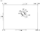
次に、作業確認部35は、推定方向の推定値と、作業定義部31から取得する作業方向の判定条件データとを比較して判定を行う(図12のステップS22)。具体的には、図14に示すように、作業定義部31から、作業方向の許容角度を取得し、それぞれの基準有向線分207、208を基準に、作業方向の許容角度を当てはめ、各基準有向線分207、208の方向の判定条件209、210とする。そして、推定方向の推定値として取得済の各有向線分85、87の方向が、各基準有向線分207、208の方向の判定条件209、210の範囲内であれば、作業方向の判定をOKとして、合否判定OKとなり(図12のステップS23)、そうでなければNGとして合否判定NG(図12のステップS24)となる。
Next, the
さらに、具体的には、例えば作業方向の許容角度の基準値θと、許容誤差の相対角度φ、推定方向の推定値をpとすれば、
|p−θ|≦φ
となり判定がOKとなる。
More specifically, for example, if the reference value θ of the allowable angle in the work direction, the relative angle φ of the allowable error, and the estimated value of the estimated direction are p,
| P-θ | ≦ φ
The determination is OK.
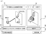
そして、作業位置および作業方向の合否判定の結果を、表示器17の作業結果画面43に出力する。作業指示画面42および作業結果画面43は、表示器17に表示し、作業者13が確認する。各画面は別の画面として表示もよいし、統合した一つの画面として表示してもよい。図15に作業指示画面42および作業結果画面43を統合して一つの画面として表示器17に表示する例を示す。作業名91、作業指示図92、作業指示メッセージ93を表示することで、作業者13に作業内容を伝える。
Then, the result of pass / fail determination of the work position and work direction is output to the
作業指示図92には、使用する部材や作業対象物12とグローブ11との位置関係を図示する。ここでは、グローブ11全体の代わりに、親指人差し指ペアのマーク21のみを表示している。さらに、組立台数の目標/実績94、画像データ95、作業確認状態表示96によって作業者13に作業状況および作業結果を伝える。画像データ95には、画像入力部33が入力した画像データを表示する。作業確認状態表示96には、作業確認部35の出力する作業位置および作業方向の合否判定結果や、作業中の状況を示すメッセージを表示する。
The work instruction diagram 92 illustrates the positional relationship between the member to be used and the
作業対象変更ボタン97は、作業対象物12の種類を変更することを制御機器18に通知し、作業対象の選択画面に推移して、作業対象物12の種類を選択することで、作業対象を変更することができる。これは、作業定義部31には予め作業対象物12の種類に対応した作業指示データが蓄積されており、作業対象変更ボタン97を選択した場合には、作業定義部31から必要となる作業指示データを取得して、作業名91および作業指示図92の表示内容を変更する。
The work
上記のように構成された実施の形態1の作業確認システムは、作業員の装着したグローブのマークにより作業内容の合否判定を行うことができるため、組立作業における、様々な形状の道具を使用した作業や、道具を使用しない作業に対しても、作業内容を確認することができる。また、作業位置および作業方向を確認することにより作業内容を確認および改善点を確認することができる。
Since the work confirmation system according to
実施の形態2.
図18はこの発明の実施の形態2における作業確認システムの作業確認部の動作を示したフローチャートである。本実施の形態2における作業確認部35は、作業位置および作業方向の判定の際に、作業位置および作業方向の両者の判定がOKとなる状態が維持される時間(作業位置、または作業方向の両者の判定がNGとなるまでの時間)である作業維持時間を計測し、作業指示データに予め設定した作業維持時間の下限値および作業維持時間の上限値の間である場合に、合否判定値をOKとし、そうでない場合に合否判定値をNGとするものである。
FIG. 18 is a flowchart showing the operation of the work confirmation unit of the work confirmation system according to
よって、本実施の形態2における作業定義部31の作業指示データには、作業指示図、作業指示メッセージ、タイムアウト時間、検出範囲の判定条件に加えて、作業維持時間の下限値および作業維持時間の上限値を含むものとする。例えば、作業維持時間の下限値および上限値はそれぞれ、秒単位の浮動小数点数の数値で表すものとする。他の構成は上記実施の形態1であるためその説明は適宜省略する。
Therefore, in the work instruction data of the
次に実施の形態2における作業確認システムの動作について説明する。作業確認部35の以下に示す動作以外は、上記各実施の形態と同様であるためその説明を適宜省略する。作業確認部35は、処理の最初に作業維持時間の計測を開始する(図18のステップS31)。次に、上記実施の形態1と同様に、作業位置の判定(図18のステップS21)、および、作業方向の判定を行う(図18のステップS22)。
Next, the operation of the work confirmation system in the second embodiment will be described. Since the operations other than those described below of the
そして、ステップS21およびステップS22にて、判定がOKの場合には、再びステップS21に戻り、上記に示した動作を繰り返す。また、ステップS21およびステップS22にて、判定がNGの場合には、作業が終了したと判断し、作業維持時間の測定を完了する(図18のステップS32)。すなわち、作業位置および作業方向の判定がNGとなるのは、作業内容の作業位置および作業方向から外れたことを示し、作業内容が終了した場合、または、次の作業内容へ移る場合、または、作業内容が合致していない場合などが考えられる。 In step S21 and step S22, if the determination is OK, the process returns to step S21 again and the above-described operation is repeated. If the determination at step S21 and step S22 is NG, it is determined that the work has been completed, and the measurement of the work maintenance time is completed (step S32 in FIG. 18). That is, the determination of the work position and the work direction is NG, which indicates that the work content has deviated from the work position and the work direction, and when the work content is completed, or when moving to the next work content, or A case where the work contents do not match is considered.
次に、作業定義部31に格納されている作業維持時間の最小値および作業維持時間の最大値から作業維持時間の合否判定を行う(図18のステップS33)。そして、判定がOKの場合には、作業判定がOKとなる。また、判定がNGの場合には、作業判定がNGと判定され作業判定を終了する。 Next, the pass / fail determination of the work maintenance time is performed from the minimum value of the work maintenance time and the maximum value of the work maintenance time stored in the work definition unit 31 (step S33 in FIG. 18). If the determination is OK, the work determination is OK. If the determination is NG, the work determination is NG and the work determination ends.
上記のように構成された実施の形態2の作業確認システムによれば、上記実施の形態1と同様の効果を奏するのはもちろんのこと、作業維持時間を判定することができるので、作業維持時間が短すぎる場合や長すぎる場合に作業完了と見なさず、より正確に作業内容を確認することができる。 According to the work confirmation system of the second embodiment configured as described above, the work maintenance time can be determined as well as the same effect as the first embodiment. If it is too short or too long, it is not regarded as work completion, and the work content can be confirmed more accurately.
実施の形態3.
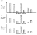
図19はこの発明の実施の形態3における作業確認システムの表示器に表示される表示例を示した図である。本実施の形態3においては、作業確認システムの作業確認は上記各実施の形態と同様に行うことができるためその説明は適宜省略し、本実施の形態3においては、作業結果を用いる作業分析部を備えるものについて説明する。まず、作業分析部は、結果記録部36の作業結果データから、複数の作業対象物12に対する各作業内容の開始時刻と各作業内容の終了時刻とを取得する。次に、各終了時刻と各開始時刻との差から各作業内容の各作業時間をそれぞれ求める。次に、複数の作業対象物12に対する標準偏差を計算し、各作業の時系列順を横軸とし、作業時間の標準偏差を縦軸とした棒グラフを求め、表示器17に表示する(図19(a))。
FIG. 19 is a diagram showing a display example displayed on the display of the work confirmation system according to
また、各作業内容の推定位置の標準偏差および推定方向の標準偏差をそれぞれ求めて、各作業内容の時系列順を横軸とし、各作業内容の推定位置の標準偏差および推定方向の標準偏差を縦軸とした棒グラフを求めて、表示器17に表示する(図19(b)、(c))。このようなグラフを表示することで、一連の作業の中で、作業時間が長いものや、その標準偏差が大きいもの、推定位置や推定方向の標準偏差の大きいものを抽出して、改善すべき作業を明らかにすることができる。 In addition, the standard deviation of the estimated position of each work content and the standard deviation of the estimated direction are obtained, respectively, and the time series order of each work content is taken as the horizontal axis, and the standard deviation of the estimated position of each work content and the standard deviation of the estimated direction are calculated. A bar graph with the vertical axis is obtained and displayed on the display 17 (FIGS. 19B and 19C). By displaying such a graph, in the series of work, those that have a long work time, those that have a large standard deviation, and those that have a large standard deviation of the estimated position and direction should be extracted and improved. Can clarify the work.
上記のように構成された実施の形態3の作業確認システムによれば、上記各実施の形態と同様の効果を奏するのはもちろんのこと、結果記録部に蓄積された推定位置の標準偏差、推定方向の標準偏差、および、推定時間の標準偏差を確認することができる。 According to the work confirmation system of the third embodiment configured as described above, the standard deviation of the estimated position accumulated in the result recording unit, as well as the effects similar to those of the above-described embodiments can be obtained. The standard deviation of the direction and the standard deviation of the estimated time can be confirmed.
実施の形態4.
本実施の形態4においては、制御機器18に、結果記録部36に蓄積された作業結果データの中から見本となる作業データを選択して、見本作業データとして作業定義部31に登録する見本作業選択部を備える例について説明する。この場合、画像入力(図6のステップS3)時において、入力した画像データを結果記録部36の作業結果データに含めて記録する。この画像データの記録は、例えば0.5秒などの一定間隔で行い、ビットマップ画像または動画としてMJPEGなどの各種の圧縮処理を用いて記録する。他の構成は上記各実施の形態と同様であるためその説明は適宜省略する。
Embodiment 4 FIG.
In the fourth embodiment, sample work data selected as work data from the work result data stored in the
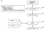
次に上記のように構成された実施の形態4における作業確認システムの動作について説明する。見本作業選択部の以下に示す動作以外は、上記各実施の形態と同様であるためその説明を適宜省略する。見本作業選択部は、結果記録部36の作業結果データの内、作業時間の長さが最適なもの、または、作業時間の標準偏差が最適なもの、または、推定位置および推定方向の推定値の標準偏差が最適なものを見本作業として選択する(図20のステップS40)。次に、この選択した作業結果データを見本作業データとして作業定義部31に登録する(図20のステップS41)。
Next, the operation of the work confirmation system according to Embodiment 4 configured as described above will be described. The operations other than those described below of the sample work selection unit are the same as those in each of the above embodiments, and thus the description thereof is omitted as appropriate. The sample work selection unit has the optimum work time length among the work result data of the
次に、作業指示部32は、作業定義部31から作業指示データおよび見本作業データを取得する(図20のステップS42)。次に、表示器17の作業指示画面42に、作業指示データおよび見本作業データの両者を、交互に、あるいは同時に表示する(図20のステップS43)。例えば作業指示データは、作業指示図および作業指示メッセージ、見本作業データは、見本作業データのビットマップ画像または動画を表示するものである。これにより、作業者13に見本作業データを示すことができる。
Next, the
上記のように構成された実施の形態4の作業確認システムによれば、上記各実施の形態と同様の効果を奏するのはもちろんこと、見本作業データを表示することができるため、作業者に作業内容の改善を促すことができる。 According to the work confirmation system of the fourth embodiment configured as described above, the sample work data can be displayed as well as the same effects as those of the above-described embodiments. The content can be improved.
実施の形態5.
上記各実施の形態においては、グローブを装着する作業者の個人差に対応する場合については特に示していないが、本実施の形態5においては、作業者の個人差に対応する場合について説明する。図21はこの発明の実施の形態5における作業確認システムの個人差補正用マークの構成を示す図、図22はこの発明の実施の形態5における作業確認システムの動作を示したフローチャートである。図において、上記各実施の形態と同様の部分は同一符号を付して説明を省略する。個人差補正用マーク100は、個人差を補正するための処理を行うためのものであり、例えば色、輝度、模様に特徴があり画像処理部34により一般的な画像処理方法で容易に検出できるようなものある。例えば、赤色の樹脂製球が考えられる。
In each of the above embodiments, the case corresponding to the individual difference of the worker wearing the glove is not particularly shown, but in the
本実施の形態5において作業定義部31は、作業指示データとして、作業指示図、作業指示メッセージ、タイムアウト時間、検出範囲の判定条件に加えて、作業位置の基準値、作業者13の作業位置の個人差補正値を含むものとする。例えば、作業位置の基準値および個人差補正値はピクセル単位の長さとする。そして、個人差補正値は、作業者13を識別する文字列をキーとして、各キーに対応した値を保持する辞書形式のデータ構造に格納することにより、作業者13毎に個人差補正値を格納するものである。
In the fifth embodiment, the
次に上記のように構成された実施の形態5における作業確認システムの動作について説明する。作業内容の作業位置の基準値および作業者13の作業位置の個人差補正値を含める動作以外は、上記各実施の形態と同様であるためその説明を適宜省略する。まず、作業者13によって、図21に示すように、個人差補正用マーク100を親指23と人差し指24とによって保持させる。そしてこの状態を撮像機器15にて撮影して作業者13が個人差補正用マーク100を保持した状態のマーク2を撮影した補正用画像データを取得する(図22のステップS50)。
Next, the operation of the work confirmation system according to
次に、画像処理部34によって個人差補正用マーク100の検出位置から作業位置までの長さを求め、この長さを作業位置の個人差補正値hを検出する(図22のステップS52)。この作業位置の個人差補正値hの登録は、上記各実施の形態において示した、作業指示準備のステップS1より前の段階にて作業を行う。既に登録された状態であれば、次回の作業からは作業の開始時に作業者13を識別する文字列を入力すれば、その文字列をキーとして過去に登録した作業位置の個人差補正値hを参照し、制御機器18を再度停止するまでは当該登録作業は省略する。
Next, the length from the detection position of the individual
そして、作業内容を判定する場合おいて、ステップS4を経て、推定位置と推定方向との推定値を検出した後、作業定義部31に登録されている作業位置の基準値bおよび個人差補正値hを抽出して推定値を修正する。具体的には、作業方向の推定値角度t、作業位置の推定位置(x、y)、作業位置の個人差補正値h、基準値bより、下記式に示すように行い、反映された推定位置の推定値の修正値(X’、Y’)が算出される。
X’=x−(h−b)×cos(t)
Y’=y−(h−b)×sin(t)
この補正された推定値(X’、Y’)を、推定位置と推定方向の推定値(修正値)として、以後のステップS5から上記各実施の形態と同様に動作を行い判定を行う。
When determining the work content, after detecting the estimated value of the estimated position and the estimated direction through step S4, the work position reference value b and the individual difference correction value registered in the
X ′ = x− (h−b) × cos (t)
Y ′ = y− (h−b) × sin (t)
The corrected estimated values (X ′, Y ′) are used as estimated values (corrected values) of the estimated position and the estimated direction, and the operation is performed from the subsequent step S5 in the same manner as in each of the above embodiments, and determination is performed.
上記のように構成された実施の形態5の作業確認システムによれば、上記各実施の形態と同様の効果を奏するのはもちろんこと、グローブを装着する個人差に、親指および人差し指の長さの個人差によらず合否判定を行うことができる。 According to the work confirmation system of the fifth embodiment configured as described above, the same effects as those of the above-described embodiments can be obtained, and the length of the thumb and index finger can be varied depending on the individual wearing the glove. Pass / fail judgment can be made regardless of individual differences.
実施の形態6.
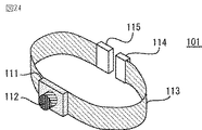
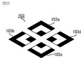
上記各実施の形態においては撮像機器15を固定して備える例を示したが、これに限られることはなく、本実施の形態6においては、撮像機器を可搬型とする場合について説明する。図23はこの発明の実施の形態6における作業確認システムの構成を示す図、図24は図23に示した作業確認システムの撮像機器の構成を示す図、図25は図23に示した作業確認システムの位置基準マークを示した図である。図において、上記各実施の形態と同様の部分は同一符号を付して説明を省略する。このように可搬型の撮像機器を使用する場合には、図23に示すように、作業対象物12または作業対象物12を位置決めする治具に、位置基準マーク103を設置して、撮像機器101にてこの位置基準マーク103を撮影することにより撮影位置を確定するものである。
Embodiment 6 FIG.
In each of the above embodiments, an example in which the
可搬型の撮像機器101としては、作業者13が装着可能なヘッドマウント型の撮像機器101が考えられる。撮像機器101は、カメラ本体111、カメラレンズ112、ベルト113、バックル114、115とにて構成され、作業者13の額や作業帽などに装着することができる。そして、位置基準マーク103は、例えば図23および図25に示すように、作業対象物12の四隅に表示することが考えられる。尚、図25は、図23において四隅に表示した位置基準マーク103a、103b、103c、103dの拡大した図を示すものである。
As the
次に上記のように構成された実施の形態6における作業確認システムの動作について説明する。画像処理部34の以下に示す動作以外は、上記各実施の形態と同様であるためその説明を適宜省略する。画像処理部34は、画像信号に写る各位置基準マーク103a、103b、103c、103dを検出して、推定位置および推定方向の推定値を、各位置基準マーク103a、103b、103c、103dと、グローブ11との位置関係から求めることができる。
Next, the operation of the work confirmation system according to the sixth embodiment configured as described above will be described. Since the operations other than those described below of the
上記のように構成された実施の形態6の作業確認システムによれば、上記各実施の形態と同様の効果を奏するのはもちろんこと、撮像機器が可搬型であるため、固定した撮像機器では障害物などで作業位置が隠れてしまうような状況であっても、撮影位置と方向を変えて画像信号を得ることができる。特にヘッドマウント型の撮像機器であれば、作業者から見た作業状況に近い画像信号が得られるため、障害物などで作業位置が隠れることが少ないと考えられる。 According to the work confirmation system of the sixth embodiment configured as described above, the same effects as those of the above-described embodiments can be obtained, and the imaging device is portable. Even in a situation where the work position is hidden by an object or the like, an image signal can be obtained by changing the shooting position and direction. In particular, in the case of a head-mounted imaging device, an image signal close to the work situation seen by the operator can be obtained, so that it is considered that the work position is less likely to be hidden by an obstacle or the like.
実施の形態7.
上記各実施の形態においては撮像機器を1台の例を示したが、これに限られることはなく、複数台の撮像機器を用いて、各撮像機器が作業状況を撮影できるように配置することも可能である。図26はこの発明の実施の形態7における作業確認システムの構成を示す図である。図において、上記各実施の形態と同様の部分は同一符号を付して説明を省略する。撮像機器15は、第一撮像機器15aと第二撮像機器15bとの複数台から構成される。
In each of the above-described embodiments, an example of one imaging device has been shown. However, the present invention is not limited to this, and a plurality of imaging devices are used so that each imaging device can capture a work situation. Is also possible. FIG. 26 is a diagram showing a configuration of a work confirmation system according to
上記のように構成された実施の形態7の作業確認システムによれば、上記各実施の形態と同様の効果を奏するのはもちろんこと、一方向からの撮像では死角となる部分において作業位置(グローブのマークの位置、マークの示す方向)を検出することができる。この場合、作業判定は、最も位置検出に望ましい撮像機器の画像を用いるよう、予め選択しておき、作業判定データを作成しておけばよい。 According to the work confirmation system of the seventh embodiment configured as described above, the same effects as those of the above-described embodiments can be obtained. In addition, the work position (globe The position of the mark, the direction indicated by the mark) can be detected. In this case, the work determination may be made in advance so as to use the image of the imaging device that is most desirable for position detection, and work determination data may be created.
尚、本発明は、その発明の範囲内において、各実施の形態を自由に組み合わせたり、各実施の形態を適宜、変形、省略することが可能である。 It should be noted that the present invention can be freely combined with each other within the scope of the invention, and each embodiment can be appropriately modified or omitted.
2 マーク、3 右手、11 グローブ、12 作業対象物、13 作業者、
14 作業机、15 撮像機器、15a 第一撮像装置、15b 第二撮像装置、
16 支持台、17 表示器、18 制御機器、19 画像信号入力線、
20 表示信号出力線、21 マーク、22 マーク、23 親指、24 人差し指、
25 中指、26 薬指、31 作業定義部、32 作業指示部、33 画像入力部、
34 画像処理部、35 作業確認部、36 結果記録部、41 設定画面、
42 作業指示画面、43 作業結果画面、50 マーク、51 マーク、
52 マーク、53 マーク、54 マーク、55 マーク、56 マーク、
57 マーク、58 マーク、59 マーク、60 マーク、61 マーク、
70 画像データ、71 コネクタ、72 コネクタ受け側、73 基板、
74 検出範囲、81 線分、82 線分、83 線分、84 線分、85 有向線分、86 中点、87 有向線分、88 中点、91 作業名、92 作業指示図、
93 作業指示メッセージ、94 組立台数の目標/実績、95 画像信号、
96 作業確認状態表示、97 作業対象変更ボタン、98 作業中断ボタン、
100 個人差補正用マーク、101 撮像機器、102 無線通信経路、
103 位置基準マーク、111 カメラ本体、112 カメラレンズ、
113 ベルト、114 バックル、115 バックル、121 位置基準マーク、
122 位置基準マーク、123 位置基準マーク、124 位置基準マーク、
131 撮像機器、132 撮像機器、201 基準有向線分、202 中点、
203 基準有向線分、204 中点、205 判定条件、206 判定条件、
207 基準有向線分、208 基準有向線分、209 判定条件、210 判定条件。
2 mark, 3 right hand, 11 glove, 12 work object, 13 worker,
14 working desks, 15 imaging devices, 15a first imaging device, 15b second imaging device,
16 Support base, 17 Display, 18 Control device, 19 Image signal input line,
20 display signal output line, 21 mark, 22 mark, 23 thumb, 24 index finger,
25 middle finger, 26 ring finger, 31 work definition part, 32 work instruction part, 33 image input part,
34 image processing unit, 35 work confirmation unit, 36 result recording unit, 41 setting screen,
42 work instruction screen, 43 work result screen, 50 mark, 51 mark,
52 mark, 53 mark, 54 mark, 55 mark, 56 mark,
57 mark, 58 mark, 59 mark, 60 mark, 61 mark,
70 image data, 71 connector, 72 connector receiving side, 73 substrate,
74 detection range, 81 line segment, 82 line segment, 83 line segment, 84 line segment, 85 directed line segment, 86 midpoint, 87 directed line segment, 88 midpoint, 91 work name, 92 work instruction diagram,
93 Work instruction message, 94 Assembly target / result, 95 Image signal,
96 Work confirmation status display, 97 Work object change button, 98 Work interrupt button,
100 personal difference correction mark, 101 imaging device, 102 wireless communication path,
103 position reference mark, 111 camera body, 112 camera lens,
113 belt, 114 buckle, 115 buckle, 121 position reference mark,
122 position reference mark, 123 position reference mark, 124 position reference mark,
131 imaging device, 132 imaging device, 201 reference directed line segment, 202 midpoint,
203 reference directed line segment, 204 midpoint, 205 judgment condition, 206 judgment condition,
207 Reference directed line segment, 208 Reference directed line segment, 209 determination condition, 210 determination condition.
Claims (11)
前記作業者が手に装着し、前記手の甲から指先にかけての方向性があるマークを有するグローブと、
前記グローブの前記マークを撮影する撮像機器と、
前記撮像機器にて撮影した前記マークの画像データと前記作業内容とを比較して合否判定を行う制御機器とを備えた作業確認システム。 In the work confirmation system that confirms the work content performed by the worker,
A glove having a mark attached to the hand by the operator and having directionality from the back of the hand to a fingertip;
An imaging device for photographing the mark of the globe;
A work confirmation system comprising: a control device that performs pass / fail judgment by comparing image data of the mark photographed by the imaging device and the work content.
前記作業内容を判定するための前記作業内容の作業位置および作業方向の判定条件データが格納されている作業定義部と、
前記画像データから前記マークの推定位置および推定方向を検出する画像処理部と、
前記推定位置および前記推定方向と、前記作業定義部の前記判定条件データとを比較して前記作業内容の前記合否判定を行う作業確認部とを備えた請求項1または請求項2に記載の作業確認システム。 The control device is
A work definition unit in which judgment position data for the work position and work direction of the work content for judging the work content is stored;
An image processing unit for detecting an estimated position and an estimated direction of the mark from the image data;
The work according to claim 1, further comprising: a work confirmation unit that compares the estimated position and the estimated direction with the determination condition data of the work definition unit to perform the pass / fail determination of the work content. Confirmation system.
前記結果記録部に蓄積された前記推定位置の標準偏差と前記推定方向の標準偏差とを分析する作業分析部とを備えた請求項3に記載の作業確認システム。 A result recording unit that accumulates work result data including the estimated position and the estimated direction detected by the image processing unit, and the pass / fail determination of the work confirmation unit;
The work confirmation system according to claim 3, further comprising a work analysis unit that analyzes a standard deviation of the estimated position and a standard deviation of the estimated direction accumulated in the result recording unit.
前記画像処理部は、前記画像データから前記マークの推定時間を検出し、
前記作業確認部は、前記推定時間を加えて、前記作業定義部の前記判定条件データとを比較して前記作業内容の前記合否判定を行う請求項3に記載の作業確認システム。 The work definition unit has a time of the work content in the determination condition data,
The image processing unit detects an estimated time of the mark from the image data;
The work confirmation system according to claim 3, wherein the work confirmation unit performs the pass / fail judgment of the work content by adding the estimated time and comparing the determination condition data of the work definition unit.
前記結果記録部に蓄積された前記推定位置の標準偏差、前記推定方向の標準偏差、および、前記推定時間の標準偏差を分析する作業分析部とを備えた請求項5に記載の作業確認システム。 A result recording unit that accumulates work result data including the estimated position, the estimated direction, and the estimated time detected by the image processing unit, and the pass / fail determination of the work confirmation unit;
The work confirmation system according to claim 5, further comprising: a work analysis unit that analyzes a standard deviation of the estimated position, a standard deviation of the estimated direction, and a standard deviation of the estimated time accumulated in the result recording unit.
前記作業確認部は、前記推定位置および前記推定方向を、前記基準値および前記個人差補正値を使用して修正して前記合否判定を行う請求項3から請求項7のいずれか1項に記載の作業確認システム。 The work definition unit has a reference value of the work position of the work content and an individual difference correction value of the work position of the worker,
The said operation confirmation part corrects the said estimated position and the said estimated direction using the said reference value and the said individual difference correction value, and performs the said pass / fail determination. Work confirmation system.
前記画像処理部は、前記補正用画像データから前記個人差補正値を求めて前記作業定義部に格納する請求項8に記載の作業確認システム。 The imaging device acquires correction image data obtained by photographing the mark in a state where the operator holds the individual difference correction mark,
The work confirmation system according to claim 8, wherein the image processing unit obtains the individual difference correction value from the correction image data and stores it in the work definition unit.
Priority Applications (1)
| Application Number | Priority Date | Filing Date | Title |
|---|---|---|---|
| JP2013253772A JP6016760B2 (en) | 2013-12-09 | 2013-12-09 | Work confirmation system |
Applications Claiming Priority (1)
| Application Number | Priority Date | Filing Date | Title |
|---|---|---|---|
| JP2013253772A JP6016760B2 (en) | 2013-12-09 | 2013-12-09 | Work confirmation system |
Publications (2)
| Publication Number | Publication Date |
|---|---|
| JP2015114676A true JP2015114676A (en) | 2015-06-22 |
| JP6016760B2 JP6016760B2 (en) | 2016-10-26 |
Family
ID=53528474
Family Applications (1)
| Application Number | Title | Priority Date | Filing Date |
|---|---|---|---|
| JP2013253772A Expired - Fee Related JP6016760B2 (en) | 2013-12-09 | 2013-12-09 | Work confirmation system |
Country Status (1)
| Country | Link |
|---|---|
| JP (1) | JP6016760B2 (en) |
Cited By (7)
| Publication number | Priority date | Publication date | Assignee | Title |
|---|---|---|---|---|
| JP2017045402A (en) * | 2015-08-28 | 2017-03-02 | 京セラドキュメントソリューションズ株式会社 | Work recording device |
| JPWO2016185634A1 (en) * | 2015-05-21 | 2017-08-31 | 株式会社ソニー・インタラクティブエンタテインメント | Information processing device |
| WO2017159562A1 (en) * | 2016-03-14 | 2017-09-21 | オムロン株式会社 | Action information generation device |
| WO2019021592A1 (en) * | 2017-07-24 | 2019-01-31 | 株式会社日立製作所 | Task refinement assistance system and method |
| CN110873551A (en) * | 2018-09-03 | 2020-03-10 | Juki株式会社 | Inspection apparatus |
| JP2021082204A (en) * | 2019-11-22 | 2021-05-27 | オムロン株式会社 | Work instruction system and work instruction method |
| WO2025115325A1 (en) * | 2023-11-28 | 2025-06-05 | 三菱重工業株式会社 | Work recording system and work recording method |
Citations (4)
| Publication number | Priority date | Publication date | Assignee | Title |
|---|---|---|---|---|
| JP2007156838A (en) * | 2005-12-05 | 2007-06-21 | Fujifilm Corp | Assembly work confirmation system and assembly work confirmation method |
| JP2009015809A (en) * | 2007-06-07 | 2009-01-22 | Ricoh Co Ltd | Motion analysis device |
| JP2013190941A (en) * | 2012-03-13 | 2013-09-26 | Nikon Corp | Information input output device, and head-mounted display device |
| JP2013218535A (en) * | 2012-04-09 | 2013-10-24 | Crescent Inc | Method and device for displaying finger integrated into cg image in three-dimensionally modeled cg image and wide viewing angle head mount display device for displaying three-dimensionally modeled cg image |
-
2013
- 2013-12-09 JP JP2013253772A patent/JP6016760B2/en not_active Expired - Fee Related
Patent Citations (4)
| Publication number | Priority date | Publication date | Assignee | Title |
|---|---|---|---|---|
| JP2007156838A (en) * | 2005-12-05 | 2007-06-21 | Fujifilm Corp | Assembly work confirmation system and assembly work confirmation method |
| JP2009015809A (en) * | 2007-06-07 | 2009-01-22 | Ricoh Co Ltd | Motion analysis device |
| JP2013190941A (en) * | 2012-03-13 | 2013-09-26 | Nikon Corp | Information input output device, and head-mounted display device |
| JP2013218535A (en) * | 2012-04-09 | 2013-10-24 | Crescent Inc | Method and device for displaying finger integrated into cg image in three-dimensionally modeled cg image and wide viewing angle head mount display device for displaying three-dimensionally modeled cg image |
Cited By (15)
| Publication number | Priority date | Publication date | Assignee | Title |
|---|---|---|---|---|
| JPWO2016185634A1 (en) * | 2015-05-21 | 2017-08-31 | 株式会社ソニー・インタラクティブエンタテインメント | Information processing device |
| JP2017045402A (en) * | 2015-08-28 | 2017-03-02 | 京セラドキュメントソリューションズ株式会社 | Work recording device |
| WO2017159562A1 (en) * | 2016-03-14 | 2017-09-21 | オムロン株式会社 | Action information generation device |
| JPWO2017159562A1 (en) * | 2016-03-14 | 2019-01-17 | オムロン株式会社 | Operation information generator |
| CN110945444A (en) * | 2017-07-24 | 2020-03-31 | 株式会社日立制作所 | Operation improvement support system and method |
| WO2019021592A1 (en) * | 2017-07-24 | 2019-01-31 | 株式会社日立製作所 | Task refinement assistance system and method |
| CN110873551A (en) * | 2018-09-03 | 2020-03-10 | Juki株式会社 | Inspection apparatus |
| JP2021082204A (en) * | 2019-11-22 | 2021-05-27 | オムロン株式会社 | Work instruction system and work instruction method |
| WO2021100388A1 (en) * | 2019-11-22 | 2021-05-27 | オムロン株式会社 | Work instruction system and work instruction method |
| KR20220054666A (en) * | 2019-11-22 | 2022-05-03 | 오므론 가부시키가이샤 | Work order system and work order method |
| CN114503040A (en) * | 2019-11-22 | 2022-05-13 | 欧姆龙株式会社 | Work instruction system and work instruction method |
| JP7395988B2 (en) | 2019-11-22 | 2023-12-12 | オムロン株式会社 | Work instruction system and work instruction method |
| KR102871787B1 (en) | 2019-11-22 | 2025-10-15 | 오므론 가부시키가이샤 | Work instruction system and work instruction method |
| US12694351B2 (en) | 2019-11-22 | 2026-07-28 | Omron Corporation | Work instruction system and work instruction method |
| WO2025115325A1 (en) * | 2023-11-28 | 2025-06-05 | 三菱重工業株式会社 | Work recording system and work recording method |
Also Published As
| Publication number | Publication date |
|---|---|
| JP6016760B2 (en) | 2016-10-26 |
Similar Documents
| Publication | Publication Date | Title |
|---|---|---|
| JP6016760B2 (en) | Work confirmation system | |
| JP5214511B2 (en) | Work process management system | |
| CN104023906B (en) | Operation management device and operation management system | |
| US10433119B2 (en) | Position determination device, position determining method, and storage medium | |
| CN106444852B (en) | Image processing apparatus, method for correcting position and commercial plant | |
| CN109963451A (en) | A kind of positioning method of printed circuit board components | |
| WO2014045508A1 (en) | Inspection device, inspection method, and inspection program | |
| CN108701346B (en) | Wiring inspection work support system | |
| WO2016174942A1 (en) | Information processing device, information processing method, and program | |
| JP2009289046A (en) | Operation support device and method using three-dimensional data | |
| CN109963455A (en) | A positioning system for printed circuit board components | |
| KR101802918B1 (en) | Apparatus for Scanning 3D Images and Operating Method thereof | |
| US20140191959A1 (en) | Pointing system and display having improved operable range | |
| CN109765990B (en) | Picture display control method and picture display control system | |
| JP2016099633A (en) | Maintenance inspection system using a portable terminal | |
| CN107535090B (en) | Device for generating component orientation determination data and method for generating component orientation determination data | |
| TW201523365A (en) | Auto calibration system and auto calibration method | |
| JP7213734B2 (en) | Information processing device and program | |
| JP6441763B2 (en) | Display device, display control method, and program therefor | |
| JP6342832B2 (en) | Input device | |
| TWI520100B (en) | Free space orientation and position determining method and system | |
| KR20080024252A (en) | Mouse interface device using camera, system and method by the device, and computer readable recording medium for realizing this | |
| CN104375626B (en) | Show processing method, the device and system of sign | |
| JP2016148622A (en) | Information processing apparatus, information processing method, and program | |
| CN109584226B (en) | Quality inspection system and method |
Legal Events
| Date | Code | Title | Description |
|---|---|---|---|
| A621 | Written request for application examination |
Free format text: JAPANESE INTERMEDIATE CODE: A621 Effective date: 20150929 |
|
| A131 | Notification of reasons for refusal |
Free format text: JAPANESE INTERMEDIATE CODE: A131 Effective date: 20160607 |
|
| A521 | Request for written amendment filed |
Free format text: JAPANESE INTERMEDIATE CODE: A523 Effective date: 20160720 |
|
| TRDD | Decision of grant or rejection written | ||
| A01 | Written decision to grant a patent or to grant a registration (utility model) |
Free format text: JAPANESE INTERMEDIATE CODE: A01 Effective date: 20160830 |
|
| A61 | First payment of annual fees (during grant procedure) |
Free format text: JAPANESE INTERMEDIATE CODE: A61 Effective date: 20160927 |
|
| R150 | Certificate of patent or registration of utility model |
Ref document number: 6016760 Country of ref document: JP Free format text: JAPANESE INTERMEDIATE CODE: R150 |
|
| R250 | Receipt of annual fees |
Free format text: JAPANESE INTERMEDIATE CODE: R250 |
|
| R250 | Receipt of annual fees |
Free format text: JAPANESE INTERMEDIATE CODE: R250 |
|
| R250 | Receipt of annual fees |
Free format text: JAPANESE INTERMEDIATE CODE: R250 |
|
| R250 | Receipt of annual fees |
Free format text: JAPANESE INTERMEDIATE CODE: R250 |
|
| R250 | Receipt of annual fees |
Free format text: JAPANESE INTERMEDIATE CODE: R250 |
|
| R250 | Receipt of annual fees |
Free format text: JAPANESE INTERMEDIATE CODE: R250 |
|
| LAPS | Cancellation because of no payment of annual fees |