JP2015114665A - Display apparatus - Google Patents
Display apparatus Download PDFInfo
- Publication number
- JP2015114665A JP2015114665A JP2014237897A JP2014237897A JP2015114665A JP 2015114665 A JP2015114665 A JP 2015114665A JP 2014237897 A JP2014237897 A JP 2014237897A JP 2014237897 A JP2014237897 A JP 2014237897A JP 2015114665 A JP2015114665 A JP 2015114665A
- Authority
- JP
- Japan
- Prior art keywords
- top cover
- display device
- cover
- light source
- bottom cover
- Prior art date
- Legal status (The legal status is an assumption and is not a legal conclusion. Google has not performed a legal analysis and makes no representation as to the accuracy of the status listed.)
- Pending
Links
Images

Classifications
-
- G—PHYSICS
- G02—OPTICS
- G02B—OPTICAL ELEMENTS, SYSTEMS OR APPARATUS
- G02B6/00—Light guides; Structural details of arrangements comprising light guides and other optical elements, e.g. couplings
- G02B6/0001—Light guides; Structural details of arrangements comprising light guides and other optical elements, e.g. couplings specially adapted for lighting devices or systems
- G02B6/0011—Light guides; Structural details of arrangements comprising light guides and other optical elements, e.g. couplings specially adapted for lighting devices or systems the light guides being planar or of plate-like form
- G02B6/0081—Mechanical or electrical aspects of the light guide and light source in the lighting device peculiar to the adaptation to planar light guides, e.g. concerning packaging
- G02B6/0085—Means for removing heat created by the light source from the package
-
- G—PHYSICS
- G09—EDUCATION; CRYPTOGRAPHY; DISPLAY; ADVERTISING; SEALS
- G09F—DISPLAYING; ADVERTISING; SIGNS; LABELS OR NAME-PLATES; SEALS
- G09F9/00—Indicating arrangements for variable information in which the information is built-up on a support by selection or combination of individual elements
-
- G—PHYSICS
- G02—OPTICS
- G02B—OPTICAL ELEMENTS, SYSTEMS OR APPARATUS
- G02B6/00—Light guides; Structural details of arrangements comprising light guides and other optical elements, e.g. couplings
- G02B6/0001—Light guides; Structural details of arrangements comprising light guides and other optical elements, e.g. couplings specially adapted for lighting devices or systems
- G02B6/0011—Light guides; Structural details of arrangements comprising light guides and other optical elements, e.g. couplings specially adapted for lighting devices or systems the light guides being planar or of plate-like form
- G02B6/0081—Mechanical or electrical aspects of the light guide and light source in the lighting device peculiar to the adaptation to planar light guides, e.g. concerning packaging
-
- G—PHYSICS
- G02—OPTICS
- G02F—OPTICAL DEVICES OR ARRANGEMENTS FOR THE CONTROL OF LIGHT BY MODIFICATION OF THE OPTICAL PROPERTIES OF THE MEDIA OF THE ELEMENTS INVOLVED THEREIN; NON-LINEAR OPTICS; FREQUENCY-CHANGING OF LIGHT; OPTICAL LOGIC ELEMENTS; OPTICAL ANALOGUE/DIGITAL CONVERTERS
- G02F1/00—Devices or arrangements for the control of the intensity, colour, phase, polarisation or direction of light arriving from an independent light source, e.g. switching, gating or modulating; Non-linear optics
- G02F1/01—Devices or arrangements for the control of the intensity, colour, phase, polarisation or direction of light arriving from an independent light source, e.g. switching, gating or modulating; Non-linear optics for the control of the intensity, phase, polarisation or colour
- G02F1/13—Devices or arrangements for the control of the intensity, colour, phase, polarisation or direction of light arriving from an independent light source, e.g. switching, gating or modulating; Non-linear optics for the control of the intensity, phase, polarisation or colour based on liquid crystals, e.g. single liquid crystal display cells
- G02F1/133—Constructional arrangements; Operation of liquid crystal cells; Circuit arrangements
- G02F1/1333—Constructional arrangements; Manufacturing methods
- G02F1/133308—Support structures for LCD panels, e.g. frames or bezels
-
- G—PHYSICS
- G02—OPTICS
- G02B—OPTICAL ELEMENTS, SYSTEMS OR APPARATUS
- G02B6/00—Light guides; Structural details of arrangements comprising light guides and other optical elements, e.g. couplings
- G02B6/0001—Light guides; Structural details of arrangements comprising light guides and other optical elements, e.g. couplings specially adapted for lighting devices or systems
- G02B6/0011—Light guides; Structural details of arrangements comprising light guides and other optical elements, e.g. couplings specially adapted for lighting devices or systems the light guides being planar or of plate-like form
- G02B6/0081—Mechanical or electrical aspects of the light guide and light source in the lighting device peculiar to the adaptation to planar light guides, e.g. concerning packaging
- G02B6/0086—Positioning aspects
- G02B6/009—Positioning aspects of the light source in the package
-
- G—PHYSICS
- G02—OPTICS
- G02F—OPTICAL DEVICES OR ARRANGEMENTS FOR THE CONTROL OF LIGHT BY MODIFICATION OF THE OPTICAL PROPERTIES OF THE MEDIA OF THE ELEMENTS INVOLVED THEREIN; NON-LINEAR OPTICS; FREQUENCY-CHANGING OF LIGHT; OPTICAL LOGIC ELEMENTS; OPTICAL ANALOGUE/DIGITAL CONVERTERS
- G02F1/00—Devices or arrangements for the control of the intensity, colour, phase, polarisation or direction of light arriving from an independent light source, e.g. switching, gating or modulating; Non-linear optics
- G02F1/01—Devices or arrangements for the control of the intensity, colour, phase, polarisation or direction of light arriving from an independent light source, e.g. switching, gating or modulating; Non-linear optics for the control of the intensity, phase, polarisation or colour
- G02F1/13—Devices or arrangements for the control of the intensity, colour, phase, polarisation or direction of light arriving from an independent light source, e.g. switching, gating or modulating; Non-linear optics for the control of the intensity, phase, polarisation or colour based on liquid crystals, e.g. single liquid crystal display cells
- G02F1/133—Constructional arrangements; Operation of liquid crystal cells; Circuit arrangements
- G02F1/1333—Constructional arrangements; Manufacturing methods
- G02F1/133308—Support structures for LCD panels, e.g. frames or bezels
- G02F1/133317—Intermediate frames, e.g. between backlight housing and front frame
Landscapes
- Physics & Mathematics (AREA)
- General Physics & Mathematics (AREA)
- Optics & Photonics (AREA)
- Nonlinear Science (AREA)
- Mathematical Physics (AREA)
- Chemical & Material Sciences (AREA)
- Crystallography & Structural Chemistry (AREA)
- Liquid Crystal (AREA)
- Theoretical Computer Science (AREA)
- Engineering & Computer Science (AREA)
- Planar Illumination Modules (AREA)
- Fastening Of Light Sources Or Lamp Holders (AREA)
- Arrangement Of Elements, Cooling, Sealing, Or The Like Of Lighting Devices (AREA)
- Led Device Packages (AREA)
- Devices For Indicating Variable Information By Combining Individual Elements (AREA)
Abstract
【課題】光源ユニットの放熱効果が増加した表示装置を提供する。
【解決手段】本発明による表示装置は、映像を表示する表示パネル、バックライトユニット、及びトップカバーを含む。バックライトユニットは、底面である第1ボトムカバー及び第1ボトムカバーから延在された第2ボトムカバーを含むボトムカバーを含む。トップカバーは、第1トップカバー及び第2トップカバーを含む。第1トップカバーは、表示パネルの上面の周辺部をカバーする。第2トップカバーは、第1トップカバーに接続されて第1トップカバーの延長方向に傾いた方向に延長される。平面上でバックライトユニットのエッジは、第1トップカバーのエッジよりさらに外側に突出する。第2ボトムカバーは、第2トップカバーと平行な方向に延長される表示装置。
【選択図】図2Provided is a display device in which the heat dissipation effect of a light source unit is increased.
A display device according to the present invention includes a display panel for displaying an image, a backlight unit, and a top cover. The backlight unit includes a bottom cover including a first bottom cover that is a bottom surface and a second bottom cover that extends from the first bottom cover. The top cover includes a first top cover and a second top cover. The first top cover covers the periphery of the upper surface of the display panel. The second top cover is connected to the first top cover and extended in a direction inclined in the extension direction of the first top cover. On the plane, the edge of the backlight unit protrudes further outward than the edge of the first top cover. The second bottom cover is a display device that extends in a direction parallel to the second top cover.
[Selection] Figure 2
Description
本発明は表示装置に関し、さらに詳細には表示品質が向上された表示装置に関する。 The present invention relates to a display device, and more particularly to a display device with improved display quality.
液晶表示装置、電気泳動表示装置、及びエレクトロ・ウェッティング表示装置のような非発光型表示装置は光を照射するための別のバックライトユニット(Backlight Unit)が必要である。 Non-light emitting display devices such as liquid crystal display devices, electrophoretic display devices, and electrowetting display devices require a separate backlight unit for irradiating light.
表示装置は映像を表示する表示パネル、バックライトユニット、及びトップカバーを含む。トップカバーは表示パネル及びバックライトユニットのエッジをカバーし、表示パネル及びバックライトユニットを結合する。 The display device includes a display panel for displaying an image, a backlight unit, and a top cover. The top cover covers the edges of the display panel and the backlight unit, and joins the display panel and the backlight unit.
バックライトユニットは映像が表示される表示面に対する光源の位置にしたがってエッジ型(edge type)と直下形(direct type)とに区分される。 The backlight unit is classified into an edge type and a direct type according to the position of a light source with respect to a display surface on which an image is displayed.
比較的高価な表示装置の場合、トップカバーの幅を減らして表示装置の側面ベゼルを最小化しようとする研究が進行されて来た。一方、トップカバーの幅が減ると、光源ユニットと導光板との間の距離を確保しにくい問題があり、(エッジ型バックライトユニット)導光板が熱膨張すると、表示パネル方向に膨脹して表示パネルを圧迫するようになる。結果的に表示装置の表示品質が低下する問題がある。また、トップカバーの幅が減ると、光源ユニットから発生する熱を放熱するための放熱機構の体積が小さくなってバックライトユニットが劣化する問題がある。 In the case of relatively expensive display devices, research has been undertaken to reduce the width of the top cover and minimize the side bezel of the display device. On the other hand, when the width of the top cover is reduced, there is a problem that it is difficult to secure a distance between the light source unit and the light guide plate. (Edge type backlight unit) When the light guide plate is thermally expanded, the display panel is expanded and displayed. It comes to squeeze the panel. As a result, there is a problem that the display quality of the display device deteriorates. Further, when the width of the top cover is reduced, there is a problem in that the backlight unit deteriorates because the volume of the heat dissipation mechanism for radiating heat generated from the light source unit is reduced.
比較的低価な表示装置の場合、表示装置の側面ベゼルを最少化しながら、表示品質を向上させることができる構造が必要である。 In the case of a relatively inexpensive display device, a structure capable of improving display quality while minimizing the side bezel of the display device is required.
本発明が達成しようとする課題は光源ユニットの放熱効果が増加した表示装置を提供することである。 An object of the present invention is to provide a display device in which the heat dissipation effect of the light source unit is increased.
本発明が達成しようする他の課題は導光板のエッジで光漏れを防止できる表示装置を提供することである。
本発明が達成しようとするその他の課題は導光板が表示パネルと垂直方向に熱膨張する問題を事前に防止できる表示装置を提供することである。
Another object to be achieved by the present invention is to provide a display device capable of preventing light leakage at the edge of the light guide plate.
Another problem to be achieved by the present invention is to provide a display device capable of preventing in advance the problem that the light guide plate is thermally expanded in the direction perpendicular to the display panel.
本発明の一実施形態に係る表示装置は、映像を表示する表示パネル、バックライトユニット、及びトップカバーを含む。 A display device according to an embodiment of the present invention includes a display panel that displays an image, a backlight unit, and a top cover.
前記バックライトユニットは、前記表示パネルに光を供給する。前記バックライトユニットは、第1ボトムカバー及び第2ボトムカバーを含む。前記第1ボトムカバーは、底面であり得る。前記第2ボトムカバーは、前記第1ボトムカバーから延在され得る。 The backlight unit supplies light to the display panel. The backlight unit includes a first bottom cover and a second bottom cover. The first bottom cover may be a bottom surface. The second bottom cover may extend from the first bottom cover.
前記トップカバーは、第1トップカバー及び第2トップカバーを包含することができる。前記第1トップカバーは、前記表示パネルの上面の周辺部をカバーすることができる。前記第2トップカバーは、前記第1トップカバーに接続されて前記表示パネルの側面及び前記バックライトユニットの側面をカバーし、前記第1トップカバーの延長方向に傾いた方向に延在され得る。 The top cover may include a first top cover and a second top cover. The first top cover may cover a peripheral portion of the upper surface of the display panel. The second top cover may be connected to the first top cover to cover a side surface of the display panel and a side surface of the backlight unit, and may extend in a direction inclined with respect to an extending direction of the first top cover.
平面上で前記バックライトユニットのエッジは、前記第1トップカバーのエッジよりさらに外側に突出し得る。前記第2ボトムカバーは、前記第2トップカバーと平行な方向に延長され得る。 The edge of the backlight unit may protrude further outward than the edge of the first top cover on a plane. The second bottom cover may be extended in a direction parallel to the second top cover.
前記第1トップカバーと前記第2トップカバーとが形成する角は、鈍角である。 The angle formed by the first top cover and the second top cover is an obtuse angle.
前記第2トップカバーと前記表示パネルの厚さ方向とが形成する角は、鋭角であり得る。 An angle formed by the second top cover and the thickness direction of the display panel may be an acute angle.
前記第1ボトムカバーと前記第2ボトムカバーとが形成する角は、前記鋭角であり得る。 An angle formed by the first bottom cover and the second bottom cover may be the acute angle.
前記バックライトユニットは、光源ユニット、導光板、反射板、光学シート、及び固定バーをさらに包含することができる。前記光学ユニットは、光を出光する光源及び前記光源を駆動する光源PCBを包含することができる。前記導光板は、前記光源から入光された光をガイドして上部に出射することができる。前記反射板は、前記導光板の下部に配置されて入光された光を反射することができる。前記光学シートは、前記導光板上に配置されて前記導光板で出射された光の効率を増加させ得る。前記固定バーは、前記光源ユニットを固定し、前記光源ユニットで発生した熱を放出することができる。 The backlight unit may further include a light source unit, a light guide plate, a reflection plate, an optical sheet, and a fixing bar. The optical unit may include a light source that emits light and a light source PCB that drives the light source. The light guide plate can guide light emitted from the light source and emit the light upward. The reflector may be disposed under the light guide plate and reflect incident light. The optical sheet may be disposed on the light guide plate to increase the efficiency of light emitted from the light guide plate. The fixing bar can fix the light source unit and release heat generated by the light source unit.
前記固定バーは、固定底部及び固定側壁部を包含することができる。前記固定底部は、前記第1ボトムカバー上に配置され得る。前記固定側壁部は、前記固定底部から延長されて内面に前記光源ユニットが接続され得る。 The fixing bar may include a fixed bottom portion and a fixed side wall portion. The fixed bottom portion may be disposed on the first bottom cover. The fixed side wall portion may extend from the fixed bottom portion, and the light source unit may be connected to an inner surface.
前記固定側壁部は、前記第1ボトムカバーと前記第2ボトムカバーとの間の空間に対応される形状を有し得る。前記固定側壁部は、前記固定底部に近くなるほど、増加する厚さを有し得る。 The fixed side wall portion may have a shape corresponding to a space between the first bottom cover and the second bottom cover. The fixed side wall portion may have a thickness that increases as it approaches the fixed bottom portion.
前記表示装置は、前記トップカバー及び前記ボトムカバーの間に配置されて前記トップカバー及び前記ボトムカバーと結合されるモールドフレームをさらに包含することができる。 The display device may further include a mold frame disposed between the top cover and the bottom cover and coupled to the top cover and the bottom cover.
前記モールドフレームは、第1モールドフレーム及び第2モールドフレームを包含することができる。前記第1モールドフレームは、前記第1トップカバーと平行な方向に延長されて前記表示パネルを支持することができる。前記第2モールドフレームは、前記第2トップカバーと平行な方向に延長され得る。 The mold frame may include a first mold frame and a second mold frame. The first mold frame may be extended in a direction parallel to the first top cover to support the display panel. The second mold frame may be extended in a direction parallel to the second top cover.
前記第2モールドフレームと前記表示パネルの厚さ方向とが形成する角は、鋭角であり得る。 An angle formed by the second mold frame and the thickness direction of the display panel may be an acute angle.
本発明の一実施形態に係る表示装置は、映像を表示する表示パネル、バックライトユニット、及びトップカバーを含む。 A display device according to an embodiment of the present invention includes a display panel that displays an image, a backlight unit, and a top cover.
前記バックライトユニットは、前記表示パネルに光を提供する。前記バックライトユニットは、第1ボトムカバー及び第2ボトムカバーを含む。前記第1ボトムカバーは、底面であり得る。前記第2ボトムカバーは、前記第1ボトムカバーから延在され得る。 The backlight unit provides light to the display panel. The backlight unit includes a first bottom cover and a second bottom cover. The first bottom cover may be a bottom surface. The second bottom cover may extend from the first bottom cover.
前記トップカバーは、第1トップカバー、第2トップカバー、及び第3トップカバーを包含することができる。前記第1トップカバーは、前記表示パネルの上面の周辺部をカバーすることができる。前記第2トップカバーは、前記第1トップカバーに接続されて前記表示パネルの側面一部及び前記バックライトユニットの側面一部をカバーすることができる。前記第3トップカバーは、前記第2トップカバーに接続されて前記表示パネルの側面の残りの部分及び前記バックライトユニットの側面残りの部分をカバーし、前記第1トップカバーの延長方向に傾いた方向に延長され得る。 The top cover may include a first top cover, a second top cover, and a third top cover. The first top cover may cover a peripheral portion of the upper surface of the display panel. The second top cover may be connected to the first top cover to cover a part of the side surface of the display panel and a part of the side surface of the backlight unit. The third top cover is connected to the second top cover to cover the remaining side portion of the display panel and the remaining side surface of the backlight unit, and is inclined in the extending direction of the first top cover. Can be extended in the direction.
平面上で前記バックライトユニットのエッジは前記第1トップカバーのエッジよりさらに外側に突出し得る。前記第2ボトムカバーは、前記第3トップカバーと平行な方向に延長され得る。 The edge of the backlight unit may protrude further outward than the edge of the first top cover on a plane. The second bottom cover may be extended in a direction parallel to the third top cover.
前記第1トップカバーと前記第2トップカバーとが形成する角は、直角であり得る。 An angle formed by the first top cover and the second top cover may be a right angle.
前記第3トップカバーと前記表示パネルの厚さ方向とが形成する角は、鋭角であり得る。 An angle formed by the third top cover and the thickness direction of the display panel may be an acute angle.
本発明による表示装置によれば、光源ユニットの放熱効果を増加させることができる。 According to the display device of the present invention, the heat dissipation effect of the light source unit can be increased.
また、表示装置は導光板のエッジで光漏れを防止することができる。 In addition, the display device can prevent light leakage at the edge of the light guide plate.
また、表示装置は導光板が表示パネルと垂直方向に熱膨張する問題を事前に防止することができる。 In addition, the display device can prevent in advance a problem that the light guide plate is thermally expanded in a direction perpendicular to the display panel.
以上の本発明の目的、他の目的、特徴及び長所は添付された図面に関連する以下の望ましい実施形態を通じて容易に理解できる。しかし、本発明はここで説明される実施形態に限定されなく、他の形態に具体化されることもあり得る。むしろ、紹介される実施形態は開示された内容が徹底であり、完全になることできるように、そして当業者に本発明の思想が十分に伝達され得るようにするために提供される。 The above and other objects, features, and advantages of the present invention can be easily understood through the following preferred embodiments with reference to the accompanying drawings. However, the present invention is not limited to the embodiments described herein, and may be embodied in other forms. Rather, the embodiments presented are provided so that the content disclosed will be thorough and complete, and will fully convey the spirit of the invention to those skilled in the art.
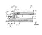
図1は本発明の一実施形態に係る表示装置1000を示した分解斜視図であり、図2は図1の表示装置の一部断面図である。
FIG. 1 is an exploded perspective view showing a
図1及び図2を参照すれば、表示装置1000は表示パネル100、バックライトユニット200、トップカバー300、及びモールドフレーム400を含む。
Referring to FIGS. 1 and 2, the
表示パネル100はバックライトユニット200から光を受けて映像を表示する。表示パネル100は液晶表示パネルのような非発光型表示パネルであり、以下、表示パネル100は液晶表示パネルであることを一例として説明する。
The
表示パネル100は下部基板110、下部基板110に対向する上部基板120、及び2つの基板との間に配置された液晶層を含む。下部基板110は複数のゲートライン及び複数のデータライン、ゲートライン及びデータラインに対応する複数の画素を含む。画素の各々には薄膜トランジスタが具備される。上部基板120はカラーフィルター及びブラックマトリックスを包含することができる。カラーフィルターは画素の各々に対応するように配置される。ブラックマトリックスはカラーフィルターのエッジに具備されてゲートライン、データライン、及び薄膜トランジスタと対応するように配置される。
The
表示パネル100が長方形状である時、表示パネル100の一面の第1辺の延長方向を第1方向DR1であると定義し、第1辺に隣接する第2辺の延長方向を第2方向DR2であると定義し、表示パネル100の厚さ方向を第3方向DR3であると定義する。図1で第1辺が長辺であり、第2辺が短辺であることを一例として図示したが、これに制限されることではなく、第1辺が短辺であり、第2辺が長辺であり得る。
When the
表示装置1000は印刷回路基板110及びフレキシブル印刷回路基板120をさらに包含することができる。印刷回路基板110には表示パネル100を駆動するための駆動部が実装され得る。駆動部は各種駆動信号を生成し、駆動信号はフレキシブル印刷回路基板120を通じて表示パネル100に伝達することができる。フレキシブル印刷回路基板120は表示パネル100及び印刷回路基板110を電気的に接続させる。フレキシブル印刷回路基板120はTCP(tape carrier package)又はCOF(chip on film)であり得る。
The
また、表示装置1000は表示パネル100を介して配置された一対の偏光板(図示せず)をさらに包含することができる。偏光板(図示せず)は互いに直交する光の透過軸を有し得る。
Further, the
バックライトユニット200は光源ユニット210、導光板220、反射板230、光学シート240、固定バー250、及びボトムカバー260を含む。
The
光源ユニット210は光源211及び光源PCB212を含む。光源211は少なくとも1つ以上実装され、光源PCB212に実装されて光源PCB212から電源が供給されて発光する。光源211は発光ダイオード(Light Emitting Diode:LED)であり得る。光源PCB212は光源211を駆動するための電源を外部から供給されて光源211に伝達する。
The
本実施形態では光源211は発光ダイオードであることを一例として説明したが、光源211は冷陰極蛍光ランプ(Cold Cathode Fluorescent Lamp:CCFL)又は平板蛍光ランプ(Flat Fluorescent Lamp:FFL)であり得る。
In the present embodiment, the
図1及び図2で光源ユニット210は1つであることを一例として図示したが、これに制限されることではなく、光源ユニット210は2つ以上であり得る。また、図1及び図2で光源ユニット210はエッジ型構造として導光板220の側面に対応するように具備されたことと図示したが、これに制限されることではない。
Although FIG. 1 and FIG. 2 illustrate one
導光板220は光源211から入射した光を誘導して導光板220の上部に出射する役割を果たす。
The
導光板220は入射面221と出射面222とを有する板状である。図1で導光板220は平面上で四角形であることを一例として示した。入射面221には光源211で発生した光が入射し、入射した光は出射面222を通過して導光板220の上部に出射される。
The
反射板230は導光板220の下部に配置される。反射板230は光源211で発生した光の中で導光板220に到達せず、漏れた光を反射する。
The
光学シート240は導光板220上に配置されて導光板220から出射される光の効率を増加させる。
The
光学シート240は拡散シート241、集光シート242、及び保護シート243を順次的に包含することができる。拡散シート241は入射した光を拡散させる役割を果たす。集光シート242は拡散シート241で拡散された光を集めて輝度を高くする役割を果たす。保護シート243は集光シート242を保護し、視野角を確保する役割を果たす。図1及び図2で光学シート240は3枚で構成されたことを一例として図示したが、場合によって4枚以上に構成され得る。
The
固定バー250は光源ユニット210を固定し、光源ユニット210で発生した熱を放出する。
The fixing
固定バー250は固定底部251及び固定側壁部252を包含することができる。固定底部251は導光板220の下部に配置され、導光板220の平面上の形状に対応する形状を有し得る。固定側壁部252は固定底部251から延在される。固定側壁部252の内面には光源ユニット210が接続され得る。固定バー250はアルミニウム又はアルミニウム合金のような熱伝導性が優れた金属から製造され、圧出、板金、鋳造等の多様な加工方法により形成され得る。固定バー250の具体的な形状に対しては後述される。
The fixing
ボトムカバー260は内部に収納空間が設けられ、収納空間に光源ユニット210、導光板220、反射板230、光学シート240、及び固定バー250を収納する。
The
ボトムカバー260は第1ボトムカバー261及び第2ボトムカバー262を含む。第1ボトムカバー261は底面に配置される。第2ボトムカバー262は第1ボトムカバー261から延在される。ボトムカバー260の具体的な形状に対しては後述される。
The
トップカバー300は表示パネル100の上面一部を覆い、モールドフレーム400及びボトムカバー260に結合される。
The
トップカバー300は第1トップカバー310及び第2トップカバー320を包含することができる。第1トップカバー310は表示パネル100の上面の周辺部をカバーする。第1トップカバー310は開口部を具備する環形状であり得る。第2トップカバー320は第1トップカバー310から延在される。第2トップカバー320は表示パネル100の側面及びバックライトユニット200の側面をカバーする。
The
第1トップカバー310は表示パネル100の上面と平行な方向に延長され得る。第2トップカバー320は第1トップカバー310の延長方向に傾いた方向に延長され得る。
The first
第1方向DR1及び第2方向DR2がなす平面に対して第1トップカバー310及び第2トップカバー320が形成する角は鈍角である。言い換えれば、第2トップカバー320と第3方向DR3とが形成する角は鋭角(θ)であり得る。
The angle formed by the first
モールドフレーム400はトップカバー300及びボトムカバー260の間に配置されてトップカバー300及びボトムカバー260と結合され得る。モールドフレーム400は第1モールドフレーム410及び第2モールドフレーム420を包含することができる。
The
第1モールドフレーム410は表示パネル100を支持する。第1モールドフレーム410は開口部を具備する環形状に提供され得る。第1モールドフレーム410とボトムカバー260との間には光源ユニット210、導光板220、反射板230、光学シート240、及び固定バー250が配置され得る。
The
第2モールドフレーム420は第1モールドフレーム410に接続される。第2モールドフレーム420は第2トップカバー310及び第2ボトムカバー262の間に配置されて第2トップカバー310及び第2ボトムカバー262に接続され得る。
The
第1モールドフレーム410は第1トップカバー310と平行な方向に延長され得る。第2モールドフレーム420は第2トップカバー320と平行な方向に延長され得る。第1方向DR1及び第2方向DR2がなす平面に対して第1モールドフレーム410及び第2モールドフレーム420が形成する角は鈍角である。言い換えれば、第2モールドフレーム420と第3方向DR3とが形成する角は鋭角(θ)であり得る。
The
モールドフレーム400は第3モールドフレーム430をさらに包含することができる。第3モールドフレーム430は第1トップカバー310を支持するために第1モールドフレーム410から第3方向DR3へ突出された形状を有し得る。
The
第1ボトムカバー261は第1トップカバー310と平行な方向に延長され得る。第2ボトムカバー262は第2トップカバー320と平行な方向に延長され得る。第1方向DR1及び第2方向DR2がなす平面に対して第1ボトムカバー261及び第2ボトムカバー262が形成する角は鋭角(θ)であり得る。
The
固定側壁部252は第1ボトムカバー261及び第2ボトムカバー262の間の第3方向DR3空間に対応する形状を有し得る。したがって、固定側壁部252は固定底部251に近くなるほど、増加する厚さを有し得る。
The fixed
表示装置1000は接続部材SCをさらに包含することができる。接続部材SCは第2トップカバー320、第2モールドフレーム420、及び第2ボトムカバー262を貫通して接続することができる。接続部材SCはスクリュー、ボルト、及びボスの中でいずれか1つであり得る。接続部材SCは第2トップカバー320、第2モールドフレーム420、及び第2ボトムカバー262の各々の延長方向に対して垂直になる方向に接続され得る。
The
本発明の一実施形態に係る表示装置によれば、第1方向DR1及び第2方向DR2がなす平面上でバックライトユニット200は第1トップカバー310よりさらに外側に突出され得る。
According to the display device according to the embodiment of the present disclosure, the
第2トップカバー320が第3方向DR3に対して鋭角(θ)ぐらい傾き、第2モールドフレーム420及び第2ボトムカバー262は第2トップカバー320と平行に配置され得る。したがって、第1方向DR1及び第2方向DR2がなす平面上で第1ボトムカバー261のエッジは第2トップカバー320に隣接する第1トップカバー310のエッジより延長領域EAぐらい外側に突出される。
The second
延長領域EAによって第1ボトムカバー261及び第2ボトムカバー262の間の空間が確保され、固定側壁部252の厚さが増加する形状を有し得る。第2ボトムカバー262が第1ボトムカバー261から垂直に延在される比較例と比較して、固定側壁部262の体積がさらに大きくなることができるので、光源ユニット210の放熱効果が増加することができる。
A space between the
また、延長領域EAによって導光板220が比較例に比べて第1方向DR1及び第2方向DR2にさらに大きく形成されることができるので、導光板220のエッジでの光漏れを防止することができる。
Further, since the
導光板220は加熱される場合、第1方向DR1及び第2方向DR2に膨張し、光源ユニット210等のような構成によって阻まれて、それ以上に第1方向DR1及び第2方向DR2に膨張しない場合、第3方向DR3に膨張し得る。導光板220が第3方向DR3に膨張すれば、表示パネル100に圧力が加わるようになり、これは表示装置の表示品質の低下として表れる。延長領域EAによって光源ユニット210と導光板220との間の距離が比較例に比べてさらに確保されることができるので、導光板220が第3方向DR3に膨脹する問題を事前に防止することができる。
When the
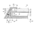
図3は本発明の一実施形態に係る表示装置1100を示した一部断面図である。
FIG. 3 is a partial cross-sectional view showing a
図3の表示装置1100は図1及び図2に示した表示装置1000と比較してセットフレーム500をさらに含む。以下ではセットフレーム500に対して具体的に説明し、残る構成に対する説明は図1及び図2を参照した説明にしたがう。
The
セットフレーム500はトップカバー300をカバーする。セットフレーム500は使用者に視認される最外側フレームとして表示パネル100、バックライトユニット200、トップカバー300、及びモールドフレーム400を保護することと共に表示装置の外的デザインを決定する。
The
セットフレーム500は第1セットフレーム510、第2セットフレーム520、及び第3セットフレーム530を含む。
The
第1セットフレーム510は第1トップカバー310上に配置されて第1トップカバー310をカバーする。第1セットフレーム510は第1トップカバー310と平行に延長される。
The
第2セットフレーム520は第1セットフレーム510の一端に接続され、第2トップカバー320上に配置されて第2トップカバー320をカバーする。第2セットフレーム520は第2トップカバー320と平行に延長される。
The
第3セットフレーム530は第1セットフレーム510の他端に接続され、表示パネル100上に配置されて第1トップカバー310の一側面311をカバーする。
The
セットフレーム500はトップカバー300と類似な形状を有するので、トップカバー300をカバーするための最適化された形状を有する。セットフレーム500がトップカバー300と互に異なる形状を有する比較例と比較して、セットフレーム500の形状によってトップカバー300がセットフレーム500に密着されて結合され、結果的にベゼルが減少され得る。
Since the
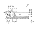
図4は本発明の一実施形態に係る表示装置1200を示した一部断面図である。
FIG. 4 is a partial cross-sectional view showing a
図4の表示装置1200は図3に示した表示装置1100と比較してセットフレーム600に差異があり、残りは実質的に類似である。以下ではセットフレーム600に対して具体的に説明し、残る構成に対する説明は図1、図2、及び図3を参照した説明にしたがう。
The
図4を参照すれば、セットフレーム600は第2トップカバー320上に配置されて第2トップカバー320をカバーする。セットフレーム600は第2トップカバー320と平行に延長される。
Referring to FIG. 4, the
図4の表示装置1200によると、図3の表示装置1100の効果を有することと共に図3の表示装置1100で第1セットフレーム510及び第3セットフレーム530を除去することができるので、表示装置1200の厚さを減少させ得る。
4 has the effects of the
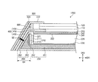
図5は本発明の一実施形態に係る表示装置1300を示した一部断面図である。
FIG. 5 is a partial cross-sectional view showing a
図5の表示装置1300は図1及び図2に示した表示装置1000と比較してトップカバー700に差異があり、残りは実質的に類似である。以下ではトップカバー700に対して具体的に説明し、残る構成に対する説明は図1及び図2を参照した説明にしたがう。
The
トップカバー700は表示パネル100の上面一部を覆い、モールドフレーム400及びボトムカバー260に結合される。
The
トップカバー700は第1トップカバー710、第2トップカバー720、及び第3トップカバー730を包含することができる。第1トップカバー710は表示パネル100の上面周辺部をカバーする。第1トップカバー710は開口部を具備する環形状に提供され得る。
The
第2トップカバー720は第1トップカバー710から延在される。第2トップカバー720は表示パネル100の側面一部及びバックライトユニット200の側面の一部をカバーする。
The second
第3トップカバー730は第2トップカバー720から延在される。第3トップカバー730は表示パネル100の側面の残りの部分及びバックライトユニット200の側面の残りの部分をカバーする。
The third
第1トップカバー710は表示パネル100の上面と平行な方向に延長され得る。第2トップカバー720は第1トップカバー710の延長方向と垂直になる方向に延長され得る。即ち、第1トップカバー710と第2トップカバー720とが形成する角は直角であり得る。第3トップカバー730は第1トップカバー710の延長方向に傾いた方向に延長され得る。
The first
第1方向DR1及び第2方向DR2がなす平面に対して第1トップカバー710及び第3トップカバー730が形成する角は鈍角である。言い換えれば、第3トップカバー730と第3方向DR3とが形成する角は鋭角(θ)であり得る。
The angle formed by the first
以上、添付された図面を参照して本発明の実施形態を説明したが、本発明が属する技術分野で通常の知識を有する者は本発明がその技術的な思想や必須的な特徴を変形せず、他の具体的な形態に実施できることを理解できる。したがって、以上で記述した実施形態にはすべての面で例示的なことであり、限定的なことではないこととして理解しなければならない。 The embodiments of the present invention have been described above with reference to the accompanying drawings, but those skilled in the art to which the present invention pertains may modify the technical idea and essential features of the present invention. However, it can be understood that the present invention can be implemented in other specific forms. Accordingly, it should be understood that the embodiments described above are illustrative in all aspects and not limiting.
1000・・・表示装置
100・・・表示パネル
200・・・バックライトユニット
210・・・光源ユニット
220・・・導光板
230・・・反射板
240・・・光学シート
300、700・・・トップカバー
400・・・モールドフレーム
500、600・・・セットフレーム
1000 ...
Claims (10)
底面である第1ボトムカバー及び前記第1ボトムカバーから延在された第2ボトムカバーを含むボトムカバーを含み、前記表示パネルに光を供給するバックライトユニットと、
前記表示パネルの上面の周辺部をカバーする第1トップカバー及び前記第1トップカバーに延在して前記表示パネルの側面及び前記バックライトユニットの側面をカバーし、前記第1トップカバーの延長方向に傾いた方向に延長される第2トップカバーを含むトップカバーと、を含み、
平面上で前記バックライトユニットのエッジは、前記第1トップカバーのエッジよりさらに外側に突出し、前記第2ボトムカバーは、前記第2トップカバーと平行な方向に延長される表示装置。 A display panel for displaying images,
A backlight unit that includes a bottom cover including a first bottom cover that is a bottom surface and a second bottom cover that extends from the first bottom cover, and supplies light to the display panel;
A first top cover that covers a peripheral portion of an upper surface of the display panel, and extends to the first top cover to cover a side surface of the display panel and a side surface of the backlight unit, and an extension direction of the first top cover A top cover including a second top cover extended in a direction inclined to
A display device in which an edge of the backlight unit protrudes further outward than an edge of the first top cover on a plane, and the second bottom cover extends in a direction parallel to the second top cover.
光を生成する光源及び前記光源を駆動する光源PCBを含む光源ユニットと、
前記光源から入射した光をガイドして上部に出射する導光板と、
前記導光板の下部に配置されて入射した光を反射する反射板と、
前記導光板上に配置されて前記導光板から出射した光の効率を増加させる光学シートと、
前記光源ユニットを固定し、前記光源ユニットで発生した熱を放出する固定バーと、をさらに含むことを特徴とする請求項1に記載の表示装置。 The backlight unit is
A light source unit including a light source that generates light and a light source PCB that drives the light source;
A light guide plate that guides the light incident from the light source and emits it to the top;
A reflective plate that is disposed under the light guide plate and reflects incident light;
An optical sheet disposed on the light guide plate to increase the efficiency of light emitted from the light guide plate;
The display device according to claim 1, further comprising: a fixing bar that fixes the light source unit and releases heat generated in the light source unit.
前記第1ボトムカバー上に配置された固定底部と、
前記固定底部から延在して内面に前記光源ユニットが接続される固定側壁部と、を含むことを特徴とする請求項5に記載の表示装置。 The fixing bar is
A fixed bottom portion disposed on the first bottom cover;
The display device according to claim 5, further comprising: a fixed side wall portion extending from the fixed bottom portion and connected to the inner surface of the light source unit.
前記第1トップカバーと平行な方向に延長されて前記表示パネルを支持する第1モールドフレームと、
前記第2トップカバーと平行な方向に延長される第2モールドフレームと、を含むことを特徴とする請求項9に記載の表示装置。 The mold frame is
A first mold frame extending in a direction parallel to the first top cover and supporting the display panel;
The display device according to claim 9, further comprising: a second mold frame extending in a direction parallel to the second top cover.
Applications Claiming Priority (2)
| Application Number | Priority Date | Filing Date | Title |
|---|---|---|---|
| KR10-2013-0151696 | 2013-12-06 | ||
| KR1020130151696A KR20150066312A (en) | 2013-12-06 | 2013-12-06 | Display apparatus |
Publications (1)
| Publication Number | Publication Date |
|---|---|
| JP2015114665A true JP2015114665A (en) | 2015-06-22 |
Family
ID=53270976
Family Applications (1)
| Application Number | Title | Priority Date | Filing Date |
|---|---|---|---|
| JP2014237897A Pending JP2015114665A (en) | 2013-12-06 | 2014-11-25 | Display apparatus |
Country Status (4)
| Country | Link |
|---|---|
| US (1) | US9507079B2 (en) |
| JP (1) | JP2015114665A (en) |
| KR (1) | KR20150066312A (en) |
| CN (1) | CN104700719A (en) |
Families Citing this family (12)
| Publication number | Priority date | Publication date | Assignee | Title |
|---|---|---|---|---|
| KR102423634B1 (en) * | 2015-10-28 | 2022-07-22 | 삼성디스플레이 주식회사 | Backlight unit display apparatus including the same, and did display device including a plurality of the display apparatue |
| KR20170067203A (en) * | 2015-12-07 | 2017-06-16 | 삼성디스플레이 주식회사 | Light guide unit and display apparatus |
| CN105551389A (en) * | 2016-03-07 | 2016-05-04 | 京东方科技集团股份有限公司 | Display panel and display device |
| CN205535626U (en) * | 2016-04-11 | 2016-08-31 | 合肥鑫晟光电科技有限公司 | Frame, backlight unit structure and display device glue |
| KR102490166B1 (en) * | 2016-05-26 | 2023-01-20 | 엘지디스플레이 주식회사 | Display device |
| KR102566815B1 (en) * | 2016-08-31 | 2023-08-14 | 엘지디스플레이 주식회사 | display device |
| JP6878225B2 (en) * | 2017-09-15 | 2021-05-26 | デクセリアルズ株式会社 | Manufacturing method of transparent panel, manufacturing method of optical device |
| KR102413716B1 (en) * | 2017-09-25 | 2022-06-28 | 삼성디스플레이 주식회사 | Display panel |
| CN208889233U (en) * | 2018-11-06 | 2019-05-21 | 京东方科技集团股份有限公司 | Framework and electronics picture frame |
| KR102652550B1 (en) * | 2019-02-13 | 2024-03-29 | 삼성디스플레이 주식회사 | Curved display device |
| CN210514867U (en) * | 2019-11-12 | 2020-05-12 | 北京京东方显示技术有限公司 | A plastic frame, a backlight module and a liquid crystal display device |
| WO2021230395A1 (en) * | 2020-05-13 | 2021-11-18 | 엘지전자 주식회사 | Display device |
Family Cites Families (27)
| Publication number | Priority date | Publication date | Assignee | Title |
|---|---|---|---|---|
| JPH05142535A (en) * | 1991-08-29 | 1993-06-11 | Meitaku Syst:Kk | Incident light supply device for edge light panel |
| JP2991052B2 (en) | 1994-09-16 | 1999-12-20 | 松下電器産業株式会社 | Liquid crystal display |
| JPH095744A (en) | 1995-04-20 | 1997-01-10 | Toshiba Corp | Flat panel display |
| JP2002031791A (en) | 2000-07-14 | 2002-01-31 | Toshiba Corp | Liquid crystal display |
| JP3529347B2 (en) * | 2000-10-25 | 2004-05-24 | Nec液晶テクノロジー株式会社 | Circuit board protection structure, method for manufacturing the same, and liquid crystal display device |
| JP2004253187A (en) | 2003-02-18 | 2004-09-09 | Toshiba Matsushita Display Technology Co Ltd | Illumination unit and liquid crystal display device using the same |
| KR20050077751A (en) | 2004-01-29 | 2005-08-03 | 아사히 가라스 가부시키가이샤 | Container for flat panel display, and flat panel display using the same |
| KR101084858B1 (en) | 2004-06-18 | 2011-11-21 | 엘지디스플레이 주식회사 | Module of LCD |
| KR100640889B1 (en) | 2004-08-20 | 2006-11-02 | 엘지전자 주식회사 | LCD module of LCD |
| KR20060129787A (en) * | 2005-06-13 | 2006-12-18 | 삼성전자주식회사 | LCD Display |
| KR100694516B1 (en) | 2005-06-16 | 2007-03-13 | 하이쎌(주) | Backlighting module |
| KR100727166B1 (en) | 2005-08-29 | 2007-06-13 | 엘지전자 주식회사 | LCD module fixing structure |
| CN101004515A (en) * | 2006-01-21 | 2007-07-25 | 鸿富锦精密工业(深圳)有限公司 | Full run-down type backlight module |
| KR100822052B1 (en) | 2006-10-18 | 2008-04-15 | 주식회사 씨엔에스 | LCD module with LED display unit and backlight unit |
| JP2008170691A (en) | 2007-01-11 | 2008-07-24 | Toshiba Matsushita Display Technology Co Ltd | Liquid crystal display device |
| JP5010527B2 (en) * | 2007-06-04 | 2012-08-29 | 住友化学株式会社 | Light guide plate unit, surface light source device, and liquid crystal display device |
| KR101418932B1 (en) * | 2007-12-10 | 2014-07-14 | 삼성디스플레이 주식회사 | Display device, upper storage container, and display device assembly method |
| JP5104426B2 (en) | 2008-03-13 | 2012-12-19 | パナソニック株式会社 | Image display device |
| CN101349778A (en) * | 2008-09-10 | 2009-01-21 | 友达光电(苏州)有限公司 | Light guide plate and backlight module |
| KR101507739B1 (en) * | 2008-12-26 | 2015-04-08 | 삼성디스플레이 주식회사 | Liquid crystal display and fabricating method of the same |
| KR101593418B1 (en) * | 2009-01-22 | 2016-02-15 | 삼성디스플레이 주식회사 | Display device |
| KR20120102174A (en) * | 2011-02-16 | 2012-09-18 | 삼성디스플레이 주식회사 | Backlight assembly, display apparatus having the same and method for assembling the display apparatus |
| JP2013025330A (en) | 2011-07-14 | 2013-02-04 | Canon Inc | Operation display device |
| KR101948168B1 (en) | 2011-12-08 | 2019-04-26 | 엘지디스플레이 주식회사 | Narrow bezel type liquid crystal display device |
| US20130234921A1 (en) * | 2012-03-06 | 2013-09-12 | Guofu Tang | Reflection-Light Backlight Module and LCD Device |
| CN102606952B (en) * | 2012-03-06 | 2014-10-15 | 深圳市华星光电技术有限公司 | Reflective incidence backlight module and liquid crystal display device |
| KR101433571B1 (en) * | 2013-01-24 | 2014-08-27 | 엘지디스플레이 주식회사 | Liquid crystal display device |
-
2013
- 2013-12-06 KR KR1020130151696A patent/KR20150066312A/en not_active Withdrawn
-
2014
- 2014-05-23 US US14/285,737 patent/US9507079B2/en active Active
- 2014-11-04 CN CN201410612436.6A patent/CN104700719A/en active Pending
- 2014-11-25 JP JP2014237897A patent/JP2015114665A/en active Pending
Also Published As
| Publication number | Publication date |
|---|---|
| KR20150066312A (en) | 2015-06-16 |
| US20150160405A1 (en) | 2015-06-11 |
| CN104700719A (en) | 2015-06-10 |
| US9507079B2 (en) | 2016-11-29 |
Similar Documents
| Publication | Publication Date | Title |
|---|---|---|
| JP2015114665A (en) | Display apparatus | |
| JP5844107B2 (en) | Display device having backlight assembly | |
| US8192055B2 (en) | Backlight device and display device using the same | |
| KR100687926B1 (en) | LCD Display | |
| US20070247564A1 (en) | Blacklight unit having a heat receiving member | |
| JP2008304630A (en) | Liquid crystal display | |
| KR20120019140A (en) | Liquid crystal display device | |
| CN106019667A (en) | Display device | |
| JP2010177076A (en) | Tandem surface light source device, and liquid crystal display device using the same | |
| JP4890485B2 (en) | Backlight unit and liquid crystal display device including the same | |
| WO2012169441A1 (en) | Lighting device, display device and television receiver | |
| JP2009205866A (en) | Illumination unit and liquid crystal display device | |
| US20130265520A1 (en) | Display device | |
| US7371002B2 (en) | Back light module and system for liquid crystal panels | |
| KR102322455B1 (en) | Display device | |
| JP2010122330A (en) | Liquid crystal display device | |
| WO2011052259A1 (en) | Lighting device, and display device | |
| JP5098778B2 (en) | LIGHTING DEVICE, LIQUID CRYSTAL DISPLAY DEVICE, AND ELECTRONIC DEVICE | |
| KR101807872B1 (en) | Backlight Unit and Liquid Crystal Display Device having the same | |
| KR100845895B1 (en) | LED backlight device | |
| US20120212974A1 (en) | Display module and display apparatus | |
| KR101238873B1 (en) | Heat condunction member and liquid crystal display having the same | |
| JP2008216406A5 (en) | ||
| KR100983503B1 (en) | Backlight assembly and liquid crystal display device having the same | |
| CN110770500A (en) | Lighting device and display device |