JP2015114653A - Image projection device - Google Patents
Image projection device Download PDFInfo
- Publication number
- JP2015114653A JP2015114653A JP2013259248A JP2013259248A JP2015114653A JP 2015114653 A JP2015114653 A JP 2015114653A JP 2013259248 A JP2013259248 A JP 2013259248A JP 2013259248 A JP2013259248 A JP 2013259248A JP 2015114653 A JP2015114653 A JP 2015114653A
- Authority
- JP
- Japan
- Prior art keywords
- smoke
- image projection
- light
- image
- main body
- Prior art date
- Legal status (The legal status is an assumption and is not a legal conclusion. Google has not performed a legal analysis and makes no representation as to the accuracy of the status listed.)
- Granted
Links
Images


Landscapes
- Projection Apparatus (AREA)
- Transforming Electric Information Into Light Information (AREA)
Abstract
【課題】装置周辺での発煙の有無を判定できる画像投影装置を提供する。【解決手段】スクリーン310に画像を投影するプロジェクタ1において、煙を検知する煙検知手段として、煙センサー61が接続された煙検知部151と、温度を検知する温度検知手段として、温度センサー62が接続された温度検知部152とを備えた。そして、煙検知部151及び温度検知部152の検知結果に基づいて、装置本体100周辺での外部要因による発煙生じているか否かを判定する判定手段として、本体制御部110で実行される判定プログラムも備えた。【選択図】図4An image projection apparatus capable of determining the presence or absence of smoke around the apparatus is provided. In a projector that projects an image on a screen, a smoke detection unit to which a smoke sensor is connected as smoke detection means for detecting smoke, and a temperature sensor as a temperature detection means for detecting temperature are provided. And a connected temperature detector 152. Based on the detection results of the smoke detection unit 151 and the temperature detection unit 152, a determination program executed by the main body control unit 110 as a determination unit that determines whether or not smoke is generated due to an external factor around the apparatus main body 100 Also provided. [Selection] Figure 4
Description
本発明は、スクリーン等の投影面に静止画や動画の画像を投影するプロジェクタ等の画像投影装置に関するものである。 The present invention relates to an image projection apparatus such as a projector that projects a still image or a moving image on a projection surface such as a screen.
画像投影装置は、多数の人が集まる催物や会議が開催される建物の部屋等に設置されて使用されることが多く、建物で火災が発生したときに火元の消火や避難を促す報知等に用いたいとの要請が従来からあった。
例えば、特許文献1には、火災等の災害発生時に、建物内の部屋(室内)に集まった多数の人の避難誘導を行う目的で、通信回線から受信した災害情報(災害発生情報)に基づいて、避難誘導用の画像を投影する画像投影装置が記載されている。
Image projection devices are often installed and used in buildings where a large number of people gather and events are held, and when a fire breaks out in a building, a notification that prompts the fire source to extinguish or evacuate. There has been a request for use in the past.
For example,
しかし、特許文献1の画像投影装置は、例え、装置周辺で、発煙が生じても、通信回線から災害情報を受信するまでは、避難誘導用の画像を投影する制御は開始されない。このため、避難誘導用の画像を投影する制御を開始するころには、装置周辺の発煙箇所からの炎が大きくなって被害が拡大するおそれがある。
上記のような理由から、通信回線を介することなく、装置周辺での発煙の有無を判定可能な画像投影装置が望まれる。
However, even if the image projection apparatus of
For the above reasons, an image projection apparatus that can determine the presence or absence of smoke around the apparatus without using a communication line is desired.
本発明は以上の問題点に鑑みなされたものであり、その目的は、装置周辺での発煙の有無を判定できる画像投影装置である。 The present invention has been made in view of the above problems, and an object thereof is an image projection apparatus capable of determining the presence or absence of smoke around the apparatus.
上記目的を達成するために、請求項1に記載の発明は、投影面に画像を投影する画像投影装置において、煙を検知する煙検知手段と、温度を検知する温度検知手段と、前記煙検知手段及び前記温度検知手段の検知結果に基づいて、装置周辺での発煙が生じているか否かを判定する判定手段と、を備えたことを特徴とするものである。 In order to achieve the above object, according to a first aspect of the present invention, there is provided an image projection apparatus for projecting an image on a projection surface, a smoke detection means for detecting smoke, a temperature detection means for detecting temperature, and the smoke detection. And determination means for determining whether or not smoke is generated around the apparatus based on the detection result of the temperature detection means.
本発明は、装置周辺での発煙の有無を判定できる画像投影装置を提供できる。 The present invention can provide an image projection device capable of determining the presence or absence of smoke around the device.
以下、本発明を画像投影装置であるプロジェクタ(以下、プロジェクタ1という)に適用した一実施形態について、複数の実施例、及び従来例を挙げて説明する。
本実施形態のプロジェクタ1は、パソコンやビデオカメラ等から入力される静止画や動画等の画像(映像)データを基に投影する画像を生成し、その画像を被投影対象であるスクリーン等に投影する画像投影装置である。
Hereinafter, an embodiment in which the present invention is applied to a projector (hereinafter referred to as a projector 1) that is an image projection apparatus will be described with reference to a plurality of examples and a conventional example.
The
画像投影装置として広く知られた液晶プロジェクタは、近来、画像生成部に有した液晶パネルの高解像化、光源の高効率化にともなう明るさの改善、低価格化などが進んでいる。
また、変調信号に応じて画像形成する空間光変調素子として、DMD(Digital Micro−mirror Device)素子を利用した小型軽量なものも普及し、オフィスや学校だけでなく、家庭でも画像投影装置が利用されようになってきている。
Liquid crystal projectors that are widely known as image projection apparatuses have recently been improved in the resolution and the cost reduction with the increase in resolution of the liquid crystal panel included in the image generation unit, the efficiency of the light source, and the like.
In addition, as a spatial light modulation element that forms an image in accordance with a modulation signal, a small and lightweight element using a DMD (Digital Micro-mirror Device) element is also widely used, and the image projection apparatus is used not only in offices and schools but also at home. It is becoming.
まず、本実施形態のプロジェクタ1の基本的な全体構成及び動作について、図を用いて説明する。
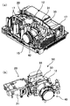
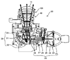
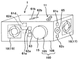
図1は、本実施形態に係る画像投影装置であるプロジェクタ1の外観説明図であり、図1(a)が斜め上方から見た外観斜視図、図1(b)が図1(a)に示すプロジェクタ1の投影状態を図中右側から見た右側面図である。図2は、外装カバーを外したプロジェクタ1の内部構成と配置を示す斜視説明図であり、図2(a)は外装カバーを外したプロジェクタ1の内部構成と配置を概要斜視図、図2(b)は図2(a)の太線枠で囲まれた部分の斜視図である。図3は、投影機構部50を構成する光源部20、画像生成部30、及び投射光学部40の横断面図である。
First, the basic overall configuration and operation of the
1A and 1B are external explanatory views of a
本実施形態のプロジェクタ1は、入力画像(映像)信号を変換した変調信号に応じて画像(映像)形成する空間光変調素子としてのDMD素子を画像生成部に設けたフロント投影タイプのプロジェクタである。
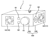
図1(a)、(b)に示すように、プロジェクタ1の装置本体100は、主に大部分の装置が内設される略立方体形状の筐体部106と、筐体部106から被投射対象であるスクリーン310側に突出する投射レンズ15を保持した円筒状の鏡胴部105とからなる。
また、図1(a)に示すように、プロジェクタ1(筐体部106)の正面には、装置電源を供給するためのACインレット13、パソコンやビデオカメラ等の外部機器と接続するための入出力端子14、投影画像の光を出射する投射レンズ15等が設けられている。
プロジェクタ1の上面(設置面の反対側)には、プロジェクタ1の操作者であるユーザがプロジェクタ1を操作するための操作ボタンやプロジェクタ1の動作状態を示すインジケーターを有した操作部11が設けられている。また、図1(b)に示すように、投射レンズ15の鏡胴部105の上部には、スクリーン310に映し出されている投影画像を拡大したり、縮小したりするズームレバー12が設けられている。
The
As shown in FIGS. 1 (a) and 1 (b), the apparatus
Further, as shown in FIG. 1A, an
On the upper surface of the projector 1 (on the opposite side of the installation surface), an
図1(a)、(b)に示すように床やテーブル等の上面等の設置面に対して上置きした場合の、プロジェクタ1における外装カバーの投影方向に向って左側面には、冷却用の外気を取り入れる(吸気する)吸気口16が設けられている。吸引された外気は、熱源の光源21や駆動基板(不図示)へ移動しながら光源21や駆動基板を冷却する。その後、排気ファン19により排気口18から排気される(図2参照)。
図2(a)、(b)、図3に示すように、画像投影手段である投影機構部50は、光源21の光をDMD素子33に導く光源部20と、光源部20の光源21からの光を用いて画像を生成する画像生成部30と、投影画像を投射する投射光学部40とを有している。
As shown in FIGS. 1 (a) and 1 (b), on the left side of the
As shown in FIGS. 2A, 2 </ b> B, and 3, the
光源部20は、光源21、ランプフード23、集光レンズ24、カラーホイール25、ホイール駆動モータ26、ライトトンネル27、2枚のリレーレンズ28を有している。
そして、図に示す高圧水銀ランプのランプやLED等の発光素子を用いた光源21からの白色光は、図3の矢印で示すように、回転する円盤状のカラーホイール25を通ることにより単位時間毎にR、G、Bの各色が繰り返す光に変換(分光)される。このカラーホイール25は、円盤形状のものであり、ホイール駆動モータ26のモータ軸に固定され、回転方向にR(レッド)、G(グリーン)、B(ブルー)などのフィルタが設けられている。カラーホイール25により分光された光は、ライトトンネル27へ入射する。
The
The white light from the
ライトトンネル27は、板ガラスを張り合わせて筒状に構成された四角筒形状であり、その内周面が鏡面となっている。そして、カラーホイール25からライトトンネル27に入射した光は、ライトトンネル27の内周の鏡面で複数回反射しながら均一な面光源にされて、2枚のレンズが組み合わされたリレーレンズ28へ向けて出射される。
そして、図3の矢印で示すように、2枚のリレーレンズ28を透過する際に光の軸上色収差が補正されつつ集光され、画像生成部30の平面ミラー31、凹面ミラー32により反射され、DMD素子33の画像生成面上に結像される。
The
As indicated by the arrows in FIG. 3, when passing through the two
ここで、画像生成部30のDMD素子33の画像生成面には、可動式の複数のマイクロミラーからなる略矩形のミラー面を有し、各マイクロミラーが時分割駆動されることで所定の画像を生成する。
具体的には、DMD素子33の画像生成面に対して平行に進む光源21からの光を、平面ミラー31、凹面ミラー32でDMD素子33の画像生成面に向けて折り返して、DMD素子33の画像生成面に照射する。DMD素子33の画像生成面には、可動式の複数のマイクロミラーが格子状に配列されており、DMD素子33の各マイクロミラーは、鏡面をねじれ軸周りに所定角度傾斜させることができ、「ON」と「OFF」の2つの状態を持たせることができる。
Here, the image generation surface of the
Specifically, the light from the
マイクロミラーが「ON」の時は、光源部20からの光を投射光学部40に向けて反射されて、複数のレンズを通り拡大された画像光は、図1(b)に示すように投射レンズ15からスクリーン310上へ拡大投影される。一方、マイクロミラーが「OFF」の時は、照明ブラケットなどの側面に保持されたOFF光板(不図示)に向けて光源21からの光を反射する。
したがって、各マイクロミラーを個別に駆動することにより、入力画像信号(データ)を変換した変調信号に応じて、画素ごとに光の投射を制御することができ、画像を生成することができる。なお、OFF光板(不図示)に向けて反射された光は、熱となって吸収され外側の空気の流れで冷却される。
When the micromirror is “ON”, the light from the
Therefore, by individually driving each micromirror, light projection can be controlled for each pixel in accordance with a modulation signal obtained by converting an input image signal (data), and an image can be generated. In addition, the light reflected toward the OFF light plate (not shown) is absorbed as heat and cooled by the flow of outside air.
画像生成部30のDMD素子33のマイクロミラーで反射された画像光を、投射レンズ15からスクリーン310上へ拡大投影(投射)する投射光学部40には、複数のレンズ群が金属、又は保持部材等で保持固定されている。また、投射光学部40には、スクリーン310に画像を投影する際の焦点距離を調整する焦点調整レンズ群と、上記したズームレバー12に連動して移動し、投影する際の画角を調整するズーム調整レンズ群とを有している。
In the projection
なお、本実施形態のプロジェクタ1では、スクリーン310までの距離を検知する距離センサー(不図示)を有し、この距離センサーで検知した距離、又は操作部11の焦点調整ボタン(不図示)を操作して焦点調整レンズ群を焦点モータで移動させて調整する。また、ズーム調整に関しては、ズームレバー12を摘んで回転させることで、ズーム調整レンズ群を移動させて調整するか、操作部11のズーム調整ボタン(不図示)を操作してズーム調整レンズ群をズームモータ(不図示)で移動させて調整する。
The
ここで、上記したように、画像投影装置は、多数の人が集まる催物や会議が開催される建物の部屋等に設置されて使用されることが多く、建物で火災が発生したときに火元の消火や避難を促す報知等に用いたいとの要請が従来からあった。
しかし、上記した特許文献1に記載の画像投影装置のように、通信回線から受信した災害情報に基づいて、避難誘導用の画像を投影する画像投影装置では、通信回線から災害情報を受信するまでは、避難誘導用の画像を投影する制御は開始されない。このため、避難誘導用の画像を投影する制御を開始するころには、炎が大きくなって、火災による被害が拡大するおそれがある。
Here, as described above, the image projection apparatus is often installed and used in a room of a building where a large number of people gather or an event is held. There has been a request to use it for fire-fighting and evacuation notifications.
However, in the image projection device that projects an image for evacuation guidance based on the disaster information received from the communication line, like the image projection device described in
そして、火災による被害の拡大を抑制するには、炎が大きくなる前の装置周辺での発煙が生じているか否かを判定することが有効である。これは、一般的に、装置周辺の発煙箇所で炎が大きくなる前は、発煙箇所で温度が異常上昇した空気が装置近傍に到達するよりも先に、発煙箇所の煙が装置近傍に到達するためである。
しかし、装置近傍に到達する煙は、装置周辺で発煙した煙だけでなく、次のように装置内や装置近傍での発煙による煙が到達する場合がある。
詳しくは後述するが、例えば、本実施例のプロジェクタ1では、プロジェクタ1(以下、位置を特定するときは装置本体100という)の吸気口16や排気口18が遮蔽物で塞がれたり、投影光の光路が装置本体100近傍の遮蔽物で塞がれたりする場合がある。このような状態が継続されると、装置本体100内の温度が異常上昇して、その構成部材が破損して発煙したり、遮蔽物が加熱されて発煙したりする場合がある。
In order to suppress the expansion of damage caused by fire, it is effective to determine whether or not smoke is generated around the device before the flame becomes large. In general, before the flame becomes large at the smoke generation area around the apparatus, the smoke at the smoke generation area reaches the vicinity of the apparatus before the air whose temperature has abnormally increased at the smoke generation area reaches the vicinity of the apparatus. Because.
However, the smoke reaching the vicinity of the apparatus is not limited to the smoke generated around the apparatus, but may be caused by the smoke generated in or near the apparatus as follows.
As will be described in detail later, for example, in the
上記のような理由から、炎が発火して大きくなる前の装置本体100周辺での外部要因による発煙の有無を適切に判定するためには、装置本体100や装置本体100近傍での内部要因による発煙と区別して判定する必要がある。
そこで、本実施形態では、炎が大きくなる前の装置本体100周辺での外部要因による発煙の有無を判定できるプロジェクタ1を提供することを目標とした。すなわち、炎が大きくなって、装置本体100や装置本体100近傍の温度が異常上昇する本格的な火災になる前の予兆としての装置本体100周辺での発煙の有無を判定できるプロジェクタ1を提供することを目標とした。
For the above reasons, in order to appropriately determine the presence or absence of smoke due to external factors around the device
Therefore, the present embodiment aims to provide a
また、装置本体100や装置本体100近傍での内部要因による発煙と区別して、炎が発火して大きくなる前の装置本体100周辺での外部要因による発煙の有無を適切に判定して、火災による被害の拡大を抑制できるプロジェクタ1を提供することを目標とした。
そして、判定結果に基づいて、装置本体100や装置本体100近傍での内部要因による発煙、又は装置本体100周辺での外部要因による発煙に、それぞれ応じた適切な処理が行えるプロジェクタ1を提供することを目標とした。
次に、本実施形態の画像投影装置であるプロジェクタ1に、本発明を適用した複数の実施例を説明する。
Further, it is distinguished from smoke generated by an internal factor in the apparatus
Then, based on the determination result, to provide a
Next, a plurality of examples in which the present invention is applied to the
(実施例1)
本実施形態のプロジェクタ1の実施例1について、図を用いて説明する。
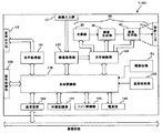
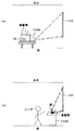
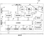
図4は、本実施例の制御関係のブロック図、図5は、火災が発生しするときの、装置本体100周辺での発煙、及び炎が大きくなった場合の説明図である。図6は、装置本体100や装置本体100近傍での発煙が生じた場合の説明図である。そして、図6(a)が本実施例のフロント投影タイプのプロジェクタ1の吸気口16が、バインダー等の遮蔽物により塞がれ、装置内温度が異常上昇した状態が継続し、内部の構成部材が故障して発煙が生じたときの説明図である。また、図6(b)が、例えば、斜め上方へ投影する投影タイプのプロジェクタ1で投影光の光路上をバインダー等の遮蔽物で塞いで、遮蔽物が加熱されて発煙が生じたときの説明図である。
(Example 1)
Example 1 of the
FIG. 4 is a block diagram of the control relationship of this embodiment, and FIG. 5 is an explanatory diagram when smoke is generated around the apparatus
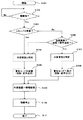
図7は、本実施例のプロジェクタ1の煙センサー61や温度センサー62等の配置説明図である。図8は、本実施例の外部要因(装置周辺)での発煙と、装置や内部要因(装置近傍)での発煙とを区別して判定し、それぞれ対応した処理を行う具体例1のフロー図である。図9は、本実施例の外部要因での発煙と、装置や内部要因での発煙とを区別して判定し、それぞれ対応した処理を行う具体例2のフロー図である。
FIG. 7 is an explanatory diagram of the arrangement of the
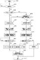
まず、本実施例のプロジェクタ1の各部の制御について、図4を用いて簡単に説明する。
図4に示すようにプロジェクタ1には、装置本体100内の各部の動作や設定を制御する本体制御部110を備えている。また、操作制御部120、画像処理部132、光学制御部133、音声処理部141、外部通信手段である送受信部143、外部記憶部144、ファン制御部145、及び電源部146を備えており、本体制御部110と制御信号等の通信を行っている。
加えて、本実施例のプロジェクタ1では、煙センサー61が接続され、その検出結果を信号に変換して本体制御部110に送信する煙検知部151を備えている。また、温度センサー62が接続され、その検出結果を信号に変換して本体制御部110に送信する温度検知部152を備えている。
First, control of each part of the
As shown in FIG. 4, the
In addition, the
本体制御部110は、中央演算処理装置(CPU)、及び読み込み及び書き換え可能なラム(RAM)や、主に読み込み専用のロム(ROM)等の高速な記憶装置等を有し、ロム内等に格納されたプログラムに基づいて、各部の制御や設定等を行う。なお、ラム及びロムの他に、これらと比べると低速だが、より容量が大きな不揮発性の記憶装置も有している。
操作制御部120は、操作部11から入力される指示を信号に変換して本体制御部110に送信するとともに、本体制御部110から各部の動作状態等を受信してインジケーターに示す。
画像処理部132は、画像入力部131から入力される画像信号を、本体制御部110の制御に基づいて、明暗やノイズ除去等の画像処理を施して、光学制御部133に処理後の画像信号を出力する。
The main
The
The
光学制御部133は、本体制御部110の制御に基づいて、投影機構部50を構成する光源部20、画像生成部30、及び投射光学部40を制御する。そして、画像処理部132から入力した画像信号や、本体制御部110のロム、不揮発性の記憶装置、及び外部記憶部144に記憶した画像データに基づいて、投影機構部50から投射面であるスクリーン310等に画像投影が行われることとなる。
音声処理部141は、本体制御部110の制御に基づいて、パソコン等の外部機器から入出力端子14を介して入力された音声信号を、音声出力手段であるスピーカー65(図7参照)や、装置外の音響システム等に、それぞれに応じた形式に変換して出力する。また、本体制御部110の制御に基づいて、本体制御部110のロム、不揮発性の記憶装置、及び外部記憶部144に記憶した音声データも出力する。
送受信部143は、プロジェクタ1を用いる部屋がある建物等に設置された通信回線である構内通信網(LAN)等との通信を行うための端子や回路により構成され、構内通信網を介して、他の機器と通信を行うことができる。
The
Based on the control of the main
The transmission /
外部記憶部144は、小型でデータの書き換えが可能なメモリーカードや、USBメモリ等を接続可能に設けられたものであり、本体制御部110のロムの書き換えや、不揮発性の記憶装置への画像データ等のデータの書き込むや書き出しに用いられるものである。
ファン制御部145は、後述する装置本体100内に設けられた温度センサー62や、本体制御部110から受信した各部の駆動状況に応じて、装置本体100内の空冷に用いられる吸気ファン17や排気ファン19の駆動を制御するものである。
電源部146は、本体制御部110の制御に基づいて、装置本体100内の各部に電力を供給するものである。なお、ACインレット13に、商用電源に電源コードが接続されて通電が開始されたら、少なくとも本体制御部110と、後述する煙センサー61及び温度センサー62を動作させるため、煙検知部151及び温度検知部152への電力の供給を開始する。
The
The
The power supply unit 146 supplies power to each unit in the apparatus
煙検知部151は、装置本体100内や装置本体100の筐体部106の側板や装置本体100内に設けられる煙センサー61が接続され、煙センサー61とで煙検知手段を構成している。
温度検知部152は、装置本体100内や装置本体100の筐体部106の側板に設けられる温度センサー62が接続され、温度センサー62とで温度検知手段を構成している。
そして、本実施例のプロジェクタ1は、火災の予兆検知を行なうために、通常、装置本体100内の温度の異常上昇を検知するために設けられることが多い温度検知手段を構成する温度検知部152に加え、煙検知手段を構成する煙検知部151を備えている。
また、これらの検知結果に基づいて、次の判定を行う判定手段として、本体制御部110で実行される判定プログラム(不図示)も備えている。
The
The
The
Further, a determination program (not shown) executed by the main
上記した判定プログラムでは、装置本体100周辺での外部要因による発煙が生じているか否か判定する。また、装置本体100や装置本体100近傍での内部要因による発煙が生じているか否かも判定する。そして、発煙が装置本体100周辺、又は装置本体100や装置本体100近傍のいずれで生じているかを区別して判定する。つまり、外部要因による発煙が生じているか、内部要因による発煙が生じているかも区別して判定する。
In the above determination program, it is determined whether or not smoke is generated due to an external factor around the apparatus
上記のように、判定することで、装置本体100周辺での発煙の有無を判定できるプロジェクタ1を提供できる。すなわち、炎が大きくなって、装置本体100や装置本体100近傍の温度が異常上昇するような本格的な火災になる前の予兆としての装置本体100周辺での発煙の有無を判定できるプロジェクタ1を提供できる。
また、装置本体100内や装置本体100近傍での内部要因による発煙である場合と、装置本体100周辺での外部要因による発煙である場合とで、それぞれ適したプロジェクタ1の制御、及び警告や情報の出力が行え、それぞれの被害の拡大を抑制できる。
As described above, it is possible to provide the
In addition, the
また、上記のように判定することで、内部要因又は外部要因による発煙にそれぞれ対応した処理を行うことが可能となり、内部要因によるプロジェクタ1の故障や発煙による不具合、及び火災による被害の拡大を抑制できるプロジェクタ1を提供できる。
具体的な処理としては、装置本体100の周辺で外部要因による発煙が生じていると判定した場合、火元の消火や避難を促す警告画像の画像投影や音声出力を行って所定時間だけ経過した後、稼動を停止するようにプロジェクタ1を制御する処理等が挙げられる。
一方、装置本体100や装置本体100近傍で内部要因による発煙が生じていると判定した場合、遮蔽物の除去を促す警告画像の画像投影や音声出力を行って所定時間だけ経過した後、稼動を停止するようにプロジェクタ1を制御する処理等が挙げられる。
加えて、通信回線である構内通信網(LAN)を介して、建物内の他の部屋等に配置された外部機器等に発煙が生じた原因や発生状況を早期に配信(通信)することができ、火災による被害の拡大の抑制効果を高めることも可能となる。
In addition, by determining as described above, it is possible to perform processing corresponding to smoke generation due to internal factors or external factors, and to suppress the failure of the
As specific processing, when it is determined that smoke due to an external factor has occurred around the apparatus
On the other hand, if it is determined that smoke is generated due to an internal factor in the apparatus
In addition, it is possible to quickly distribute (communicate) the cause and the state of occurrence of smoke in an external device or the like placed in another room in the building via a local area network (LAN) that is a communication line. It is also possible to increase the effect of suppressing the expansion of damage caused by fire.
ここで、火災の火元となり得る、装置本体100周辺での外部要因による発煙が生じた場合と、炎が大きくなった場合の具体的な例について、図5を用いて説明する。
例えば、図5に示すように、プロジェクタ1が天井から吊り下げた支持具にプロジェクタ1の底部を固定する天吊りの下置きで設置され、スクリーン310上に画像投影が可能なように配置されているものとする。
そして、プロジェクタ1に電力が通電され、プロジェクタ1が正常稼動時の装置本体100内や装置本体100近傍の温度(以下、通常の動作温度という)の範囲内で稼動している場合には、一般的に、炎の熱が伝達する前に火災の事前検知として先に煙を検知する。
このため、煙検知部151で煙を検知したときに、温度検知部152で検知した装置本体100内や装置本体100近傍の温度が、通常の動作温度の範囲を越えない場合、装置本体100周辺で外部要因による発煙が生じていると判定できる。これは、装置本体100周辺での外部要因による発煙が生じた場合、プロジェクタ1が画像投影を行っている状態、又はスタンバイの状態に関わらず、一般的に、炎で加熱された空気が装置本体100近傍に到達するよりも先に、煙が到達するためである。
Here, a specific example in the case where smoke is generated due to an external factor around the apparatus
For example, as shown in FIG. 5, the
When power is supplied to the
For this reason, when smoke is detected by the
次に、装置本体100内や装置本体100近傍で内部要因による発煙が生じた場合の具体的な例について、図6(a)、(b)を用いて説明する。
例えば、図6(a)に示すように、プロジェクタ1が床に配置されたテーブル上に上置きで、スクリーン310上に画像投影が可能なように配置されているものとする。
このよう設置されていると、プロジェクタ1の近くにいる操作者や観客が、吸気口16内の吸気ファン17の音がうるさかったり、所持した資料やバインダー等の置き場所がない場合に、吸気口16の近傍に所持したバインダー等をたけかけてしまう場合がある。すると、バインダー等が遮蔽物となって吸気口16を塞いでしまい、吸気口16から装置本体100内を空冷する空気が取り込めず、装置本体100内の温度が異常上昇して、装置本体100内の構成部材のいずれかが故障する等して発煙が生じる場合がある。
Next, a specific example in the case where smoke is generated due to an internal factor in the apparatus
For example, as shown in FIG. 6A, it is assumed that the
With such an installation, if the operator or spectator near the
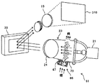
また、図6(b)に示すように、投射レンズ15が上向きの超短焦点縦置きプロジェクタ1が、スクリーン310上に画像投影が可能なように配置されているものとする。
このよう設置されていると、操作者が一旦、スクリーン310への投影光を遮るために、所持した資料やバインダー等の遮蔽物を投射レンズ15上へ置き、投影光を遮蔽したい場合がある。すると、投射レンズ15で集光した光である投影光によりバインダー等の遮蔽物が投影光で加熱されて投射レンズ15の周囲の温度が異常上昇したり、吸気口16から吸気する空気の温度が上昇することに起因して、装置本体100内の温度が異常上昇したりする。このような状態が継続すると、加熱されたバインダー等の遮蔽物から発煙が生じたり、装置本体100内の構成部材のいずれかが故障する等して発煙が生じたりする場合がある。
Further, as shown in FIG. 6B, it is assumed that the ultra-short focus
In such a case, there is a case where the operator once puts a shielding object such as a document or a binder on the
したがって、煙検知部151で煙を検知したときに、プロジェクタ1が稼動しており、装置本体100内や装置本体100近傍の温度が異常上昇している場合には、装置本体100や装置本体100近傍で内部要因による発煙が生じているものと判定できる。
なお、他の内部要因としては、プロジェクタ1の吸気ファン17や排気ファン19の故障や、環境温度の異常上昇等で装置本体100内の温度が異常上昇し、光源21として用いている高圧水銀ランプや基板上の電解コンデンサの破損等による発煙が考えられる。
Therefore, when the smoke is detected by the
Other internal factors include a high-pressure mercury lamp used as the
そこで、本実施例のプロジェクタ1では、煙検知部151に接続される煙センサー61や温度検知部152に接続される温度センサー62等を、図7の配置説明図に示すように配置することとした。
具体的には、図7に示すように、操作部11が上方を向く上置きした状態で、プロジェクタ1の投射レンズ15を設けた側面の、排気口18と投射レンズ15との間に、上に煙センサー61を、下に温度センサー62を設けた。
Therefore, in the
Specifically, as shown in FIG. 7, with the
このように各センサーを設けることで、投影光の光路上がバインダー等の遮蔽物で塞がれた場合の遮蔽物からの発煙や、装置本体100内の温度が異常上昇した場合の投射レンズ15近傍の空気の温度上昇を検知可能になる。また、吸気口16がバインダー等の遮蔽物で塞がれた場合の装置本体100内の温度の異常上昇や、これに起因した装置本体100内の構成部材の破損による発煙も検知可能になる。加えて、各センサーを排気口18の近傍に設けているので、上記した他の内部要因による装置本体100内の温度の異常上昇や発煙を検知することが可能となる。
これらのため、装置本体100内や装置本体100近傍の温度を検知して、装置本体100や装置本体100近傍での内部要因による発煙と、装置本体100周辺での外部要因による発煙とを区別して、早期に判定することが可能になる。
By providing each sensor in this way, the
For these reasons, the temperature in the apparatus
次に、本実施例の判定手段である本体制御部110で実行される判定プログラムにより、内部要因の発煙と外部要因の発煙とを区別して判定し、それぞれ対応した処理を行う具体例について、2つの具体例を挙げて説明する。すなわち、装置本体100内や装置本体100近傍での発煙と、装置本体100周辺での発煙とを区別して判定し、それぞれ対応した処理を行う具体例について、2つの具体例を挙げて説明する。
Next, regarding a specific example in which the determination program executed by the main
なお、上記したように、煙検知部151で煙を検知したときに、温度検知部152で検知した装置本体100内や装置本体100近傍の温度が、通常の動作温度の範囲を越えない場合、装置本体100周辺で外部要因による発煙が生じていると判定できる。
しかし、以下に説明する2つの具体例では、いずれも、装置本体100周辺で外部要因による発煙が生じていることの判定を、少しでも早く行うため、本体制御部110で取得可能な、プロジェクタ1の稼動状態に係る情報を利用している。
具体的には、プロジェクタ1が画像投影を行っていないスタンバイ状態にあるか否かである。これは、プロジェクタ1が正常稼動している状態であれば、プロジェクタ1がスタンバイ状態にあるときには、装置本体100の熱源となる光源21の温度が通常の動作温度を超えないためである。
As described above, when smoke is detected by the
However, in both of the two specific examples described below, the
Specifically, it is whether or not the
(具体例1)
まず、図8のフロー図を用いて、具体例1について説明する。
図8に示すように判定を開始する(S101)ときには、プロジェクタ1の電源部146に商用電源が通電された際から、少なくとも本体制御部110、煙検知部151、及び温度検知部152に電力を供給した状態から判定を開始する。
そして、煙検知部151(煙センサー61)で煙を検知したか否かの判断を行い(S102)、検知した場合には(S102のYes)、プロジェクタ1の動作状態がスタンバイ状態であるか否かの確認(S103)に移行する。一方、検知していない場合には(S102のNo)、煙検知部151で煙を検知したか否かの判断を繰り返す(S102)。
(Specific example 1)
First, specific example 1 will be described with reference to the flowchart of FIG.
When the determination is started as shown in FIG. 8 (S101), power is supplied to at least the main
Then, it is determined whether or not smoke is detected by the smoke detector 151 (smoke sensor 61) (S102). If detected (Yes in S102), whether or not the operating state of the
スタンバイ状態であるか否かの確認(S103)で、スタンバイ状態であると確認できたら(S103のYes)、発熱源である光源21がオフ(OFF)の状態であるため、装置本体100周辺での外部要因による発煙が生じているものと判定する(S104)。そして、スタンバイ状態であるので、光源21をONして警告モードを起動し、所定の投影画像及び音声の出力を行ってユーザへ警告と、装置本体100周辺で外部要因による発煙が生じている旨の情報の出力を所定時間だけ行う(S105)。
また、警告モードを起動した直後に、通信回線である構内通信網を介して、構内通信網に接続された他の外部装置への情報配信を行う(S109)。
その後、煙を検知したプロジェクタ1自体は、警告モードを起動してから所定時間だけ経過した後、その稼動を停止し(S110)し、判定プログラムによる判定、及び判定結果に応じた制御を終了する(S111)。
If it is confirmed in the confirmation of whether or not it is in the standby state (S103) (Yes in S103), the
Immediately after the warning mode is activated, information is distributed to other external devices connected to the local communication network via the local communication network as a communication line (S109).
Thereafter, the
また、スタンバイ状態であるか否かの確認(S103)で、スタンバイ状態ではないと確認できたら(S103のNo)、発熱源である光源21がオン(ON)の状態であるため、次の判断に移行する。
温度検知部152(温度センサー62)で検知した温度(以下、単に検知温度という)が、通常の動作温度の範囲を越えるか否か、つまり温度異常が生じていないか否かの判断(S106)である。
この検知温度に温度異常が生じているか否かの判断(S106)で、異常温度が生じていないと判断した場合(S106のNo)には、装置本体100周辺での外部要因による発煙が生じているものと判定する(S104)。そして、光源21はオンのまま警告モードに移行し、それ以外は、上記したスタンバイ状態であると確認した場合と同様な処理を行う(S104)。また、それ以降の処理も上記した処理と同様に行う。
Further, if it is confirmed in the confirmation of whether or not it is in the standby state (S103) that it is not in the standby state (No in S103), the
Determination of whether or not the temperature detected by temperature detector 152 (temperature sensor 62) (hereinafter simply referred to as detected temperature) exceeds the normal operating temperature range, that is, whether or not a temperature abnormality has occurred (S106). It is.
If it is determined that there is no abnormal temperature in the detected temperature (S106), if it is determined that no abnormal temperature has occurred (No in S106), smoke is generated due to external factors around the apparatus
一方、検知温度に温度異常が生じているか否かの判断(S106)で、異常温度が生じていると判断した場合(S106のYes)には、装置本体100や装置本体100近傍での内部要因による発煙が生じているものと判定する(S107)。そして、光源21をオンした状態のまま警告モードに移行し、所定の投影画像及び音声の出力を行ってユーザへ警告と、装置本体100や装置本体100近傍で内部要因の発煙が生じている旨の情報の出力を所定時間だけ行う(S108)。
また、警告モードへの移行の直後に、通信回線である構内通信網を介して、構内通信網に接続された他の外部装置への情報配信を行う(S109)。
その後、煙を検知したプロジェクタ1自体は、警告モードに移行してから所定時間だけ経過した後、その稼動を停止し(S110)し、判定プログラムによる判定、及び判定結果に応じた処理を終了する(S111)。
On the other hand, if it is determined that an abnormal temperature has occurred in the determination of whether or not the detected temperature is abnormal (S106), an internal factor in the apparatus
Immediately after the transition to the warning mode, information is distributed to other external devices connected to the local communication network via the local communication network which is a communication line (S109).
Thereafter, after a predetermined time has elapsed since the
ここで、上記した外部要因による発煙と判定したときの警告モード(S105)を起動(に移行)してから、プロジェクタ1の稼動を停止する(S110)までの所定時間としては、例えば、発煙が生じている箇所の初期消火や避難に要する時間が挙げられる。
また、上記した内部要因による発煙と判定したときの警告モード(S108)に移行してから、プロジェクタ1の稼動を停止する(S110)までの所定時間としては、例えば、次のような時間が挙げられる。遮蔽物を除去してから装置本体100内の温度が、通常の動作温度の範囲内まで低下するのに要する時間である。
Here, as a predetermined time from the start (shift to) the warning mode (S105) when it is determined that the smoke is caused by the external factor described above to the operation of the
In addition, as a predetermined time from the transition to the warning mode (S108) when it is determined that smoke is caused by the above-described internal factor until the operation of the
なお、上記したように、煙検知部151で煙を検知したときに、温度検知部152で検知した装置本体100内や装置本体100近傍の検知温度が、通常の動作温度の範囲を越えない場合、装置本体100周辺で外部要因による発煙が生じていると判定できる。
したがって、煙検知部151で煙を検知したか否かの判断を行い(S102)、検知した場合には(S102のYes)、次のステップに移行して、プロジェクタ1の動作状態がスタンバイ状態であるか否かの確認(S103)を省略することができる。温度検知部152で検知した検知温度が、温度異常が生じていないか否かの判断(S106)である。
As described above, when the
Therefore, it is determined whether or not smoke is detected by the smoke detector 151 (S102). If detected (Yes in S102), the process proceeds to the next step, and the
(具体例2)
次に、図9のフロー図を用いて、具体例2について説明する。
図8に示すように判定を開始する(S201)ときには、プロジェクタ1の電源部146に商用電源が通電された際から、少なくとも本体制御部110、煙検知部151、及び温度検知部152に電力を供給した状態から判定を開始する。
そして、煙検知部151で煙を検知したか否かの判断を行い(S202)、検知した場合には(S202のYes)、プロジェクタ1の動作状態がスタンバイ状態であるか否かの確認(S203)に移行する。一方、検知していない場合には(S202のNo)、煙検知部151で煙を検知したか否かの判断を繰り返す。
(Specific example 2)
Next, specific example 2 will be described with reference to the flowchart of FIG.
When the determination is started as shown in FIG. 8 (S201), power is supplied to at least the main
Then, it is determined whether or not smoke is detected by the smoke detector 151 (S202). If detected (Yes in S202), it is confirmed whether or not the operating state of the
スタンバイ状態であるか否かの確認(S203)で、スタンバイ状態であると確認できたら(S203のYes)、発熱源である光源21がオフの状態であるため、装置本体100周辺での外部要因による発煙が生じているものと判定する(S204)。そして、スタンバイ状態であるので、光源21をONして警告モードを起動し、所定の投影画像及び音声の出力を行ってユーザへ警告と、外部要因による発煙が生じている旨の情報の出力を開始する(S205)。
また、警告モードを起動した直後に、通信回線である構内通信網を介して、構内通信網に接続された他の外部装置への情報配信を行う(S206)。
If it is confirmed in the confirmation (S203) whether or not it is in the standby state (Yes in S203), the
Immediately after the warning mode is activated, information is distributed to other external devices connected to the local communication network via the local communication network which is a communication line (S206).
その後、煙検知部151で煙を検知しなくなったか否か、つまり外部要因による異常(発煙)が解消したか否かの判断を行い(S207)、解消されたと判断した場合(S207のYes)には、警告モードを終了してスタンバイ状態に移行する(S208)。そして、異常が解消したこと、つまり煙検知部151で煙を検知しなくなったことを構内通信網を介して、構内通信網に接続された他の外部装置への情報配信(S209)を行った後、判定プログラムによる判定、及び判定結果に応じた制御を終了する(S217)。なお、プロジェクタ1が継続使用される場合には、再度、判定を開始する(S201)。
Thereafter, it is determined whether or not smoke has been detected by the
一方、外部要因による異常が解消したか否かの判断を行い(S207)、解消されていない判断した場合(S207のNo)には、外部要因による異常が解消したか否かの判断を行い(S207)を繰り返す。すなわち、プロジェクタ1を、警告モードで、所定の投影画像及び音声の出力を行ってユーザへ警告と、外部要因による異常が発生している旨の情報の出力を継続した状態(S205)で放置する。
On the other hand, it is determined whether or not the abnormality due to the external factor has been resolved (S207). If it is determined that the abnormality has not been resolved (No in S207), it is determined whether or not the abnormality due to the external factor has been resolved (S207). S207) is repeated. That is, the
また、スタンバイ状態であるか否かの確認(S203)で、スタンバイ状態ではないと確認できたら(S203のNo)、発熱源である光源21がオンの状態であるため、次の判断に移行する。
検知温度が、通常の動作温度よりも高いか否か、つまり温度異常が生じていないか否かの判断(S210)である。
この検知温度に温度異常が生じているか否かの判断(S210)で、異常温度が生じていないと判断した場合(SS210のNo)には、装置本体100周辺での外部要因による発煙が生じているものと判定する(S204)。そして、スタンバイ状態ではないので、光源21はオンのまま警告モードに移行し、それ以外は、上記したスタンバイ状態であると確認した場合と同様な処理を行う(S204)。また、それ以降の処理も上記した処理と同様に行う。
Further, if it is confirmed in the confirmation (S203) whether or not it is in the standby state (No in S203), the
This is a determination (S210) as to whether or not the detected temperature is higher than the normal operating temperature, that is, whether or not a temperature abnormality has occurred.
If it is determined in step S210 whether or not an abnormality has occurred in the detected temperature (S210), smoke is generated due to an external factor around the apparatus
一方、検知温度に温度異常が生じているか否かの判断(S210)で、異常温度が生じていると判断した場合(S210のYes)には、装置本体100や装置本体100近傍での内部要因による発煙が生じているものと判定する(S211)。そして、光源21をオンした状態のまま警告モードに移行し、所定の投影画像及び音声の出力を行ってユーザへ警告と、装置本体100や装置本体100近傍での内部要因による異常(発煙)が発生している旨の情報の出力を開始する(S212)。
また、警告モードへの移行の直後に、構内通信網を介して、構内通信網に接続された他の外部装置への情報配信を行う(S213)。
On the other hand, if it is determined in step S210 whether or not the detected temperature is abnormal (S210), an internal factor in the apparatus
Immediately after the transition to the warning mode, information is distributed to other external devices connected to the local communication network via the local communication network (S213).
その後、警告モードに移行してから所定時間だけ経過するまでの間に、装置本体100や装置本体100近傍での発煙、つまり内部要因による異常が解消したか否かの判断を繰り返して行う(S214)。そして、解消されたと判断した場合(S214のYes)には、警告モードを終了して通常投影モードに移行する(S215)。また、異常が解消したことを構内通信網を介して、構内通信網に接続された他の外部装置への情報配信(S209)を行った後、判定プログラムによる判定、及び判定結果に応じた制御を終了する(S217)。なお、プロジェクタ1が継続使用される場合には、再度、判定を開始する(S201)。
Thereafter, during a period of time after the transition to the warning mode, a determination is made repeatedly as to whether or not the smoke in the apparatus
一方、内部要因による異常が解消したか否かの判断を行い(S214)、解消されていないと判断した場合(S214のNo)には、次の処理に移行する。煙を検知したプロジェクタ1自体を、警告モードに移行してから所定時間だけ経過した後に、その稼動を停止し(S216)させ、判定プログラムによる判定、及び判定結果に応じた処理を終了する(S217)。
On the other hand, it is determined whether or not the abnormality due to the internal factor has been resolved (S214). If it is determined that the abnormality has not been resolved (No in S214), the process proceeds to the next process. After a predetermined time has elapsed since the
ここで、上記した内部要因と判定したときの警告モード(S212)に移行してから、プロジェクタ1の稼動を停止する(S216)までの所定時間としては、例えば、次のような時間が挙げられる。遮蔽物を除去してから装置本体100内の温度が、画像投影時の通常の動作温度まで低下するのに要する時間である。
また、内部要因による異常が解消したか否かは、例えば、次のようにして判定することができる。煙検知部151(煙センサー61)で煙を検知しなくなるとともに、温度検知部152の検知温度(温度センサー62)が通常の動作温度まで低下し、且つ、操作部11に設けられた警告モード解除ボタン等が押された場合には、異常が解消されたと判断する。そして、これらが満たされない場合には、異常が解消されていないと判断する。
Here, examples of the predetermined time from the transition to the warning mode (S212) when determined to be the above internal factor to the stop of the operation of the projector 1 (S216) include the following times. . This is the time required for the temperature in the apparatus
Further, whether or not the abnormality due to the internal factor has been resolved can be determined as follows, for example. The smoke detection unit 151 (smoke sensor 61) stops detecting smoke, the temperature detected by the temperature detection unit 152 (temperature sensor 62) decreases to the normal operating temperature, and the warning mode provided in the
なお、上記したように、煙検知部151で煙を検知したときに、温度検知部152で検知した装置本体100内や装置本体100近傍の検知温度が、通常の動作温度の範囲を越えない場合、装置本体100周辺で外部要因による発煙が生じていると判定できる。
したがって、煙検知部151で煙を検知したか否かの判断を行い(S202)、検知した場合には(S202のYes)、次のステップに移行して、プロジェクタ1の動作状態がスタンバイ状態であるか否かの確認(S203)を省略することができる。温度検知部152で検知した検知温度が、温度異常が生じていないか否かの判断(S210)である。
As described above, when the
Therefore, it is determined whether or not smoke is detected by the smoke detector 151 (S202). If detected (Yes in S202), the process proceeds to the next step, and the
上記した具体例1や具体例2のように、外部要因、又は内部要因の異常(発煙)にそれぞれ対応して、プロジェクタ1を警告モードに移行させる等の制御、投影画像や音声による警告や情報の出力を行うことで、次のような効果を奏することができる。
内部要因による画像投影装置の故障、遮蔽物の破損、及び遮蔽物からの発煙の拡大や、外部要因により炎が発火して大きくなり、火災による被害が拡大することを抑制することが可能となる。
As in the above-described specific example 1 and specific example 2, control such as shifting the
It is possible to suppress the damage of the image projection device due to internal factors, damage to the shield, expansion of smoke generation from the shield, and the increase of fire damage caused by external factors, and the spread of damage caused by fire. .
また、上記した本実施例では、本発明を、投影機構部50からの投影画像、スピーカー65等からの音声出力、及び送受信部143からの構内通信網に接続された外部機器への配信が行われるプロジェクタ1の構成に適用した例について説明した。
しかし、本発明は、このような構成に限定されるものではない、例えば、音声出力手段としてのスピーカー65等や、外部通信手段としての送受信部143を備えていない画像投影装置にも適用可能である。
このように構成することで、通信手段や音声出力手段を備えていない画像投影装置においても、内部要因の異常や外部要因の異常にそれぞれ適した警告や情報の出力が行える。
Further, in the present embodiment described above, the present invention performs the distribution of the projected image from the
However, the present invention is not limited to such a configuration. For example, the present invention can be applied to an image projection apparatus that does not include the
With this configuration, even in an image projection apparatus that does not include communication means or sound output means, it is possible to output warnings and information suitable for abnormal internal factors and abnormal external factors, respectively.
また、音声出力手段、及び外部通信手段の少なくともいずれかを備え、画像投影手段としての投影機構部50、音声出力手段、及び外部通信手段の少なくともいずれかを用いて、投影画像や音声などの警告や前記情報の出力を行うこともできる。
このように構成することで、画像投影装置の構成に応じた、警告や情報の出力が行える。また、外部通信手段を備えることで、発煙している煙を検知した画像投影装置から、建物内の他の部屋の画像投影装置や建物に備えた災害情報システムなどの外部機器に火災情報を送信して、他の部屋での避難等、火災の拡大を抑制することが可能となる。
In addition, at least one of audio output means and external communication means is provided, and at least one of the
With this configuration, warnings and information can be output according to the configuration of the image projection apparatus. In addition, by providing external communication means, fire information is transmitted from the image projection device that detects smoke that is emitted to external devices such as image projection devices in other rooms in the building and disaster information systems provided in the building. Thus, it is possible to suppress the spread of fire, such as evacuation in other rooms.
(実施例2)
本実施形態のプロジェクタ1の実施例2について、図を用いて説明する。
図10は、本実施例のプロジェクタ1の煙センサー61や温度センサー62等の配置説明図である。
本実施例のプロジェクタ1と、上記した実施例1のプロジェクタとでは、本実施例のプロジェクタ1に煙センサー61、及び温度センサー62の少なくともいずれかを複数備えていることに係る点のみ異なる。
したがって、上記した実施例1で説明した用語や、各用語に付した符号等については、特に区別する必要がない限り、同一の用語や符号を用いて説明する。また、実施例1で説明した構成や、その作用や効果についても、同様なものは、適宜、省略して説明する。
(Example 2)
Example 2 of the
FIG. 10 is an explanatory diagram of the arrangement of the
The
Therefore, the terms described in the first embodiment and the reference numerals assigned to the terms will be described using the same terms and reference numerals unless particularly distinguished. In addition, in the configuration described in the first embodiment and the operation and effect thereof, the same components will be omitted as appropriate.
図5や図6で示したように、プロジェクタ1は、床や机等の上に置く床置き、天井から吊り下げた支持台等の上に置く天吊りの上置き、天井から吊り下げた支持具にプロジェクタ1の底部を固定する天吊りの下置き等の複数の設置状態で設置される場合がある。
As shown in FIG. 5 and FIG. 6, the
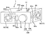
そこで、本実施例のプロジェクタ1には、図10に示すように4つの煙センサー61a,b,c,dと、4つの温度センサー62a,b,c,dとを備えている。
具体的には、煙センサー61aと温度センサー62aは、投射レンズ15が設けられた側面の投射レンズ15と排気口18との間に配置され、煙センサー61bと温度センサー62bは、操作部11が設けられた側面の略中央に設けられている。また、煙センサー61cと温度センサー62cは、吸気口16が設けられた側面のスピーカー65の近傍に設けられ、煙センサー61dと温度センサー62dは、装置本体100内(筐体部106内)に設けられている。
すなわち、本実施例のプロジェクタ1には、その設置可能な設置状態に対応した複数の箇所に煙センサー61及び温度センサー62設けらている。また、装置本体100内にも煙センサー61d及び温度センサー62dが設けられている。
Therefore, the
Specifically, the
That is, the
そして、4つの煙センサー61a,b,c,dはいずれも煙検知部151に接続され、煙検知部151は各煙センサー61毎の検出結果を信号に変換し本体制御部110に送信する。このように送信することで、本体制御部110は装置本体100のどの箇所に設けられた煙センサー61で、どの程度の煙を検知したかを区別して判断できる。
また、4つの温度センサー62a,b,c,dはいずれも温度検知部152に接続され、温度検知部152は各温度センサー62毎の検出結果を信号に変換し本体制御部110に送信する。このように送信することで、本体制御部110は装置本体100のどの箇所に設けられた温度センサー62で、どの程度の温度を検知したかを区別して判断できる。
The four
The four
上記のように、煙センサー61a,b,c,dを、プロジェクタ1の設置可能な複数の設置状態に対応した、プロジェクタ1の複数の箇所に設けることで、プロジェクタ1が、いずれの設置状態で設置されても、次のような効果を奏することができる。
装置本体100内や装置本体100近傍での内部要因による発煙、及び装置本体100周辺での外部要因による発煙の煙を、特定の箇所にだけ煙センサーを設た構成に比べて、より早期に精度良く区別して判定することが可能となる。
As described above, by providing the
Smoke generated by internal factors in and near the device
また、温度センサー62a,b,c,dを、プロジェクタ1のは、プロジェクタ1の複数の箇所に設けることで、プロジェクタ1が、いずれの設置状態で設置されても、次のような効果を奏することができる。
装置本体100や装置本体100近傍の内部要因による異常な温度上昇などの温度はもとより、装置本体100内の温度の異常上昇を、特定の箇所にだけ温度検知手段を設た構成に比べて、各箇所毎に精度良く区別して判定することが可能となる。このため、装置本体100内や装置本体100近傍での内部要因による発煙、及び装置本体100周辺での外部要因による発煙発煙の煙を、特定の箇所にだけ温度検知手段を設た構成に比べて、より早期に精度良く区別して判定することが可能となる。
また、装置本体100内や装置本体100近傍の温度が異常上昇している箇所の特定も可能となる。このため、装置本体100内のいずれかの構成部材や光路上に配置された遮蔽物が、異常加熱により故障したり、発煙したりする前にプロジェクタ1の稼動を停止することも可能となる。
Further, by providing the
Compared with the configuration in which the temperature detection means is provided only at a specific location, the temperature rise in the device
In addition, it is possible to specify a location where the temperature in the apparatus
ここで、上記した本実施例では、プロジェクタ1の設置可能な設置状態に対応した複数の箇所に煙センサー61及び温度センサー62設け、且つ装置本体100内にも煙センサー61d及び温度センサー62dを設けた構成に、本発明を適用した例について説明した。
しかし、本発明は、このような構成に限定されるものではなく、例えば、煙センサー61だけを複数設けた構成や、温度センサー62だけを複数設けた構成にも適用可能である。また、複数設けるセンサーのいずれかを、装置本体100の筐体部106の側面等にだけ設ける構成にも適用可能である。また、複数設けるセンサーのいずれかを、装置本体100の鏡胴部105における、投射レンズ15から投射される投射光の光路上に支障しない位置に設けることも可能である。
In this embodiment, the
However, the present invention is not limited to such a configuration, and can be applied to, for example, a configuration in which only a plurality of
(実施例3)
本実施形態のプロジェクタ1の実施例3について、図を用いて説明する。
図11は、本実施例のプロジェクタ1の煙センサー61、温度センサー62、物体センサー63等の配置説明図、図12は、本実施例の制御関係のブロック図である。
(Example 3)
Example 3 of the
FIG. 11 is an explanatory diagram of the arrangement of the
本実施例のプロジェクタ1と、上記した実施例1、2のプロジェクタとでは、本実施例のプロジェクタ1に煙センサー61、及び温度センサー62に加え、遮蔽物を検知するための物体センサー63を備えていることに係る点のみ異なる。
したがって、上記した実施例1、2で説明した用語や、各用語に付した符号等については、特に区別する必要がない限り、同一の用語や符号を用いて説明する。また、実施例1、2で説明した構成や、その作用や効果についても、同様なものは、適宜、省略して説明する。
In the
Therefore, the terms described in the first and second embodiments and the reference numerals assigned to the respective terms will be described using the same terms and reference numerals unless particularly distinguished. In addition, the configurations described in
図11に示すように、本実施例のプロジェクタ1には、投射レンズ15と排気口18との間に、煙センサー61aを上に、温度センサー62aを下に設けている。そして、これらの間に、スクリーン310と投射レンズ15との間に配置された遮蔽物(物体)を検出する物体センサー63を設けた。
この物体センサー63は、スクリーン310と投射レンズ15との間に配置された遮蔽物までの距離に応じた値を出力するとともに、図12に示す物体検知部153に接続されている。そして、物体検知部153は、物体センサー63の検出結果を信号に変換して本体制御部110に送信する。つまり、物体センサー63が接続された物体検知部153が、スクリーン310と投射レンズ15との間に配置された遮蔽物を検知する物体検知手段として機能する。
As shown in FIG. 11, the
The
そして、本体制御部110で実行される判定プログラムは、物体センサー63が接続された物体検知部153の検知結果に基づいて、煙センサー61が接続された煙検知部151で煙を検知した場合に、遮蔽物が要因で発煙が生じているか否かを判定する。
このよう構成することで、次のような効果を奏することができる。
投影光の光路上に配置された遮蔽物からの発煙と、装置本体100内の温度が異常上昇して故障した構成部材からの発煙や、装置本体100周辺での外部要因による発煙とを、上記のような物体検知手段を設けていない構成に比べて、早期に区別して判定できる。
また、物体センサー63が接続された物体検知部153と温度センサー62が接続された温度検知部152との検知結果に基づいて、投影光の光路上に配置された遮蔽物からの発煙が発生する前に、警告や情報の出力を行うことも可能となる。
The determination program executed by the main
With this configuration, the following effects can be achieved.
The smoke generated from the shielding object disposed on the optical path of the projection light, the smoke generated from the component that has failed due to the abnormal increase in the temperature in the apparatus
In addition, based on the detection results of the object detection unit 153 to which the
(実施例4)
本実施形態のプロジェクタ1の実施例4について、図を用いて説明する。
図13は、本実施例の光源部20に煙センサー61を設けるときに、光源21として高圧水銀ランプを有した場合の煙センサー61の説明図である。図14は、本実施例の光源部20に煙センサー61を設けるときに、光源21として複数の発光素子71を有した場合の煙センサー61の説明図である。
Example 4
Example 4 of the
FIG. 13 is an explanatory diagram of the
図15は、本実施例の光源部20に煙センサー61を設けるときに、光源21の漏れ光を受光部である受光素子67で受光する煙センサー61の説明図である。そして、図15(a)が、煙センサー61の受光素子67を保持する受光センサー66の、ランプフード23に対する配置説明図、図15(b)が、受光素子67を保持する受光センサー66の説明図である。
FIG. 15 is an explanatory diagram of the
本実施例のプロジェクタ1と、上記した実施例1乃至3のプロジェクタとでは、本実施例のプロジェクタ1の光源部20に設けた煙センサー61に係る点のみ異なる。
したがって、上記した実施例1乃至3で説明した用語や、各用語に付した符号等については、特に区別する必要がない限り、同一の用語や符号を用いて説明する。また、実施例1乃至3で説明した構成や、その作用や効果についても、同様なものは、適宜、省略して説明する。
The
Accordingly, the terms described in the first to third embodiments and the reference numerals assigned to the terms will be described using the same terms and reference numerals unless otherwise distinguished. In addition, the configurations described in
本実施例のプロジェクタ1では、少なくとも光源部20に煙検知手段である煙検知部151に接続する煙センサー61を設けることとした。
ここで、光源部20に設ける光源21としては、図3に示したように、高圧水銀ランプ等のランプを有した構成や、LED等の発光素子を有した構成をとることができる。また、レーザーや、LED等の発光素子とレーザーとを用いた光源(ハイブリッド光源)を有した構成をとることができる。
そこで、光源21として高圧水銀ランプを有した構成と、発光素子であるLED素子(以下、単に発光素子という)を複数有した構成とに、それぞれ、本発明を適用した例について説明する。
In the
Here, as the
Therefore, an example in which the present invention is applied to a configuration having a high-pressure mercury lamp as the
(高圧水銀ランプ)
まず、光源21として高圧水銀ランプを用いた構成に本発明を適用した例について、図13を用いて説明する。
図13に示すように、光源21として高圧水銀ランプを有した構成では、光源21から照射した光は、ランプフード23内を通過して集光レンズ24により集光され、カラーホイール25、ライトトンネル27、及び2つのリレーレンズ28を通過する(図3参照)。リレーレンズ28を通過した光は、画像生成部30で、平面ミラー31及び凹面ミラー32を介して、DMD素子33に照射されて所望の投影画像(投影光)が生成される(図3参照)。そして、投射光学部40で複数のレンズを通過して投射レンズ15からスクリーン310に投影される投影光となる。
(High pressure mercury lamp)
First, an example in which the present invention is applied to a configuration using a high-pressure mercury lamp as the
As shown in FIG. 13, in the configuration having a high-pressure mercury lamp as the
この光源21として高圧水銀ランプを有した構成では、図13に示すように、ランプフード23に、装置本体100の吸気口16から吸気した空気を排気口18に導けるように、2つの開口を設けている。これら2つの開口の内、吸気側の開口に、遮光板73を介して、煙センサー61の受光部として機能する受光素子67を有した受光センサー66を設けている。
そして、受光センサー66には、吸気口16から吸気した空気を、通過させる流路が形成されており、この流路に略直行するするとともに、流路から離れた箇所に受光素子67が設けられている。
このように構成することで、光源21から照射される光を直接受光することがない位置に、受光センサー66の受光素子67を配置するようにしている。
In the configuration having the high-pressure mercury lamp as the
The
With this configuration, the
ここで、受光センサー66に形成した流路、及びランプフード23内を通過する空気に煙等が含まれていない場合には、光源21から照射される光を受光素子67で受光することはできない。しかし、受光センサー66に形成した流路を通過する空気に、装置本体100周辺、又は装置本体100内や装置本体100近傍で発煙した煙が含まれている場合には、含まれた煙による散乱光がランプフード23内で生じて、受光素子67に受光されることとなる。
すなわち、この光源21として高圧水銀ランプを有した構成では、光源21を発光源として用いて、煙による散乱光を受光する光電方式の煙センサー61を構成している。
なお、上記したように、遮光板73を介して受光センサー66を設けるのは、光源21、ランプフード23の開口位置、及び受光センサー66の流路等の加工誤差や組付け誤差を吸収して、受光素子67で煙による散乱光を適切に受光するためである。
Here, when the flow path formed in the
That is, in the configuration having a high-pressure mercury lamp as the
As described above, the
上記のように、煙による散乱光を利用して煙を検知することで、次のような効果を奏することができる。
煙検知手段に用いる煙センサーの発光源を、プロジェクタ1の光源部20の光源21で兼ねることができ、煙センサー用(煙検知手段用)に新たな発光源を設けることなく部品点数削減、及び装置の小型化を図ることができる。
したがって、低コスト、及び装置本体100の小型化を図りながら、装置本体100内や装置本体100近傍での内部要因による発煙や、装置本体100周辺での外部要因による発煙を判定できるプロジェクタ1を提供できる。
As described above, the following effects can be achieved by detecting smoke using scattered light from smoke.
The light source of the smoke sensor used for the smoke detection means can also serve as the
Therefore, it is possible to provide a
また、この光源21として高圧水銀ランプを有した構成では、画像投影を行わないスタンバイ状態においても、光源21を所定の光量だけを発光させる。
このように、スタンバイ状態においても、光源21を所定の光量だけを発光させることで、次のような効果を奏することができる。
スタンバイ状態においても、装置本体100内や装置本体100近傍での内部要因による発煙や、装置本体100周辺での外部要因による発煙を判定することが可能となる。
Further, in a configuration having a high-pressure mercury lamp as the
As described above, even in the standby state, the following effects can be achieved by causing the
Even in the standby state, it is possible to determine smoke generation due to internal factors in the apparatus
(発光素子)
次に、光源21として複数の発光素子を有した構成に本発明を適用した例について、図14を用いて説明する。
図14に示すように、光源21として複数の発光素子71を有した構成では、複数の発光素子71からの光を、それぞれ小型レンズ72により集光して、集光レンズ24へと導く。そして、上記した光源として高圧水銀ランプを有した構成と同様に、光源21に有した複数の発光素子71から照射した光は、投射レンズ15からスクリーン310に投影される投影光となる。
(Light emitting element)
Next, an example in which the present invention is applied to a configuration having a plurality of light emitting elements as the
As shown in FIG. 14, in the configuration having a plurality of
また、光源21として複数の発光素子71を有した構成でも、図14に示すように、ランプフード23に、装置本体100の吸気口16から吸気した空気を排気口18に導けるように、2つの開口を設けている。これら2つの開口の内、吸気側の開口に、遮光板73を介して、煙センサー61の受光部として機能する受光素子67を有した受光センサー66を設けている。
そして、受光センサー66には、吸気口16から吸気した空気を、真直ぐ通過させる流路が形成されており、この流路に略直行するするとともに、流路から離れた箇所に受光素子67が設けられている。
このように構成することで、光源21から照射される光を直接受光することがない位置に、受光センサー66の受光素子67を配置するようにしている。
そして、複数の発光素子71を光源21として用いた構成でも、上記した高圧水銀ランプを光源21として用いた構成と同様に、光源21を発光源として用いて、煙による散乱光を受光する光電方式の煙センサー61を構成している。
Further, even in a configuration having a plurality of
The
With this configuration, the
Even in the configuration using the plurality of
上記のように、煙による散乱光を利用して煙を検知することで、上記した高圧水銀ランプを光源21として用いた構成と同様な効果を奏することができる。
加えて、以下に説明するような、複数の発光素子71を光源21として用いた構成での、特有の効果も奏することができる。
一般に、LED等の発光素子71を有した光源21は、高圧水銀ランプ等を用いる光源に比べて、長寿命、且つ、省電力である。
このように、一般に、高圧水銀ランプ等の光源に比べて、長寿命で省電力な発光素子71を複数有した光源21を用いることで、装置の省電力化に貢献できる。つまり、発光素子を用いることで、装置の省電力化に貢献できる。
As described above, by detecting the smoke using the scattered light from the smoke, the same effect as the configuration using the above-described high-pressure mercury lamp as the
In addition, a unique effect can be achieved in the configuration using a plurality of
In general, the
As described above, it is possible to contribute to power saving of the apparatus by using the
また、光源として高圧水銀ランプを有した構成とことなり、画像投影を行わないスタンバイ状態において、光源21の光量を少なくするときに、一部の発光素子71だけを発光させることができる。
このように、スタンバイ状態においても、一部の発光素子71だけを発光させることで、次のような効果を奏することができる。
高圧水銀ランプ等の1つの光源の光量を調整する構成に比べて、少ない光量を得るときに発光素子71の数を減らすことで調整でき、安定した光量を照射できるとともに、さらに装置の省電力化に貢献できる。
In addition, since the light source has a high-pressure mercury lamp, only a part of the
As described above, even in the standby state, by causing only some of the
Compared to a configuration that adjusts the light quantity of one light source such as a high-pressure mercury lamp, it can be adjusted by reducing the number of
また、発光さる発光素子71が故障した場合、光学制御部133の制御により、別の発光素子71を発光させることができる。
このように構成することで、装置本体100や装置本体100近傍での内部要因による発煙や、装置本体100周辺での外部要因による発煙の煙を安定して検知できる。したがって、装置本体100や装置本体100近傍での発煙と、装置本体100周辺での発煙とを、長期に亘り区別して判定することが可能となる。
また、故障した発光素子71の修理を、画像投影を行う予定の無いタイミングで行うことができ、実質的なダウンタイムを短縮することも可能となる。
When the
With this configuration, it is possible to stably detect smoke generated by internal factors in the apparatus
In addition, the repair of the failed
また、上記した本実施例では、光源21として高圧水銀ランプを有した構成と、発光素子を複数有した構成のいずれも、各部材の取付け誤差等を吸収して受光素子67を配置するため、遮光板73を介してランプフード23に受光センサー66を設けていた。また、ランプフード23に2つの開口を設け、これら2つの開口の内、吸気側の開口に、煙センサー61の受光部として機能する受光素子67を有した受光センサー66を設けていた。
しかし、本発明はこのような構成に限定されるものではなく、例えば、次のように構成することで、遮光板73を介することなく、各部材の取付け誤差等を吸収して、ランプフード23に受光センサー66を設けることができる。
In the above-described embodiment, both the configuration having the high-pressure mercury lamp as the
However, the present invention is not limited to such a configuration. For example, by configuring as follows, the
図15(a)に示すように、受光センサー66の受光素子67で受光する煙による散乱光が、図13、14に示したように、ランプフード23を介して、光源21から集光レンズ24に向う投射光ではなく、光源21からの漏れ光を利用するものである。
具体的には、図15(a)に示すようにランプフード23には、光源21からの漏れ光が通過する開口しか設けていない。そして、この漏れ光が通過する開口に直接、受光センサー66を取り付けている。
As shown in FIG. 15A, the scattered light from the smoke received by the
Specifically, as shown in FIG. 15A, the
この例の受光センサー66は、図15(b)に示すように、長手方向の一方の端部が閉じ、他方の端部に受光素子67を有した略矩形の断面を持つ。また、上記した受光センサーとは異なり、筒状部材のランプフード23に取り付ける側の長手方向に平行な側面に、光源21からの漏れ光が入射する窓(開口)を設けて透過率の高い耐熱ガラスで塞いでいる。一方、窓を設けた側面に直交する他長手方向に平行な2つの側面の窓近傍の部分には、煙を含み得る空気を通過させることができるように、吸気側と排気側の開口を対向して設けて流路を形成している。
そして、筒状部材の窓に設けた耐熱ガラスを光源21からの漏れ光が通過しても、漏れ光が直接、入射しない位置に受光素子67を設けている。
As shown in FIG. 15B, the
And even if the leak light from the
上記のように受光センサー66を構成することで、受光センサー66の吸気側と排気側の開口で形成される流路を通過する空気に煙が含まれていない場合には、光源21からの漏れ光を受光素子67で受光することはできない。しかし、受光センサー66の流路を通過する空気に、装置本体100周辺、又は装置本体100内や装置本体100近傍で発煙した煙が含まれている場合には、含まれた煙による散乱光が受光センサー66内で生じて、受光素子67に受光されることとなる。
すなわち、装置本体100周辺、又は装置本体100内や装置本体100近傍で発煙した煙を含みえる空気をランプフード23内を通過させることなく、光源21を発光源として用いて、煙による散乱光を受光する光電方式の煙センサー61を構成している。
By configuring the
That is, the air that can contain smoke generated around the apparatus
このように構成することで、ランプフード23への受光センサー66の取付け位置が多少変動しても、受光素子67で光源21からの漏れ光を受光することができ、遮光板73を設けることなく、光源21等を組み付け配置する場合の許容誤差を広げることができる。したがって、プロジェクタ1や、光源部20を組み付けるときの歩留まりを向上させることが可能となり、プロジェクタ1や、光源部20の低コスト化に貢献することができる。
また、集光レンズ24と光源21との間に設けたランプフード23を、煙を含み得る空気を通過させずに、受光素子67を有した受光センサー66内だけを煙を含み得る空気を通過させる構成も採用することができる。したがって、集光レンズ24や光源21が、煙や埃で汚れることを防止できる。
With this configuration, even if the mounting position of the
In addition, the
以上に説明したものは一例であり、本発明は、次の態様毎に特有の効果を奏する。
(態様A)
スクリーン310などの投影面に画像を投影するプロジェクタ1などの画像投影装置において、煙を検知する煙センサー61が接続された煙検知部151などの煙検知手段と、温度を検知する温度センサー62が接続された温度検知部152などの温度検知手段と、前記煙検知手段及び前記温度検知手段の検知結果に基づいて、装置本体100などの装置周辺での外部要因による発煙などの発煙が生じているか否かを判定する本体制御部110で実行される判定プログラムなどの判定手段と、を備えたことを特徴とするものである。
What has been described above is merely an example, and the present invention has a specific effect for each of the following modes.
(Aspect A)
In an image projection apparatus such as the
これによれば、上記実施例1(乃至4)について説明したように、次のような効果を奏することができる。
一般的に、装置周辺の発煙箇所で炎が大きくなる前は、発煙箇所で温度が異常上昇した空気が装置近傍に到達するよりも先に、発煙箇所の煙が装置近傍に到達する。
しかし、装置近傍に到達する煙は、装置周辺で発煙した煙だけでなく、次のように装置内や装置近傍での内部要因による発煙などの発煙による煙が到達する場合がある。
装置の吸気口16などの吸気口や排気口18などの排気口が遮蔽物で塞がれたり、投影光の光路が装置近傍に配置された遮蔽物で塞がれたりする場合がある。このような状態が継続されると、装置内の温度が異常上昇して装置内のいずれかの基板上の電解コンデンサなどの構成部材が破損して発煙したり、遮蔽物が加熱されて発煙したりする場合がある。
According to this, as described in the first embodiment (to 4), the following effects can be obtained.
In general, before the flame becomes large at the smoke generation area around the apparatus, the smoke at the smoke generation area reaches the vicinity of the apparatus before the air whose temperature has abnormally increased at the smoke generation area reaches the vicinity of the apparatus.
However, the smoke reaching the vicinity of the apparatus is not limited to the smoke generated around the apparatus, but may be caused by smoke such as smoke generated by internal factors in the apparatus or in the vicinity of the apparatus as follows.
There are cases where the intake port such as the
上記のように装置や装置近傍での発煙も生じ得るため、装置周辺での発煙が生じているか否かを適切に判定するためには、発煙箇所が装置周辺であるか、装置内や装置近傍であるかを区別して判定する必要がある。
そこで、判定手段では、煙検知手段及び温度検知手段の検出結果に基づいて、例えば、次のようにして判定することができる。
煙検知手段で煙を検知したときに、温度検知手段の検知結果が、画像投影装置の正常稼動時の装置内や装置近傍の温度の範囲を超える場合には、発煙箇所が装置内や装置近傍であると判定することができる。
また、煙検知手段で煙を検知したときに、温度検知手段の検知結果が画像投影装置の正常稼動時の装置内や装置近傍の温度の範囲を越えない場合には、発煙箇所が装置周辺であると判定することができる。
よって、装置周辺での発煙の有無を判定できる画像投影装置を提供できる。
As described above, smoke may also be generated near the device or the device. Therefore, in order to appropriately determine whether or not smoke is generated around the device, it is necessary to determine whether the smoke emission location is around the device, within the device, or near the device. It is necessary to judge whether it is.
Therefore, the determination means can make the determination as follows based on the detection results of the smoke detection means and the temperature detection means, for example.
When smoke is detected by the smoke detection means, if the detection result of the temperature detection means exceeds the temperature range in or near the device during normal operation of the image projection device, the smoke generation location is in the device or near the device. It can be determined that
Also, when smoke is detected by the smoke detection means, if the detection result of the temperature detection means does not exceed the temperature range in or near the device during normal operation of the image projection device, the smoke emission area is around the device. It can be determined that there is.
Therefore, it is possible to provide an image projection apparatus that can determine the presence or absence of smoke around the apparatus.
(態様B)
(態様A)において、本体制御部110で実行される判定プログラムなどの前記判定手段は、プロジェクタ1などの装置や装置近傍での内部要因による発煙などの発煙が生じているか否かも判定し、前記装置周辺での発煙と、前記装置や前記装置近傍での発煙とに、それぞれ対応した当該画像投影装置の制御、及び警告や情報の出力を行うことを特徴とするものである。
(Aspect B)
In (Aspect A), the determination means such as a determination program executed by the main
これによれば、上記実施例1(乃至4)について説明したように、次のような効果を奏することができる。
装置内や装置近傍での内部要因による発煙である場合と、装置周辺での外部要因による発煙などの発煙である場合とで、それぞれ適した画像投影装置の制御、及び警告や情報の出力が行え、それぞれの被害の拡大を抑制できる。
例えば、装置内や装置近傍での発煙が生じていると判定した場合には、遮蔽物の除去を促す警告画像の画像投影や音声出力を行って所定時間だけ経過した後、稼動を停止するように画像投影装置を制御することが挙げられる。
また、装置周辺での発煙が生じていると判定した場合には、火元の消火や避難を促す警告画像の画像投影や音声出力を行って所定時間だけ経過した後、稼動を停止するように画像投影装置を制御することが挙げられる。
これらの処理を行うことで、画像投影装置の故障、遮蔽物の破損、及び遮蔽物からの煙等の被害が拡大することや、装置周辺の発煙箇所からの炎が大きくなって被害が拡大することを抑制することが可能となる。
According to this, as described in the first embodiment (to 4), the following effects can be obtained.
Appropriate control of the image projection device and output of warnings and information can be performed depending on whether smoke is caused by internal factors in or near the device, or smoke caused by external factors around the device. , Can suppress the spread of each damage.
For example, when it is determined that smoke is generated in or near the device, the operation is stopped after a predetermined time has passed since the projection of the warning image for prompting the removal of the shielding object and the sound output. And controlling the image projection apparatus.
In addition, when it is determined that smoke is generated around the device, the operation is stopped after a predetermined time has elapsed after projecting a warning image to prompt fire extinguishing or evacuating and outputting sound. Controlling the image projection apparatus can be mentioned.
By performing these processes, damage to the image projection device, damage to the shield, and smoke from the shield increase, and the flame from the smoke area around the device increases and damage increases. This can be suppressed.
(態様C)
(態様B)において、プロジェクタ1などの当該画像投影装置の投影機構部50などの画像投影手段を用いて、前記警告や前記情報の出力を行うことを特徴とするものである。
これによれば、上記実施例1(乃至4)について説明したように、次のような効果を奏することができる。
音声出力手段や通信手段を備えていない画像投影装置でも、装置内や装置近傍での内部要因による発煙などの発煙である場合と、装置周辺での外部要因による発煙などの発煙である場合とで、それぞれ適した画像投影装置の制御、及び警告や情報の出力が行える。
(Aspect C)
In (Aspect B), the warning or the information is output using an image projection unit such as the
According to this, as described in the first embodiment (to 4), the following effects can be obtained.
Even in image projection devices that are not equipped with audio output means or communication means, there are cases where smoke is generated due to internal factors in or near the device, and cases where smoke is generated due to external factors around the device. , Control of image projection apparatuses suitable for each, and output of warnings and information.
例えば、装置内や装置近傍での発煙が生じていると判定した場合には、遮蔽物の除去を促す警告画像の画像投影を行って所定時間だけ経過した後、稼動を停止するように画像投影装置を制御することが挙げられる。
また、装置周辺での発煙が生じていると判定した場合には、火元の消火や避難を促す警告画像の画像投影を行って所定時間だけ経過した後、稼動を停止するように画像投影装置を制御することが挙げられる。
したがって、音声出力手段や通信手段を備えていない画像投影装置においても、画像投影装置の故障、遮蔽物の破損、及び遮蔽物からの煙等の被害が拡大することや、装置周辺の発煙箇所からの炎が大きくなって被害が拡大することを抑制することが可能となる。
For example, when it is determined that smoke is generated in the apparatus or in the vicinity of the apparatus, the image projection is performed so that the operation is stopped after a predetermined time has elapsed after the projection of the warning image prompting the removal of the shielding object. Controlling the device can be mentioned.
In addition, when it is determined that smoke is generated around the apparatus, the image projection apparatus projects an image of a warning image prompting extinguishing or evacuating the fire source, and after a predetermined time has elapsed, stops the operation. Control.
Therefore, even in an image projection apparatus that does not include audio output means or communication means, the failure of the image projection apparatus, the breakage of the shield, and the damage such as smoke from the shield increase, It is possible to suppress the increase in damage caused by the increase in the flame.
(態様D)
(態様B)において、スピーカー65などの音声出力手段、及び送受信部143などの外部通信手段の少なくともいずれかを備え、プロジェクタ1などの当該画像投影装置の投影機構部50などの画像投影手段、前記音声出力手段、及び外部通信手段の少なくともいずれかを用いて、投影画像や音声などの前記警告や前記情報の出力を行うことを特徴とするものである。
これによれば、上記実施例1(乃至4)について説明したように、次のような効果を奏
することができる。
画像投影装置の構成に応じた、警告や情報の出力が行える。
(Aspect D)
In (Aspect B), at least one of an audio output unit such as a
According to this, as described in the first embodiment (to 4), the following effects can be obtained.
Warnings and information can be output according to the configuration of the image projection apparatus.
例えば、装置内や装置近傍での発煙が生じていると判定した場合には、遮蔽物の除去を促す警告画像の画像投影や音声出力を行って所定時間だけ経過した後、稼動を停止するように画像投影装置を制御することが挙げられる。
また、装置周辺での発煙が生じていると判定した場合には、火元の消火や避難を促す警告画像の画像投影や音声出力を行って所定時間だけ経過した後、稼動を停止するように画像投影装置を制御することが挙げられる。
そして、外部通信手段を用いる場合には、装置内や装置近傍、又は装置周辺で発煙している煙を検知した画像投影装置から、建物に備えた災害情報システムなどの外部機器等に情報を送信できる。このため、発煙の発生状況を詳しく他の部屋にも伝えることができ、装置周辺での発煙が生じている場合には、他の部屋での避難誘導等を開始して、火災による被害の拡大の抑制効果を高めることも可能となる。
For example, when it is determined that smoke is generated in or near the device, the operation is stopped after a predetermined time has passed since the projection of the warning image for prompting the removal of the shielding object and the sound output. And controlling the image projection apparatus.
In addition, when it is determined that smoke is generated around the device, the operation is stopped after a predetermined time has elapsed after projecting a warning image to prompt fire extinguishing or evacuating and outputting sound. Controlling the image projection apparatus can be mentioned.
When using external communication means, information is transmitted from the image projection device that detects smoke in the device, in the vicinity of the device, or around the device to an external device such as a disaster information system provided in the building. it can. For this reason, it is possible to tell the details of the state of smoke generation to other rooms. If smoke is generated around the equipment, evacuation guidance is started in other rooms to expand the damage caused by fire. It is also possible to increase the suppression effect.
(態様E)
(態様A)乃至(態様D)のいずれかにおいて、煙センサー61が接続された煙検知部151などの前記煙検知手段は、プロジェクタ1などの当該画像投影装置の設置可能な複数の設置状態に対応した、当該画像投影装置の複数の箇所に設けられていることを特徴とするものである。
これによれば、上記実施例2(乃至4)について説明したように、次のような効果を奏することができる。
画像投影装置は、床や机等の上に置く床置き、天井から吊り下げた支持台等の上に置く天吊りの上置き、天井から吊り下げた支持具に画像投影装置の底部を固定する天吊りの下置き等の複数の設置状態で設置される場合がある。
そして、いずれの設置状態で設置されても、装置内や装置近傍での内部要因による発煙などの発煙、及び装置周辺での外部要因による発煙などの発煙の煙を、特定の箇所にだけ煙検知手段を設た構成に比べて、より早期に精度良く区別して判定することが可能となる。
(Aspect E)
In any one of (Aspect A) to (Aspect D), the smoke detection unit such as the
According to this, as described in the second embodiment (to 4), the following effects can be obtained.
The image projection device can be placed on a floor or a desk, placed on a ceiling suspended on a support stand suspended from the ceiling, or the ceiling that fixes the bottom of the image projection device to a support suspended from the ceiling. It may be installed in multiple installation states such as hanging underneath.
Even if it is installed in any installation state, smoke is detected only at a specific location, such as smoke generated by internal factors in or near the device, and smoke generated by external factors around the device. Compared to the configuration provided with the means, it is possible to distinguish and make a determination earlier and more accurately.
(態様F)
(態様A)乃至(態様E)のいずれかにおいて、温度センサー62が接続された温度検知部152などの前記温度検知手段は、プロジェクタ1などの当該画像投影装置の複数の箇所に設けられていることを特徴とするものである。
(Aspect F)
In any one of (Aspect A) to (Aspect E), the temperature detection unit such as the
これによれば、上記実施例2(乃至4)について説明したように、次のような効果を奏することができる。
装置本体100などの装置や装置近傍の内部要因による異常な温度上昇などの温度はもとより、装置内の温度の異常上昇を、特定の箇所にだけ温度検知手段を設た構成に比べて、各箇所毎に精度良く区別して判定することが可能となる。このため、装置内や装置近傍での内部要因による発煙などの発煙、及び装置周辺での外部要因による発煙などの発煙の煙を、特定の箇所にだけ温度検知手段を設た構成に比べて、より早期に精度良く区別して判定することが可能となる。
また、装置内や装置近傍の温度が異常上昇している箇所の特定も可能となり、装置内のいずれかの構成部材や光路上に配置された遮蔽物が、異常加熱により故障したり、発煙したりする前に画像投影装置の稼動を停止することも可能となる。
According to this, as described in the second embodiment (to 4), the following effects can be obtained.
Compared with the configuration in which the temperature detection means is provided only at a specific location, not only the temperature such as an abnormal temperature rise due to an internal factor in the device such as the device
In addition, it is possible to identify the location where the temperature in the device or in the vicinity of the device is abnormally rising, and any structural member in the device or a shield placed on the optical path will fail or emit smoke due to abnormal heating. It is also possible to stop the operation of the image projection apparatus before the operation.
(態様G)
(態様A)乃至(態様F)のいずれかにおいて、プロジェクタ1などの当該画像投影装置の投射レンズ15などの投射レンズとスクリーン310などの投影面との間にある遮蔽物を検知する物体検知手段を備え、物体センサー63が接続された物体検知部153などの前記物体検知手段の検知結果に基づいて、本体制御部110で実行される判定プログラムなどの前記判定手段は、煙センサー61が接続された煙検知部151などの前記煙検知手段で煙を検知した場合に、前記遮蔽物が要因で発煙が生じているか否かを判定することを特徴とするものである。
これによれば、上記実施例3(乃至4)について説明したように、次のような効果を奏
することができる。
投影光の光路上に配置された遮蔽物からの発煙と、装置内の温度が異常上昇して故障した構成部材からの発煙や、装置周辺での外部要因による発煙などの発煙とを、物体検知手段を設けていない構成に比べて、早期に区別して判定できる。
また、物体検知手段と温度センサー62が接続された温度検知部152などの温度検知手段との検知結果に基づいて、投影光の光路上に配置された遮蔽物からの発煙が発生する前に、警告や情報の出力を行うことも可能となる。
(Aspect G)
In any one of (Aspect A) to (Aspect F), an object detection unit that detects a shielding object between a projection lens such as the
According to this, as described in the third embodiment (to 4), the following effects can be obtained.
Detects smoke from the shield placed on the optical path of the projected light, smoke from components that have failed due to abnormally high temperatures in the device, and smoke from external factors around the device. Compared to a configuration in which no means is provided, it is possible to distinguish and determine at an early stage.
Further, based on the detection result of the temperature detection means such as the
(態様H)
(態様A)乃至(態様G)のいずれかにおいて、煙センサー61が接続された煙検知部151などの前記煙検知手段は、画像投影を行う光源21などの光源から直接受光することのない位置に受光センサー66の受光素子67などの受光部を設け、煙による散乱光を受光する光電方式であることを特徴とするものである。
これによれば、上記実施例4について説明したように、次のような効果を奏することができる。
煙検知手段に用いる発光源を、画像投影装置の光源部で兼ねることができ、煙検知手段用に新たな発光源を設けることなく部品点数削減、及び装置の小型化を図ることができる。
したがって、低コスト、及び装置の小型化を図りながら、装置内や装置近傍での内部要因による発煙などの発煙や、装置周辺での外部要因による発煙などの発煙を判定できるプロジェクタ1などの画像投影装置を提供できる。
(Aspect H)
In any one of (Aspect A) to (Aspect G), the smoke detection unit such as the
According to this, as described in the fourth embodiment, the following effects can be obtained.
The light emission source used for the smoke detection means can also serve as the light source unit of the image projection apparatus, and the number of parts can be reduced and the apparatus can be reduced in size without providing a new light emission source for the smoke detection means.
Therefore, image projection such as the
(態様I)
(態様H)において、画像投影を行わないスタンバイ状態においても、光源21などの前記光源を所定の光量だけを発光させることを特徴とするものである。
これによれば、上記実施例4について説明したように、スタンバイ状態においても、装置内や装置近傍での内部要因による発煙などの発煙や、装置周辺での外部要因による発煙などの発煙を判定することが可能となる。
(Aspect I)
(Aspect H) is characterized in that the light source such as the
According to this, as described in the fourth embodiment, even in the standby state, it is determined whether smoke is generated due to internal factors in the apparatus or in the vicinity of the apparatus, or smoke is generated due to external factors around the apparatus. It becomes possible.
(態様J)
(態様H)又は(態様I)において、光源21などの前記光源は、複数の発光素子71などの発光素子を有したものであることを特徴とすることを特徴とするものである。
これによれば、上記実施例4について説明したように、一般に、高圧水銀ランプ等の光源に比べて、長寿命で省電力な発光素子を複数有した光源を用いることで、装置の省電力化に貢献できる。
(Aspect J)
In (Aspect H) or (Aspect I), the light source such as the
According to this, as described in the fourth embodiment, in general, compared with a light source such as a high-pressure mercury lamp, a light source having a plurality of light-emitting elements that have a longer life and save power can be used to save power in the apparatus. Can contribute.
(態様K)
(態様J)において、画像投影を行わないスタンバイ状態においても、一部の発光素子71などの発光素子だけを発光させることを特徴とすることを特徴とするものである。
これによれば、上記実施例4について説明したように、高圧水銀ランプ等の1つの光源の光量を調整する構成に比べて、少ない光量を得るときに発光素子の数を減らすことで調整でき、安定した光量を照射できるとともに、さらに装置の省電力化に貢献できる。
(Aspect K)
(Aspect J) is characterized in that only light-emitting elements such as some of the light-emitting
According to this, as described in Example 4 above, it can be adjusted by reducing the number of light emitting elements when obtaining a small amount of light compared to a configuration for adjusting the amount of light of one light source such as a high-pressure mercury lamp, It can irradiate a stable amount of light, and can further contribute to power saving of the apparatus.
(態様L)
(態様K)において、発光さる発光素子71などの発光素子が故障した場合、別の発光素子を発光させることを特徴とするものである。
これによれば、上記実施例4について説明したように、次のような効果を奏することができる。
装置本体100などの装置や装置近傍での内部要因による発煙などの発煙や、装置周辺での外部要因による発煙などの発煙の煙を安定して検知でき、装置や装置近傍での発煙と、装置周辺での発煙とを、長期に亘り区別して判定することが可能となる。
また、故障した発光素子の修理を、画像投影を行う予定の無いタイミングで行うことができ、実質的なダウンタイムを短縮することも可能となる。
(Aspect L)
In (Aspect K), when a light-emitting element such as the light-emitting
According to this, as described in the fourth embodiment, the following effects can be obtained.
Smoke such as smoke generated by internal factors in the apparatus and the vicinity of the apparatus
In addition, the repair of the failed light emitting element can be performed at a timing when the image projection is not scheduled, and the substantial downtime can be shortened.
(態様M)
(態様H)乃至(態様L)のいずれかにおいて、光源21などの前記光源の漏れ光を利用することを特徴とするものである。
(Aspect M)
In any one of (Aspect H) to (Aspect L), leakage light of the light source such as the
これによれば、上記実施例4について説明したように、次のような効果を奏することができる。
ランプフード23などの光源部への受光センサー66の受光素子67などの受光部の取付け位置が多少変動しても、光源21などの光源からの漏れ光を受光することができ、遮光板73を設けることなく、光源等を組み付け配置する場合の許容誤差を広げることができる。したがって、プロジェクタ1などの画像投影装置や、光源部20などの光源部を組み付けるときの歩留まりを向上させることが可能となり、画像投影装置や、光源部の低コスト化に貢献することができる。
また、集光レンズ24などの集光レンズと光源との間に設けたランプフード23などの構成部材内を、煙を含み得る空気を通過させずに、受光部を有した受光センサーなどの部材内だけを煙を含み得る空気を通過させる構成も採用することができる。したがって、集光レンズや光源が、煙や埃で汚れることを防止できる。
According to this, as described in the fourth embodiment, the following effects can be obtained.
Even if the mounting position of the light receiving portion such as the
Further, a member such as a light receiving sensor having a light receiving portion without allowing air that may contain smoke to pass through a component such as a
1 プロジェクタ
11 操作部
12 ズームレバー
13 ACインレット
14 入出力端子
15 投射レンズ
16 吸気口
17 吸気ファン
18 排気口
19 排気ファン
20 光源部
21 光源
23 ランプフード
24 集光レンズ
25 カラーホイール
26 ホイール駆動モータ
27 ライトトンネル
28 リレーレンズ
30 画像生成部
31 平面ミラー
32 凹面ミラー
33 DMD素子
40 投射光学部
50 投影機構部
61(a,b,c,d) 煙センサー
62(a,b,c,d) 温度センサー
63 物体センサー
65 スピーカー
66 受光センサー(煙センサー)
67 受光素子(煙センサー)
68 耐熱ガラス(煙センサー)
71 発光素子(LED光源)
72 小型レンズ(発光素子用)
73 遮光板(ランプフード)
100 装置本体
105 鏡胴部
106 筐体部
110 本体制御部
120 操作制御部
131 画像入力部
132 画像処理部
133 光学制御部
141 音声処理部
142 音声出力部
143 送受信部(構内LAN)
144 外部記憶部
145 ファン制御部
146 電源部
151 煙検知部
152 温度検知部
153 物体検知部
310 スクリーン
DESCRIPTION OF
67 Light receiving element (smoke sensor)
68 Heat-resistant glass (smoke sensor)
71 Light Emitting Element (LED Light Source)
72 Small lens (for light emitting element)
73 Shading plate (lamp hood)
DESCRIPTION OF
144
Claims (13)
煙を検知する煙検知手段と、
温度を検知する温度検知手段と、
前記煙検知手段及び前記温度検知手段の検知結果に基づいて、装置周辺での発煙が生じているか否かを判定する判定手段と、
を備えたことを特徴とする画像投影装置。 In an image projection apparatus that projects an image on a projection surface,
Smoke detection means for detecting smoke;
Temperature detection means for detecting temperature;
Based on the detection results of the smoke detection means and the temperature detection means, a determination means for determining whether or not smoke is generated around the apparatus,
An image projection apparatus comprising:
前記判定手段は、装置や装置近傍での発煙が生じているか否かも判定し、
前記装置周辺での発煙と、前記装置や前記装置近傍での発煙とに、それぞれ対応した当該画像投影装置の制御、及び警告や情報の出力を行うことを特徴とする画像投影装置。 The image projector according to claim 1,
The determination means also determines whether or not smoke is generated near the device or the device,
An image projection apparatus that controls the image projection apparatus corresponding to smoke generation around the apparatus and smoke generation near the apparatus and the vicinity of the apparatus, and outputs warnings and information.
当該画像投影装置の画像投影手段を用いて、前記警告や前記情報の出力を行うことを特徴とする画像投影装置。 The image projection apparatus according to claim 2,
An image projection apparatus that outputs the warning or the information using an image projection unit of the image projection apparatus.
音声出力手段、及び外部通信手段の少なくともいずれかを備え、
当該画像投影装置の画像投影手段、前記音声出力手段、及び外部通信手段の少なくともいずれかを用いて、前記警告や前記情報の出力を行うことを特徴とする画像投影装置。 The image projection apparatus according to claim 2,
Comprising at least one of audio output means and external communication means,
An image projection apparatus that outputs the warning or the information using at least one of an image projection unit, an audio output unit, and an external communication unit of the image projection apparatus.
前記煙検知手段の煙センサーは、当該画像投影装置の設置可能な複数の設置状態に対応した、当該画像投影装置の複数の箇所に設けられていることを特徴とする画像投影装置。 In the image projection device according to any one of claims 1 to 4,
The smoke sensor of the smoke detection means is provided at a plurality of locations of the image projection device corresponding to a plurality of installation states in which the image projection device can be installed.
前記温度検知手段の温度センサーは、当該画像投影装置の複数の箇所に設けられていることを特徴とする画像投影装置。 In the image projection device according to any one of claims 1 to 5,
The temperature sensor of the said temperature detection means is provided in the several location of the said image projector, The image projector characterized by the above-mentioned.
当該画像投影装置の投射レンズと投影面との間にある遮蔽物を検知する物体検知手段を備え、
前記物体検知手段の検知結果に基づいて、
前記判定手段は、前記煙検知手段で煙を検知した場合に、前記遮蔽物が要因で発煙が生じているか否かを判定することを特徴とする画像投影装置。 In the image projection device according to any one of claims 1 to 6,
An object detection means for detecting a shielding object between the projection lens and the projection surface of the image projection apparatus;
Based on the detection result of the object detection means,
The image projecting apparatus according to claim 1, wherein the determination unit determines whether or not smoke is generated due to the shield when the smoke detection unit detects smoke.
前記煙検知手段は、画像投影を行う光源から直接受光することのない位置に前記煙センサーの受光部を設け、煙による散乱光を受光する光電方式であることを特徴とする画像投影装置。 In the image projection device according to any one of claims 1 to 7,
2. The image projection apparatus according to claim 1, wherein the smoke detection means is a photoelectric system in which a light receiving portion of the smoke sensor is provided at a position where light is not directly received from a light source that performs image projection, and light scattered by smoke is received.
画像投影を行わないスタンバイ状態においても、前記光源を所定の光量だけを発光させることを特徴とする画像投影装置。 The image projection apparatus according to claim 8, wherein
An image projection apparatus, wherein the light source emits only a predetermined amount of light even in a standby state in which image projection is not performed.
前記光源は、複数の発光素子を有したものであることを特徴とすることを特徴とする画像投影装置。 The image projection apparatus according to claim 8 or 9,
The image projector according to claim 1, wherein the light source includes a plurality of light emitting elements.
画像投影を行わないスタンバイ状態においても、一部の発光素子だけを発光させることを特徴とすることを特徴とする画像投影装置。 The image projector according to claim 10.
An image projection apparatus characterized by causing only some of the light emitting elements to emit light even in a standby state in which image projection is not performed.
発光さる発光素子が故障した場合、別の発光素子を発光させることを特徴とする画像投影装置。 The image projection device according to claim 11,
An image projection apparatus characterized by causing another light emitting element to emit light when a light emitting element emitting light fails.
前記光源の漏れ光を利用することを特徴とする画像投影装置。 The image projector according to any one of claims 8 to 12,
An image projection apparatus using leakage light of the light source.
Priority Applications (1)
| Application Number | Priority Date | Filing Date | Title |
|---|---|---|---|
| JP2013259248A JP6300068B2 (en) | 2013-12-16 | 2013-12-16 | Image projection device |
Applications Claiming Priority (1)
| Application Number | Priority Date | Filing Date | Title |
|---|---|---|---|
| JP2013259248A JP6300068B2 (en) | 2013-12-16 | 2013-12-16 | Image projection device |
Publications (3)
| Publication Number | Publication Date |
|---|---|
| JP2015114653A true JP2015114653A (en) | 2015-06-22 |
| JP2015114653A5 JP2015114653A5 (en) | 2017-01-12 |
| JP6300068B2 JP6300068B2 (en) | 2018-03-28 |
Family
ID=53528465
Family Applications (1)
| Application Number | Title | Priority Date | Filing Date |
|---|---|---|---|
| JP2013259248A Expired - Fee Related JP6300068B2 (en) | 2013-12-16 | 2013-12-16 | Image projection device |
Country Status (1)
| Country | Link |
|---|---|
| JP (1) | JP6300068B2 (en) |
Cited By (3)
| Publication number | Priority date | Publication date | Assignee | Title |
|---|---|---|---|---|
| WO2018021041A1 (en) * | 2016-07-27 | 2018-02-01 | ソニー株式会社 | Electronic device and airflow control method |
| JP2020129017A (en) * | 2019-02-07 | 2020-08-27 | セイコーエプソン株式会社 | Projector control method, projector and projector system |
| WO2021002048A1 (en) * | 2019-07-04 | 2021-01-07 | マクセル株式会社 | Projection video display device and obstacle detection method |
Citations (6)
| Publication number | Priority date | Publication date | Assignee | Title |
|---|---|---|---|---|
| JPH05159171A (en) * | 1991-12-03 | 1993-06-25 | Nec Eng Ltd | Television receiver with fire reporting function |
| JPH06109631A (en) * | 1991-10-31 | 1994-04-22 | Hochiki Corp | Fire alarm |
| JP2004329390A (en) * | 2003-05-02 | 2004-11-25 | Seiko Epson Corp | Projector and evacuation guidance system |
| JP2005051931A (en) * | 2003-07-29 | 2005-02-24 | Nec Viewtechnology Ltd | Power source protective circuit |
| JP2012216012A (en) * | 2011-03-31 | 2012-11-08 | Nec Personal Computers Ltd | Power unit and electric appliance |
| JP2012252252A (en) * | 2011-06-06 | 2012-12-20 | Seiko Epson Corp | Projector |
-
2013
- 2013-12-16 JP JP2013259248A patent/JP6300068B2/en not_active Expired - Fee Related
Patent Citations (6)
| Publication number | Priority date | Publication date | Assignee | Title |
|---|---|---|---|---|
| JPH06109631A (en) * | 1991-10-31 | 1994-04-22 | Hochiki Corp | Fire alarm |
| JPH05159171A (en) * | 1991-12-03 | 1993-06-25 | Nec Eng Ltd | Television receiver with fire reporting function |
| JP2004329390A (en) * | 2003-05-02 | 2004-11-25 | Seiko Epson Corp | Projector and evacuation guidance system |
| JP2005051931A (en) * | 2003-07-29 | 2005-02-24 | Nec Viewtechnology Ltd | Power source protective circuit |
| JP2012216012A (en) * | 2011-03-31 | 2012-11-08 | Nec Personal Computers Ltd | Power unit and electric appliance |
| JP2012252252A (en) * | 2011-06-06 | 2012-12-20 | Seiko Epson Corp | Projector |
Cited By (6)
| Publication number | Priority date | Publication date | Assignee | Title |
|---|---|---|---|---|
| WO2018021041A1 (en) * | 2016-07-27 | 2018-02-01 | ソニー株式会社 | Electronic device and airflow control method |
| JP2020129017A (en) * | 2019-02-07 | 2020-08-27 | セイコーエプソン株式会社 | Projector control method, projector and projector system |
| JP7172683B2 (en) | 2019-02-07 | 2022-11-16 | セイコーエプソン株式会社 | Projector control method and projector |
| WO2021002048A1 (en) * | 2019-07-04 | 2021-01-07 | マクセル株式会社 | Projection video display device and obstacle detection method |
| JP2021012248A (en) * | 2019-07-04 | 2021-02-04 | マクセル株式会社 | Projection type video display device and obstacle detection method |
| JP7248527B2 (en) | 2019-07-04 | 2023-03-29 | マクセル株式会社 | Projection type image display device and obstacle detection method |
Also Published As
| Publication number | Publication date |
|---|---|
| JP6300068B2 (en) | 2018-03-28 |
Similar Documents
| Publication | Publication Date | Title |
|---|---|---|
| EP2034357B1 (en) | Image projection apparatus | |
| US8408716B2 (en) | Image projection apparatus | |
| US7367679B2 (en) | Light source for a display device | |
| JP6300068B2 (en) | Image projection device | |
| JP6070786B2 (en) | projector | |
| US20060187420A1 (en) | Projector and cooling module of the same | |
| WO2015111364A1 (en) | Image projection device, control method, and program | |
| JP2014106410A (en) | Image projection device | |
| JP2012003257A (en) | Projection type image display apparatus | |
| CN201041610Y (en) | Light shielding board structure with open hole for protection bar integrator | |
| JP5845803B2 (en) | projector | |
| JP2008233150A (en) | projector | |
| JP2008281970A (en) | Projector apparatus | |
| JP6283994B2 (en) | Image projection device | |
| JP6202382B2 (en) | Image projection device | |
| JP6167595B2 (en) | projector | |
| JP6283991B2 (en) | Light projection device | |
| JP6520238B2 (en) | Projector and projector control method | |
| JP2007333915A (en) | Projection display | |
| JP2011075732A (en) | Projection display device | |
| JP2015225275A (en) | Cooling structure, light source device, projection type display device, and cooling method | |
| JP2016080972A (en) | Light source device and image projection device | |
| JP2017090787A (en) | Image projection apparatus and image projection mechanism | |
| JP2007206604A (en) | projector | |
| JP2018005053A (en) | Image projection device, control method of image projection device and program |
Legal Events
| Date | Code | Title | Description |
|---|---|---|---|
| A521 | Request for written amendment filed |
Free format text: JAPANESE INTERMEDIATE CODE: A523 Effective date: 20161129 |
|
| A621 | Written request for application examination |
Free format text: JAPANESE INTERMEDIATE CODE: A621 Effective date: 20161208 |
|
| A131 | Notification of reasons for refusal |
Free format text: JAPANESE INTERMEDIATE CODE: A131 Effective date: 20170915 |
|
| A977 | Report on retrieval |
Free format text: JAPANESE INTERMEDIATE CODE: A971007 Effective date: 20170913 |
|
| A521 | Request for written amendment filed |
Free format text: JAPANESE INTERMEDIATE CODE: A523 Effective date: 20171114 |
|
| TRDD | Decision of grant or rejection written | ||
| A01 | Written decision to grant a patent or to grant a registration (utility model) |
Free format text: JAPANESE INTERMEDIATE CODE: A01 Effective date: 20180202 |
|
| A61 | First payment of annual fees (during grant procedure) |
Free format text: JAPANESE INTERMEDIATE CODE: A61 Effective date: 20180215 |
|
| R151 | Written notification of patent or utility model registration |
Ref document number: 6300068 Country of ref document: JP Free format text: JAPANESE INTERMEDIATE CODE: R151 |
|
| LAPS | Cancellation because of no payment of annual fees |