JP2015114392A - Developing roller, developing roller manufacturing method, process cartridge, and electrophotographic apparatus - Google Patents
Developing roller, developing roller manufacturing method, process cartridge, and electrophotographic apparatus Download PDFInfo
- Publication number
- JP2015114392A JP2015114392A JP2013254503A JP2013254503A JP2015114392A JP 2015114392 A JP2015114392 A JP 2015114392A JP 2013254503 A JP2013254503 A JP 2013254503A JP 2013254503 A JP2013254503 A JP 2013254503A JP 2015114392 A JP2015114392 A JP 2015114392A
- Authority
- JP
- Japan
- Prior art keywords
- developing roller
- surface layer
- meth
- acrylate
- silica particles
- Prior art date
- Legal status (The legal status is an assumption and is not a legal conclusion. Google has not performed a legal analysis and makes no representation as to the accuracy of the status listed.)
- Pending
Links
Images

Landscapes
- Dry Development In Electrophotography (AREA)
- Rolls And Other Rotary Bodies (AREA)
Abstract
【課題】現像剤に対する帯電付与性と、現像剤付着等を抑制する性能(耐フィルミング性)を高次元で合わせ持つ現像ローラを提供する。【解決手段】軸芯体と最表面に表面層を有するローラであって、該表面層がアクリル樹脂のマトリクス中にシリカ粒子が分散してなるナノコンポジット構造を有する。【選択図】 図1There is provided a developing roller having a high level of charge imparting property to a developer and performance (filming resistance) for suppressing the adhesion of the developer. A roller having a shaft core and a surface layer on the outermost surface, the surface layer having a nanocomposite structure in which silica particles are dispersed in an acrylic resin matrix. [Selection] Figure 1
Description
本発明は現像ローラ、現像ローラの製造方法、プロセスカートリッジ及び電子写真装置に関する。 The present invention relates to a developing roller, a developing roller manufacturing method, a process cartridge, and an electrophotographic apparatus.
電子写真方式の画像形成装置(以下、「電子写真装置」とも称する)に用いられる現像ローラは、潜像担持体と所定の接触幅をもって圧接または近接され、塗布ブレードによって形成されたトナーの薄層を担持する。よって、現像ローラは、柔軟で変形し易く、かつ耐セット性に優れると共に、現像剤に対する帯電付与性、及び現像剤付着等を抑制することが求められている。これらの要求に対して、従来から、現像ローラには、軸芯体の外周に、導電性を付与したゴム材料で形成された弾性体層、さらにその外周に樹脂材料で形成された層を設けたものが使用されている。 A developing roller used in an electrophotographic image forming apparatus (hereinafter also referred to as “electrophotographic apparatus”) is pressed or brought close to a latent image carrier with a predetermined contact width, and is a thin layer of toner formed by a coating blade. Is carried. Therefore, the developing roller is required to be flexible, easily deformed, and excellent in set resistance, and to suppress the charge imparting property to the developer, the developer adhesion, and the like. In response to these requirements, conventionally, the developing roller has been provided with an elastic body layer made of a rubber material imparted with conductivity on the outer periphery of the shaft core, and a layer made of a resin material on the outer periphery thereof. Are used.
特許文献1では、導電性ローラの塗膜層(表面層)に耐摩耗性に優れたアクリレート用いて、表面層の摩耗を抑制した導電性ローラが提案されている。また、特許文献2では、導電性ロールの表層にウレタン樹脂に半導電性粒子を添加した構成で、粒子にシリコーン成分やフッ素成分を含有させることで、トナー付着を抑制した導電性ロールが提案されている。
現像剤に対する帯電付与性と、現像剤付着等を抑制する性能(耐フィルミング性)を高次元で合わせ持つ現像ローラが求められている。ローラの最表面に、帯電付与性に優れたアクリル材料からなる表面層を用いた導電性ローラの構成がある。しかしながら、アクリル樹脂の表面層を持つ現像ローラは、耐摩耗性に優れる一方、表面層が硬く、表面層の表面に現像剤や現像剤成分が付着し易い。 There is a need for a developing roller that has a high level of both charge imparting property to the developer and performance (filming resistance) that suppresses adhesion of the developer and the like. There is a configuration of a conductive roller using a surface layer made of an acrylic material excellent in charge imparting property on the outermost surface of the roller. However, a developing roller having an acrylic resin surface layer is excellent in abrasion resistance, but the surface layer is hard and the developer and developer components are likely to adhere to the surface of the surface layer.
一方、ローラの最表面に、柔軟性に優れたウレタン樹脂を用いた現像ローラがあるが、必ずしも十分な帯電付与性が得られない。
ウレタン樹脂に帯電付与性を持つ粒子を添加した層を持つ構成があるが、ローラ表面が削れて粒子が露出し、現像剤が付着し易い。
粒子が露出した際の現像剤の付着を防ぐため、粒子にシリコーン成分やフッ素成分を含有させた導電性ロールが知られているが、シリコーン成分やフッ素成分を含有させたことで、十分な帯電付与性が得られ難い。
本発明の目的は、現像剤に対する帯電付与性と、現像剤付着等を抑制する性能(耐フィルミング性)を高次元で合わせ持つ現像ローラを提供することにある。
On the other hand, although there is a developing roller using a urethane resin having excellent flexibility on the outermost surface of the roller, sufficient charge imparting properties cannot always be obtained.
There is a configuration having a layer in which particles having a charge-imparting property are added to a urethane resin, but the roller surface is scraped to expose the particles, and the developer tends to adhere.
In order to prevent the developer from adhering when the particles are exposed, conductive rolls containing a silicone component or fluorine component in the particles are known. It is difficult to obtain impartability.
SUMMARY OF THE INVENTION An object of the present invention is to provide a developing roller having a high level of both charge imparting property to a developer and performance (filming resistance) that suppresses developer adhesion and the like.
本発明によれば、軸芯体と表面層とを有する現像ローラであって、該表面層がアクリル樹脂のマトリクス中にシリカ粒子が分散してなるナノコンポジット構造を含有することを特徴とする現像ローラが提供される。
また本発明によれば、軸芯体と表面層とを有する現像ローラの製造方法であって、シリカ粒子のコアと、アクリル樹脂を含むシェルとを有するコア−シェル構造を有する粒子を水性媒体に分散させてなる水性分散体の被膜を乾燥せしめて該表面層を形成する工程を有する現像ローラの製造方法が提供される。
According to the present invention, there is provided a developing roller having a shaft core and a surface layer, wherein the surface layer contains a nanocomposite structure in which silica particles are dispersed in an acrylic resin matrix. A roller is provided.
According to the present invention, there is also provided a method for producing a developing roller having a shaft core and a surface layer, wherein particles having a core-shell structure having a core of silica particles and a shell containing an acrylic resin are used as an aqueous medium. There is provided a method for producing a developing roller including a step of drying a coating film of an aqueous dispersion formed to form the surface layer.
また本発明によれば、電子写真装置の本体に着脱可能に構成されいるプロセスカートリッジであって、上記の現像ローラを有するプロセスカートリッジが提供される。
さらに本発明によれば、上記の現像ローラを有することを特徴とする電子写真装置が提供される。
According to the present invention, there is provided a process cartridge configured to be detachable from a main body of an electrophotographic apparatus, the process cartridge having the developing roller.
Furthermore, according to the present invention, there is provided an electrophotographic apparatus having the above developing roller.
本発明の現像ローラは、現像剤に対する帯電付与性と、現像剤付着等を抑制する性能(耐フィルミング性)を高次元で合わせ持つ。本発明の電子写真装置は、高品質な画像を継続して出力することが出来る。 The developing roller of the present invention has a high level of charge imparting property to the developer and performance (filming resistance) that suppresses adhesion of the developer and the like. The electrophotographic apparatus of the present invention can continuously output high-quality images.
以下に、本発明をより詳細に説明する。
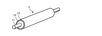
本発明の現像ローラは、軸芯体と、表面層とを有している。本発明の現像ローラの実施形態の一例を図1に示す。
図1は、本発明の現像ローラの一例の全体構成を模式的に示す図である。現像ローラ1は、中心に軸芯体11と、該軸芯体の外周面に順次、弾性体層12及び表面層13を有している。
図2は、現像ローラ1を軸芯体11の中心線を含む断面図を模式的に示す図である。本発明の現像ローラは、表面層13がアクリル樹脂のマトリクス中にシリカ粒子が分散してなるナノコンポジット構造を含有している。
Hereinafter, the present invention will be described in more detail.
The developing roller of the present invention has a shaft core and a surface layer. An example of an embodiment of the developing roller of the present invention is shown in FIG.
FIG. 1 is a diagram schematically showing an overall configuration of an example of the developing roller of the present invention. The developing
FIG. 2 is a diagram schematically showing a cross-sectional view of the developing
以下、弾性体層及び表面層を軸芯体上にこの順に積層した2層構造の現像ローラについて説明するが、本発明の現像ローラは、軸芯体外周上の層構成が、1層構成、及び3層上の多層構成を有するものであってもよい。例えば、軸芯体の外周面に表面層のみを有している構成、弾性体層と表面層の間に別の層(中間層)を設けた構成、弾性体層が複数の層である構成が挙げられる。構成によっては、本発明の効果に加えて、異なる性能を付加した現像ローラとすることが可能である。 Hereinafter, a developing roller having a two-layer structure in which an elastic body layer and a surface layer are laminated in this order on a shaft core will be described. The developing roller of the present invention has a one-layer structure on the outer periphery of the shaft core. And a multi-layer structure having three layers. For example, a configuration in which only the surface layer is provided on the outer peripheral surface of the shaft core, a configuration in which another layer (intermediate layer) is provided between the elastic layer and the surface layer, and a configuration in which the elastic layer is a plurality of layers Is mentioned. Depending on the configuration, in addition to the effects of the present invention, a developing roller having different performances can be provided.
<軸芯体>
軸芯体11は、現像ローラの支持部材であると共に、同時に電極として機能するものである。
<Shaft core>
The
<弾性体層>
現像ローラを二層以上の構成とし、本発明の表面層13とは別に弾性体層12を設けてもよい。弾性体層12を設ける場合、弾性体層は、柔軟性を有するものであり、原料ゴム、加硫剤及びその他の添加剤等からなる原料混合物を成型体として形成したものを用いることができる。
<Elastic body layer>
The developing roller may have two or more layers, and the
弾性体層に使用出来るゴム材料としては以下のものが挙げられる。アクリロニトリルブタジエンゴム(NBR)、エチレン−プロピレン−ジエン共重合ゴム(EPDM)、クロロプレンゴム、エピクロロヒドリンゴム、アクリロニトリルブタジエンゴムの水素化物、多硫化ゴム、天然ゴム、イソプレンゴム、スチレン−ブタジエンゴム、フッ素ゴム、シリコーンゴム、ウレタンゴム。
これらのゴムは、単独であるいは2種類以上を混合して用いてもよい。ブレンドする際、特に制限はないが、ブレンド時の相溶性、及び相容性を考慮する必要はある。一般に用いられるゴムの混合方法により、十分な相容性が得られることが好ましい。
Examples of the rubber material that can be used for the elastic layer include the following. Acrylonitrile butadiene rubber (NBR), ethylene-propylene-diene copolymer rubber (EPDM), chloroprene rubber, epichlorohydrin rubber, hydride of acrylonitrile butadiene rubber, polysulfide rubber, natural rubber, isoprene rubber, styrene-butadiene rubber, fluorine Rubber, silicone rubber, urethane rubber.
These rubbers may be used alone or in admixture of two or more. When blending, there is no particular limitation, but it is necessary to consider compatibility and compatibility during blending. It is preferable that sufficient compatibility is obtained by a generally used rubber mixing method.
また、これらのゴム材料に種々の添加剤などを必要に応じて配合して弾性体層を形成することができる。添加剤としては、現像ローラの用途に合わせて、弾性体層自体に要求される機能に必要な成分として、導電剤及び非導電性充填剤を、主成分のゴム材料に適宜配合しても良い。また、弾性体層自体をゴム成型体とする際に利用される成分として、架橋剤(加硫剤)、加硫促進剤又は加硫促進助剤を、主成分のゴム原料に適宜配合しても良い。 Moreover, various additives etc. can be mix | blended with these rubber materials as needed, and an elastic body layer can be formed. As additives, a conductive agent and a non-conductive filler may be appropriately blended into the main rubber material as components necessary for the function required for the elastic layer itself, depending on the use of the developing roller. . Further, as a component used when the elastic body layer itself is made into a rubber molded body, a crosslinking agent (vulcanizing agent), a vulcanization accelerator or a vulcanization acceleration assistant is appropriately blended in the main rubber material. Also good.
導電剤としては、炭素系導電剤、導電性金属の粉体、導電性合金の粉体、導電性ウィスカーが挙げられる。
炭素系導電剤として、次のものが挙げられる。カーボンブラック、グラファイト、カーボンナノチューブ。
導電性金属の粉体として、次のものが挙げられる。アルミニウムの粉体、銅の粉体、錫の粉体、ステンレス鋼の粉体。
導電性ウィスカーとして、次のものが挙げられる。カーボンウィスカー、黒鉛ウィスカー、炭化チタンウィスカー、導電性チタン酸カリウムウィスカー、導電性チタン酸バリウムウィスカー、導電性酸化チタンウィスカー、導電性酸化亜鉛ウィスカー。
これらの中でも、カーボンブラックは、比較的容易に入手可能で、また、主成分のゴム材料の種類によらず良好な導電性が得られるため、好ましい。
Examples of the conductive agent include carbon-based conductive agents, conductive metal powders, conductive alloy powders, and conductive whiskers.
The following are mentioned as a carbon-type electrically conductive agent. Carbon black, graphite, carbon nanotubes.
Examples of the conductive metal powder include the following. Aluminum powder, copper powder, tin powder, stainless steel powder.
Examples of conductive whiskers include the following. Carbon whisker, graphite whisker, titanium carbide whisker, conductive potassium titanate whisker, conductive barium titanate whisker, conductive titanium oxide whisker, conductive zinc oxide whisker.
Among these, carbon black is preferable because it is relatively easily available and good conductivity can be obtained regardless of the type of the main rubber material.
カーボンブラックは市販品、市販品を処理したもの、あるいは新規に製造されたもののいずれであってもよい。カーボンブラックとして、オイルファーネスブラック、ガスファーネスブラック、チャンネルタイプのカーボンブラックが挙げられる。これらのカーボンブラックに対し酸化処理を施したものも使用できる。
カーボンブラックの添加量としては、弾性体層を形成するゴム原料100質量部に対して、通常10質量部以上、80質量部以下である。カーボンブラックの種類にもよるが、10質量部以上で、十分かつ安定した導電性を付与し易く、80質量部以下で、所望とするゴム弾性が得られ易い。
その他、弾性体層に導電性を付与する手段として、導電性高分子化合物を使用することも可能である。
Carbon black may be a commercially available product, a product obtained by treating a commercially available product, or a newly produced product. Examples of carbon black include oil furnace black, gas furnace black, and channel type carbon black. Those obtained by oxidizing these carbon blacks can also be used.
The amount of carbon black added is usually 10 parts by mass or more and 80 parts by mass or less with respect to 100 parts by mass of the rubber raw material forming the elastic layer. Although depending on the type of carbon black, it is easy to impart sufficient and stable conductivity at 10 parts by mass or more, and desired rubber elasticity is easily obtained at 80 parts by mass or less.
In addition, as a means for imparting conductivity to the elastic body layer, a conductive polymer compound can be used.
非導電性充填剤としては、次のものが挙げられる。珪藻土,石英粉末,乾式シリカ,湿式シリカ,酸化チタン,酸化亜鉛,アルミノケイ酸,炭酸カルシウム。
架橋剤としては、次のものが挙げられる。ジ−t−ブチルパーオキサイド、2,5−ジメチル−2,5−ジ(t−ブチルパーオキシ)ヘキサン、ジクミルパーオキサイド、t−ブチルパーオキシベンゾエート、P−クロロベンゾイルパーオキサイド。
Non-conductive fillers include the following. Diatomaceous earth, quartz powder, dry silica, wet silica, titanium oxide, zinc oxide, aluminosilicate, calcium carbonate.
The following are mentioned as a crosslinking agent. Di-t-butyl peroxide, 2,5-dimethyl-2,5-di (t-butylperoxy) hexane, dicumyl peroxide, t-butylperoxybenzoate, P-chlorobenzoyl peroxide.
弾性体層を形成するゴム組成物は、通常の場合、一般のゴムを加硫するときと同様に、未架橋の配合ゴムを一度調製し、次いでこの配合ゴムを意図する形状に成形したのち、架橋(加硫)を行うことにより製造される。
加硫剤としては、有機過酸化物、硫黄、硫黄化合物、含硫黄有機加硫剤又はトリアジン系化合物が用いられるが、特に硫黄又は硫黄化合物が好ましい。
The rubber composition for forming the elastic layer is usually prepared by preparing an uncrosslinked compounded rubber once and then molding the compounded rubber into the intended shape in the same manner as when vulcanizing general rubber. Manufactured by crosslinking (vulcanization).
As the vulcanizing agent, organic peroxides, sulfur, sulfur compounds, sulfur-containing organic vulcanizing agents or triazine compounds are used, and sulfur or sulfur compounds are particularly preferable.
硫黄系加硫剤(硫黄、硫黄化合物)としては、次のものが挙げられる。粉末硫黄、硫黄華、高分散性硫黄、不溶性硫黄、沈降硫黄、表面処理硫黄、コロイド硫黄、塩化硫黄、一塩化硫黄、二塩化硫黄。
含硫黄有機加硫剤としては、次のものが挙げられる。モルホリンジスルフィド、アルキルフェノールジスルフィド類、チウラムジスルフィド、N,N′−ジチオ−ビス(ヘキサヒドロ−2H−アゼピノン−2)、2−(4′−モルホリノジチオ)ベンゾチアゾール。以上の加硫剤は、1種使用するかあるいは2種以上を併用することができる。
Examples of the sulfur vulcanizing agent (sulfur, sulfur compound) include the following. Powdered sulfur, sulfur flower, highly dispersible sulfur, insoluble sulfur, precipitated sulfur, surface treated sulfur, colloidal sulfur, sulfur chloride, sulfur monochloride, sulfur dichloride.
The following are mentioned as a sulfur-containing organic vulcanizing agent. Morpholine disulfide, alkylphenol disulfides, thiuram disulfide, N, N'-dithio-bis (hexahydro-2H-azepinone-2), 2- (4'-morpholinodithio) benzothiazole. The above vulcanizing agents can be used alone or in combination of two or more.
これらの加硫剤の配合量は、ゴム原料100質量部に対し、通常、0.1質量部以上15質量部以下、好ましくは0.5質量部以上10質量部以下である。
加硫剤として、硫黄系加硫剤を使用する場合には、有機系加硫促進剤を併用することができる。このような加硫促進剤としては、次のものが挙げられる。アルデヒドアンモニア類、アルデヒドアミン類、グアニジン塩類、イミダゾリン類、チアゾール類、スルフェンアミド類、チオ尿素類、ジチオカルバミン酸塩類、チウラム類、ザンテート類。加硫促進剤は、1種で使用するか、あるいは2種以上を併用することができる。加硫促進剤の配合量は、ゴム原料100質量部に対し、通常、0.1質量部以上20質量部以下、好ましくは0.2質量部以上10質量部以下である。
また、上記加硫剤および有機系加硫促進剤に加え、必要に応じて、無機系加硫促進助剤を添加することもできる。
The compounding amount of these vulcanizing agents is usually 0.1 parts by mass or more and 15 parts by mass or less, preferably 0.5 parts by mass or more and 10 parts by mass or less with respect to 100 parts by mass of the rubber raw material.
When a sulfur vulcanizing agent is used as the vulcanizing agent, an organic vulcanization accelerator can be used in combination. Examples of such vulcanization accelerators include the following. Aldehyde ammonia, aldehyde amines, guanidine salts, imidazolines, thiazoles, sulfenamides, thioureas, dithiocarbamates, thiurams, xanthates. One vulcanization accelerator can be used, or two or more vulcanization accelerators can be used in combination. The compounding amount of the vulcanization accelerator is usually 0.1 parts by mass or more and 20 parts by mass or less, preferably 0.2 parts by mass or more and 10 parts by mass or less with respect to 100 parts by mass of the rubber raw material.
In addition to the vulcanizing agent and the organic vulcanization accelerator, an inorganic vulcanization accelerating aid may be added as necessary.
ゴム組成物には、さらに以下のものを配合できる。紫外線吸収剤、光安定剤、難燃剤、帯電防止剤、液状ゴム、官能基含有オリゴマー、着色剤、耐油性向上剤、発泡剤、スコーチ防止剤、粘着付与剤、脱水剤、活性剤、ワックス、カップリング剤、素練り促進剤、抗菌剤、発泡助剤、又は加工助剤。
なお、現像ローラを潜像担持体に当接して使用する場合、当接する際に均一なニップ幅を確保するために、弾性体層の厚さは、0.5mm以上が好ましく、1.0mm以上とすることがより好ましい。現像ローラの外径精度を損なわない限り、弾性体層の厚さに特に制限はないものの、弾性体層の厚さは、好ましくは6.0mm以下、より好ましくは5.0mm以下とするのがよい。
The following can be further blended in the rubber composition. UV absorber, light stabilizer, flame retardant, antistatic agent, liquid rubber, functional group-containing oligomer, colorant, oil resistance improver, foaming agent, scorch inhibitor, tackifier, dehydrating agent, activator, wax, Coupling agent, peptizer, antibacterial agent, foaming aid, or processing aid.
When the developing roller is used in contact with the latent image carrier, the thickness of the elastic layer is preferably 0.5 mm or more and 1.0 mm or more in order to ensure a uniform nip width at the time of contact. More preferably. The thickness of the elastic layer is not particularly limited as long as the outer diameter accuracy of the developing roller is not impaired, but the thickness of the elastic layer is preferably 6.0 mm or less, more preferably 5.0 mm or less. Good.
弾性体層の硬度(Asker−C)は、通常、40°以上80°以下が好ましい。現像ローラの硬度は、表面層の厚みや材質にもよるが、弾性体層の硬度(Asker−C)が、40°以上では、適当なゴム弾性が得られ易く、一方、80°以下では、適切なニップ幅を得られ易い。弾性体層を形成するゴム成型体の硬度(Asker−C)は、45°以上70°以下の範囲に選択することがより好ましい。 The hardness (Asker-C) of the elastic layer is usually preferably 40 ° or more and 80 ° or less. The hardness of the developing roller depends on the thickness and material of the surface layer, but when the hardness of the elastic layer (Asker-C) is 40 ° or more, suitable rubber elasticity is easily obtained, while on the other hand, at 80 ° or less, It is easy to obtain an appropriate nip width. The hardness (Asker-C) of the rubber molded body forming the elastic layer is more preferably selected in the range of 45 ° to 70 °.
<表面層>
本発明の現像ローラは、表面層13を有している。例えば、弾性体層12の外側に、表面層13が積層されている。表面層13は、アクリル樹脂のマトリクス中にシリカ粒子が分散してなるナノコンポジット構造を含有する組成物で形成されている。
ナノコンポジット構造とは、一般的には、ある素材をナノオーダー(1〜100nm次元)で粒子化したものを、別の素材に練り込み、分散させた「複合材料」を指す。ナノコンポジット構造を形成することで、引張強さ、弾性率、熱変形温度などの物性変化がみられる。
<Surface layer>
The developing roller of the present invention has a
The nanocomposite structure generally refers to a “composite material” obtained by kneading and dispersing a material obtained by particleizing a certain material on the nano order (1 to 100 nm dimension) into another material. By forming a nanocomposite structure, changes in physical properties such as tensile strength, elastic modulus, and heat distortion temperature are observed.
本発明に用いる「アクリル樹脂のマトリクス中にシリカ粒子が分散してなるナノコンポジット構造」とは、ナノオーダーのシリカ粒子が、アクリル樹脂中に分散している構造である。この構造を取ることにより、従来のアクリル樹脂をベースとした層に比べて、柔軟な表面層とすることが出来る。
アクリル樹脂は、透明性の高い非晶質の合成樹脂であるが、相対的に高硬度で、衝撃性に弱い性質を併せ持つ。アクリル樹脂の硬度は、その化学構造自体に依るところが大きく、現像ローラの表面層として用いた場合、高硬度のため弊害を起こし易い。
The “nanocomposite structure in which silica particles are dispersed in an acrylic resin matrix” used in the present invention is a structure in which nano-order silica particles are dispersed in an acrylic resin. By adopting this structure, the surface layer can be made more flexible than a conventional acrylic resin-based layer.
Acrylic resin is an amorphous synthetic resin with high transparency, but has a relatively high hardness and weak impact resistance. The hardness of the acrylic resin largely depends on its chemical structure itself, and when used as a surface layer of a developing roller, it is likely to cause a harmful effect due to its high hardness.
本発明においては、アクリル樹脂に、シリカ粒子を分散させたナノコンポジット構造を取ることにより、樹脂の硬度を低下させることが出来る。この現象は、以下の如く推察している。
第一の理由は、アクリル樹脂中にシリカ粒子が分散されることにより、アクリル樹脂のみが存在する部分のサイズが小さくなり、アクリル樹脂の化学構造に由来する本来の性質の発現が変化、もしくは抑制されているものと考えられる。アクリル樹脂は非晶質であり、結晶のような長距離秩序はないが、短距離秩序はある。その短距離秩序の部分により、高い硬度を示すと考えられるが、ナノコンポジット構造をとる場合、その短距離秩序の形成を乱す、もしくは抑制する。
この短距離秩序は、微晶質、潜晶質と呼ばれるような構造に近いもので、光学的には結晶構造が見られないが、X線回折や、結晶融解熱では弱い結晶性を示すものと考えられる。この弱い結晶性を小さくすることにより、表面層としての硬度を低減させることが出来る。
In the present invention, the hardness of the resin can be reduced by taking a nanocomposite structure in which silica particles are dispersed in an acrylic resin. This phenomenon is presumed as follows.
The first reason is that the silica particles are dispersed in the acrylic resin, thereby reducing the size of the portion where only the acrylic resin is present, and changing or suppressing the expression of the original properties derived from the chemical structure of the acrylic resin. It is thought that. Acrylic resins are amorphous and do not have long-range order like crystals, but have short-range order. The short-range order part is considered to exhibit high hardness, but when the nanocomposite structure is adopted, the formation of the short-range order is disturbed or suppressed.
This short-range order is close to a structure called microcrystalline or latent crystalline, and does not show a crystalline structure optically, but exhibits weak crystallinity in X-ray diffraction or heat of crystal melting. it is conceivable that. By reducing the weak crystallinity, the hardness of the surface layer can be reduced.
第二の理由は、シリカ粒子に凝集塊がなく、良好な分散状態にあると考えられる。分散されたシリカ粒子は、ナノオーダーで分散しているため、表面層の硬度を必要以上に高くすることがない。シリカ粒子添加による硬度変化が小さいことにより、表面層中に部分的に高硬度となる部分(例えば、シリカの比率が高い部分)も少なくなる。
よって、アクリル樹脂が本来持つ、帯電付与性はそのままに、相対的に柔軟な表面層により現像剤付着等を抑制する性能(耐フィルミング性)を併せ持つことが出来る。
The second reason is considered that the silica particles do not have agglomerates and are in a good dispersion state. Since the dispersed silica particles are dispersed on the nano order, the hardness of the surface layer is not increased more than necessary. Since the change in hardness due to the addition of silica particles is small, the surface layer also has a portion with a high hardness (for example, a portion with a high silica ratio).
Therefore, it is possible to have the performance (filming resistance) of suppressing the adhesion of the developer and the like by the relatively flexible surface layer while maintaining the charge imparting property inherent in the acrylic resin.
さらには、ナノコンポジット構造としてシリカ粒子が良好に分散しているため、現像ローラとして経時で使用した時に、シリカ粒子の表面への露出による現像剤付着が起こり難い。この現象は、以下の如く推察している。
シリカ粒子が最小単位で分散している場合、シリカ粒子同士の凝集がないために、凝集破壊によるシリカ表面の露出自体が起こらない。また、仮にシリカ粒子が露出した場合でも、その露出面の大きさがナノオーダーであるため、現像剤付着は成長し難い。
よって、本発明の表面層を現像ローラに用いた場合、アクリル樹脂ベースであっても表面層が低硬度で、かつ、シリカ粒子表面への現像剤付着が起こり難いため、現像剤付着を抑制する性能(耐フィルミング性)を高次元で達成する。
Furthermore, since the silica particles are well dispersed as a nanocomposite structure, when the developer roller is used over time, developer adhesion due to exposure of the silica particles to the surface hardly occurs. This phenomenon is presumed as follows.
When the silica particles are dispersed in the minimum unit, the silica surface is not exposed due to cohesive failure because the silica particles are not aggregated. Even if the silica particles are exposed, the developer adhesion is difficult to grow because the size of the exposed surface is nano-order.
Therefore, when the surface layer of the present invention is used for the developing roller, even if it is an acrylic resin base, the surface layer is low in hardness and the developer does not easily adhere to the surface of the silica particles. Achieve performance (filming resistance) at a high level.
本発明に用いるアクリル樹脂とは、(メタ)アクリル系単量体を重合したものである。これらの単量体は単独で又は二種以上組み合わせて使用できる。
(メタ)アクリル系単量体としては、(メタ)アクリル酸アルキルエステル類、シクロアルキル(メタ)アクリレート、アラルキル(メタ)アクリレート、多環式(メタ)アクリレート、ヒドロキシル基含有(メタ)アクリル酸エステル類、アルコキシ基又はフェノキシ基含有(メタ)アクリル酸エステル類、エポキシ基含有(メタ)アクリル酸エステル類、ハロゲン含有(メタ)アクリル酸エステル類、(メタ)アクリルアミド類、アルキルアミノアルキル(メタ)アクリレートが挙げられ、具体的には、それぞれ以下のものが挙げられる。
The acrylic resin used in the present invention is obtained by polymerizing a (meth) acrylic monomer. These monomers can be used alone or in combination of two or more.
(Meth) acrylic monomers include (meth) acrylic acid alkyl esters, cycloalkyl (meth) acrylates, aralkyl (meth) acrylates, polycyclic (meth) acrylates, hydroxyl group-containing (meth) acrylic esters , Alkoxy group or phenoxy group-containing (meth) acrylic acid esters, epoxy group-containing (meth) acrylic acid esters, halogen-containing (meth) acrylic acid esters, (meth) acrylamides, alkylaminoalkyl (meth) acrylates Specifically, the following are mentioned respectively.
(メタ)アクリル酸アルキルエステル類としては、メチル(メタ)アクリレート、エチル(メタ)アクリレート、n−又はi−プロピル(メタ)アクリレート、2−メチル−2−ニトロプロピル(メタ)アクリレート、n−,i−,s−又はt−ブチル(メタ)アクリレート、n−又はt−ペンチル(メタ)アクリレート、3−ペンチル(メタ)アクリレート、2,2−ジメチルブチル(メタ)アクリレート、n−ヘキシル(メタ)アクリレート、セチル(メタ)アクリレート、n−オクチル(メタ)アクリレート、2−エチルヘキシル(メタ)アクリレート、4−メチル−2−プロピルペンチル(メタ)アクリレート、n−オクタデシル(メタ)アクリレート。 Examples of (meth) acrylic acid alkyl esters include methyl (meth) acrylate, ethyl (meth) acrylate, n- or i-propyl (meth) acrylate, 2-methyl-2-nitropropyl (meth) acrylate, n-, i-, s- or t-butyl (meth) acrylate, n- or t-pentyl (meth) acrylate, 3-pentyl (meth) acrylate, 2,2-dimethylbutyl (meth) acrylate, n-hexyl (meth) Acrylate, cetyl (meth) acrylate, n-octyl (meth) acrylate, 2-ethylhexyl (meth) acrylate, 4-methyl-2-propylpentyl (meth) acrylate, n-octadecyl (meth) acrylate.
シクロアルキル(メタ)アクリレートとしては、シクロヘキシル(メタ)アクリレート、シクロペンチル(メタ)アクリレート。
アラルキル(メタ)アクリレートとしては、ベンジル(メタ)アクリレート。
多環式(メタ)アクリレートとしては、2−イソボルニル(メタ)アクリレート、2−ノルボルニルメチル(メタ)アクリレート、5−ノルボルネン−2−イル−メチル(メタ)アクリレート、3−メチル−2−ノルボルニルメチル(メタ)アクリレート。
Cycloalkyl (meth) acrylates include cyclohexyl (meth) acrylate and cyclopentyl (meth) acrylate.
Aralkyl (meth) acrylate is benzyl (meth) acrylate.
Polycyclic (meth) acrylates include 2-isobornyl (meth) acrylate, 2-norbornylmethyl (meth) acrylate, 5-norbornen-2-yl-methyl (meth) acrylate, 3-methyl-2-nor Bornylmethyl (meth) acrylate.
ヒドロキシル基含有(メタ)アクリル酸エステル類としては、ヒドロキシエチル(メタ)アクリレート、2−ヒドロキシプロピル(メタ)アクリレート、2,3−ジヒドロキシプロピルメチル−ブチル(メタ)メタクリレート。
アルコキシ基又はフェノキシ基含有(メタ)アクリル酸エステル類としては、2−メトキシエチル(メタ)アクリレート、2−エトキシエチル(メタ)アクリレート、2−メトキシメトキシエチル(メタ)アクリレート、3−メトキシブチル(メタ)アクリレート、エチルカルビトール(メタ)アクリレート、フェノキシエチル(メタ)アクリレート。
Hydroxyl group-containing (meth) acrylic acid esters include hydroxyethyl (meth) acrylate, 2-hydroxypropyl (meth) acrylate, and 2,3-dihydroxypropylmethyl-butyl (meth) methacrylate.
Examples of alkoxy group- or phenoxy group-containing (meth) acrylic acid esters include 2-methoxyethyl (meth) acrylate, 2-ethoxyethyl (meth) acrylate, 2-methoxymethoxyethyl (meth) acrylate, and 3-methoxybutyl (meth) ) Acrylate, ethyl carbitol (meth) acrylate, phenoxyethyl (meth) acrylate.
エポキシ基含有(メタ)アクリル酸エステル類としては、グリシジル(メタ)アクリレート。
ハロゲン含有(メタ)アクリル酸エステル類としては、2,2,2−トリフルオロエチル(メタ)アクリレート、2,2,2−トリフルオロエチルエチル(メタ)アクリレート、テトラフルオロプロピル(メタ)アクリレート、ヘキサフルオロプロピル(メタ)アクリレート、オクタフルオロペンチル(メタ)アクリレート、ヘプタデカフルオロデシル(メタ)アクリレート。
As the epoxy group-containing (meth) acrylic acid esters, glycidyl (meth) acrylate.
Halogen-containing (meth) acrylic acid esters include 2,2,2-trifluoroethyl (meth) acrylate, 2,2,2-trifluoroethylethyl (meth) acrylate, tetrafluoropropyl (meth) acrylate, hexa Fluoropropyl (meth) acrylate, octafluoropentyl (meth) acrylate, heptadecafluorodecyl (meth) acrylate.
(メタ)アクリルアミド類としては、(メタ)アクリルアミド、N−メチル(メタ)アクリルアミド、N−n−ブチル(メタ)アクリルアミド、N−i−プロピル(メタ)アクリルアミド、N−t−ブチル(メタ)アクリルアミド、N,N−ジメチル(メタ)アクリルアミド、2−(メタ)アクリルアミド−2−メチルプロパンスルホン酸、(メタ)アクリルアミドプロピルトリメチルアンモニウムクロライド、ジアセトン(メタ)アクリルアミド、(メタ)アクリロイルモルホリン、N−メチロール(メタ)アクリルアミド。
アルキルアミノアルキル(メタ)アクリレートとしては、ジメチルアミノエチル(メタ)アクリレート。
(Meth) acrylamides include (meth) acrylamide, N-methyl (meth) acrylamide, Nn-butyl (meth) acrylamide, Ni-propyl (meth) acrylamide, and Nt-butyl (meth) acrylamide. N, N-dimethyl (meth) acrylamide, 2- (meth) acrylamide-2-methylpropanesulfonic acid, (meth) acrylamidepropyltrimethylammonium chloride, diacetone (meth) acrylamide, (meth) acryloylmorpholine, N-methylol ( (Meth) acrylamide.
As the alkylaminoalkyl (meth) acrylate, dimethylaminoethyl (meth) acrylate.
(メタ)アクリル系単量体と、2以上の(メタ)アクリロイル基を有する単量体とを併用してもよく、以下のものが挙げられる。
4,4’−イソプロピリデンジフェニレンジ(メタ)アクリレート、1,3−ブチレンジ(メタ)アクリレート、1,4−シクロヘキシレンジメチレン(メタ)アクリレート、エチレングリコールジ(メタ)アクリレート、ジエチレングリコールジ(メタ)アクリレート、トリエチレングリコールジ(メタ)アクリレート、テトラエチレングリコールジ(メタ)アクリレート、テトラメチレンジ(メタ)アクリレート、ジイソプロピリデングリコールジ(メタ)アクリレート、エチリデンジ(メタ)アクリレート、アリル(メタ)アクリレート、1,6−ジ(メタ)アクリルアミドヘキサン、N,N’−メチレンビス(メタ)アクリルアミド、N,N−(1,2−ジヒドロキシ)エチレンビス(メタ)アクリルアミド、2,2−ジメチル−1,3−トリメチレンジ(メタ)アクリレート、フェニルエチレンジ(メタ)アクリレート、2,2,2−トリクロロエチリデンジ(メタ)アクリレート、ペンタエリスリトールトリ(メタ)アクリレート、トリメチロールプロパントリ(メタ)アクリレート、テトラメチロールメタンテトラ(メタ)アクリレート、1,3,5−トリ(メタ)アクリロイルヘキサヒドロ−s−トリアジン、ビス(メタ)アクリルアミド酢酸、エチリジントリ(メタ)メタクリレート、プロピリジントリ(メタ)アクリレート。
A (meth) acrylic monomer and a monomer having two or more (meth) acryloyl groups may be used in combination.
4,4′-isopropylidene diphenylene di (meth) acrylate, 1,3-butylene di (meth) acrylate, 1,4-cyclohexylenedimethylene (meth) acrylate, ethylene glycol di (meth) acrylate, diethylene glycol di (meth) ) Acrylate, triethylene glycol di (meth) acrylate, tetraethylene glycol di (meth) acrylate, tetramethylene di (meth) acrylate, diisopropylidene glycol di (meth) acrylate, ethylidene di (meth) acrylate, allyl (meth)
また、(メタ)アクリル系単量体とは別に、他のビニル単量体を併用してもよく、以下のものが挙げられる。
シアン化ビニル類、ビニルエステル類、芳香族ビニル化合物、カルボキシル基含有単量体又はその塩、スルホン酸基含有単量体又はその塩、不飽和多価カルボン酸誘導体、N−ビニル多価カルボン酸イミド、ジエン類、複素環式ビニル単量体、N−ビニルアミド類、ハロゲン含有ビニル単量体、ビニルアルキルエーテル類、オレフィン類。
In addition to the (meth) acrylic monomer, other vinyl monomers may be used in combination.
Vinyl cyanides, vinyl esters, aromatic vinyl compounds, carboxyl group-containing monomers or salts thereof, sulfonic acid group-containing monomers or salts thereof, unsaturated polyvalent carboxylic acid derivatives, N-vinyl polyvalent carboxylic acids Imides, dienes, heterocyclic vinyl monomers, N-vinylamides, halogen-containing vinyl monomers, vinyl alkyl ethers, olefins.
また、架橋系を構成するため、ヒドロキシル基、カルボキシル基や酸無水物基、グリシジル基などの反応性基を有するビニル単量体を用いてもよい。
これらの中でも、主成分として用いる(メタ)アクリル系単量体としては、メチル(メタ)アクリレート、エチル(メタ)アクリレート、n−ブチル(メタ)アクリレート、2−エチルヘキシル(メタ)アクリレートを好適に用いることが出来る。
Moreover, in order to comprise a bridge | crosslinking system, you may use the vinyl monomer which has reactive groups, such as a hydroxyl group, a carboxyl group, an acid anhydride group, and a glycidyl group.
Among these, methyl (meth) acrylate, ethyl (meth) acrylate, n-butyl (meth) acrylate, and 2-ethylhexyl (meth) acrylate are preferably used as the (meth) acrylic monomer used as the main component. I can do it.
本発明に用いるシリカ粒子は、アクリル樹脂のマトリクス中にナノコンポジット構造を取ることが出来れば、特に種類に制限はなく、粉砕シリカ、コロイダルシリカ、ヒュームドシリカ、沈降シリカ、焼成シリカ、溶融シリカを用いることが出来る。
シリカ粒子の平均粒子径は、5nm以上100nm以下であることが好ましい。5nm以上であれば分散させることが可能である。平均粒子径が100nm以下の場合、表面層の硬度がシリカ粒子添加により高くなる影響を小さく出来る。より好ましくは、10nm以上50nm以下である。平均粒子径が10nm以上であれば、市販品を手に入れ易い。
The silica particles used in the present invention are not particularly limited as long as they can have a nanocomposite structure in an acrylic resin matrix, and include pulverized silica, colloidal silica, fumed silica, precipitated silica, calcined silica, and fused silica. Can be used.
The average particle diameter of the silica particles is preferably 5 nm or more and 100 nm or less. If it is 5 nm or more, it can be dispersed. When the average particle diameter is 100 nm or less, it is possible to reduce the influence of increasing the hardness of the surface layer by adding silica particles. More preferably, it is 10 nm or more and 50 nm or less. If an average particle diameter is 10 nm or more, it will be easy to obtain a commercial item.
一方、平均粒子径が100nm以下の場合、表面層の硬度がシリカ粒子添加により高くなる影響がより小さくなり、50nm以下の場合、表面層の硬度がシリカ粒子添加により高くなる影響がほとんど見られない。
シリカ粒子の平均粒子径は、粒度分布測定装置BI-DCP(商品名、BROOKHAVGN INSTRUMENTS CORPORATION社製)を用いて、分布曲線における最多頻度値でのストークス相当径を用いた。
On the other hand, when the average particle size is 100 nm or less, the effect of increasing the hardness of the surface layer due to the addition of silica particles becomes smaller, and when it is 50 nm or less, the effect of increasing the hardness of the surface layer due to the addition of silica particles is hardly seen. .
As the average particle diameter of the silica particles, the Stokes equivalent diameter at the most frequent value in the distribution curve was used by using a particle size distribution measuring device BI-DCP (trade name, manufactured by BROOKHAVGN INSTRUMENTS CORPORATION).
シリカ粒子の含有量は、該表面層に対して20質量%以上であることが好ましい。20質量%以上である場合、シリカ粒子がきちんと分散されていれば、アクリル樹脂のみが存在する部分のサイズが小さく、表面層としての硬度を低減させることが出来る。より好ましくは、30質量%以上であり、さらに好ましくは50質量%以上である。シリカ粒子の含有量が多いほど、前述のアクリル樹脂のみが存在する部分のサイズを安定して小さくすることが出来る。
つまり、シリカ粒子がきちんと分散されている場合には、前述のようにアクリル樹脂の短距離秩序を抑制することで、アクリル樹脂部分の硬度が低減され、さらには表面層としての硬度を低減させることが出来る。
The content of silica particles is preferably 20% by mass or more with respect to the surface layer. When the amount is 20% by mass or more, if the silica particles are properly dispersed, the size of the portion where only the acrylic resin exists is small, and the hardness as the surface layer can be reduced. More preferably, it is 30 mass% or more, More preferably, it is 50 mass% or more. The larger the content of silica particles, the more stably the size of the portion where only the above-mentioned acrylic resin exists can be reduced.
In other words, when the silica particles are properly dispersed, the hardness of the acrylic resin portion is reduced by suppressing the short-range order of the acrylic resin as described above, and further the hardness as the surface layer is reduced. I can do it.
一方、シリカ粒子の含有量の上限としては、実質的には70質量%以下となる。ナノコンポジット構造を形成する方法にもよるが、シリカ粒子が70質量%を超える場合、シリカ粒子の安定した分散状態が得られ難いか、アクリル樹脂の被膜性が不安定となることがある。
また、シリカ粒子は、コロイド状であってもよい。コロイド状とは、1nmから1μmサイズの固体、液体または気体が固体、液体または気体の連続相に分散した状態である。具体的には、シリカ微粒子が、水性媒体または有機溶媒中にコロイド状に分散されたものが挙げられる。
On the other hand, the upper limit of the content of silica particles is substantially 70% by mass or less. Although depending on the method of forming the nanocomposite structure, when the silica particles exceed 70% by mass, it is difficult to obtain a stable dispersion state of the silica particles, or the coating properties of the acrylic resin may become unstable.
The silica particles may be colloidal. The colloidal state is a state in which a solid, liquid or gas having a size of 1 nm to 1 μm is dispersed in a solid, liquid or gas continuous phase. Specifically, the silica fine particles are dispersed in an aqueous medium or an organic solvent in a colloidal form.
ナノコンポジット構造を形成する方法の一例として、シリカ粒子をコアとし、(メタ)アクリル系単量体をシェルとするコア−シェル構造を有する粒子が水性媒体、または有機溶媒中に分散した分散体を用いて、表面層を形成する方法がある。この方法を用いる際には、シリカ粒子として、コロイド状のもの、すなわちコロイダルシリカを好適に使用することが出来る。 As an example of a method for forming a nanocomposite structure, a dispersion in which particles having a core-shell structure having a silica particle as a core and a (meth) acrylic monomer as a shell are dispersed in an aqueous medium or an organic solvent is used. There is a method of forming a surface layer by using. When this method is used, colloidal particles, that is, colloidal silica can be suitably used as the silica particles.
コロイダルシリカはゾル−ゲル法で調製して使用することもでき、市販品を利用することもできる。コロイダルシリカをゾル−ゲル法で調製する場合には、公知の手法を用いることが出来る。
また、平均粒子径が大きい乾式シリカ粒子を、平均粒子径が100nm未満になるまで粉砕したシリカ分散液を用いることも出来る。
Colloidal silica can be prepared and used by a sol-gel method, or a commercially available product can be used. When colloidal silica is prepared by a sol-gel method, a known method can be used.
A silica dispersion obtained by pulverizing dry silica particles having a large average particle diameter until the average particle diameter is less than 100 nm can also be used.
コロイダルシリカの市販品としては、以下のものが挙げられる。スノーテックス−XL、スノーテックス−YL、スノーテックス−ZL、スノーテックス20、スノーテックス30、スノーテックス40、スノーテックス50、スノーテックスC、スノーテックスO、メタノールシリカゾル、IPA−ST、IPA−ST−UP、IPA−ST−ZL、EG−ST、MEK−ST、MIBK−ST、XBA−ST、PMA−ST、PGM−ST(いずれも商品名、日産化学工業株式会社製)。アデライトAT−40、アデライトAT−50(いずれも商品名、株式会社アデカ製)。これらの中でも、スノーテックス40、スノーテックス50、アデライトAT−40,アデライトAT−50(いずれも商品名)を好ましく利用出来る。
The following are mentioned as a commercial item of colloidal silica. Snowtex-XL, Snowtex-YL, Snowtex-ZL, Snowtex 20,
表面層13はアクリル樹脂のマトリクス中にシリカ粒子が分散してなるナノコンポジット構造を含有する組成物で形成されていればよく、その構成成分であるアクリル樹脂を単独で用いても、他の樹脂とブレンドしてもよい。ここで、主成分とは、樹脂材料100質量%に対して50質量%を超える成分であることを意味する。本発明の利点を十分に得るには、樹脂材料100質量%中に、アクリル樹脂が80質量%以上含有されているものが好ましい。
ブレンドする樹脂としては、ブレンド時の相溶性などを考慮し、本発明の効果を損なわない範囲で、適宜選択すればよい。ブレンドする樹脂は、必要に応じて2種以上用いてもよい。
The
What is necessary is just to select suitably as resin to blend in the range which does not impair the effect of this invention, considering the compatibility at the time of blending. You may use 2 or more types of resin to blend as needed.
表面層13には必要に応じで、導電剤を添加することが出来る。添加する導電剤としては、イオン導電機構によるイオン導電性導電剤、電子導電機構による電子導電性導電剤があり、どちらか一方でも、また併用することでもよい。
イオン導電性導電剤としては、以下のものが挙げられる。LiCF3SO3、NaClO4、LiClO4、LiAsF6、LiBF4、NaSCN,KSCN,NaCl等の周期律表第1族金属の塩;NH4Cl、NH4SO4、NH4NO3等のアンモニウム塩;Ca(ClO4)2、Ba(ClO4)2等の周期律表第2族金属の塩;これらの塩と1,4−ブタンジオール、エチレングリコール、ポリエチレングリコール、プロピレングリコール、ポリプロピレングリコール等の多価アルコールやそれらの誘導体との錯体;これらの塩とエチレングリコールモノメチルエーテル、エチレングリコールモノエチルエーテル、ポリエチレングリコールモノメチルエーテル、ポリエチレングリコールモノエチルエーテル等のモノオールとの錯体;第四級アンモニウム塩等の陽イオン性界面活性剤;脂肪族スルホン酸塩、アルキル硫酸エステル塩、アルキルリン酸エステル塩等の陰イオン性界面活性剤;ベタイン等の両性界面活性剤。これらイオン導電性物質は、粉末状又は繊維状で、単独又は2種類以上を混合して使用することができる。
A conductive agent can be added to the
Examples of the ion conductive conductive agent include the following. LiCF 3 SO 3 , NaClO 4 , LiClO 4 , LiAsF 6 , LiBF 4 , salts of
また、電子導電性導電剤としては、以下のものが挙げられる。アルミニウム、パラジウム、鉄、銅、銀の金属系粉体や金属繊維;カーボンブラック;金属酸化物や金属化合物の粉;樹脂粒子や無機粒子の表面を導電化処理したもの;カーボンナノチューブ、カーボン繊維末等のカーボン系導電剤。
これらの内、カーボンブラックは、比較的容易に入手でき、また、主成分のアクリル樹脂の種類によらず、良好な帯電性が得られるため、好適である。
Moreover, the following are mentioned as an electroconductive electrically conductive agent. Metal powders and metal fibers of aluminum, palladium, iron, copper, silver; carbon black; powders of metal oxides and metal compounds; the surface of resin particles and inorganic particles made conductive; carbon nanotubes and carbon fiber powder Carbon-based conductive agent such as
Among these, carbon black is suitable because it can be obtained relatively easily and good chargeability can be obtained regardless of the type of the acrylic resin as the main component.
表面層を導電化する手段としてカーボンブラックを用いる場合、CTAB吸着比表面積が60m2/g以上220m2/g以下であるカーボンブラックが好ましい。
カーボンブラックのCTAB吸着比表面積は、CTAB(臭化n−ヘキサデシルトリメチルアンモニウム)を吸着させたときの比表面積(m2/g)を示しており、カーボンブラックの微細孔を含まない外部表面積を判断する指標の1つである。
CTAB吸着比表面積は、JIS K6217−3(2001年)「ゴム用カーボンブラック―基本特性―第3部:比表面積の求め方―CTAB吸着法」の規定に従って測定したものである。
When carbon black is used as a means for conducting the surface layer, carbon black having a CTAB adsorption specific surface area of 60 m 2 / g or more and 220 m 2 / g or less is preferable.
The CTAB adsorption specific surface area of carbon black shows the specific surface area (m 2 / g) when CTAB (n-hexadecyltrimethylammonium bromide) is adsorbed, and the external surface area that does not contain fine pores of carbon black. It is one of the indicators to judge.
The CTAB adsorption specific surface area is measured in accordance with JIS K6217-3 (2001) “Carbon black for rubber—Basic characteristics—Part 3: Determination of specific surface area—CTAB adsorption method”.
アクリル樹脂とカーボンブラックとの相互作用や吸着状態は、カーボンブラック表面の細孔による影響は少なく、CTAB吸着比表面積との相関が強い。よって、本発明においては、一般的な窒素吸着比表面積ではなく、CTAB吸着比表面積によりカーボンブラックの特性を規定することにより、よりよい効果を発現する。
CTAB吸着比表面積が60m2/g以上では、カーボンブラックとアクリル樹脂との接触面積が確保され、カーボンブラックによる十分な適度な補強が行われ、アクリル表面層の、耐摩耗性を同等以上に維持出来る。一方、220m2/g以下では、カーボンブラックのアクリル樹脂への分散性があり加工性が良好であると共に、カーボンブラックによる補強が高くなり過ぎず、表面層の硬度を所望の低硬度にし易い。
The interaction and adsorption state between the acrylic resin and carbon black are less affected by the pores on the carbon black surface, and have a strong correlation with the CTAB adsorption specific surface area. Therefore, in the present invention, a better effect is exhibited by defining the characteristics of carbon black not by a general nitrogen adsorption specific surface area but by a CTAB adsorption specific surface area.
When the CTAB adsorption specific surface area is 60 m 2 / g or more, the contact area between the carbon black and the acrylic resin is ensured, the carbon black is adequately reinforced and the wear resistance of the acrylic surface layer is maintained at the same level or higher. I can do it. On the other hand, if it is 220 m 2 / g or less, the dispersibility of carbon black in an acrylic resin is good and the workability is good, and the reinforcement by the carbon black does not become too high, and the hardness of the surface layer is easily reduced to a desired low hardness.
表面層からカーボンブラック成分を取り出し単離する方法としては、一般的に知られている方法を用いればよい。一例を挙げると、現像ローラから表面層13を切り出した表面層片をロータリーキルン中で窒素気流下に一定時間にわたり高温加熱してゴム成分を分解し、その残渣よりカーボンブラック成分を回収する。
温度と時間は、表面層に含まれる樹脂の種類や量に応じで選択すればよく、樹脂は、炭化水素及び/又はオイルに分解される。回収された残渣には、カーボンブラック成分の他に、シリカ、石英、タルクなどの無機成分末が含まれることがあるが、これらは比重の違いから容易に分離することができる。
As a method for extracting and isolating the carbon black component from the surface layer, a generally known method may be used. For example, the surface layer piece obtained by cutting out the
The temperature and time may be selected according to the type and amount of the resin contained in the surface layer, and the resin is decomposed into hydrocarbon and / or oil. The recovered residue may contain inorganic component powders such as silica, quartz, and talc in addition to the carbon black component, but these can be easily separated from the difference in specific gravity.
本発明で用いるカーボンブラックは、市販品であっても、市販品を処理したものであっても、あるいは新規に製造されたものであってもよく、特に制限されない。オイルファーネスブラック、ガスファーネスブラックやチャンネルタイプのカーボンブラック、これらのカーボンブラックに対し酸化処理を施したものなどを用いることができる。
前記カーボンブラックの添加量としては、通常、表面層に対して、2質量%以上20質量%以下とすることが好ましい。2質量%以上とすると、表面層全体に対して良好な分散状態を得ることが容易となり、20質量%以下とすると硬度が高くなりすぎてしまうことがない。この範囲において、カーボンブラックの種類、及び表面層中のシリカ粒子の含有量に応じて、添加量を調整することで、導電性を安定して得ることができる。
The carbon black used in the present invention may be a commercially available product, a product obtained by treating a commercially available product, or a newly produced product, and is not particularly limited. Oil furnace black, gas furnace black, channel type carbon black, those obtained by oxidizing these carbon blacks, and the like can be used.
In general, the amount of carbon black added is preferably 2% by mass or more and 20% by mass or less with respect to the surface layer. When it is 2% by mass or more, it becomes easy to obtain a good dispersion state with respect to the entire surface layer, and when it is 20% by mass or less, the hardness does not become too high. Within this range, the conductivity can be stably obtained by adjusting the addition amount in accordance with the type of carbon black and the content of silica particles in the surface layer.
また、前述のコロイダルシリカの分散体を使用する場合には、市販のカーボンブラックの分散体を用いることも出来る。カーボンブラックの分散体の市販品としては、以下のものが挙げられる。ライオンペーストW−311N、ライオンペーストW−376R(いずれも商品名、ライオン株式会社製)。これらは、カーボンECP−600JD(商品名、ライオン株式会社製)が分散された水性分散体である。 In addition, when using the above-mentioned colloidal silica dispersion, a commercially available carbon black dispersion can also be used. Examples of commercially available carbon black dispersions include the following. Lion paste W-311N and Lion paste W-376R (both trade names, manufactured by Lion Corporation). These are aqueous dispersions in which carbon ECP-600JD (trade name, manufactured by Lion Corporation) is dispersed.
表面層13には、樹脂成分、シリカ粒子、導電剤の他に、種々の添加剤を必要に応じ配合して表面層を成形することができる。添加剤は、一般に用いられているものが使用可能である。例えば、次のものが挙げられる。非導電性充填剤、紫外線吸収剤、光安定剤、難燃剤、帯電防止剤、液状ゴム、官能基含有オリゴマー、着色剤、耐油性向上剤、粘着付与剤、脱水剤、活性剤、ワックス、カップリング剤、抗菌剤、加工助剤。
In the
表面層13は、示差走査熱量計による熱分析で100〜300℃の範囲内に該表面層中の樹脂成分の質量に対して10J/g以上の結晶融解熱(ΔH)を有するピークが検知されないことが好ましい。
10J/g以上の結晶融解熱(ΔH)を有するピークが検知されないことは、アクリル樹脂を含む成分の短距離秩序に由来する弱い結晶性が、表面層の状態において小さく、表面層の硬度を適切に制御出来ることを示している。前記ピークが検知されない場合、ナノコンポジット構造をとることによる本発明の効果が安定して得られる。
なお、結晶融解熱(ΔH)自体がないことが好ましいが、測定上10J/g未満の結晶融解熱(ΔH)を有するピークが検知されても、表面層全体に対する影響は小さく、本発明の効果を阻害するものではない。
The
The fact that a peak having a heat of crystal melting (ΔH) of 10 J / g or more is not detected means that the weak crystallinity derived from the short-range order of the component containing the acrylic resin is small in the surface layer state, and the hardness of the surface layer is appropriate. Indicates that it can be controlled. When the peak is not detected, the effect of the present invention by taking the nanocomposite structure can be stably obtained.
Although it is preferable that there is no crystal melting heat (ΔH) itself, even if a peak having a crystal melting heat (ΔH) of less than 10 J / g is detected in the measurement, the influence on the entire surface layer is small, and the effect of the present invention. It does not inhibit.
表面層13の厚みは、現像ローラの層構成に合わせて適宜選択されるが、0.010mm以上であれば、安定した層を形成することが出来る。
表面層13を、弾性体層12の外周に形成する場合には、表面層の厚みが1.0mm以下では、弾性体層が低硬度の時、その特性を活かした現像ローラとすることが可能であり、必要な形状(寸法精度)を得ることが可能である。さらには、表面層の厚みは、0.020mm以上0.60mm以下であることが、より好ましい。
The thickness of the
When the
一方、表面層13を軸芯体11の外周に形成する構成の現像ローラで、かつ現像ローラを潜像担持体に当接して使用する場合、当接する際に均一なニップ幅を確保することが好ましい。このために、表面層の厚さは、0.5mm以上が好ましく、1.0mm以上とすることがより好ましい。現像ローラの外径精度を損なわない限り、表面層の厚さに特に制限はないものの、表面層の厚さは、好ましくは6.0mm以下、より好ましくは5.0mm以下とするのがよい。
なお、表面層の厚さは、現像ローラより切り出したサンプルの断面を光学顕微鏡で観察することにより測定することが出来る。
On the other hand, when the developing roller is configured to form the
The thickness of the surface layer can be measured by observing a cross section of the sample cut out from the developing roller with an optical microscope.
軸芯体の外周に、弾性体層、表面層を形成する手段としては、公知の手段が用いられる。軸芯体の外周面に弾性体層を、塗布、一体成形、あるいは予め円筒状に成形され、適当な形状に裁断された弾性体層のゴム組成物に軸芯体を挿入し、接着する方法が用いられる。軸芯体と弾性体層との間には、必要に応じて接着剤層を設けてもよい。
軸芯体の外周面に弾性体層が形成されたものに対し、さらに表面層を形成する手段としては、表面層の原料を液状または溶液状として、弾性体層の外周面に塗布し、その後、層を形成する方法を利用することができる。この表面層の原料は、エアスプレー、ロールコート、カーテンコート、ディッピングの如き塗布方法により、原料を所望の厚さで、弾性体層の外周面に均一に塗布する。その後、表面層を膜体とするため、必要に応じ、加熱処理を行なう場合がある。
As means for forming the elastic body layer and the surface layer on the outer periphery of the shaft core body, known means are used. Method of applying and bonding an elastic body layer on the outer peripheral surface of the shaft core body into a rubber composition of an elastic body layer that has been coated, integrally molded, or previously molded into a cylindrical shape and cut into an appropriate shape Is used. An adhesive layer may be provided between the shaft core body and the elastic body layer as necessary.
As a means for further forming the surface layer on the outer peripheral surface of the shaft core body, the surface layer material is applied to the outer peripheral surface of the elastic body layer as a liquid or solution, and thereafter A method of forming a layer can be used. The raw material of the surface layer is uniformly applied to the outer peripheral surface of the elastic layer at a desired thickness by an application method such as air spray, roll coating, curtain coating, or dipping. Then, in order to make a surface layer into a film body, heat processing may be performed as needed.
本発明の表面層13は、アクリル樹脂のマトリクス中にシリカ粒子が分散してなるナノコンポジット構造を含有する組成物で形成されていることを特徴とする。
任意のナノコンポジット構造を安定して形成するには、ナノオーダーのシリカ粒子を十分に分散させることが必要であり、単純に従来の手法を用いただけでは難しい。例えば、アクリル樹脂にシリカ粒子を添加して、せん断応力をかけて分散させる場合、シリカ粒子の凝集体を極めて少量にするには、分散に時間をかけたり、高価な装置を必要としたりする上、十分な分散が必ずしも得られない。
一方、シリカ粒子に対して作用する分散剤を添加することも知られているが、現像ローラ表面層に用いた場合、その分散剤が使用時の弊害を起こすことがある。
The
In order to stably form an arbitrary nanocomposite structure, it is necessary to sufficiently disperse nano-order silica particles, and it is difficult to simply use a conventional method. For example, when silica particles are added to an acrylic resin and dispersed by applying a shearing stress, it takes time to disperse the silica particles in an extremely small amount, and an expensive apparatus is required. Sufficient dispersion is not always obtained.
On the other hand, it is also known to add a dispersant that acts on silica particles, but when used in the surface layer of the developing roller, the dispersant may cause adverse effects during use.
<ナノコンポジット構造形成手法>
アクリル樹脂のマトリクス中にシリカ粒子が分散してなるナノコンポジット構造を形成する一つの好適な手段として、以下の手法が挙げられる。
すなわち、本発明の現像ローラの製造方法としては、シリカ粒子のコアと、アクリル樹脂を含むシェルとを有する粒子を水性媒体に分散させてなる水性分散体の被膜を乾燥せしめて該表面層を形成する工程を有することが好ましい。
さらには、前記粒子が、ノニオン界面活性剤を介して、シリカ粒子表面にアクリル樹脂が結合していることがより好ましい。
<Nanocomposite structure formation method>
One suitable means for forming a nanocomposite structure in which silica particles are dispersed in an acrylic resin matrix is as follows.
That is, as a method for producing the developing roller of the present invention, the surface layer is formed by drying a coating film of an aqueous dispersion formed by dispersing particles having a core of silica particles and a shell containing an acrylic resin in an aqueous medium. It is preferable to have the process to do.
Furthermore, it is more preferable that the particles have an acrylic resin bonded to the surface of the silica particles via a nonionic surfactant.
直接又はノニオン界面活性剤を介して、シリカ粒子表面にアクリル重合体が結合して、該シリカ粒子をコアとし、該アクリル重合体をシェルとするコア−シェル構造を有する粒子が水性媒体に分散している水性分散体を用いて、表面層を形成する。
尚、説明上判り易くするため、シリカ粒子をコアとし、アクリル重合体をシェルとするコア−シェル構造を有する粒子を、コア−シェル複合粒子と称する場合がある。
The acrylic polymer is bonded to the surface of the silica particles directly or via a nonionic surfactant, and the particles having a core-shell structure with the silica particles as a core and the acrylic polymer as a shell are dispersed in an aqueous medium. A surface layer is formed using the aqueous dispersion.
For ease of explanation, particles having a core-shell structure with silica particles as a core and an acrylic polymer as a shell may be referred to as core-shell composite particles.
上記のコア−シェル複合粒子の水分散体を用いた場合、シリカ粒子とアクリル樹脂の比率の制御、及びシリカ粒子の分散状態を、広範囲で、かつ安定して制御することが可能となる。特に、コア−シェル複合粒子のアクリル重合体のシェルの厚みにより、表面層中でのシリカ粒子間の距離を制御することも可能である。 When the aqueous dispersion of the core-shell composite particles is used, it is possible to control the ratio of the silica particles and the acrylic resin and the dispersion state of the silica particles in a wide range and stably. In particular, the distance between the silica particles in the surface layer can be controlled by the thickness of the shell of the acrylic polymer of the core-shell composite particles.
以下に、上記手法をより詳細に説明する。
シリカ粒子は、前述のコロイダルシリカが好適に使用できる。シリカ粒子は、表面処理されていてもよい。
コア−シェル複合粒子において、シリカ粒子表面には、直接又はノニオン界面活性剤を介してアクリル系重合体(アクリル樹脂)が結合している。シリカ粒子は、通常、水性媒体中で負に帯電して分散安定化されている。よって、曇点未満の温度でノニオン界面活性剤とシリカ粒子分散液とを混合した後、曇点以上の温度にすることにより、ノニオン界面活性剤をシリカ粒子表面に吸着させて、(メタ)アクリル系単量体の重合の場を提供する。なお、シリカ粒子表面は、通常、親水性であるが、ノニオン界面活性剤の吸着により、粒子表面を疎水化できる。
Below, the said method is demonstrated in detail.
As the silica particles, the above-described colloidal silica can be preferably used. The silica particles may be surface-treated.
In the core-shell composite particle, an acrylic polymer (acrylic resin) is bonded to the silica particle surface directly or via a nonionic surfactant. Silica particles are normally negatively charged and dispersed and stabilized in an aqueous medium. Therefore, after mixing the nonionic surfactant and the silica particle dispersion at a temperature lower than the cloud point, the nonionic surfactant is adsorbed on the surface of the silica particles by bringing the temperature to the cloud point or higher. Provides a field for polymerization of the monomer. In addition, although the silica particle surface is usually hydrophilic, the particle surface can be hydrophobized by adsorption of a nonionic surfactant.
なお、ノニオン界面活性剤の曇点とは、ノニオン界面活性剤の存在下、シリカ粒子が水性媒体中に分散した系において、昇温過程で前記分散系に白濁が生じる温度を意味する。曇点は、ノニオン界面活性剤の濃度、電解質の影響などを受けることから各反応条件において測定できる。ノニオン界面活性剤の曇点は、例えば、0〜80℃、好ましくは10〜70℃、さらに好ましくは20〜60℃程度である。 The cloud point of the nonionic surfactant means a temperature at which white turbidity occurs in the dispersion system in the temperature rising process in a system in which silica particles are dispersed in an aqueous medium in the presence of the nonionic surfactant. The cloud point can be measured under each reaction condition because it is affected by the concentration of nonionic surfactant, the influence of the electrolyte, and the like. The cloud point of a nonionic surfactant is 0-80 degreeC, for example, Preferably it is 10-70 degreeC, More preferably, it is about 20-60 degreeC.
ノニオン界面活性剤(分散剤又は分散安定剤)としては、例えば、蛋白質(ゼラチン、コロイド状アルブミン、カゼイン、レシチンなど)、糖誘導体(寒天、デンプン誘導体等)、セルロース誘導体(ヒドロキシメチルセルロースなど)、多価アルコールのエステル類[エチレングリコールモノ脂肪酸エステル(例えば、オレイン酸のモノグリコールエステル、ステアリン酸のモノグリコールエステルなど)、ポリエチレングリコールモノ脂肪酸エステル、プロピレングリコールモノ脂肪酸エステル、グリセリンモノ脂肪酸エステル(例えば、ステアリン酸モノグリセリドなど)、グリセリンジ脂肪酸エステル、ショ糖脂肪酸エステル、ソルビタン脂肪酸エステル(商品名スパン)など]、合成親水性高分子、例えば、ポリビニルアルコール、末端長鎖アルキル基変性ポリビニルアルコール、ビニル重合体[(メタ)アクリル酸ヒドロキシアルキルエステル、アルキルビニルエーテル、酢酸ビニル、(メタ)アクリルアミド、ジアセトンアクリルアミドなどの少なくとも1つのエチレン性不飽和基を有する単量体を構成要素として含む単独又は共重合体]、ポリオキシアルキレン(ポリオキシエチレン、ポリオキシプロピレン)又はその誘導体[ポリオキシエチレンアルキルエーテル、ポリオキシエチレンアルキルアリールエーテル、前記脂肪酸エステルのアルキレンオキサイド付加体(例えば、ポリオキシエチレングリセリン脂肪酸エステル、ポリオキシエチレンショ糖脂肪酸エステル、ポリオキシエチレンソルビタン脂肪族エステル(商品名トウィーン)など)]などが挙げられる。 Nonionic surfactants (dispersants or dispersion stabilizers) include, for example, proteins (gelatin, colloidal albumin, casein, lecithin, etc.), sugar derivatives (agar, starch derivatives, etc.), cellulose derivatives (hydroxymethylcellulose, etc.), many Esters of monohydric alcohol [ethylene glycol monofatty acid ester (eg, monoglycol ester of oleic acid, monoglycol ester of stearic acid), polyethylene glycol monofatty acid ester, propylene glycol monofatty acid ester, glycerin monofatty acid ester (eg, stearin Acid monoglyceride, etc.), glycerin difatty acid ester, sucrose fatty acid ester, sorbitan fatty acid ester (trade name span), etc.], synthetic hydrophilic polymers such as polyvinyl alcohol, End-chain alkyl group-modified polyvinyl alcohol, vinyl polymer [(meth) acrylic acid hydroxyalkyl ester, alkyl vinyl ether, vinyl acetate, (meth) acrylamide, diacetone acrylamide, etc., a monomer having at least one ethylenically unsaturated group Homopolymer or Copolymer Containing Body as a Constituent], Polyoxyalkylene (Polyoxyethylene, Polyoxypropylene) or Derivatives thereof [Polyoxyethylene Alkyl Ether, Polyoxyethylene Alkyl Aryl Ether, Alkylene Oxide Adduct of the Fatty Acid Ester (For example, polyoxyethylene glycerin fatty acid ester, polyoxyethylene sucrose fatty acid ester, polyoxyethylene sorbitan aliphatic ester (trade name Tween), etc.)] and the like.
分散剤としては、アンカー基と分散安定化基とが分離した、グラフトポリマー,ブロックポリマーやマクロマーを用いてもよい。これらのノニオン界面活性剤は、単独で又は二種以上組み合わせて使用できる。
不飽和結合(例えば、ビニル、イソプロペニル、(メタ)アクリロイルなど)を有するノニオン界面活性剤を用いると、シリカ粒子表面に吸着したノニオン界面活性剤とビニル単量体とを重合できる。
As the dispersant, a graft polymer, a block polymer, or a macromer in which an anchor group and a dispersion stabilizing group are separated may be used. These nonionic surfactants can be used alone or in combination of two or more.
When a nonionic surfactant having an unsaturated bond (for example, vinyl, isopropenyl, (meth) acryloyl, etc.) is used, the nonionic surfactant adsorbed on the silica particle surface and the vinyl monomer can be polymerized.
好ましいノニオン性界面活性剤には、ポリオキシエチレンアルキルエーテル、ポリオキシエチレンアルキルフェニルエーテル、ポリオキシエチレンショ糖C12−20脂肪酸エステル、ポリオキシエチレンソルビタンC12−20脂肪酸エステル、ポリオキシアルキレンブロック共重合体、アリル基などのエチレン性不飽和基(重合性不飽和合)を少なくとも1つ有するポリオキシエチレンC6−20アルキルフェニルエーテルが挙げられる。
これらの構造を持つ市販品として、以下に挙げるものが使用出来る。
Preferred nonionic surfactants include polyoxyethylene alkyl ether, polyoxyethylene alkyl phenyl ether, polyoxyethylene sucrose C12-20 fatty acid ester, polyoxyethylene sorbitan C12-20 fatty acid ester, polyoxyalkylene block copolymer And polyoxyethylene C6-20 alkylphenyl ether having at least one ethylenically unsaturated group (polymerizable unsaturated group) such as an allyl group.
The following can be used as commercial products having these structures.

また、ノニオン界面活性剤の親水性−親油性バランス(HLB)は、広い範囲で選択でき、例えば、1〜30、好ましくは3〜25、さらに好ましくは5〜20程度である。
ノニオン性界面活性剤の使用量は、固形分換算で、後述のビニル重合体100重量部に対して0.1〜20重量部、好ましくは0.5〜15重量部、さらに好ましくは1〜10重量部程度である。
The hydrophilic-lipophilic balance (HLB) of the nonionic surfactant can be selected within a wide range, and is, for example, 1 to 30, preferably 3 to 25, and more preferably about 5 to 20.
The amount of the nonionic surfactant used is 0.1 to 20 parts by weight, preferably 0.5 to 15 parts by weight, and more preferably 1 to 10 parts by weight in terms of solid content with respect to 100 parts by weight of the vinyl polymer described below. About parts by weight.
重合してアクリル樹脂となる成分としては、前述の(メタ)アクリル系単量体が好適に使用できる。
前記分散系において、(メタ)アクリル系単量体が重合する過程で、ノニオン界面活性剤がシリカ粒子表面に吸着していることが好ましい。従って、(メタ)アクリル系単量体の重合温度は、ノニオン界面活性剤の曇点を超える温度であることが好ましく、例えば、20〜110℃、好ましくは30〜100℃、さらに好ましくは60〜100℃、特に70〜90℃程度である。
As the component that becomes an acrylic resin by polymerization, the above-mentioned (meth) acrylic monomer can be preferably used.
In the dispersion system, it is preferable that the nonionic surfactant is adsorbed on the surface of the silica particles during the polymerization of the (meth) acrylic monomer. Therefore, the polymerization temperature of the (meth) acrylic monomer is preferably a temperature exceeding the cloud point of the nonionic surfactant, for example, 20 to 110 ° C., preferably 30 to 100 ° C., more preferably 60 to It is 100 degreeC, especially about 70-90 degreeC.
なお、前記(メタ)アクリル系単量体は、塗膜層(表面層)に要求される特性(成膜性,ガラス転移温度など)に応じて選択でき、通常、ガラス転移温度−30℃〜80℃、好ましくは−20℃〜50℃、特に0〜50℃程度の(メタ)アクリル系重合体を形成する。また、架橋系を構成するため、ヒドロキシル基、カルボキシル基や酸無水物基、グリシジル基などの反応性基を有するビニル単量体を用いてもよい。 The (meth) acrylic monomer can be selected according to the properties (film forming property, glass transition temperature, etc.) required for the coating layer (surface layer), and is usually from a glass transition temperature of −30 ° C. A (meth) acrylic polymer is formed at 80 ° C, preferably -20 ° C to 50 ° C, particularly about 0 to 50 ° C. Moreover, in order to comprise a bridge | crosslinking system, you may use the vinyl monomer which has reactive groups, such as a hydroxyl group, a carboxyl group, an acid anhydride group, and a glycidyl group.
(メタ)アクリル系重合体(すなわち、アクリル樹脂)とシリカ機粒子との割合は、表面層として必要な性能の範囲で、成膜性などに応じて選択できる。
このような成分で構成されたコア−シェル複合粒子の平均粒子径は、シリカ粒子の大きさによって変動するが、10nm以上500nm以下であることが好ましい。コア−シェル複合粒子の粒子径が上記範囲であれば、コア−シェル複合粒子の分散安定性が高い。
The ratio of the (meth) acrylic polymer (that is, the acrylic resin) and the silica machine particles can be selected in accordance with the film formability and the like within the range of performance required for the surface layer.
The average particle diameter of the core-shell composite particles composed of such components varies depending on the size of the silica particles, but is preferably 10 nm or more and 500 nm or less. When the particle diameter of the core-shell composite particles is within the above range, the dispersion stability of the core-shell composite particles is high.
前記各成分の割合は、例えば、アクリル樹脂100質量部に対し、ノニオン界面活性剤0.1〜20質量部、シリカ粒子3〜500質量部の範囲から選択できる。
水性分散体において、粒子のすべてが前記コア−シェル複合粒子である必要はなく、コア−シェル複合粒子と、アクリル樹脂粒子(コアのシリカ粒子を内包しない)との混合物であってもよい。
The ratio of each said component can be selected from the range of 0.1-20 mass parts of nonionic surfactant and 3-500 mass parts of silica particles with respect to 100 mass parts of acrylic resins, for example.
In the aqueous dispersion, not all of the particles need be the core-shell composite particles, but may be a mixture of the core-shell composite particles and acrylic resin particles (not including the core silica particles).
なお、上記の手法により表面層を形成した場合、現像ローラとして経時で使用した時の現像剤付着を抑制する性能(耐フィルミング性)が、より優れたものとなり易い。
経時の使用時において、シリカ粒子表面とアクリル樹脂が結合しているため、シリカ粒子の表面露出がし難い。このシリカ粒子表面とアクリル樹脂の結合は、ノニオン界面活性剤の有無によらず、十分な結合力を付与させることが出来る。
When the surface layer is formed by the above-described method, the performance (filming resistance) that suppresses the adhesion of the developer when used as a developing roller over time tends to be more excellent.
During use over time, the surface of the silica particles is difficult to be exposed because the surface of the silica particles and the acrylic resin are bonded. The bonding between the silica particle surface and the acrylic resin can give a sufficient bonding force regardless of the presence or absence of a nonionic surfactant.
また、表面層自体に削れが発生する際も、その表面層形成の履歴により、コア−シェル複合粒子同士の界面に相当する部分が断裂し易く、現像ローラ表面は、常に離形性のよいアクリル樹脂となるため、現像剤付着を抑制する性能に優れた状態が維持できる。
また、コア−シェル複合粒子同士の界面の接着程度を制御することにより、徐々に表面層の削れが進む場合、現像剤付着によるフィルミングが成長する前に、フィルミング物と共に最表面の表面層が削れる現象が起こる。結果として、新しいアクリル樹脂の表面となるため、フィルミングの成長を抑制出来る。
In addition, even when the surface layer itself is scraped, the surface layer formation history makes the portion corresponding to the interface between the core-shell composite particles easy to tear, and the surface of the developing roller is always an acrylic with good releasability. Since it becomes resin, the state excellent in the performance which suppresses developer adhesion can be maintained.
In addition, when the surface layer is gradually scraped by controlling the degree of adhesion at the interface between the core-shell composite particles, before the filming due to developer adhesion grows, the surface layer on the outermost surface together with the filming material The phenomenon that scrapes off occurs. As a result, since it becomes the surface of a new acrylic resin, the growth of filming can be suppressed.
前記の如く、シリカ粒子をコアとし、アクリル重合体をシェルとするコア−シェル構造を有する粒子が水性媒体に分散している水性分散体を用いて表面層を形成した現像ローラの製造方法により、本発明の効果を持つ現像ローラが得られる。 As described above, by the method for producing a developing roller in which a surface layer is formed using an aqueous dispersion in which particles having a core-shell structure having a silica particle as a core and an acrylic polymer as a shell are dispersed in an aqueous medium, A developing roller having the effects of the present invention can be obtained.
なお、上記で説明した弾性体層と表面層を設けた構成は一例である。弾性体層と表面層の間に中間層を設ける場合には、接着性向上、導電性の調整、硬度の調整等の目的に応じて中間層の材料等を選択すればよい。例えば、弾性体層と表面層の両層に対し接着性を付与したい場合には、中間層として、構成に応じた接着剤を使用するか、弾性体層および表面層に用いることが出来るゴムや樹脂をベースに組成物を適宜選択すればよい。
なお、上記で説明した中間層を設けた構成は一例であり、中間層を設けない場合において弾性体層と表面層の間の接着性は良好である。
In addition, the structure which provided the elastic body layer and surface layer demonstrated above is an example. In the case of providing an intermediate layer between the elastic layer and the surface layer, the material of the intermediate layer may be selected according to the purpose of improving adhesion, adjusting conductivity, adjusting hardness, and the like. For example, when it is desired to provide adhesion to both the elastic body layer and the surface layer, an intermediate layer is used with an adhesive depending on the configuration, or rubber or the like that can be used for the elastic body layer and the surface layer. What is necessary is just to select a composition suitably based on resin.
The configuration provided with the intermediate layer described above is an example, and the adhesiveness between the elastic layer and the surface layer is good when the intermediate layer is not provided.
以上説明したように、本発明の現像ローラは、現像剤に対する帯電付与性と、現像剤付着等を抑制する性能(耐フィルミング性)を高次元で合わせ持つ。この利点から、電子写真装置における現像ローラとして用いた場合には、耐フィルミング性に優れ、高品質な画像を継続して出力することが出来る。 As described above, the developing roller of the present invention has a high level of charge imparting property to the developer and performance (filming resistance) that suppresses the adhesion of the developer and the like at a high level. Because of this advantage, when used as a developing roller in an electrophotographic apparatus, it has excellent filming resistance and can continuously output a high-quality image.
次に、本発明に係る電子写真装置を説明する。
<電子写真装置>
本発明の電子写真装置は、電子写真方式により静電潜像が形成される潜像担持体、該潜像担持体を帯電するための帯電装置、該潜像担持体の帯電領域に静電潜像を形成するための静電潜像形成装置を有している。さらに、前記静電潜像形成装置により形成された静電潜像にトナーを付着させてトナー像を形成するための現像装置及びトナー像を転写紙に転写するための転写装置を有している。そして、本発明の電子写真装置には、上記本発明の現像ローラが用いられている。
Next, the electrophotographic apparatus according to the present invention will be described.
<Electrophotographic device>
The electrophotographic apparatus of the present invention includes a latent image carrier on which an electrostatic latent image is formed by an electrophotographic method, a charging device for charging the latent image carrier, and an electrostatic latent image on a charged region of the latent image carrier. It has an electrostatic latent image forming apparatus for forming an image. The image forming apparatus further includes a developing device for forming a toner image by attaching toner to the electrostatic latent image formed by the electrostatic latent image forming device, and a transfer device for transferring the toner image to transfer paper. . The electrophotographic apparatus of the present invention uses the developing roller of the present invention.
図3は、本発明の電子写真装置の一例となる概略構成を示す図である。図3は、イエロー、シアン、マゼンタ及びブラックの各色の電子写真装置を備えたタンデム型のカラー電子写真装置の一例である。なお、各色の電子写真装置は色ごとの差異はあるものの基本構成は同じであるので、以下では一つの電子写真装置について説明する。 FIG. 3 is a diagram showing a schematic configuration as an example of the electrophotographic apparatus of the present invention. FIG. 3 shows an example of a tandem type color electrophotographic apparatus provided with electrophotographic apparatuses of respective colors of yellow, cyan, magenta, and black. The electrophotographic apparatus for each color has the same basic configuration although there is a difference for each color. Therefore, one electrophotographic apparatus will be described below.
図3に示した電子写真装置は、電子写真方式により静電潜像が形成される潜像担持体21と、該静電潜像形成に必要な帯電量を該潜像担持体に帯電するための帯電部材26とを備えている。そして、該潜像担持体の帯電領域に静電潜像を形成するための静電潜像形成装置(不図示)、該静電潜像にトナーを付着させてトナー像を形成するための現像装置2を備えている。さらに、該潜像担持体上に形成されたトナー像を転写紙に転写するための転写装置としての転写ローラ31を有している。そして、現像装置2は、本発明の現像ローラ1を備えている。
The electrophotographic apparatus shown in FIG. 3 charges the latent image carrier with a
図3に示した電子写真装置においては、潜像担持体21が矢印方向に回転し、潜像担持体21は帯電部材26によって一様に帯電され、露光手段であるレーザー光25により、潜像担持体21の表面に静電潜像が形成される。レーザー光25により形成された静電潜像は、潜像担持体21に対して接触配置される現像装置2によってトナーが付与されることにより現像され、トナー像が形成される。現像は、露光部にトナー像を形成する反転現像により行なわれる。
In the electrophotographic apparatus shown in FIG. 3, the
潜像担持体21上のトナー像は、転写部材である転写ローラ31によって記録媒体である転写紙36に転写される。トナー像を転写された転写紙36は、定着装置29により定着処理され、装置外に排出され、プリント動作が終了する。なお、転写紙36は、給紙ローラ37により送られ、吸着ローラ38(バイアス電源32より印加されている)により転写搬送ベルト34に吸着され、転写搬送ベルト34の移動により各カラートナー像の転写位置でトナー像が転写積層される。
The toner image on the
また、搬送転写ベルト34は、駆動ローラ30、テンションローラ33及び従動ローラ35に掛けまわされおり、駆動ローラ30の回転により移動する。なお、従動ローラ35は吸着ローラ38に対して対ローラとなっている。さらに、フルカラーのトナー像を担持した転写紙36は、駆動ローラ30の近傍で剥離部材により転写搬送ベルト34から剥離され、定着装置29へ送られる。なお、本装置では潜像担持体21と転写ローラ31の間に転写搬送ベルト34が狭持されている。
The
一方、転写されずに潜像担持体21上に残存した転写残トナーは、潜像担持体21をクリーニングするためのクリーニング部材であるクリーニングブレード28により掻き取られ廃トナー容器27に収納される。クリーニングされた潜像担持体(感光体ドラム)21は上述の作業を繰り返し行うために供される。
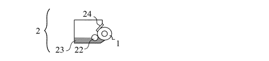
現像装置2は、静電潜像を担持する潜像担持体21と対向した状態でトナーを担持する現像ローラ1と、現像ローラ1に担持されたトナーを摩擦帯電しながら該トナーの層厚を規制する規制ブレード24とを備えている。現像装置2においては、現像ローラ1が潜像担持体21にトナー23を付与することにより静電潜像を現像してトナー像を形成する。
On the other hand, the untransferred toner remaining on the
The developing
図3に示された現像装置2は、一成分トナーとして非磁性のトナー23を収容した現像容器と、該現像容器内の長手方向に延在する開口部に位置するトナー担持体としての現像ローラ1(本発明の現像ローラ)を備えている。また、規制ブレード(塗布ブレード)24は、長手方向に延在する開口部の上縁に沿って配置されている。
The developing
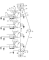
プロセスカートリッジの実施形態の一例の説明図を図4に示す。図4に示したプロセスカートリッジは、非磁性のトナー23を収容した現像容器と、トナー担持体としての現像ローラ1と、規制ブレード24とを備えている。プロセスカートリッジは、上記部材が一体的に保持されてなるものであり、電子写真装置の本体に着脱可能に設けられる。なお、画像形成時には、現像ローラ1は潜像担持体21と接触幅をもって接触している。
FIG. 4 is an explanatory diagram of an example of the embodiment of the process cartridge. The process cartridge shown in FIG. 4 includes a developing container containing
現像装置2においては、トナー塗布部材(RSローラ)22が、現像容器内で、トナーの層厚を規制する部材である規制ブレード24の現像ローラ1の表面との接触部に対し現像ローラ1の回転方向上流側に接触され、かつ、回転可能に支持されている。トナー塗布部材22の構造としては、発泡骨格状スポンジ構造や軸芯体上にレーヨン、ポリアミドの如き繊維を植毛したファーブラシ構造のものが、現像ローラ1へのトナー23の供給及び未現像トナーの剥ぎ取りの点から好ましい。
具体的には、軸芯体上にポリウレタンフォームを設けた直径16mmの弾性ローラをトナー塗布部材22として用いることができる。このトナー塗布部材22の現像ローラ1に対する接触幅としては、1mm以上8mm以下が好ましく、また、現像ローラ1に対してその接触部において相対速度をもたせることが好ましい。
In the developing
Specifically, an elastic roller having a diameter of 16 mm in which polyurethane foam is provided on the shaft core body can be used as the
プロセスカートリッジは、潜像担持体としての潜像担持体21と、潜像担持体21の表面を一様に帯電する帯電装置としての帯電部材26、クリーニング部材、転写ローラ31のうちの少なくとも一つを有しているものであってもよい。
図3に示すカラー電子写真装置では転写ベルト34が存在するために転写ローラ31を組み込んだプロセスカートリッジとすることはできないが、モノカラー電子写真装置では潜像担持体21等と一体としたプロセスカートリッジとすることが可能である。
The process cartridge includes at least one of a
In the color electrophotographic apparatus shown in FIG. 3, since the
以下に、実施例を示し、本発明をより具体的に説明する。
実施例、比較例に用いたシリカ、及び分布曲線における最多頻度値でのストークス相当径をDst(nm)、その形態、コロイド状シリカの場合はその質量%を、表2に示す。
Hereinafter, the present invention will be described more specifically with reference to examples.
Table 2 shows the silica used in Examples and Comparative Examples, the Stokes equivalent diameter at the most frequent value in the distribution curve, Dst (nm), its form, and the mass% in the case of colloidal silica.
その他の実施例、比較例に用いた材料は表4の通りである。 Table 4 shows materials used in other examples and comparative examples.
[実施例1]現像ローラ1
1.軸芯体の作製
軸芯体としてニッケル鍍金を施したSUS製の直径6mmの芯金の外周面に、さらにプライマー:「メタロックN−33」(商品名)を塗布し、温度150℃で10分間焼き付けしたものを準備した。
[Example 1] Developing
1. Preparation of shaft core body A primer: “Metallock N-33” (trade name) was further applied to the outer peripheral surface of a SUS 6 mm diameter metal core with nickel plating as the shaft core body, and the temperature was 150 ° C. for 10 minutes. A baked one was prepared.
2.弾性体層用混合物の調製
表5の5成分を、温度50℃に調節した密閉型ミキサーにて15分間混練して、原料混合物を調製した。
2. Preparation of mixture for elastic layer 5 ingredients in Table 5 were kneaded for 15 minutes in a closed mixer adjusted to a temperature of 50 ° C. to prepare a raw material mixture.
この原料混合物に対して、エピクロロヒドリンゴム(ECO)100質量部を基準として、表6の3成分を添加し、温度20℃に冷却した二本ロール機にて10分間混練して、第二層用混合物を得た。 To this raw material mixture, based on 100 parts by mass of epichlorohydrin rubber (ECO), the three components shown in Table 6 were added and kneaded for 10 minutes in a two-roll mill cooled to a temperature of 20 ° C. A layer mixture was obtained.
3.弾性ローラの作製
軸芯体の表面に、押出し機により、内側に弾性体層用混合物を円筒状で厚さ3.5mmとなるように押出して、外径13.0mmのローラ形状のサンプルを得た。これを温度150℃で40分間加硫した後、研削盤にて砥石研磨を行い、弾性体層が2.97mmで、外径が直径11.94mmの弾性ローラを作製した。
3. Production of an elastic roller A roller-shaped sample having an outer diameter of 13.0 mm is obtained by extruding the elastic layer mixture into a cylindrical shape with a thickness of 3.5 mm on the inner surface of the shaft core by an extruder. It was. This was vulcanized at a temperature of 150 ° C. for 40 minutes and then polished with a grinder to produce an elastic roller having an elastic layer of 2.97 mm and an outer diameter of 11.94 mm.
4.表面層用混合物1の調製
室温23℃±2℃にて、行った。
2Lのガラス製4つ口フラスコに、
・蒸留水 200gと
・コロイダルシリカ:スノーテックスXS(商品名、日産化学工業株式会社製)
1000g
を入れ、滴下ロート、還流冷却管、及び温度計を装着し、撹拌装置上にセットし、窒素気流下にて撹拌させ、目視にて均一な状態とした。
4). Preparation of
In a 2 L glass 4-neck flask,
・ Distilled water 200g ・ Colloidal silica: Snowtex XS (trade name, manufactured by Nissan Chemical Industries, Ltd.)
1000g
Were added, and a dropping funnel, a reflux condenser, and a thermometer were attached, set on a stirring device, stirred under a nitrogen stream, and brought into a uniform state visually.
撹拌したまま、滴下ロートにて、
・ノニオン界面活性剤:NE−10(旭電化工業株式会社製)5.0g
を添加した。
その後、
・硫酸(2規定)
を添加し、pH8〜8.5に調整し、その後、液温を70℃に昇温させた。
While stirring, with a dropping funnel,
-Nonionic surfactant: NE-10 (Asahi Denka Kogyo Co., Ltd.) 5.0 g
Was added.
after that,
・ Sulfuric acid (2 regulations)
Was adjusted to pH 8 to 8.5, and then the liquid temperature was raised to 70 ° C.
続いて、
・過硫酸アンモニウム 1.0g
を添加した。
続いて、アクリル系単量体として、
・メタクリル酸メチル(MMA) 60gと
・アクリル酸n−ブチル(n−BA) 140g
の混合物(均一に撹拌したもの)を用意し、
この混合物10gを、15分間かけて滴下し、その後60分間放置した。
continue,
・ Ammonium persulfate 1.0 g
Was added.
Subsequently, as an acrylic monomer,
・ Methyl methacrylate (MMA) 60g ・ Acrylic acid n-butyl (n-BA) 140g
Prepare a mixture of (mixed uniformly)
10 g of this mixture was added dropwise over 15 minutes and then left for 60 minutes.
続いて、
・ノニオン界面活性剤:エマルゲン840S(商品名、花王株式会社製) 3.0g
を加え、液温70℃で、残りの混合物190gを5時間かけて滴下し、滴下終了後、1時間撹拌を続けた。
この後、液温30℃以下まで自然冷却し、シリカをコアとし、界面活性剤が介在して、アクリル系単量体をシェルとするコア−シェル複合粒子の分散した表面層用水性分散体を得た。
continue,
Nonionic surfactant: Emulgen 840S (trade name, manufactured by Kao Corporation) 3.0 g
Was added dropwise at a liquid temperature of 70 ° C. over 5 hours, and stirring was continued for 1 hour after completion of the dropwise addition.
Thereafter, the aqueous dispersion for the surface layer in which the core-shell composite particles in which the liquid temperature is 30 ° C. or less, the silica is the core, the surfactant is interposed, and the acrylic monomer is the shell is dispersed. Obtained.
この水性分散体を2Lのガラス瓶に移し替え、
・カーボンブラック:トーカブラック#5500 40g
を添加し、メディアとしてガラスビーズ(平均粒径0.8mm)を400gを混合し、ペイントシェーカー分散機を用いて12時間分散して、ガラスビーズを取り除くことで、表面層用混合物1を得た。
Transfer this aqueous dispersion to a 2L glass bottle,
・ Carbon black: Talker Black # 5500 40g
, 400 g of glass beads (average particle size 0.8 mm) were mixed as a medium, dispersed for 12 hours using a paint shaker disperser, and the glass beads were removed, thereby obtaining a
5.現像ローラ1の作製
この塗料溶液(表面層用混合物1)中に、上記弾性ローラ1を浸漬してコーティングした後、引上げて乾燥させ、60℃にて30分間加熱処理することで、厚さ約30μmの表面層を弾性体層の外周に設けた現像ローラ1を作製した。
なお、表面層のシリカ粒子の分散状態を透過型電子顕微鏡(TEM)日立 H−800で観察したところ、平均粒子径5.2nmの粒子が個々に存在していることが確認され、良好な状態であった。
5. Production of developing
In addition, when the dispersion state of the silica particles in the surface layer was observed with a transmission electron microscope (TEM) Hitachi H-800, it was confirmed that particles having an average particle diameter of 5.2 nm were present individually, and the state was good. Met.
[実施例2]現像ローラ2
アクリル系単量体を下記とした以外は、実施例1と同様にして、現像ローラ2を作製した。
アクリル系単量体:
・メタクリル酸メチル 60g
・アクリル酸2−エチルヘキシル 140g
[Example 2] Developing
A developing
Acrylic monomer:
・ Methyl methacrylate 60g
・ 140g 2-ethylhexyl acrylate
[実施例3]現像ローラ3
コロイダルシリカを下記とした以外は、実施例1と同様にして、現像ローラ3を作製した。
・コロイダルシリカ:スノーテックスS(商品名) 667g
[実施例4]現像ローラ4
コロイダルシリカを下記とした以外は、実施例1と同様にして、現像ローラ4を作製した。
・コロイダルシリカ:スノーテックス40(商品名) 500g
[Example 3] Developing roller 3
A developing roller 3 was produced in the same manner as in Example 1 except that colloidal silica was changed as follows.
・ Colloidal silica: Snowtex S (trade name) 667g
[Embodiment 4] Developing roller 4
A developing roller 4 was produced in the same manner as in Example 1 except that colloidal silica was changed as follows.
・ Colloidal silica: Snowtex 40 (trade name) 500g
[実施例5]現像ローラ5
コロイダルシリカを下記とした以外は、実施例1と同様にして、現像ローラ5を作製した。
・コロイダルシリカ:スノーテックス50(商品名) 250g
[実施例6]現像ローラ6
コロイダルシリカを下記とした以外は、実施例1と同様にして、現像ローラ6を作製した。
・コロイダルシリカ:スノーテックス50(商品名) 417g
[Embodiment 5] Developing roller 5
A developing roller 5 was produced in the same manner as in Example 1 except that colloidal silica was changed as follows.
・ Colloidal silica: Snowtex 50 (trade name) 250g
[Embodiment 6] Developing roller 6
A developing roller 6 was produced in the same manner as in Example 1 except that colloidal silica was changed as follows.
・ Colloidal silica: Snowtex 50 (trade name) 417g
[実施例7]現像ローラ7
コロイダルシリカを下記とした以外は、実施例1と同様にして、現像ローラ7を作製した。
・コロイダルシリカ:スノーテックス50(商品名) 583g
[実施例8]現像ローラ8
アクリル系単量体を下記とした以外は、実施例6と同様にして、現像ローラ8を作製した。
アクリル系単量体:
・メタクリル酸メチル 60g
・アクリル酸2−エチルヘキシル 140g
[Embodiment 7] Developing roller 7
A developing roller 7 was produced in the same manner as in Example 1 except that colloidal silica was changed as follows.
・ Colloidal silica: Snowtex 50 (trade name) 583g
[Eighth Embodiment] Developing Roller 8
A developing roller 8 was produced in the same manner as in Example 6 except that the acrylic monomer was as follows.
Acrylic monomer:
・ Methyl methacrylate 60g
・ 140g 2-ethylhexyl acrylate
[実施例9]現像ローラ9
アクリル系単量体を下記とした以外は、実施例1と同様にして、現像ローラ9を作製した。
アクリル系単量体:
・メタクリル酸メチル 60g
・アクリル酸2−エチルヘキシル 100g
・スチレン 40g
[Embodiment 9] Developing roller 9
A developing roller 9 was produced in the same manner as in Example 1 except that the acrylic monomer was as follows.
Acrylic monomer:
・ Methyl methacrylate 60g
・ 2-ethylhexyl acrylate 100g
・ Styrene 40g
[実施例10]現像ローラ10
アクリル系単量体を下記とした以外は、実施例1と同様にして、現像ローラ10を作製した。
アクリル系単量体:
・アクリル酸n−ブチル(n−BA) 100g
・アクリル酸2−エチルヘキシル 100g
[Embodiment 10] Developing roller 10
A developing roller 10 was produced in the same manner as in Example 1 except that the acrylic monomer was as follows.
Acrylic monomer:
・ 100 g of n-butyl acrylate (n-BA)
・ 2-ethylhexyl acrylate 100g
[実施例11]現像ローラ11
コロイダルシリカを下記とした以外は、実施例1と同様にして、現像ローラ11を作製した。
・コロイダルシリカ:スノーテックス20L(商品名) 1000g
[実施例12]現像ローラ12
コロイダルシリカを下記とした以外は、実施例1と同様にして、現像ローラ12を作製した。
・コロイダルシリカ:スノーテックスXL(商品名) 500g
[Embodiment 11] Developing
A developing
・ Colloidal silica: Snowtex 20L (trade name) 1000g
[Embodiment 12] Developing
A developing
・ Colloidal silica: Snowtex XL (trade name) 500g
[実施例13]現像ローラ13
コロイダルシリカを下記とした以外は、実施例1と同様にして、現像ローラ13を作製した。
・コロイダルシリカ:スノーテックスZL(商品名) 500g
[実施例14]現像ローラ14
コロイダルシリカを下記とした以外は、実施例8と同様にして、現像ローラ14を作製した。
・コロイダルシリカ:スノーテックスZL(商品名) 500g
[Embodiment 13] Developing
A developing
・ Colloidal silica: Snowtex ZL (trade name) 500g
[Embodiment 14] Developing roller 14
A developing roller 14 was produced in the same manner as in Example 8 except that colloidal silica was changed as follows.
・ Colloidal silica: Snowtex ZL (trade name) 500g
[実施例15]現像ローラ15
コロイダルシリカを下記とした以外は、実施例9と同様にして、現像ローラ15を作製した。
・コロイダルシリカ:スノーテックスZL(商品名) 500g
[実施例16]現像ローラ16
コロイダルシリカを下記とした以外は、実施例1と同様にして、現像ローラ16を作製した。
・コロイダルシリカ:アデライトAT−40(商品名) 500g
[Embodiment 15] Developing roller 15
A developing roller 15 was produced in the same manner as in Example 9 except that colloidal silica was changed as follows.
・ Colloidal silica: Snowtex ZL (trade name) 500g
[Embodiment 16] Developing roller 16
A developing roller 16 was produced in the same manner as in Example 1 except that colloidal silica was changed as follows.
・ Colloidal silica: Adelite AT-40 (trade name) 500 g
[実施例17]現像ローラ17
弾性体層用混合物の調製を下記とした以外は、実施例6と同様にして、現像ローラ17を作製した。
2.弾性体層用混合物の調製
表7の6成分を、温度50℃に調節した密閉型ミキサーにて10分間混練して、原料混合物を調製した。
[Embodiment 17] Developing roller 17
A developing roller 17 was produced in the same manner as in Example 6 except that the elastic layer mixture was prepared as follows.
2. Preparation of mixture for elastic layer 6 components in Table 7 were kneaded for 10 minutes in a closed mixer adjusted to a temperature of 50 ° C. to prepare a raw material mixture.
この原料混合物に対して、NBR100質量部基準で、表8の4成分を添加し、温度20℃に冷却した二本ロール機にて8分間混練して、弾性体層用混合物を得た。 Four ingredients in Table 8 were added to this raw material mixture on the basis of 100 parts by mass of NBR, and kneaded for 8 minutes in a two-roll machine cooled to a temperature of 20 ° C. to obtain an elastic layer mixture.
[実施例18]現像ローラ18
アクリル系単量体、コロイダルシリカを下記とした以外は、実施例17と同様にして、現像ローラ18を作製した。
アクリル系単量体:
・メタクリル酸メチル 60g
・アクリル酸2−エチルヘキシル 100g
・スチレン 40g
コロイダルシリカ:
・スノーテックスXL(商品名) 500g
[Embodiment 18] Developing roller 18
A developing roller 18 was produced in the same manner as in Example 17 except that the acrylic monomer and colloidal silica were changed as follows.
Acrylic monomer:
・ Methyl methacrylate 60g
・ 2-ethylhexyl acrylate 100g
・ Styrene 40g
Colloidal silica:
・ Snowtex XL (trade name) 500g
[実施例19]現像ローラ19
弾性体層用混合物の調製を下記とした以外は、実施例6と同様にして、現像ローラ19を作製した。
2.弾性体層用混合物の調製
表9の6成分を、温度50℃に調節した密閉型ミキサーにて10分間混練して、原料混合物を調製した。
[Embodiment 19] Developing roller 19
A developing roller 19 was produced in the same manner as in Example 6 except that the elastic layer mixture was prepared as follows.
2. Preparation of mixture for elastic layer 6 components in Table 9 were kneaded for 10 minutes in a closed mixer adjusted to a temperature of 50 ° C. to prepare a raw material mixture.
この原料混合物に対して、EPDM100質量部基準で、表10の5成分を添加し、温度20℃に冷却した二本ロール機にて10分間混練して、第一層用混合物を得た。 5 ingredients of Table 10 were added with respect to 100 mass parts of EPDM with respect to this raw material mixture, and it knead | mixed for 10 minutes with the double roll machine cooled to the temperature of 20 degreeC, and obtained the mixture for 1st layers.
[実施例20]現像ローラ20
アクリル系単量体、コロイダルシリカを下記とした以外は、実施例19と同様にして、現像ローラ20を作製した。
[Embodiment 20] Developing roller 20
A developing roller 20 was produced in the same manner as in Example 19 except that the acrylic monomer and colloidal silica were changed as follows.
アクリル系単量体:
・メタクリル酸メチル 60g
・アクリル酸2−エチルヘキシル 140g
コロイダルシリカ:
・スノーテックスS(商品名) 667g
Acrylic monomer:
・ Methyl methacrylate 60g
・ 140g 2-ethylhexyl acrylate
Colloidal silica:
・ Snowtex S (trade name) 667g
[実施例21]現像ローラ21
コロイダルシリカを下記とした以外は、実施例1と同様にして、現像ローラ21を作製した。
・コロイダルシリカ:MP−2040(商品名) 500g
[Example 21] Developing
A developing
・ Colloidal silica: MP-2040 (trade name) 500 g
[実施例22]現像ローラ22
コロイダルシリカを下記とした以外は、実施例1と同様にして、現像ローラ22を作製した。
・コロイダルシリカ:MP−4540M(商品名) 500g
[実施例23]現像ローラ23
表面層用混合物に用いたカーボンブラックを下記とした以外は、実施例6と同様にして、現像ローラ23を作製した。
・カーボンブラック:トーカブラック#4500(商品名) 50g
[Embodiment 22] Developing
A developing
・ Colloidal silica: MP-4540M (trade name) 500 g
[Example 23] Developing
A developing
・ Carbon black: Talker Black # 4500 (trade name) 50g
[実施例24]現像ローラ24
表面層用混合物に用いたカーボンブラックを下記とした以外は、実施例6と同様にして、現像ローラ24を作製した。
・カーボンブラック:トーカブラック#7360SB(商品名) 80g
[実施例25]現像ローラ25
表面層用混合物に用いたカーボンブラックを下記とした以外は、実施例6と同様にして、現像ローラ25を作製した。
・カーボンブラック:トーカブラック#8300F(商品名) 35g
[Embodiment 24] Developing
A developing
・ Carbon black: Talker Black # 7360SB (trade name) 80g
[Embodiment 25] Developing
A developing
・ Carbon black: Toka Black # 8300F (trade name) 35g
[実施例26]現像ローラ26
表面層用混合物に用いたカーボンブラックを下記とした以外は、実施例6と同様にして、現像ローラ26を作製した。
・カーボンブラック:MONARCH1300(商品名) 30g
[実施例27]現像ローラ27
表面層用混合物に用いたカーボンブラックを下記とした以外は、実施例6と同様にして、現像ローラ27を作製した。
・カーボンブラック:ケッチェンブラックECP600(商品名) 20g
[Embodiment 26] Developing
A developing
・ Carbon black: MONARCH1300 (trade name) 30g
[Embodiment 27] Developing
A developing
・ Carbon black: Ketjen Black ECP600 (trade name) 20g
[実施例28]現像ローラ28
表面層用混合物に用いたカーボンブラックを下記とした以外は、実施例8と同様にして、現像ローラ28を作製した。
・カーボンブラック:トーカブラック#7360SB(商品名) 80g
[実施例29]現像ローラ29
表面層用混合物に用いたカーボンブラックを下記とした以外は、実施例8と同様にして、現像ローラ29を作製した。
・カーボンブラック:Printex60(商品名) 65g
[Embodiment 28] Developing
A developing
・ Carbon black: Talker Black # 7360SB (trade name) 80g
[Example 29] Developing
A developing
・ Carbon black: Printex 60 (trade name) 65g
[実施例30]現像ローラ30
表面層用混合物に用いたコロイダルシリカ、カーボンブラックを下記とした以外は、実施例9と同様にして、現像ローラ30を作製した。
・コロイダルシリカ:アデライトAT−40(商品名) 500g
・カーボンブラック:Printex60(商品名) 65g
[Embodiment 30] Developing
A developing
・ Colloidal silica: Adelite AT-40 (trade name) 500 g
・ Carbon black: Printex 60 (trade name) 65g
[実施例31]現像ローラ31
表面層用混合物に用いたカーボンブラックに代えて、下記カーボンブラック分散ペーストを用いた以外は、実施例6と同様にして、現像ローラ31を作製した。
・ライオンペースト311N(商品名) 120g
[実施例32]現像ローラ32
表面層用混合物に用いたカーボンブラックに代えて、下記カーボンブラック分散ペーストを用いた以外は、実施例15と同様にして、現像ローラ32を作製した。
・ライオンペースト311N(商品名) 120g
[Example 31] Developing
A developing
・ Lion paste 311N (trade name) 120g
[Embodiment 32] Developing
A developing
・ Lion paste 311N (trade name) 120g
〔比較例1〕現像ローラ33
弾性ローラは、実施例1と同じものを用意した。
1.表面層用混合物2の調製
表11の3成分を、メチルエチルケトンを主とする溶剤を用いて、十分に撹拌して、均一な固形分18%の有機溶剤混合溶液(表面層用混合物2)を調製した。
[Comparative Example 1] Developing
The same elastic roller as that in Example 1 was prepared.
1. Preparation of
2.現像ローラの作製
表面層用混合物2の溶液中に、上記弾性ローラを浸漬し、引上げてコーティングした後、乾燥させ、温度145℃にて1時間加熱処理することで、厚さ約30μmの表面層を弾性体層の外周に設けた現像ローラ33を作製した。
2. Production of developing roller The elastic roller is dipped in the solution of the
〔比較例2〕現像ローラ34
表面層用混合物1に下記を追加した以外は、比較例1と同様にして、現像ローラ34を作製した。
・シリカ:「AEROSIL300」 80質量部。
[Comparative Example 2] Developing
A developing
Silica: “AEROSIL300” 80 parts by mass.
〔比較例3〕現像ローラ35
弾性ローラは、実施例1と同じものを用意した。
2.表面層用混合物3の調製
表12の4成分を、メチルエチルケトンを主とする溶剤を用いて、十分に撹拌して、均一な固形分25%の有機溶剤混合溶液(表面層用混合物3)を調製した。
[Comparative Example 3] Developing
The same elastic roller as that in Example 1 was prepared.
2. Preparation of surface layer mixture 3 The four components in Table 12 were sufficiently stirred using a solvent mainly composed of methyl ethyl ketone to prepare a uniform organic solvent mixed solution (surface layer mixture 3) having a solid content of 25%. did.
3.現像ローラの作製
表面層用混合物3の溶液中に、上記弾性ローラを浸漬し、引上げてコーティングした後、乾燥させ、温度140℃にて4時間加熱処理することで、厚さ約20μmの表面層を弾性体層の外周に設けた現像ローラ35を作製した。
3. Production of developing roller The elastic roller is dipped in the solution of the surface layer mixture 3, pulled up, coated, dried, and heat-treated at a temperature of 140 ° C. for 4 hours to obtain a surface layer having a thickness of about 20 μm. A developing
〔比較例4〕現像ローラ36
実施例1の表面層用混合物1においてコロイダルシリカをコアに使用しなかった以外は、実施例1と同様にして、現像ローラ36を作製した。
〔比較例5〕現像ローラ37
実施例2の表面層用混合物1においてコロイダルシリカをコアに使用しなかった以外は、実施例2と同様にして、現像ローラ37を作製した。
[Comparative Example 4] Developing
A developing
[Comparative Example 5] Developing
A developing
<評価方法>
次に、現像ローラの特性値の測定方法、評価方法について説明する。
電子写真装置として、カラーレーザービームプリンター「HP Color LaserJet CP3525dn」(商品名、日本ヒューレット・パッカード株式会社製)を用意した。このカラーレーザービームプリンターは、シアン、マゼンタ、イエロー及びブラックのカラーカートリッジを備え、各カートリッジに対し、画像書き込み手段(レーザービーム)が設けられ、転写ベルトを備えたタンデム型である。尚、標準の画像作成能力はA4サイズで30枚/分である。
<Evaluation method>
Next, a method for measuring and evaluating a characteristic value of the developing roller will be described.
As an electrophotographic apparatus, a color laser beam printer “HP Color LaserJet CP3525dn” (trade name, manufactured by Hewlett-Packard Japan Ltd.) was prepared. This color laser beam printer is a tandem type printer that includes cyan, magenta, yellow, and black color cartridges, each of which is provided with image writing means (laser beam) and a transfer belt. The standard image creation capability is 30 sheets / minute for A4 size.
上記カラーカートリッジは、潜像担持体、帯電ローラ、現像ローラ、トナー供給ローラ規制ブレードが設けられ(一成分接触現像方式対応)、現像ローラは潜像担持体に当接して配置されている。さらに、前記カラーカートリッジには、潜像担持体に当接して、クリーニングブレードが設けられている。上記カラーレーザービームプリンターは、帯電ローラによる帯電前に潜像担持体上に残る帯電を除去するための前露光手段を備えている。 The color cartridge is provided with a latent image carrier, a charging roller, a developing roller, and a toner supply roller regulating blade (corresponding to a one-component contact development system), and the developing roller is disposed in contact with the latent image carrier. Further, the color cartridge is provided with a cleaning blade in contact with the latent image carrier. The color laser beam printer includes pre-exposure means for removing the charge remaining on the latent image carrier before charging by the charging roller.
シアンカラーカートリッジの現像ローラとして、前記の現像ローラ1〜50をそれぞれ組み込んだ。また、マゼンタ、イエローおよびブラックの各カラーカートリッジは、トナーを抜き取り、さらにトナー残量検知機構を無効として、それぞれのステーションに配置した。
上記各カラーカートリッジをカラーレーザービームプリンターに装着し、温度10℃±2℃、相対湿度50%±5%の環境下で、画像領域全体が一様であるベタ画像を、11枚め、2001枚め、4001枚め、6001枚めに各1枚、印刷した。また、全面ハーフトーン画像を12枚め、2002枚めに各1枚を印刷した。転写材としては、A4サイズの普通紙「セレクトペーパー SC−250 A4」(商品名、キヤノン株式会社製)を用いた。
The developing
The above color cartridges are mounted on a color laser beam printer, and the 11th and 2001th solid images with the entire image area are uniform in an environment of temperature 10 ° C. ± 2 ° C. and relative humidity 50% ± 5%. For this reason, one sheet was printed on each of the 4001st sheet and the 6001st sheet. In addition, the entire halftone image was printed on the 12th sheet and one sheet was printed on the 2002th sheet. As the transfer material, A4-sized plain paper “Select Paper SC-250 A4” (trade name, manufactured by Canon Inc.) was used.
[初期における濃度均一性の評価]
11枚目、12枚目に出力したベタ画像、全面ハーフトーン画像に関し、その画像の濃度均一性に着目して、表13の基準で評価した。
[Evaluation of initial density uniformity]
The solid images and full-face halftone images output on the 11th and 12th images were evaluated according to the criteria shown in Table 13, focusing on the density uniformity of the images.
[経時における濃度均一性の評価]
2001枚め、2002枚めに出力したベタ画像、全面ハーフトーン画像に関し、その画像の濃度均一性に着目して、表14の基準で評価した。
[Evaluation of concentration uniformity over time]
With respect to the solid images and full-surface halftone images output on the 2001th and 2002th sheets, the evaluation was made according to the criteria shown in Table 14, focusing on the density uniformity of the images.
[耐フィルミング性の評価]
2001枚め、4001枚め、6001枚めに出力したベタ画像に関し、画像印字方向と同じ方向にスジ状の濃淡ムラを縦スジ(フィルミング発生時の問題画像)とし、その有無を目視により観察し、表15の基準で評価した。
[Evaluation of filming resistance]
For solid images output on the 2001th, 4001st, and 6001st sheets, streak-like shading unevenness in the same direction as the image printing direction is regarded as a vertical streak (problem image when filming occurs), and the presence or absence is observed visually. And evaluated according to the criteria in Table 15.
現像ローラ1〜37について、上記評価の結果を、表16に示す。
Table 16 shows the evaluation results of the developing
実施例1〜32は、いずれも、濃度均一性は、初期Aランク、経時でBランク以内、耐フィルミング性は、2001枚めではAランク、4001枚め、6001枚め共にBランク以内となった。すなわち、現像剤に対する帯電付与性と、現像剤付着等を抑制する性能(耐フィルミング性)を高次元で合わせ持つ現像ローラであった。その中でも、実施例4、6、8〜12、16〜19、25、27、29〜31は、評価項目が全てAランクとなり、極めて良好な結果であった。 In each of Examples 1 to 32, the density uniformity is within the A rank for the initial A and within the B rank over time, and the filming resistance is within the B rank for the 2001th sheet, the A rank, the 4001st sheet, and the 6001st sheet. became. That is, the developing roller has a high level of charge imparting property to the developer and performance (filming resistance) for suppressing the adhesion of the developer. Among them, Examples 4, 6, 8 to 12, 16 to 19, 25, 27, and 29 to 31 were all excellent evaluation results because the evaluation items were all ranked A.
1‥‥現像ローラ
11‥軸芯体
12‥弾性体層
13‥表面層
DESCRIPTION OF
Claims (7)
該表面層は、アクリル樹脂のマトリクス中にシリカ粒子が分散してなるナノコンポジット構造を有することを特徴とする現像ローラ。 A developing roller having a shaft core and a surface layer,
The developing roller, wherein the surface layer has a nanocomposite structure in which silica particles are dispersed in an acrylic resin matrix.
該カーボンブラックのCTAB吸着比表面積が60m2/g以上220m2/g以下である請求項1または2に記載の現像ローラ。 The surface layer contains carbon black;
The developing roller according to claim 1, wherein the carbon black has a CTAB adsorption specific surface area of 60 m 2 / g or more and 220 m 2 / g or less.
シリカ粒子のコアと、アクリル樹脂を含むシェルとを有するコア−シェル構造を有する粒子を水性媒体に分散させてなる水性分散体の被膜を乾燥せしめて該表面層を形成する工程を有することを特徴する現像ローラの製造方法。 A method for producing a developing roller having a shaft core and a surface layer,
A step of forming a surface layer by drying a coating film of an aqueous dispersion obtained by dispersing particles having a core-shell structure having a core of silica particles and a shell containing an acrylic resin in an aqueous medium. A developing roller manufacturing method.
Priority Applications (1)
| Application Number | Priority Date | Filing Date | Title |
|---|---|---|---|
| JP2013254503A JP2015114392A (en) | 2013-12-09 | 2013-12-09 | Developing roller, developing roller manufacturing method, process cartridge, and electrophotographic apparatus |
Applications Claiming Priority (1)
| Application Number | Priority Date | Filing Date | Title |
|---|---|---|---|
| JP2013254503A JP2015114392A (en) | 2013-12-09 | 2013-12-09 | Developing roller, developing roller manufacturing method, process cartridge, and electrophotographic apparatus |
Publications (1)
| Publication Number | Publication Date |
|---|---|
| JP2015114392A true JP2015114392A (en) | 2015-06-22 |
Family
ID=53528260
Family Applications (1)
| Application Number | Title | Priority Date | Filing Date |
|---|---|---|---|
| JP2013254503A Pending JP2015114392A (en) | 2013-12-09 | 2013-12-09 | Developing roller, developing roller manufacturing method, process cartridge, and electrophotographic apparatus |
Country Status (1)
| Country | Link |
|---|---|
| JP (1) | JP2015114392A (en) |
Cited By (3)
| Publication number | Priority date | Publication date | Assignee | Title |
|---|---|---|---|---|
| WO2019150763A1 (en) * | 2018-01-30 | 2019-08-08 | 株式会社ブリヂストン | Electroconductive roller and image formation device |
| CN112596355A (en) * | 2019-10-02 | 2021-04-02 | 株式会社普利司通 | Charging roller |
| US10969709B2 (en) | 2018-04-20 | 2021-04-06 | Canon Kabushiki Kaisha | Member for electrophotography, process cartridge and electrophotographic apparatus |
-
2013
- 2013-12-09 JP JP2013254503A patent/JP2015114392A/en active Pending
Cited By (4)
| Publication number | Priority date | Publication date | Assignee | Title |
|---|---|---|---|---|
| WO2019150763A1 (en) * | 2018-01-30 | 2019-08-08 | 株式会社ブリヂストン | Electroconductive roller and image formation device |
| US10969709B2 (en) | 2018-04-20 | 2021-04-06 | Canon Kabushiki Kaisha | Member for electrophotography, process cartridge and electrophotographic apparatus |
| CN112596355A (en) * | 2019-10-02 | 2021-04-02 | 株式会社普利司通 | Charging roller |
| US11314180B2 (en) | 2019-10-02 | 2022-04-26 | Bridgestone Corporation | Charging roller |
Similar Documents
| Publication | Publication Date | Title |
|---|---|---|
| JP5021354B2 (en) | Rubber member and developing roller comprising the rubber member | |
| JP5081292B2 (en) | Transfer member | |
| JP5188681B2 (en) | Semiconductive rubber member and developing roller comprising the rubber member | |
| JP4498985B2 (en) | Conductive rubber roller | |
| JP5835973B2 (en) | Developing member, electrophotographic process cartridge, and electrophotographic image forming apparatus | |
| US9014590B2 (en) | Cleaning member, charging device assembly, and image forming apparatus | |
| KR20080042757A (en) | Foam rubber roller | |
| JP6109117B2 (en) | Semiconductive roller and method for manufacturing the same | |
| JP6275586B2 (en) | Conductive roller, manufacturing method thereof, and image forming apparatus | |
| JP5160728B2 (en) | Semiconductive rubber member for electrophotography | |
| CN100468219C (en) | Imaging device and cleaning method thereof | |
| JP6323955B2 (en) | Semi-conductive roller | |
| JP2015114392A (en) | Developing roller, developing roller manufacturing method, process cartridge, and electrophotographic apparatus | |
| CN100492207C (en) | semi-conductive roller | |
| JP5073241B2 (en) | Semiconductive roll | |
| CN103576501A (en) | Developing roller | |
| JP5623211B2 (en) | Developing roller, developing method, process cartridge, and image forming apparatus | |
| JP5058691B2 (en) | Electrophotographic charging member, process cartridge, and electrophotographic apparatus | |
| JP2005049852A (en) | Conductive rubber roller | |
| JP5247418B2 (en) | Developing roller, electrophotographic process cartridge, and image forming apparatus | |
| JP2016206457A (en) | Semiconductive roller | |
| JP5280689B2 (en) | Rubber roll and rubber roll manufacturing method | |
| JP5641794B2 (en) | Toner transport roller and manufacturing method thereof | |
| JP5160726B2 (en) | Conductive rubber roller | |
| KR100854664B1 (en) | Semi-conductive roller |