JP2015114369A - Projection device - Google Patents
Projection device Download PDFInfo
- Publication number
- JP2015114369A JP2015114369A JP2013254144A JP2013254144A JP2015114369A JP 2015114369 A JP2015114369 A JP 2015114369A JP 2013254144 A JP2013254144 A JP 2013254144A JP 2013254144 A JP2013254144 A JP 2013254144A JP 2015114369 A JP2015114369 A JP 2015114369A
- Authority
- JP
- Japan
- Prior art keywords
- light source
- heat
- heat radiating
- radiating portion
- projection apparatus
- Prior art date
- Legal status (The legal status is an assumption and is not a legal conclusion. Google has not performed a legal analysis and makes no representation as to the accuracy of the status listed.)
- Pending
Links
Images
Classifications
-
- G—PHYSICS
- G03—PHOTOGRAPHY; CINEMATOGRAPHY; ANALOGOUS TECHNIQUES USING WAVES OTHER THAN OPTICAL WAVES; ELECTROGRAPHY; HOLOGRAPHY
- G03B—APPARATUS OR ARRANGEMENTS FOR TAKING PHOTOGRAPHS OR FOR PROJECTING OR VIEWING THEM; APPARATUS OR ARRANGEMENTS EMPLOYING ANALOGOUS TECHNIQUES USING WAVES OTHER THAN OPTICAL WAVES; ACCESSORIES THEREFOR
- G03B21/00—Projectors or projection-type viewers; Accessories therefor
- G03B21/14—Details
- G03B21/16—Cooling; Preventing overheating
-
- G—PHYSICS
- G03—PHOTOGRAPHY; CINEMATOGRAPHY; ANALOGOUS TECHNIQUES USING WAVES OTHER THAN OPTICAL WAVES; ELECTROGRAPHY; HOLOGRAPHY
- G03B—APPARATUS OR ARRANGEMENTS FOR TAKING PHOTOGRAPHS OR FOR PROJECTING OR VIEWING THEM; APPARATUS OR ARRANGEMENTS EMPLOYING ANALOGOUS TECHNIQUES USING WAVES OTHER THAN OPTICAL WAVES; ACCESSORIES THEREFOR
- G03B21/00—Projectors or projection-type viewers; Accessories therefor
- G03B21/14—Details
- G03B21/20—Lamp housings
- G03B21/2006—Lamp housings characterised by the light source
- G03B21/2013—Plural light sources
-
- H—ELECTRICITY
- H04—ELECTRIC COMMUNICATION TECHNIQUE
- H04N—PICTORIAL COMMUNICATION, e.g. TELEVISION
- H04N9/00—Details of colour television systems
- H04N9/12—Picture reproducers
- H04N9/31—Projection devices for colour picture display, e.g. using electronic spatial light modulators [ESLM]
- H04N9/3141—Constructional details thereof
- H04N9/3144—Cooling systems
Landscapes
- Physics & Mathematics (AREA)
- General Physics & Mathematics (AREA)
- Engineering & Computer Science (AREA)
- Multimedia (AREA)
- Signal Processing (AREA)
- Projection Apparatus (AREA)
- Transforming Electric Information Into Light Information (AREA)
- Cooling Or The Like Of Electrical Apparatus (AREA)
Abstract
Description
本発明は、投影装置に関する。 The present invention relates to a projection apparatus.
例えばプロジェクタ装置などの投影装置においては、複数の光源が搭載されており、それぞれの光源に対してヒートシンクなどの放熱部が設けられている。各放熱部は、それぞれ専用のファンによって直接冷却されたり、一つのファンとダクトで連結され、当該一つのファンによって冷却されたりする場合がある(例えば特許文献1参照)。 For example, in a projection apparatus such as a projector apparatus, a plurality of light sources are mounted, and a heat radiating unit such as a heat sink is provided for each light source. Each heat radiating section may be directly cooled by a dedicated fan, or may be connected to one fan by a duct and cooled by the one fan (see, for example, Patent Document 1).
しかしながら、各放熱部にそれぞれ専用のファンを設けた場合や、各放熱部と一つのファンとをダクトで連結した場合のいずれにおいても、それだけ設置スペースを確保しなければならず、装置全体が大きくなってしまうのが実状である。
このため、本発明の課題は、光源に対する放熱構造をコンパクトにし、投影装置全体としての小型化を図ることである。
However, in each case where a dedicated fan is provided for each heat radiating part, or when each heat radiating part and one fan are connected by a duct, it is necessary to secure a sufficient installation space, which makes the entire apparatus large. The actual situation is.
Therefore, an object of the present invention is to make the heat dissipation structure for the light source compact and to reduce the size of the projection apparatus as a whole.
以上の課題を解決するため、本発明の一の態様によれば、
一の側面に吸気口が形成され、他の側面に排気口が形成された筐体と、
第一光源と、
複数のフィンを有する第一放熱部と、
前記第一光源と前記第一放熱部とを連結する第一伝熱管と、
第二光源と、
複数のフィンを有する第二放熱部と、
前記第二光源と前記第二放熱部とを連結する第二伝熱管と、を備え、
前記第一光源、前記第一放熱部、前記第一伝熱管、前記第一放熱部及び前記第二放熱部は、前記筐体内に収納されており、
前記吸気口から前記排気口を略直線状に結ぶ気体の流路上に前記第一放熱部及び前記第二放熱部が配置されていることを特徴とする投影装置が提供される。
In order to solve the above problems, according to one aspect of the present invention,
A housing having an air inlet on one side and an air outlet on the other side;
A first light source;
A first heat dissipating part having a plurality of fins;
A first heat transfer tube connecting the first light source and the first heat radiation part;
A second light source;
A second heat dissipating part having a plurality of fins;
A second heat transfer tube connecting the second light source and the second heat radiating section,
The first light source, the first heat radiating portion, the first heat transfer tube, the first heat radiating portion, and the second heat radiating portion are housed in the housing,
A projection device is provided, wherein the first heat radiating portion and the second heat radiating portion are disposed on a gas flow path that connects the air inlet to the air outlet in a substantially straight line.
本発明によれば、光源に対する放熱構造をコンパクトにすることができ、投影装置全体を小型化することが可能となる。 According to the present invention, the heat dissipation structure for the light source can be made compact, and the entire projection apparatus can be miniaturized.
以下に、本発明について、図面を用いて具体的な態様を説明する。ただし、発明の範囲は、図示例に限定されない。 Hereinafter, specific embodiments of the present invention will be described with reference to the drawings. However, the scope of the invention is not limited to the illustrated examples.
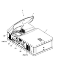
図1は投影装置1の概略構成を示す斜視図である。図1に示すように、投影装置1には、筐体2と、筐体2に対して開閉自在に取り付けられた蓋部材3とが設けられている。
FIG. 1 is a perspective view showing a schematic configuration of the
筐体2は、略直方体状に形成されていて、その内部に映像光を生成する複数の光源である赤色光源31,青色光源41及び緑色光源61(図2参照)、表示素子71(図2参照)及び光学系などを収納している。筐体2の上面の一部は開放していて、その内部には平面反射ミラー21が設けられている。また、筐体2の一側面には、蓋部材3の開閉用スイッチ22と、フォーカス調整用のフォーカスリング23と、電源スイッチ24と、が備えられている。また、筐体2の側面における複数の位置には、通気口25が設けられている。
The housing 2 is formed in a substantially rectangular parallelepiped shape, and a
蓋部材3は、筐体2の角部に対して回転自在に取り付けられている。蓋部材3の内面には、光学系から照射された映像光を平面反射ミラー21に向けて反射する自由曲面ミラー30が設けられている。
The
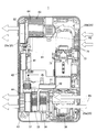
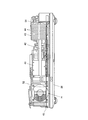
図2は投影装置1の内部構造を示す上面図である。図3は投影装置1の内部構造を示す側面図である。
筐体2の内部には、各種電子部品や光学部品が密に内蔵されている。ここで、図3に示すように、各種電子部品が実装された基板40は、筐体2の底板26に対して空間Hを空けて配置されており、この空間H内に空気等の気体が流れるようになっている。
FIG. 2 is a top view showing the internal structure of the
Various electronic components and optical components are densely embedded in the housing 2. Here, as shown in FIG. 3, the
また、図2に示すように、筐体2の一の側面における両端部には、それぞれ通気口25が形成されている。以下、この二つの通気口25を第一吸気口25a及び第二吸気口25bと称す。
そして、筐体2の前記一の側面に対向する他の側面の両端部には、それぞれ通気口25が形成されている。以下、この二つの通気口25を第一排気口25d及び第二排気口25eと称す。
図2に示すように、第一吸気口25a及び第一排気口25dが、筐体2の一端部側で対向するように配置されている。また、第二吸気口25b及び第二排気口25eが、筐体2の他端部側で対向するように配置されている。
In addition, as shown in FIG. 2,
And the
As shown in FIG. 2, the
[第一放熱構造]
まず、筐体2内における第一放熱構造について説明する。
第一吸気口25aから第一排気口25dを略直線状に結ぶ気体の流路R1近傍には、本発明に係る第一光源としての赤色光源31と、本発明に係る第二光源としての青色光源41とが配置されている。具体的には、赤色光源31は流路R1の中間付近に配置されていて、青色光源41は、第一排気口25d及び第二排気口25eが設けられた側面の中央付近に配置されている。
[First heat dissipation structure]
First, the first heat dissipation structure in the housing 2 will be described.
A
赤色光源31には、例えばヒートパイプなどからなる第一伝熱管32が連結されている。また、第一伝熱管32は折り曲げられていて、その折り曲げた先には第一放熱部33が連結されている。第一放熱部33には、複数のフィン34が設けられている。各フィン34の隙間は流路R1に沿って形成されている。
赤色光源31から発せられた熱は、第一伝熱管32によって第一放熱部33に伝導し、当該第一放熱部33によって放熱される。
A first
The heat generated from the
青色光源41には、例えばヒートパイプなどからなる第二伝熱管42が連結されている。また、第二伝熱管42の他端部には第二放熱部43が連結されている。第二放熱部43には、複数のフィン44が設けられている。各フィン44の隙間は流路R1に沿って形成されている。
青色光源41から発せられた熱は、第二伝熱管42によって第二放熱部43に伝導し、当該第二放熱部43によって放熱される。
The
The heat generated from the
ここで、赤色光源31は温度が上昇すると暗くなってしまうという性質がある。これに対し、青色光源41は温度にほぼ影響なく明るさが一定であるという性質がある。このため、赤色光源31は冷却すればするほど光源出力が上昇するので、第二放熱部43よりも先に第一放熱部33に対して、第一吸気口25aから吸気された気体が当たるように配置されている。つまり、赤色光源31が青色光源よりも温度低下による光源出力の増加量が大きいため、第一放熱部33が第二放熱部43よりも流路R1の上流側に配置されている。
さらに、赤色光源31の方が青色光源41よりも発熱量が大きいので、第一放熱部33のフィン34は第二放熱部43のフィン44よりも表面積が大きく形成されている。このように、第一放熱部33及び第二放熱部43の配置を決めている要因は光変換効率である。さらに、赤色光源31の方が青色光源41よりも発熱量が大きいという要因もある。
Here, the
Furthermore, since the
第一放熱部33及び第二放熱部43の間には、第一放熱部33のフィン34を通過する気体を吸気し、第二放熱部43のフィン44に対して気体を送る第一送風部51が設けられている。
そして、流路R1の上流側から順に、平面反射ミラー21等を含むミラーユニット39、第一放熱部33、第一送風部51及び第二放熱部43が配置されている。第一送風部51が駆動すると、第一吸気口25aから吸引された気体は、ミラーユニット39、第一放熱部33のフィン34、第一送風部51及び第二放熱部43のフィン44という順で通過して、第一排気口25dから排出される。また、第一送風部51の駆動によって基板40下方の空間Hにも気体が流れる。
Between the 1st heat radiating part 33 and the 2nd
And the
[第二放熱構造]
次に、筐体2内における第二放熱構造について説明する。
第二吸気口25bから第二排気口25eを略直線状に結ぶ気体の流路R2の近傍には、緑色光源61及び表示素子71としてのDMDが配置されている。
緑色光源61には、第三放熱部63が連結されている。第三放熱部63には、複数のフィン64が設けられている。各フィン64の隙間は流路R2に沿って形成されている。
表示素子71には、第四放熱部73が連結されている。第四放熱部73には、複数のフィン74が設けられている。各フィン74の隙間は流路R2に沿って形成されている。
[Second heat dissipation structure]
Next, the second heat dissipation structure in the housing 2 will be described.
A
A third
A fourth
第二吸気口25bの直近には、第四放熱部73が配置されている。また、第二排気口25eの直近には、第三放熱部63のフィン64に対して気体を送る第二送風部52が設けられている。
流路R2の上流側から順に、第四放熱部73、表示素子71、緑色光源61、第三放熱部63及び第二送風部52が配置されている。第二送風部52が駆動すると、第二吸気口25bから吸引された気体は、第四放熱部73のフィン74、表示素子71、緑色光源61、第三放熱部63のフィン64及び第二送風部52という順で通過して、第二排気口25eから排出される。
また、第二送風部52の駆動によって基板40下方の空間Hにも気体が流れる。
A fourth
In order from the upstream side of the flow path R2, a fourth
In addition, the gas flows in the space H below the
以上のように、本実施形態によれば、赤色光源31と第一放熱部33とが第一伝熱管32によって連結されているので、赤色光源31と第一放熱部33とを離間して配置することができる。同様に、青色光源41と第二放熱部43とが第二伝熱管42によって連結されているので、青色光源41と第二放熱部43とを離間して配置することができる。赤色光源31及び青色光源41の各光源と、第一放熱部33及び第二放熱部43の各放熱部と、を離間して配置させることができれば、それだけレイアウトの自由度を高めることができ、赤色光源31及び青色光源41の各光源と、第一放熱部33及び第二放熱部34の各放熱部と、が一体的な場合と比してもデットスペースを有効活用することができる。
そして、第一吸気口25aから第一排気口25dを略直線状に結ぶ気体の流路R1上に第一放熱部33及び第二放熱部43が配置されているので、一つの流路R1に流れる気体によって、第一放熱部33及び第二放熱部43をまとめて冷却することができる。これにより、第一放熱部33及び第二放熱部43のそれぞれに対して専用の流路を設けなくてよくなり、それだけ第一放熱構造をコンパクトにすることができる。
これらのことから、投影装置1全体としての小型化も可能となる。
As described above, according to the present embodiment, since the
And since the 1st heat radiating part 33 and the 2nd
For these reasons, it is possible to reduce the size of the
また、第一放熱部33及び第二放熱部43の間には、第一放熱部33のフィン34を通過する気体を吸気し、第二放熱部43のフィン44に対して気体を送る第一送風部51が介在しているので、一つの送風部51によって第一放熱部33及び第二放熱部43を冷却することができる。したがって、第一放熱部33及び第二放熱部43に対してそれぞれ専用の送風部を設けた場合と比しても、第一放熱構造をコンパクトにすることができる。
Further, between the first heat radiating portion 33 and the second
また、赤色光源31と青色光源41とが離間して配置されているので、互いに熱影響を及ぼさない位置に配置することができ、より効率的に冷却することができる。
また、青色光源41は温度にほぼ影響なく明るさが一定であるのに対し、赤色光源31は冷却すればするほど光源出力が上昇するので、第一吸気口25aから吸気された気体が第二放熱部43よりも先に第一放熱部33に当たるように配置されていればより効率的に冷却することができる。
In addition, since the
In addition, the brightness of the blue
また、赤色光源31が青色光源41よりも発熱量が大きく、第一放熱部33が第二放熱部43よりも流路R1の上流側に配置されているので、第一放熱部33を第二放熱部43よりも冷たい気体で冷却することができる。これにより、冷却効率をより高めることができる。
In addition, since the
また、赤色光源31が青色光源41よりも発熱量が大きく、第一放熱部33のフィン34が第二放熱部43のフィン44よりも表面積が大きいので、第一放熱部33での放熱量を第二放熱部43よりも高めることができる。これにより、冷却効率をより高めることができる。
In addition, since the
また、第二放熱構造においても、第二吸気口25bから第二排気口25eを略直線状に結ぶ気体の流路R2上に第四放熱部73及び第三放熱部63が配置されているので、一つの流路R2に流れる気体によって、第四放熱部73及び第三放熱部63をまとめて冷却することができる。これにより、第四放熱部73及び第三放熱部63のそれぞれに対して専用の流路を設けなくてよくなり、それだけ第二放熱構造をコンパクトにすることができ、投影装置1全体としての小型化も可能となる。
Also in the second heat dissipation structure, the fourth
また、流路R2上に、フィン74及びフィン64を順に通過する気体を送り出す第二送風部52が設けられているので、一つの送風部52によって第四放熱部73及び第三放熱部63を冷却することができる。したがって、第四放熱部73及び第三放熱部63に対してそれぞれ専用の送風部を設けた場合と比しても、第二放熱構造をコンパクトにすることができる。
Moreover, since the
そして、第一送風部51及び第二送風部52のそれぞれの駆動時においては、基板40の下方の空間Hに対しても気体が流れるために、基板40の下方からも基板40上の実装部品を冷却することができる。
When each of the
なお、本発明を適用可能な実施形態は、上述した実施形態に限定されることなく、本発明の趣旨を逸脱しない範囲で適宜変更可能である。 The embodiments to which the present invention can be applied are not limited to the above-described embodiments, and can be appropriately changed without departing from the spirit of the present invention.
以上、本発明のいくつかの実施形態を説明したが、本発明の範囲は、上述の実施の形態に限定するものではなく、特許請求の範囲に記載された発明の範囲をその均等の範囲を含む。
以下に、この出願の願書に最初に添付した特許請求の範囲に記載した発明を付記する。付記に記載した請求項の項番は、この出願の願書に最初に添付した特許請求の範囲の通りである。
As mentioned above, although several embodiment of this invention was described, the scope of the present invention is not limited to the above-mentioned embodiment, The range of the invention described in the claim is equal to the equivalent range. Including.
The invention described in the scope of claims attached to the application of this application will be added below. The item numbers of the claims described in the appendix are as set forth in the claims attached to the application of this application.
〔付記〕
<請求項1>
一の側面に吸気口が形成され、他の側面に排気口が形成された筐体と、
第一光源と、
複数のフィンを有する第一放熱部と、
前記第一光源と前記第一放熱部とを連結する第一伝熱管と、
第二光源と、
複数のフィンを有する第二放熱部と、
前記第二光源と前記第二放熱部とを連結する第二伝熱管と、を備え、
前記第一光源、前記第一放熱部、前記第一伝熱管、前記第一放熱部及び前記第二放熱部は、前記筐体内に収納されており、
前記吸気口から前記排気口を略直線状に結ぶ気体の流路上に前記第一放熱部及び前記第二放熱部が配置されていることを特徴とする投影装置。
<請求項2>
請求項1記載の投影装置において、
前記第一放熱部及び前記第二放熱部の間に介在し、前記第一放熱部の前記フィンを通過する気体を吸気し、前記第二放熱部の前記フィンに対して気体を送る送風部をさらに備えることを特徴とする投影装置。
<請求項3>
請求項1又は2記載の投影装置において、
前記第一光源及び前記第二光源とは離間して配置されていることを特徴とする投影装置。
<請求項4>
請求項1〜3のいずれか一項に記載の投影装置において、
前記第一光源が前記第二光源よりも発熱量が大きい場合、前記第一放熱部が前記第二放熱部よりも前記流路の上流側に配置されていることを特徴とする投影装置。
<請求項5>
請求項1〜4のいずれか一項に記載の投影装置において、
前記第一光源が前記第二光源よりも発熱量が大きい場合、前記第一放熱部の前記フィンは、前記第二放熱部の前記フィンよりも表面積が大きいことを特徴とする投影装置。
<請求項6>
請求項1〜3のいずれか一項に記載の投影装置において、
前記第一光源が前記第二光源よりも温度低下による光源出力の増加量が大きい場合、前記第一放熱部が前記第二放熱部よりも前記流路の上流側に配置されていることを特徴とする投影装置。
[Appendix]
<Claim 1>
A housing having an air inlet on one side and an air outlet on the other side;
A first light source;
A first heat dissipating part having a plurality of fins;
A first heat transfer tube connecting the first light source and the first heat radiation part;
A second light source;
A second heat dissipating part having a plurality of fins;
A second heat transfer tube connecting the second light source and the second heat radiating section,
The first light source, the first heat radiating portion, the first heat transfer tube, the first heat radiating portion, and the second heat radiating portion are housed in the housing,
The projection apparatus, wherein the first heat radiating portion and the second heat radiating portion are arranged on a gas flow path that connects the air inlet to the air outlet in a substantially straight line.
<Claim 2>
The projection device according to
A blower that is interposed between the first heat dissipating part and the second heat dissipating part, sucks gas passing through the fins of the first heat dissipating part, and sends gas to the fins of the second heat dissipating part; A projection apparatus further comprising:
<Claim 3>
The projection apparatus according to
The projection apparatus, wherein the first light source and the second light source are spaced apart from each other.
<Claim 4>
In the projection apparatus as described in any one of Claims 1-3,
When the first light source has a larger amount of heat generation than the second light source, the first heat radiating portion is disposed on the upstream side of the flow path with respect to the second heat radiating portion.
<Claim 5>
In the projection device according to any one of
The projection device according to
<Claim 6>
In the projection apparatus as described in any one of Claims 1-3,
When the first light source has a larger light source output increase due to a temperature drop than the second light source, the first heat dissipating part is disposed upstream of the second heat dissipating part. Projection device.
1 投影装置
2 筐体
3 蓋部材
21 平面反射ミラー
22 開閉用スイッチ
23 フォーカスリング
24 電源スイッチ
25 通気口
25a 第一吸気口
25b 第二吸気口
25d 第一排気口
25e 第二排気口
26 底板
30 自由曲面ミラー
31 赤色光源(第一光源)
32 第一伝熱管
33 第一放熱部
34 フィン
39 ミラーユニット
40 基板
41 青色光源(第二光源)
42 第二伝熱管
43 第二放熱部
44 フィン
51 第一送風部
52 第二送風部
61 緑色光源
63 第三放熱部
64 フィン
71 表示素子
73 第四放熱部
64 フィン
H 空間
R1 流路
R2 流路
DESCRIPTION OF
32 1st heat exchanger tube 33 1st
42 2nd
Claims (6)
第一光源と、
複数のフィンを有する第一放熱部と、
前記第一光源と前記第一放熱部とを連結する第一伝熱管と、
第二光源と、
複数のフィンを有する第二放熱部と、
前記第二光源と前記第二放熱部とを連結する第二伝熱管と、を備え、
前記第一光源、前記第一放熱部、前記第一伝熱管、前記第一放熱部及び前記第二放熱部は、前記筐体内に収納されており、
前記吸気口から前記排気口を略直線状に結ぶ気体の流路上に前記第一放熱部及び前記第二放熱部が配置されていることを特徴とする投影装置。 A housing having an air inlet on one side and an air outlet on the other side;
A first light source;
A first heat dissipating part having a plurality of fins;
A first heat transfer tube connecting the first light source and the first heat radiation part;
A second light source;
A second heat dissipating part having a plurality of fins;
A second heat transfer tube connecting the second light source and the second heat radiating section,
The first light source, the first heat radiating portion, the first heat transfer tube, the first heat radiating portion, and the second heat radiating portion are housed in the housing,
The projection apparatus, wherein the first heat radiating portion and the second heat radiating portion are arranged on a gas flow path that connects the air inlet to the air outlet in a substantially straight line.
前記第一放熱部及び前記第二放熱部の間に介在し、前記第一放熱部の前記フィンを通過する気体を吸気し、前記第二放熱部の前記フィンに対して気体を送る送風部をさらに備えることを特徴とする投影装置。 The projection device according to claim 1,
A blower that is interposed between the first heat dissipating part and the second heat dissipating part, sucks gas passing through the fins of the first heat dissipating part, and sends gas to the fins of the second heat dissipating part; A projection apparatus further comprising:
前記第一光源及び前記第二光源とは離間して配置されていることを特徴とする投影装置。 The projection apparatus according to claim 1 or 2,
The projection apparatus, wherein the first light source and the second light source are spaced apart from each other.
前記第一光源が前記第二光源よりも発熱量が大きい場合、前記第一放熱部が前記第二放熱部よりも前記流路の上流側に配置されていることを特徴とする投影装置。 In the projection apparatus as described in any one of Claims 1-3,
When the first light source has a larger amount of heat generation than the second light source, the first heat radiating portion is disposed on the upstream side of the flow path with respect to the second heat radiating portion.
前記第一光源が前記第二光源よりも発熱量が大きい場合、前記第一放熱部の前記フィンは、前記第二放熱部の前記フィンよりも表面積が大きいことを特徴とする投影装置。 In the projection device according to any one of claims 1 to 4,
The projection device according to claim 1, wherein when the first light source has a larger calorific value than the second light source, the fin of the first heat radiating portion has a larger surface area than the fin of the second heat radiating portion.
前記第一光源が前記第二光源よりも温度低下による光源出力の増加量が大きい場合、前記第一放熱部が前記第二放熱部よりも前記流路の上流側に配置されていることを特徴とする投影装置。 In the projection apparatus as described in any one of Claims 1-3,
When the first light source has a larger light source output increase due to a temperature drop than the second light source, the first heat dissipating part is disposed upstream of the second heat dissipating part. Projection device.
Priority Applications (2)
| Application Number | Priority Date | Filing Date | Title |
|---|---|---|---|
| JP2013254144A JP2015114369A (en) | 2013-12-09 | 2013-12-09 | Projection device |
| US14/540,772 US9488900B2 (en) | 2013-12-09 | 2014-11-13 | Projection apparatus including light sources and heat radiating members |
Applications Claiming Priority (1)
| Application Number | Priority Date | Filing Date | Title |
|---|---|---|---|
| JP2013254144A JP2015114369A (en) | 2013-12-09 | 2013-12-09 | Projection device |
Publications (1)
| Publication Number | Publication Date |
|---|---|
| JP2015114369A true JP2015114369A (en) | 2015-06-22 |
Family
ID=53271041
Family Applications (1)
| Application Number | Title | Priority Date | Filing Date |
|---|---|---|---|
| JP2013254144A Pending JP2015114369A (en) | 2013-12-09 | 2013-12-09 | Projection device |
Country Status (2)
| Country | Link |
|---|---|
| US (1) | US9488900B2 (en) |
| JP (1) | JP2015114369A (en) |
Cited By (1)
| Publication number | Priority date | Publication date | Assignee | Title |
|---|---|---|---|---|
| JP2019102679A (en) * | 2017-12-05 | 2019-06-24 | 馬鞍山市明珠電子科技有限公司 | Laser processing machine |
Families Citing this family (1)
| Publication number | Priority date | Publication date | Assignee | Title |
|---|---|---|---|---|
| CN109634040B (en) * | 2019-01-23 | 2021-03-30 | 苏州佳世达光电有限公司 | Projector and driving circuit thereof |
Citations (12)
| Publication number | Priority date | Publication date | Assignee | Title |
|---|---|---|---|---|
| JP2005257873A (en) * | 2004-03-10 | 2005-09-22 | Seiko Epson Corp | projector |
| JP2007133300A (en) * | 2005-11-14 | 2007-05-31 | Hitachi Ltd | Semiconductor light source device and projection-type image display device using the same |
| US20080232100A1 (en) * | 2007-03-22 | 2008-09-25 | Young Optics Inc. | Illumination module and projection apparatus |
| JP2010218840A (en) * | 2009-03-16 | 2010-09-30 | Casio Computer Co Ltd | Light-emitting device, light source device and projector using this light source device |
| JP2010271556A (en) * | 2009-05-22 | 2010-12-02 | Mitsubishi Electric Corp | Light source device |
| CN101923274A (en) * | 2010-02-28 | 2010-12-22 | 苏州佳世达光电有限公司 | Light-emitting diode light source type projector device |
| US7866852B2 (en) * | 2007-08-29 | 2011-01-11 | Texas Instruments Incorporated | Heat sinks for cooling LEDs in projectors |
| JP2011090310A (en) * | 2006-04-27 | 2011-05-06 | Sanyo Electric Co Ltd | Projection-type video display device |
| US20110157560A1 (en) * | 2009-12-30 | 2011-06-30 | Qisda Corporation | Electronic apparatus and projector |
| JP2011154855A (en) * | 2010-01-27 | 2011-08-11 | Mitsubishi Electric Corp | Light source device, projection image display device |
| JP2012053323A (en) * | 2010-09-02 | 2012-03-15 | Brother Ind Ltd | Image light forming device |
| JP2013025212A (en) * | 2011-07-25 | 2013-02-04 | Seiko Epson Corp | Projector |
Family Cites Families (3)
| Publication number | Priority date | Publication date | Assignee | Title |
|---|---|---|---|---|
| JP2008181776A (en) | 2007-01-25 | 2008-08-07 | Seiko Epson Corp | Light source device and projector |
| CN103698966B (en) * | 2012-09-27 | 2016-08-17 | 中强光电股份有限公司 | Lighting system and projection device |
| CN103713450B (en) * | 2012-09-28 | 2016-02-24 | 中强光电股份有限公司 | projection device |
-
2013
- 2013-12-09 JP JP2013254144A patent/JP2015114369A/en active Pending
-
2014
- 2014-11-13 US US14/540,772 patent/US9488900B2/en active Active
Patent Citations (12)
| Publication number | Priority date | Publication date | Assignee | Title |
|---|---|---|---|---|
| JP2005257873A (en) * | 2004-03-10 | 2005-09-22 | Seiko Epson Corp | projector |
| JP2007133300A (en) * | 2005-11-14 | 2007-05-31 | Hitachi Ltd | Semiconductor light source device and projection-type image display device using the same |
| JP2011090310A (en) * | 2006-04-27 | 2011-05-06 | Sanyo Electric Co Ltd | Projection-type video display device |
| US20080232100A1 (en) * | 2007-03-22 | 2008-09-25 | Young Optics Inc. | Illumination module and projection apparatus |
| US7866852B2 (en) * | 2007-08-29 | 2011-01-11 | Texas Instruments Incorporated | Heat sinks for cooling LEDs in projectors |
| JP2010218840A (en) * | 2009-03-16 | 2010-09-30 | Casio Computer Co Ltd | Light-emitting device, light source device and projector using this light source device |
| JP2010271556A (en) * | 2009-05-22 | 2010-12-02 | Mitsubishi Electric Corp | Light source device |
| US20110157560A1 (en) * | 2009-12-30 | 2011-06-30 | Qisda Corporation | Electronic apparatus and projector |
| JP2011154855A (en) * | 2010-01-27 | 2011-08-11 | Mitsubishi Electric Corp | Light source device, projection image display device |
| CN101923274A (en) * | 2010-02-28 | 2010-12-22 | 苏州佳世达光电有限公司 | Light-emitting diode light source type projector device |
| JP2012053323A (en) * | 2010-09-02 | 2012-03-15 | Brother Ind Ltd | Image light forming device |
| JP2013025212A (en) * | 2011-07-25 | 2013-02-04 | Seiko Epson Corp | Projector |
Cited By (1)
| Publication number | Priority date | Publication date | Assignee | Title |
|---|---|---|---|---|
| JP2019102679A (en) * | 2017-12-05 | 2019-06-24 | 馬鞍山市明珠電子科技有限公司 | Laser processing machine |
Also Published As
| Publication number | Publication date |
|---|---|
| US9488900B2 (en) | 2016-11-08 |
| US20150160541A1 (en) | 2015-06-11 |
Similar Documents
| Publication | Publication Date | Title |
|---|---|---|
| TWI417635B (en) | Electronic apparatus and projector | |
| JP5489748B2 (en) | Light source device, projection-type image display device | |
| CN103814252B (en) | Light source and projection-type display apparatus | |
| JP6726401B2 (en) | Light source device, image projection device, and method for arranging light source device | |
| US8087788B2 (en) | Projector with cooling configuration | |
| US9958760B2 (en) | Projection apparatus with heat dissipating module | |
| US8974062B2 (en) | Projection apparatus | |
| CN100549810C (en) | One-pass forced air-cooled heat sink for projection display units | |
| CN101963743A (en) | Projector | |
| CN101063798B (en) | Projection Video Display Device | |
| JP2016157906A (en) | Air-cooling laser device with l-shaped heat conduction member including radiation fin | |
| TWI447509B (en) | Projector optomechanical heat sink | |
| CN101650517A (en) | Projector | |
| CN100498512C (en) | Projection type video display apparatus | |
| TW200948257A (en) | Electronic device and heat dissipation unit thereof | |
| CN101726979B (en) | Projector | |
| JP2007316626A (en) | Projection type video display device | |
| CN220730610U (en) | Projector with dustproof heat abstractor | |
| TWI464521B (en) | Cooling apparatus of porjector | |
| JP2015114369A (en) | Projection device | |
| JP2004287189A (en) | projector | |
| JPWO2018042816A1 (en) | Image projection device | |
| TWM451566U (en) | Mini optical image device | |
| CN103163713B (en) | Projector | |
| WO2017134872A1 (en) | Projection-type video display device |
Legal Events
| Date | Code | Title | Description |
|---|---|---|---|
| A621 | Written request for application examination |
Free format text: JAPANESE INTERMEDIATE CODE: A621 Effective date: 20160324 |
|
| A977 | Report on retrieval |
Free format text: JAPANESE INTERMEDIATE CODE: A971007 Effective date: 20170113 |
|
| A131 | Notification of reasons for refusal |
Free format text: JAPANESE INTERMEDIATE CODE: A131 Effective date: 20170117 |
|
| A521 | Request for written amendment filed |
Free format text: JAPANESE INTERMEDIATE CODE: A523 Effective date: 20170127 |
|
| A131 | Notification of reasons for refusal |
Free format text: JAPANESE INTERMEDIATE CODE: A131 Effective date: 20170627 |
|
| A521 | Request for written amendment filed |
Free format text: JAPANESE INTERMEDIATE CODE: A523 Effective date: 20170810 |
|
| A02 | Decision of refusal |
Free format text: JAPANESE INTERMEDIATE CODE: A02 Effective date: 20180130 |