JP2015114338A - Image forming apparatus - Google Patents
Image forming apparatus Download PDFInfo
- Publication number
- JP2015114338A JP2015114338A JP2013253657A JP2013253657A JP2015114338A JP 2015114338 A JP2015114338 A JP 2015114338A JP 2013253657 A JP2013253657 A JP 2013253657A JP 2013253657 A JP2013253657 A JP 2013253657A JP 2015114338 A JP2015114338 A JP 2015114338A
- Authority
- JP
- Japan
- Prior art keywords
- toner
- image
- adjustment
- toner image
- developing
- Prior art date
- Legal status (The legal status is an assumption and is not a legal conclusion. Google has not performed a legal analysis and makes no representation as to the accuracy of the status listed.)
- Abandoned
Links
Images


Classifications
-
- G—PHYSICS
- G03—PHOTOGRAPHY; CINEMATOGRAPHY; ANALOGOUS TECHNIQUES USING WAVES OTHER THAN OPTICAL WAVES; ELECTROGRAPHY; HOLOGRAPHY
- G03G—ELECTROGRAPHY; ELECTROPHOTOGRAPHY; MAGNETOGRAPHY
- G03G15/00—Apparatus for electrographic processes using a charge pattern
- G03G15/02—Apparatus for electrographic processes using a charge pattern for laying down a uniform charge, e.g. for sensitising; Corona discharge devices
- G03G15/0291—Apparatus for electrographic processes using a charge pattern for laying down a uniform charge, e.g. for sensitising; Corona discharge devices corona discharge devices, e.g. wires, pointed electrodes, means for cleaning the corona discharge device
-
- G—PHYSICS
- G03—PHOTOGRAPHY; CINEMATOGRAPHY; ANALOGOUS TECHNIQUES USING WAVES OTHER THAN OPTICAL WAVES; ELECTROGRAPHY; HOLOGRAPHY
- G03G—ELECTROGRAPHY; ELECTROPHOTOGRAPHY; MAGNETOGRAPHY
- G03G15/00—Apparatus for electrographic processes using a charge pattern
- G03G15/50—Machine control of apparatus for electrographic processes using a charge pattern, e.g. regulating differents parts of the machine, multimode copiers, microprocessor control
-
- G—PHYSICS
- G03—PHOTOGRAPHY; CINEMATOGRAPHY; ANALOGOUS TECHNIQUES USING WAVES OTHER THAN OPTICAL WAVES; ELECTROGRAPHY; HOLOGRAPHY
- G03G—ELECTROGRAPHY; ELECTROPHOTOGRAPHY; MAGNETOGRAPHY
- G03G2215/00—Apparatus for electrophotographic processes
- G03G2215/00362—Apparatus for electrophotographic processes relating to the copy medium handling
- G03G2215/00535—Stable handling of copy medium
- G03G2215/00556—Control of copy medium feeding
- G03G2215/00569—Calibration, test runs, test prints
Landscapes
- Physics & Mathematics (AREA)
- Engineering & Computer Science (AREA)
- Plasma & Fusion (AREA)
- General Physics & Mathematics (AREA)
- Microelectronics & Electronic Packaging (AREA)
- Electrostatic Charge, Transfer And Separation In Electrography (AREA)
- Control Or Security For Electrophotography (AREA)
- Dry Development In Electrophotography (AREA)
Abstract
【課題】 感光体を帯電するコロナ帯電器を備えた画像形成装置において、トナーの帯電量が変動した場合においても、感光体表面の帯電電位の微小な変化をトナー像の濃度変化として目視で認識することが可能なコロナ帯電器の傾き調整用のトナー像を出力することが可能な画像形成装置を提供すること。【解決手段】 コロナ帯電器で帯電された感光体の表面に対して露光手段による静電潜像の形成を実質的に行わずにコロナ帯電器の長手方向における感光体の表面との間隔を調整するための複数の調整用トナー像を出力するアナログ画像出力モードを実行可能であり、アナログ画像出力モードにおいて、トナーの単位質量あたりの帯電量が30μC/gである時に平均濃度が0.4〜0.8の範囲内となるように形成したトナー像と、トナーの単位質量あたりの帯電量が45μC/gである時に平均濃度が0.4〜0.8の範囲内となるように形成したトナー像が出力される。【選択図】 図6PROBLEM TO BE SOLVED: To visually recognize a minute change in the charge potential on the surface of a photoreceptor as a change in the density of a toner image in an image forming apparatus equipped with a corona charger for charging the photoreceptor even when the charge amount of the toner fluctuates. To provide an image forming apparatus capable of outputting a toner image for adjusting the inclination of a corona charger that can be used. The distance between the surface of the photoconductor in the longitudinal direction of the corona charger is adjusted without substantially forming an electrostatic latent image on the surface of the photoconductor charged by the corona charger. In the analog image output mode, when the charge amount per unit mass of the toner is 30 μC / g, the average density is 0.4 to A toner image formed so as to be in the range of 0.8 and formed so that the average density is in the range of 0.4 to 0.8 when the charge amount per unit mass of the toner is 45 μC / g. A toner image is output. [Selection] Figure 6
Description
本発明は、複写機、プリンタ、ファクシミリ、及びこれらの機能を複数備えた複合機等の電子写真プロセスを利用した画像形成装置に関する。 The present invention relates to an image forming apparatus using an electrophotographic process such as a copying machine, a printer, a facsimile machine, and a multifunction machine having a plurality of these functions.
感光体に形成された静電潜像をトナーで現像することによってトナー像を形成し、該トナー像を記録材としての転写紙に転写して画像形成を行う複写機等の画像形成装置においては、感光体の主走査方向でのコロナ帯電器と感光体の距離のばらつき(コロナ帯電器の傾き)により感光体の主走査方向における表面電位が不均一となることがある。そのため、例えば感光体における主走査方向の一部にトナーかぶりが発生することがある。 In an image forming apparatus such as a copying machine that forms a toner image by developing an electrostatic latent image formed on a photoreceptor with toner and transfers the toner image to a transfer sheet as a recording material to form an image. The surface potential in the main scanning direction of the photoconductor may become non-uniform due to variations in the distance between the corona charger and the photoconductor in the main scanning direction of the photoconductor (inclination of the corona charger). Therefore, for example, toner fog may occur in a part of the photoconductor in the main scanning direction.
従来、上記問題を解決するため、例えば、特許文献1によれば、アナログ画像形成装置において、白色の基準原稿を複写させ、そのときの原稿像照射により形成される静電潜像に基いて記録材上に調整用のトナー像を形成する。そして、この調整用のトナー像の濃度に基いて感光体に対するコロナ帯電器の傾き調整を行う事が開示されている。
Conventionally, in order to solve the above problem, for example, according to
しかしながら、特許文献1では、アナログ現像(正規現像)方式であるため、調整用のトナー像は露光手段から露光される明部である露光部に相当する領域に形成される。
However, since
従って、記録材上のトナー像の濃度は、露光手段の露光量のばらつきの影響を受けて変動するため、露光手段の露光量が不均一であると、コロナ帯電器の傾きによる濃度変動分を正確に測定することが難しく、精度の高い傾き調整を行うことができない。 Accordingly, the density of the toner image on the recording material fluctuates due to the influence of variations in the exposure amount of the exposure means. Therefore, if the exposure amount of the exposure means is non-uniform, the density fluctuation due to the inclination of the corona charger will be reduced. It is difficult to measure accurately and tilt adjustment with high accuracy cannot be performed.
そこで、特許文献2によれば、記録材上に出力したトナー像にてコロナ帯電器の傾き調整を行う画像形成装置において、露光手段の露光量のばらつきによって、コロナ帯電器の傾き調整の精度が低下することを抑制するために、露光手段による露光を伴わずに感光体の表面の暗部電位にトナーを付着させてコロナ帯電器の傾き調整用のトナー像を形成する技術が提案されている。
Therefore, according to
特許文献2では、現像バイアスの直流電圧値とトナー像が形成される感光体表面の電位との電位差である現像コントラストを1つに固定した状態で1つのコロナ帯電器の傾き調整用のトナー像を形成していた。
In
しかしながら、特許文献2のように現像コントラストが1つの調整用のトナー像を形成する構成では、耐久使用によるトナーの劣化に伴ってトナーの帯電量が低下することにより、調整用のトナー像の濃度が濃くなってしまい、コロナ帯電器が傾いていることによる感光体表面の電位の微小な変化に応じた調整用のトナー像の微小な濃度変化を目視で認識する事が困難となる場合があった。そのため、コロナ帯電器の傾きを認識することができず、コロナ帯電器の傾き調整を精度良く行うことができないという問題があった。
However, in the configuration in which an adjustment toner image having a single development contrast is formed as in
そこで、本発明は、トナーの帯電量が変動した場合においても、感光体表面の帯電電位の微小な変化をトナー像の濃度変化として目視で認識することが可能なコロナ帯電器の傾き調整用のトナー像を出力することが可能な画像形成装置を提供することを目的とする。 Therefore, the present invention is for adjusting the inclination of a corona charger that can visually recognize a minute change in the charging potential on the surface of the photoreceptor as a change in toner image density even when the charge amount of the toner fluctuates. An object of the present invention is to provide an image forming apparatus capable of outputting a toner image.
そこで、本発明に関る画像形成装置は、感光体と、前記感光体の表面に対向して設けられ、前記感光体の表面を帯電するコロナ帯電器と、前記コロナ帯電器によって帯電された前記感光体の表面を露光し、前記感光体の表面に静電潜像を形成する露光手段と、前記露光手段によって形成された静電潜像をトナーで現像し、前記感光体の表面にトナー像を形成する現像手段と、前記感光体に形成されたトナー像を記録材に転写する転写手段と、前記コロナ帯電器によって帯電された前記感光体表面に前記露光手段によって静電潜像を形成し、前記現像手段によって前記感光体の表面に形成したトナー像を記録材に転写して出力する第1のモードと、前記コロナ帯電器によって帯電された前記感光体の表面に対して前記露光手段による静電潜像の形成を実質的に行わずに前記現像手段によって前記感光体の表面に形成した複数のトナー像を記録材に転写して前記コロナ帯電器の長手方向における前記感光体の表面との間隔を調整するための複数の調整用トナー像として出力する第2のモードを実行する実行手段とを有し、
前記実行手段は、前記第2のモードにおいて、
トナーの単位質量あたりの帯電量が30μC/gである時に平均濃度が0.4〜0.8の範囲内となるように形成したトナー像と、トナーの単位質量あたりの帯電量が45μC/gである時に平均濃度が0.4〜0.8の範囲内となるように形成したトナー像を前記複数の調整用トナー像として出力することを特徴とする。
Therefore, an image forming apparatus according to the present invention includes a photoconductor, a corona charger that is provided to face the surface of the photoconductor, and charges the surface of the photoconductor, and the corona charger that is charged by the corona charger. An exposure unit that exposes the surface of the photoconductor to form an electrostatic latent image on the surface of the photoconductor, and the electrostatic latent image formed by the exposure unit is developed with toner, and a toner image is formed on the surface of the photoconductor An electrostatic latent image is formed on the surface of the photosensitive member charged by the corona charger by the exposing unit. The developing unit forms a toner image formed on the photosensitive member. A first mode in which a toner image formed on the surface of the photoconductor by the developing unit is transferred to a recording material and output; and the surface of the photoconductor charged by the corona charger is exposed by the exposure unit. Electrostatic latent image A plurality of toner images formed on the surface of the photoconductor by the developing means are transferred to a recording material without substantially performing the composition, and the distance from the surface of the photoconductor in the longitudinal direction of the corona charger is adjusted. Execution means for executing a second mode for outputting as a plurality of adjustment toner images for
The execution means is in the second mode,
A toner image formed so that the average density is in the range of 0.4 to 0.8 when the charge amount per unit mass of the toner is 30 μC / g, and the charge amount per unit mass of the toner is 45 μC / g In this case, a toner image formed so that an average density is within a range of 0.4 to 0.8 is output as the plurality of adjustment toner images.
本発明によれば、トナーの帯電量が変動した場合においても、感光体表面の帯電電位の微小な変化をトナー像の濃度変化として目視で認識することができる。 According to the present invention, even when the charge amount of the toner fluctuates, a minute change in the charged potential on the surface of the photoreceptor can be visually recognized as a change in the density of the toner image.
以下、図面を参照して本発明の実施形態を詳細に説明する。なお、各図面において同一の符号を付したものは、同一の構成又は作用をなすものであり、これらについての重複説明は適宜省略する。なお、構成部品の寸法、材質、形状、及びその相対位置等は、特に特定的な記載がない限りは、この技術思想の適応範囲をそれらのみに限定する趣旨のものではない。 Hereinafter, embodiments of the present invention will be described in detail with reference to the drawings. In addition, what attached | subjected the same code | symbol in each drawing has the same structure or effect | action, The duplication description about these is abbreviate | omitted suitably. Note that the dimensions, materials, shapes, relative positions, and the like of the component parts are not intended to limit the scope of application of this technical idea only to those unless otherwise specified.
本実施例の画像形成装置について図を用いて説明する。まず、図1を用いて画像形成装置の概略構成について説明する。その後、帯電器傾き調整制御について説明する。 The image forming apparatus of this embodiment will be described with reference to the drawings. First, a schematic configuration of the image forming apparatus will be described with reference to FIG. Thereafter, the charger inclination adjustment control will be described.
■画像形成装置の全体構成について
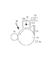
以下に画像形成装置の概略構成について説明する。図1はYMCKの各色の画像形成を行う画像形成部(画像形成ユニット)と中間転写体を備えたタンデム方式の画像形成装置の構成を示した図である。画像形成装置は、各色の画像形成部にそれぞれ備えられた感光体1a〜1d(像担持体)と各感光体を帯電するコロナ帯電器2a〜2d(帯電装置)を備える。
(1) Overall configuration of image forming apparatus A schematic configuration of the image forming apparatus will be described below. FIG. 1 is a diagram showing a configuration of a tandem type image forming apparatus including an image forming unit (image forming unit) for forming an image of each color of YMCK and an intermediate transfer member. The image forming apparatus includes
感光体1a〜1dの周囲には、感光体の回転方向(矢印反時計回り)に沿って順に、帯電装置2a〜2d、露光手段としての露光装置3a〜3d、現像手段としての現像装置4a〜4d、クリーニング装置5a〜5d、転写手段としての一次転写装置6a〜6dと中間転写体7および二次転写装置8、除電装置9a〜9d、転写材格納装置10、機内温湿度検知手段11a〜11c、機外温湿度検出手段12、定着装置13が配設されている、
以下に、上記で挙げた画像形成部について詳述する。尚、本実施例を説明するにあたり、代表して図1における最上流のY色に相当する画像形成部に対してのみ説明するが、b〜d群に対しても同様の機能を有するものとして扱う。
Around the
Hereinafter, the image forming unit mentioned above will be described in detail. In the description of this embodiment, only the image forming unit corresponding to the most upstream Y color in FIG. 1 will be described as a representative, but the same function is assumed for the groups b to d. deal with.
■感光体
本実施例では、感光体1a〜1dとして回転ドラム型の電子写真感光体を備えている。この感光体1a〜1dは負帯電特性のOPC(有機光半導体)で形成された感光層を有している。感光体1a〜1dは直径84mm、長手方向の長さは370mmである。この感光体1はドラムの中心を軸として約350mm/secのプロセススピード(周速度)で図1中矢印方向に回転駆動される。
(2) Photoreceptor In this embodiment, as the
また、本実施例の感光体は、一般的な有機感光体の層構造を呈している。具体的には、感光体1a〜1dは径方向内側に導電性基体であるアルミニウム製シリンダーを有している。
In addition, the photoconductor of this embodiment has a general organic photoconductor layer structure. Specifically, the
そして、このシリンダー上にシリンダー欠陥に伴う光の干渉抑制及び、上層で発生した電荷の輸送を妨げないようにするための下引き層、電荷発生層で発生したホールの通過を抑制し、電子のみの通過させるための注入阻止層、光照射による電荷を発生させるための電荷発生層、電荷を輸送するための電荷輸送層、クリーニング性向上の為の表面保護層から成る。 And on this cylinder, suppression of light interference due to cylinder defects and suppression of the passage of holes generated in the charge generation layer, the undercoat layer in order not to disturb the transport of charges generated in the upper layer, only electrons An injection blocking layer for passing light, a charge generation layer for generating charges by light irradiation, a charge transport layer for transporting charges, and a surface protective layer for improving cleaning properties.
■帯電装置(非接触帯電部材)
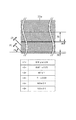
以下に本実施例における帯電装置としてのコロナ帯電器(スコロトロン)について説明する。図2は本実施例に係る画像形成ユニットの一例を示す断面図である。本実施例のコロナ帯電器2aは、図2に示すように放電電極としての放電ワイヤ21aと、これを囲むように設けられたコの字状の導電性シールド23aと、このシールドの開口部に設置されたグリッド電極22aを有する。コロナ帯電器2aは、図2に示すように感光体1aの表面に対向して設けられ、放電ワイヤ21aから放電を行うことによって感光体1aの表面を帯電する。
■ Charging device (non-contact charging member)
A corona charger (scorotron) as a charging device in this embodiment will be described below. FIG. 2 is a cross-sectional view illustrating an example of an image forming unit according to the present embodiment. As shown in FIG. 2, the
放電ワイヤ21aにはステンレススチール、ニッケル、タングステンを用いるのが良い。本実施例においては金属の中で非常に安定性の高いタングステンを放電ワイヤに使用した。
Stainless steel, nickel, or tungsten is preferably used for the
タングステンを放電ワイヤに使用することで、加熱、オゾン環境下という苛酷な条件下で、安定したコロナ放電を行う事ができ、長期間に渡り安定使用することが可能となる。 By using tungsten for the discharge wire, stable corona discharge can be performed under severe conditions such as heating and ozone environment, and stable use over a long period of time can be achieved.
放電ワイヤ21aは、図9に示すように電気的なシールド作用を為すステンレス鋼(以下SUSと称す)から成る導電性シールド23aと一体化された調整螺子24aによって一定の張力で保持され、絶縁材料から成る保持部材によって放電ワイヤ21aとシールド23aは電気的に絶縁が保たれている。
放電ワイヤ2aは直径40μm〜100μmにすることが好ましい。放電ワイヤ21aの直径が小さすぎると放電によるイオンの衝突で切断してしまう。逆に放電ワイヤ21aの直径が大きすぎると安定したコロナ放電を得る為に放電ワイヤ21aに印加する電圧が高くなってしまう。
As shown in FIG. 9, the
The
印加電圧が高いと、オゾンが発生しやすく画像流れの発生確率が高くなり、更に、電源コストが上昇してしまう等の問題が生じる。 When the applied voltage is high, ozone is likely to be generated, and the probability of image flow is increased, and further, the power supply cost is increased.
本実施例においては、放電ワイヤ21aの直径は60μmのタングステンワイヤを起用した。放電ワイヤ21aによりコロナ放電を発生させた電荷に対して定電圧電源(不図示)に接続されたグリッド電極22aのバイアス制御により整流効果を発生させ、感光体1aに付与される電荷量を調整し帯電電位を制御する。
In this embodiment, a tungsten wire having a diameter of 60 μm was used as the
図3に本実施例に係るグリッド電極22aの要部構成図を示す。本実施例ではグリッド電極22aとして、複数の開孔(貫通孔)がメッシュ状に形成されたものを適用した。
FIG. 3 shows a configuration diagram of a main part of the
本実施例で用いたグリッド電極22aの基材は、オーステナイト系ステンレス鋼(SUS304)で形成された厚さ0.03mmの板金に、エッチング加工によって複数の開孔(貫通孔)が形成されたものである。
The base material of the
エッチング加工が施されたグリッド電極22aは、内部がメッシュ形状になっている。図3に示すように開孔は、基線に対して斜め45±1°、幅0.071±0.03mmで、開口幅0.312±0.03mmの間隔で形成されている。
The
また、グリッド電極12には、撓みを防止するために、6.9±0.1mmごとに、幅0.1±0.03mmの梁が長手方向に設けられている。外枠の幅で1.5±0.1mmである。
The
また、グリッド電極22aは、SUSで形成された基材上に、テトラヘデラルアモルファスカーボン(Tetrahedral Amorphous Carbon:以下「ta−C」。)で形成された表面層を有している。
The
ta−Cは、コロナ放電によって発生する放電生成物に対して化学的に不活性な材料であり耐腐食性に優れた材料として本実施系において適用した。以下、SUSで形成された基材を「SUS基材」、ta−Cで形成された表面層を「ta−C層」とする。 ta-C is a material that is chemically inert to discharge products generated by corona discharge and is applied in the present system as a material having excellent corrosion resistance. Hereinafter, the base material formed of SUS is referred to as “SUS base material”, and the surface layer formed of ta-C is referred to as “ta-C layer”.
ta−C層を用いたグリッド電極22aは、SUS基材の酸化、電解腐食の発生を抑制することができ、長期間にわたって帯電ムラの少ない安定した帯電を維持することができる。
The
なお、基材の材料は、上記のオーステナイト系ステンレス鋼(SUS304)に限定されるわけではなく、他のオーステナイト系ステンレス鋼を使用してもよい。また、マルテンサイト系ステンレス鋼やフェライト系ステンレス鋼などの他のステンレス鋼を使用してもよい。 The material of the base material is not limited to the austenitic stainless steel (SUS304), and other austenitic stainless steel may be used. Further, other stainless steels such as martensitic stainless steel and ferritic stainless steel may be used.
また、このコロナ帯電器2aは、帯電バイアスを印加する帯電バイアス印加手段としての高圧電源14aが接続されており、放電ワイヤ21a及びグリッド電極22aに対して帯電バイアスを印加する。
高圧電源14aから印加された帯電バイアスは、感光体1aの表面を負極性の電位に一様に帯電処理を行う機能を担っている。
The
The charging bias applied from the high
具体的には、放電ワイヤ21aに−1mAの定電流制御、グリッド電極22aには、本実施例では通常作像時(本実施例では以降第一モードと称する)においては約−900vの定電圧制御となるよう制御されている。
尚、本発明の特徴である帯電器傾き調整時における高圧条件については後述にて説明する。
Specifically, a constant current control of -1 mA is applied to the
Note that the high voltage condition at the time of adjusting the inclination of the charger, which is a feature of the present invention, will be described later.
■その他の画像形成部について
露光手段としての露光装置3aは本実施例では、半導体レーザ光源とポリゴンミラー光学系とを用いたレーザービーム走査露光装置である。例えば、コロナ帯電器2aの放電ワイヤ21aに対して定電流制御で−1mAを印加、グリッド電極22aに−900vを印加された場合、感光体1a上の帯電電位は約−800vに帯電される(暗部電位)。帯電された感光体1aの表面は露光装置3の露光により約−300vに変化する(明部電位)。このようにして、露光装置3aによって感光体の表面が露光され、感光体の表面に静電潜像が形成される。
(2) Other Image Forming Unit In this embodiment, the
現像手段としての現像装置4aは、露光装置3aによって感光体1aの表面に形成された静電潜像に現像剤(トナー)を供給して現像することで静電潜像をトナー像として顕像化し、感光体1aの表面にトナー像を形成する。現像装置4aは二成分磁気ブラシ現像方式の反転現像装置を適用した。
The developing
現像装置4aは、現像容器、現像スリーブを有している。現像容器内には、二成分現像剤が収容されている。二成分現像剤は、トナーと磁性キャリアとの混合物である。トナーとキャリアを重量比で約8:92の割合で混合したトナー濃度(TD比)8%の二成分現像剤を用いる。トナーは、ポリエステルを主体とした樹脂バインダーに顔料を混練したものを粉砕分級して得られた平均粒径が約6μのトナーである。キャリアは、例えば表面酸化領域は、未酸化の鉄、ニッケル、コバルト、マンガン、クロム、希土類等の金属及びそれらの合金或いは、酸化物フェライト等が好適に使用可能であり、これらの磁性粒子の製造方法は特に制限されない。キャリアは、体積平均粒径が20〜50μm、好ましくは30〜40μmであり、抵抗率が107Ωcm以上、好ましくは108Ωcm以上である。
The developing
ここでは、フェライトを主とするコアにシリコン樹脂をコートしたキャリアを用い、体積平均粒径が35μm、抵抗率が5×10⁸Ωcm、磁化量が200emu/ccである。 Here, a carrier in which a core mainly made of ferrite is coated with a silicon resin is used, the volume average particle size is 35 μm, the resistivity is 5 × 10 8 Ωcm, and the magnetization is 200 emu / cc.
現像スリーブは、感光体1aとの最近接距離を250μmに保持した状態で、感光体1aに近接するように対向配設されている。感光体1aと現像スリーブとの対向部が現像部となる。
The developing sleeve is disposed to face the
現像スリーブは、その表面が現像部において感光体1a表面の移動方向と順方向に回転駆動される。現像スリーブは、内側にマグネットローラを備え、その磁力により、二成分現像剤が現像スリーブの回転に伴って現像部に回転搬送される。
The surface of the developing sleeve is driven to rotate in the forward direction and the moving direction of the surface of the
現像スリーブの表面に形成される磁気ブラシ層は、現像剤コーティングブレードにより所定の薄層に整層され、現像スリーブには現像バイアス印加手段としての現像バイアス印加電源から所定の現像バイアスが印加される。 The magnetic brush layer formed on the surface of the developing sleeve is layered into a predetermined thin layer by a developer coating blade, and a predetermined developing bias is applied to the developing sleeve from a developing bias applying power source as a developing bias applying means. .
第1のモードとしての通常画像形成時においては、現像スリーブに印加される現像バイアスは、直流電圧と交流電圧を重畳した振動電圧である。具体的には、感光体1a表面の帯電電位が−800vの時、直流電圧が−620v、交流電圧が1300Vpp、周波数10kHzを印加した。現像バイアスによる電界によって、感光体1a上の静電潜像に対応して二成分現像剤中のトナーが選択的に付着される。これにより、静電潜像がトナー像として現像される。
During normal image formation as the first mode, the developing bias applied to the developing sleeve is an oscillating voltage in which a DC voltage and an AC voltage are superimposed. Specifically, when the charged potential on the surface of the
この時、感光体1a上に現像されたトナーの帯電量は約40μC/gである。現像部を通過した現像スリーブ上の現像剤は、引き続き現像スリーブの回転に伴い現像容器内の現像剤溜り部に戻される。
At this time, the charge amount of the toner developed on the
現像されるトナーは耐久や環境によってその帯電量が変動する。トナーが新品の状態ではトナーの帯電量は比較的高い値であるが、使用によるトナーやキャリアが劣化し、トナーの帯電量が低下してくる。また、環境によってもトナーの帯電量は変動する。そこで、例えば、劣化したトナーを現像装置外に吐き出す制御を行い新しいトナーをトナーボトルから補給する動作や、トナーとキャリアを攪拌させる動作を行うことによってトナーの帯電量を通常の画像形成に支障が出ない範囲に調整する制御を行っている。本実施例においてはトナーの単位質量あたりの帯電量が10μC/g〜45μC/gの範囲内となるように上述した制御を行っている。しかし、上記の範囲内でトナーの帯電量は変動する。例えば、新品のトナーの帯電量は比較的高く40μC/g以上だが、使用に伴い劣化することによってトナーの帯電量が例えば約30μC/g前後まで低下する。 The charge amount of the toner to be developed varies depending on durability and environment. When the toner is new, the charge amount of the toner is relatively high, but the toner and carrier due to use deteriorate and the charge amount of the toner decreases. Also, the toner charge amount varies depending on the environment. Therefore, for example, by controlling the discharge of deteriorated toner out of the developing device and replenishing new toner from the toner bottle or agitating the toner and the carrier, the charge amount of the toner is hindered in normal image formation. The control is adjusted so that it does not come out. In this embodiment, the above-described control is performed so that the charge amount per unit mass of the toner is within the range of 10 μC / g to 45 μC / g. However, the charge amount of the toner varies within the above range. For example, the charge amount of a new toner is relatively high and is 40 μC / g or more. However, the charge amount of the toner decreases to, for example, about 30 μC / g due to deterioration with use.
本実施例では、感光体1a上のトナー像の転写手段として中間転写体ベルト7(中間転写体)と転写ローラ6aを適用した。転写ローラ6aは、中間転写体ベルト7を介して感光体1a表面に所定の押圧力を持って圧接されており、両者の圧接ニップ部が転写部となる。転写ローラ6aは、温度23℃湿度50%の測定環境下で+2kv印加時の抵抗値が1×10²〜1×10⁸Ω/□のものを用いることが好ましい。
In this embodiment, the intermediate transfer belt 7 (intermediate transfer member) and the
本実施例では、ニトリルゴムとエチレン−エピクロルヒドリン共重合体との混合により形成された、外径16mm、芯金径8mmのイオン導電性スポンジローラを用いた。 In this example, an ion conductive sponge roller formed by mixing nitrile rubber and ethylene-epichlorohydrin copolymer and having an outer diameter of 16 mm and a core metal diameter of 8 mm was used.
中間転写体ベルト7は、感光体1aと転写ローラ6aとの間に挟持されて搬送される。本実施形態で使用する中間転写体は、多様化した記録材への対応を図るべく、表面が柔らかい弾性層を有するベルトを採用した。中間転写体ベルトは、表面の凹凸がある記録材の転写抜けを防止し、コート紙やOHP紙等で発生しやすい「中抜け」と呼ばれる転写不良を防止する。中間転写体ベルト7は基材、弾性層、コート層の3層構造で総厚約360μmである。基材は、厚さ80〜90μmの導電性ポリイミド樹脂材料で構成される。弾性層は、基材の上にクロロプレンゴムを200〜300μm積層して形成されJIS―A硬度が60度である。コート層は担持したトナー粒子や記録材の離型性を確保するもので、ポリウレタン樹脂のバインダーにフッ素樹脂を分散させた厚さ5〜15μm程の最表層である。
The
中間転写体ベルト7の抵抗は、体積抵抗率が1×10⁹〜1×10¹¹Ω・cmに調整され、表面抵抗率が1×10¹¹〜1×10¹³Ω/□に調整されている。画像形成時、転写ローラ6aに対してトナーの正規帯電極性である負極性とは逆極性である正極性の転写バイアス電圧(例えば+1500v)が印加される。これにより中間転写体の表面に感光体1a上のトナー像が順次静電的に転写されていく。
The resistance of the
中間転写体7上に転写されたトナー像は記録材格納装置10より搬送された記録材と転写手段としての2次転写装置8によって記録材に転写される。トナー像が転写された記録材は、定着装置13によって加熱及び加圧を受け、トナー像が溶融定着されて画像形成装置外に出力される。
The toner image transferred onto the
クリーニング装置5aは、中間転写体7に転写されずに感光体上に残留した転写残トナーをクリーニングする為の装置である。本実施例ではブレードクリーニングを適用したが、これに限定されず、ファーブラシ等を付加しても良い。
The
制御部(不図示)は例えばCPU等の演算機能を備えてプログラムされる通常のコンピュータ制御装置であって、画像形成装置の各部を総合的に制御して、画像形成を実行させる。 The control unit (not shown) is a normal computer control device programmed with a calculation function such as a CPU, for example, and comprehensively controls each unit of the image forming apparatus to execute image formation.
■アナログ画像出力モード(第2のモード)
本実施例に係る本画像形成装置は、後述するように、露光手段による静電潜像の形成を実質的に行わずに、少なくとも1枚の出力画像範囲内において、コロナ帯電器に印加する帯電高圧である帯電バイアス及び現像装置に印加する現像バイアスの少なくとも一方を2水準以上変化させることにより、現像バイアスの直流電圧値と感光体表面のトナー像が形成される領域の電位との電位差である現像コントラストがそれぞれ異なるコロナ帯電器の傾き調整用の複数のトナー像を現像(アナログ現像)し、記録材に転写して自動的に出力させる第2のモードとしてのアナログ画像出力モードを有する。このモードにより出力された記録材上の調整用のトナー像の主走査方向(感光体1aの回転軸線方向)の濃度のムラ(主走査方向の濃度の変化)をオペレータやサービスマンが目視によって確認する。確認した結果、コロナ帯電器が感光体の表面に対して傾いていると判断した場合、出力された調整用トナー像の確認結果に基づいて感光体1aの回転軸線方向に関するコロナ帯電器の傾き(コロナ帯電器の長手方向における感光体の表面との間隔)を調整できるようになっている。本実施例では、図2に示す帯電装置2aの放電ワイヤ21a及びグリッド電極22aが感光体1a表面の主走査方向に対する垂直面内において傾き角が変更可能になされている。傾き調整機構に関しては、別項目にて後述する。
■ Analog image output mode (second mode)
As will be described later, the image forming apparatus according to the present exemplary embodiment does not substantially form an electrostatic latent image by the exposure unit, and charges the corona charger within at least one output image range. This is a potential difference between the DC voltage value of the developing bias and the potential of the area where the toner image is formed on the surface of the photosensitive member by changing at least one of the high-voltage charging bias and the developing bias applied to the developing device by two or more levels. There is an analog image output mode as a second mode in which a plurality of toner images for adjusting the inclination of corona chargers having different development contrasts are developed (analog development), transferred to a recording material and automatically output. An operator or a serviceman visually confirms density unevenness (change in density in the main scanning direction) of the toner image for adjustment on the recording material output in this mode in the main scanning direction (rotation axis direction of the
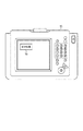
本実施例では、アナログ画像出力モードを実行する為の入力手段(指示手段)として、図4に示すように、本体に設けられた操作部としての操作パネル15上の実行ボタン16が設けられている。この実行ボタン16を押すことによって、アナログ画像を出力する為の画像形成条件を設定し、調整用のトナー像が自動的に出力される構成となっている。
In this embodiment, as an input means (instruction means) for executing the analog image output mode, as shown in FIG. 4, an
以下にアナログ画像出力モード実行時における制御フローを述べる。 The control flow when executing the analog image output mode will be described below.
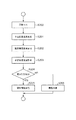
図5に、本実施例のアナログ画像出力モード実行時におけるフローチャートを示す。
S100:オペレータやサービスマンにより、アナログ画像出力モード実行する為の入力手段としての実行ボタン16が押されることによりアナログ画像出力モードの制御が開始される。
S101:実行手段としての制御部は、通常画像形成時(以降第1のモードと称す)における現像バイアスや帯電バイアス等の各高圧の画像出力条件を決定する為の制御を実施する。
S102:制御部は、S101における制御が正常に終了したかどうかを判断する。S101における制御が正常に終了しなかった場合(異常時)にはS105に移行し、エラー情報を表示する。
S103:制御部は、S101の制御により決定された高圧条件に基づきアナログ画像出力モードに使用する為の高圧条件を決定する。
S104:制御部は、アナログ画像出力モードが第1のモードと画像出力条件が異なっている為、エラーになる条件を解除しエラー判定をしない制御を実施
S105:制御部は、S102において異常時と判断した場合、エラーを表示し、画像形成装置動作を停止する。
S106:制御部は、画像形成装置に対してアナログ画像出力開始を命令する。
FIG. 5 shows a flowchart when the analog image output mode of this embodiment is executed.
S100: Control of the analog image output mode is started by pressing the
S101: The control unit as an execution unit performs control for determining each high-voltage image output condition such as a developing bias and a charging bias during normal image formation (hereinafter referred to as a first mode).
S102: The control unit determines whether or not the control in S101 has ended normally. If the control in S101 does not end normally (at the time of abnormality), the process proceeds to S105 and error information is displayed.
S103: The control unit determines a high-pressure condition for use in the analog image output mode based on the high-pressure condition determined by the control in S101.
S104: Since the analog image output mode is different from the first mode in the image output condition, the control unit performs control that cancels the error condition and does not perform error determination. If it is determined, an error is displayed and the operation of the image forming apparatus is stopped.
S106: The control unit instructs the image forming apparatus to start analog image output.
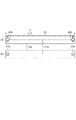
次に、アナログ画像出力モードの実行により出力された調整用トナー像について図6を用いて説明する。 Next, the adjustment toner image output by executing the analog image output mode will be described with reference to FIG.
図6は本実施例に係るアナログ画像出力モード実施時に出力される複数の調整用トナー像の一例を示す図である。 FIG. 6 is a diagram illustrating an example of a plurality of adjustment toner images output when the analog image output mode according to the present embodiment is performed.
本実施例におけるアナログ画像出力モードでは、副走査方向19インチ、主走査13インチサイズの1枚の記録材にアナログ画像出力モードにおける複数の調整用トナー像を形成させる。100はトナー像が形成されない余白部としてのベタ白画像を示し、101および102がアナログ画像出力モードにおいて形成される調整用トナー像を示し、この2つの調整用トナー像はそれぞれ各高圧条件を異ならせて異なる現像コントラストに設定することにより異なる濃度に形成される。具体的には、第1の調整用トナー像101はトナーの単位質量あたりの帯電量が45μC/gである時に平均濃度が0.4〜0.8の範囲内となるように現像コントラストが設定され、第2の調整用トナー像102はトナーの単位質量あたりの帯電量が30μC/gである時に平均濃度が0.4〜0.8の範囲内となるように現像コントラストが設定されて調整用トナー像の形成が行われる。その結果、1枚の記録材に第1の調整用トナー像101と第1のトナー像101よりも平均濃度が薄い第2の調整用トナー像102の2つの調整用トナー像が形成されることになる。なお、ここで言う平均濃度とは、各トナー像領域全体の平均濃度であり、例えば、主走査方向におけるトナー像両端部および中央部の合計3箇所の濃度を測定し、その平均値を求めても良い。調整用トナー像の濃度は感光体表面の帯電電位の微小な変化による濃度の微小な変化を目視で確認し易い中間調濃度の濃度範囲が好ましく、本発明者らは0.4〜0.8の範囲内が濃度の変化が目視で認識し易い範囲であることを見出した。また、本実施例における濃度とは、記録材としてキヤノン製の上白紙GFC081を用いて出力したアナログ画像の濃度を、X−Rite社製の反射濃度計による数値である。出力するメディアや反射濃度計により調整する濃度の絶対値は適切に調整すればよい。
In the analog image output mode in this embodiment, a plurality of adjustment toner images in the analog image output mode are formed on a single recording material having a size of 19 inches in the sub-scanning direction and 13 inches in the main scanning direction.
尚、本実施例では、1枚の記録材に複数の調整用トナー像を形成することによって使用する記録材を節約することができるがこれに限定されず、複数枚の記録材にそれぞれ1つの調整用トナー像を形成するようにしても良い。 In this embodiment, the recording material to be used can be saved by forming a plurality of adjustment toner images on one recording material. However, the present invention is not limited to this. One recording material is used for each recording material. An adjustment toner image may be formed.
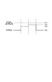
ここで、本実施例におけるアナログ画像出力モード実行時の高圧印加条件の設定およびタイミングについて図8を用いて説明する。 Here, the setting and timing of the high voltage application condition when executing the analog image output mode in the present embodiment will be described with reference to FIG.
図8は本発明の実施例に係る高圧印加タイミングを示した図である。 FIG. 8 is a diagram showing the timing of high voltage application according to the embodiment of the present invention.
図8(a)における制御は、現像手段に印加する現像高圧としての現像バイアスに重畳する直流電圧を第1のモードである通常画像形成時における現像バイアスに重畳する直流電圧と同じ電圧値に設定し、帯電高圧としての帯電バイアスを第1の調整用トナー像と第2の調整用トナー像とで異なる値に設定することにより、それぞれ異なる現像コントラストを設定してアナログ画像を形成するものである。以下に詳細な高圧設定条件を述べる。 In the control in FIG. 8A, the DC voltage superimposed on the development bias as the development high voltage applied to the developing means is set to the same voltage value as the DC voltage superimposed on the development bias at the time of normal image formation which is the first mode. Then, by setting the charging bias as the charging high voltage to different values for the first adjustment toner image and the second adjustment toner image, different development contrasts are set to form analog images. . The detailed high pressure setting conditions are described below.
本制御では、露光装置3aをOFFにした状態で感光体1aを回転させる。次にトナー像が形成されない余白部としてのベタ白画像100を形成する為に、感光ドラム1a表面の帯電電位(V[5])が−800vとなるように帯電高圧を印加する。
In this control, the
本実施例における帯電高圧は、通常画像形成時の高圧条件では、放電ワイヤ21aに−1mAの定電流制御、グリッド電極22aに−900vの定電圧制御とした。ここで帯電電位が−800Vにされる位置は感光体長手方向における所定の位置であり、具体的には感光体の長手方向における一部の帯電電位を検知することができる電位センサーが備えられている場合には長手方向における電センサーが検知することができる位置の帯電電位である。
The charging high voltage in this embodiment was set to a constant current control of −1 mA for the
帯電高圧の印加と共に現像高圧(V[1])を印加する。本実施例では、−620vの直流電圧に周波数10kHz、1300vppの交流電圧を重畳した現像バイアスを現像高圧として印加する。 A developing high voltage (V [1]) is applied together with the charging high voltage. In this embodiment, a developing bias in which an AC voltage having a frequency of 10 kHz and 1300 vpp is superimposed on a DC voltage of −620 v is applied as a developing high voltage.
次に調整用トナー像101、102を形成する為に本実施例では、グリッド電極22aに印加する直流電圧値を変更することにより異なる現像コントラストに設定された2種類の調整用トナー像が作成可能となる。
Next, in this embodiment, in order to form the
本実施例では、感光体1a表面の帯電電位がV[2]=−650v、V[3]=−700vとなるようグリッド電極22aに印加する直流電圧値をV[2]時には−720v、V[3]時には−780V、に設定した。
In this embodiment, the DC voltage value applied to the
所定のタイミングにて変更された感光体1a表面の帯電電位が現像ニップを通過する際にアナログ現像され、第1の調整用トナー像と第2の調整用トナー像が形成される。そして調整用トナー像の現像を終えると、トナー像が形成されない余白部としてのベタ白画像100を形成する為の条件に戻してベタ白画像100が形成されて制御終了となる。
When the charged potential on the surface of the
上記のように、記録材における搬送方向両端部にトナー像が形成されない余白部としてのベタ白画像100を形成することにより、アナログ画像出力モードにより形成されたトナー像が記録材の領域からはみ出すことによって2次転写装置8が汚れることを抑制することができる。
As described above, by forming the solid
本実施例では、代表としてY色におけるアナログ画像出力モードの制御例を述べたが、Y〜K色の調整用トナー像を1枚の記録材に形成して出力するようにしても良い。この場合、各色の調整用トナー像群同士が重畳しないよう形成するのが好ましい。また、複数枚の記録材に分けて出力する場合にも同様に各色の調整用トナー像群同士が重畳しないよう形成するのが好ましい。 In this embodiment, the control example of the analog image output mode for Y color has been described as a representative. However, an adjustment toner image for Y to K colors may be formed on one recording material and output. In this case, it is preferable to form the adjustment toner image groups of the respective colors so as not to overlap each other. Similarly, when outputting separately to a plurality of recording materials, it is preferable to form the toner image groups for adjustment of each color so as not to overlap each other.
本実施例においては、温度23℃湿度50%の環境下において電位センサーによって検知可能な領域の感光体表面の帯電電位が所定の電位になるようにグリッド電極に印加する電圧を設定したが、この設定方法に特に限定されるものではない。 In this embodiment, the voltage applied to the grid electrode is set so that the charged potential on the surface of the photoreceptor in the region detectable by the potential sensor in an environment of temperature 23 ° C. and humidity 50% becomes a predetermined potential. The setting method is not particularly limited.
例えば、図1に示される11a〜11c、12の温湿度検知手段を用いて、環境に応じた感光体の特性変化を考慮して高圧条件を変更するように構成しても良い。 For example, the high-pressure conditions may be changed by using the temperature / humidity detection means 11a to 11c and 12 shown in FIG.
また、電位センサーを備えた構成に限らず、電位センサーを有しておらず感光体の電位と帯電バイアスの関係が予め記憶されており、当該関係に基づいて帯電バイアスを設定するように構成されていても良い。 Further, the present invention is not limited to the configuration including the potential sensor, and the relationship between the potential of the photoconductor and the charging bias is stored in advance without the potential sensor, and the charging bias is set based on the relationship. May be.
アナログ画像出力モードを実行した後、オペレータ又はサービスマンは出力された調整用トナー像を目視で確認する。複数の調整用トナー像のうち、主走査方向における両端部間で濃度の差を検知した場合にコロナ帯電器が傾いていると判断し、後述するコロナ帯電器2aの傾き調整手段を用いてコロナ帯電器の長手方向における感光体の表面とコロナ帯電器との間隔を調整する。
After executing the analog image output mode, the operator or service person visually confirms the output adjustment toner image. Of the plurality of toner images for adjustment, when a difference in density is detected between both ends in the main scanning direction, it is determined that the corona charger is tilted, and the
調整用トナー像の濃度を測定することができる濃度計がある場合には、濃度計を用いることもできる。この場合、各調整用トナー像の主走査方向における中心位置での画像濃度をX−Rite社製の反射濃度計を用いて測定し、濃度0.6±0.2の調整用トナー像を選択する。 If there is a densitometer that can measure the density of the toner image for adjustment, a densitometer can also be used. In this case, the image density at the center position in the main scanning direction of each adjustment toner image is measured using a reflection densitometer manufactured by X-Rite, and the adjustment toner image having a density of 0.6 ± 0.2 is selected. To do.
そして選択した調整用トナー像の主走査方向における両端部の濃度を測定し、両端部間に0.02よりも大きい濃度差がある場合、濃度差が0.02以下になるように後述するコロナ帯電器2aの傾き調整手段を用いて調整する。
Then, the density of both ends of the selected adjustment toner image in the main scanning direction is measured, and when there is a density difference larger than 0.02 between the both ends, a corona described later so that the density difference becomes 0.02 or less. Adjustment is performed using the inclination adjusting means of the
図7は、濃度計を用いた場合の濃度測定時におけるサービスマン或いは、オペレータによる実施フローを示す。
S200:アナログ画像形成モードの実行により画像形成装置から調整用トナー像を出力する。
S201:サービスマンあるいはオペレータにより出力された調整用トナー像の主走査方向における中心位置の濃度、図6に示す104の黒塗り●部の濃度を測定する。
S202:サービスマンあるいはオペレータは、測定された濃度が濃度0.6±0.2の範囲内の調整用トナー像を選択する。
S203:サービスマンあるいはオペレータは、選択した調整用トナー像の主走査方向における両端部の濃度、図6に示す105及び106の黒塗り●部の濃度を測定する。
S204:サービスマンあるいはオペレータは、両端部の濃度差が0.02よりも大きいかどうか判断する。
S205:サービスマンあるいはオペレータは、両端部の濃度差が0.02よりも大きいと判断した場合、コロナ帯電器の傾き調整フローに移行する。
S206:サービスマンあるいはオペレータは、0.02以下であると判断した場合、コロナ帯電器の傾き調整は不要であると判断する。
FIG. 7 shows an execution flow by a service person or an operator at the time of concentration measurement using a densitometer.
S200: The adjustment toner image is output from the image forming apparatus by executing the analog image forming mode.
S201: The density of the central position in the main scanning direction of the toner image for adjustment output by the service person or the operator, and the density of the black-filled
S202: The service person or operator selects an adjustment toner image whose measured density is in the range of density 0.6 ± 0.2.
S203: The service person or the operator measures the density of both ends of the selected adjustment toner image in the main scanning direction, and the density of the black and
S204: The service person or the operator determines whether the density difference between both ends is greater than 0.02.
S205: If the serviceman or the operator determines that the density difference between both ends is greater than 0.02, the process proceeds to the corona charger inclination adjustment flow.
S206: If the serviceman or the operator determines that the value is 0.02 or less, the serviceman or the operator determines that the corona charger inclination adjustment is unnecessary.
■帯電器傾き調整手段(グリッド電極22aによる傾き調整)
本実施例におけるコロナ帯電器の傾きを調整するための帯電器傾き調整手段について詳細に説明する。
■ Charger tilt adjustment means (tilt adjustment by
The charger inclination adjusting means for adjusting the inclination of the corona charger in this embodiment will be described in detail.
本実施例においては、グリッド電極22aによる傾き調整により感光体の表面に対するコロナ帯電器の傾きを調整する。
In this embodiment, the inclination of the corona charger with respect to the surface of the photoreceptor is adjusted by adjusting the inclination by the
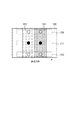
グリッド傾き調整手段26aは、図9に示すように、支持部としての支持片27、固定手段としての固定ビス27a、27b、位置調整部材29および螺子部材28を備えている。
As shown in FIG. 9, the grid inclination adjusting means 26 a includes a
図9(a)は調整機構を正面からみた図であり図9(b)はその断面図となる。
コロナ帯電器2aの一端側に設けられている支持片27は、第一の傾斜面29aはブロック30に固定ビス27a、27bを介して取り付けられている。支持片27は前カバー31からねじ込まれた固定ビス27a、27bを例えばドライバー等の工具で締め付けることでブロック30に固定される。また、支持片27は、固定ビス27a、27bを緩めることで、ブロック30に対して上下方向(感光体1aに対して接近離間する方向)にスライド可能な構成となっている。
FIG. 9A is a view of the adjustment mechanism as viewed from the front, and FIG. 9B is a cross-sectional view thereof.
The
ここで支持片27は、画像形成装置のコロナ帯電器位置決め部材(不図示)に係合する帯電器位置決め穴27d、27eが設けられている。一方他端側にも画像形成装置に対する位置を決めるための位置決め部材(不図示)を設けており、こちら側は一意に決まるため調整機構は設けていない。
Here, the
したがって、支持片27の帯電器位置決め穴27d、27eが画像形成装置に対して係合した状態においては、固定ビス27a、27bを緩めることで、ブロック30が感光体1aに対して接近離間移動可能に支持片27に支持される。
Accordingly, in a state where the
位置調整部材29は図9に示すようにブロック30内で支持片27に対向していて前後方向に移動可能に配置されている。また、位置調整部材29には支持片27の第一の斜面29aに係合する第二の傾斜面29bが形成されている。
As shown in FIG. 9, the
螺子部材28はブロック30の前カバー31を介して位置調整部材29に螺合されている。螺子部材28は軸方向の移動が規制されており、調整用操作部としての螺子頭が前カバー31から露出している。
The
螺子部材の頭部をドライバー等の工具で回転操作することにより、螺子部材28が回転して位置調整部材29が前後方向に移動する。このとき位置調整部材29の第二の斜面29bは支持片27の第一の傾斜面29aに係合しているので、カム作用により支持片27がブロック30に対して上下方向に相対移動する。よってこの回転量により感光体1aに対する帯電器本体の接近離間量すなわち感光体1aの表面に対するグリッド電極の間隔を調節する事が可能となる。
By rotating the head of the screw member with a tool such as a screwdriver, the
なお、グリッド傾き調整手段26aはコロナ帯電器の長手方向における一方の端部に設けられている。 The grid inclination adjusting means 26a is provided at one end in the longitudinal direction of the corona charger.
本実施例に基づき、両端の濃度差がありコロナ帯電器の傾きを調整する必要があると判断した場合における以下の2つの条件を想定し、その際のコロナ帯電器傾き調整について説明する。 Based on the present embodiment, assuming the following two conditions when it is determined that there is a density difference at both ends and the inclination of the corona charger needs to be adjusted, the adjustment of the corona charger inclination at that time will be described.
[1]調整用トナー像における、コロナ帯電器のグリッド傾き調整手段26aが設けられている側の端部に対応する端部の濃度が他方の端部の濃度よりも薄い場合
図9に示す固定ビス27a、27bを緩め螺子部材28を反時計回りに回転することにより感光体1aに対してグリッド電極を接近させる。
[1] When the density of the end corresponding to the end of the corona charger on the side where the grid inclination adjusting means 26a is provided in the toner image for adjustment is thinner than the density of the other end The grid electrodes are brought closer to the
[2]調整用トナー像における、コロナ帯電器のグリッド傾き調整手段26aが設けられている側の端部に対応する端部の濃度が他方の端部の濃度よりも濃い場合
図9に示す固定ビス27a、27bを緩め螺子部材28を時計回りに回転することにより感光体1aに対してグリッド電極を離間させる。
[2] When the density of the end corresponding to the end of the corona charger on the side where the grid inclination adjusting means 26a is provided in the adjustment toner image is higher than the density of the other end. The grid electrodes are separated from the
本実施例によれば、アナログ画像出力モードにおいて、トナーの単位質量あたりの帯電量が45μC/gである時に平均濃度が0.4〜0.8の範囲内となるように形成された第1の調整用トナー像と、トナーの単位質量あたりの帯電量が30μC/gである時に平均濃度が0.4〜0.8の範囲内となるように形成された第2の調整用トナー像を出力することにより、トナーが新しくトナーの単位質量あたりの帯電量が比較的高く45μC/g近傍である場合には第1の調整用トナー像によって目視でトナー像の主走査方向における濃度のムラを確認することができ、トナーの耐久が進んだ事によってトナーの単位質量あたりの帯電量が30μC/g近傍まで下がった場合においても第2の調整用トナー像によって目視でトナー像の主走査方向における濃度のムラを確認することができる。その結果、トナーの帯電量が変化した場合においても、コロナ帯電器の長手方向における感光体の表面との間隔を精度良く調整することが可能となる。 According to this embodiment, in the analog image output mode, the first density formed so that the average density is in the range of 0.4 to 0.8 when the charge amount per unit mass of the toner is 45 μC / g. An adjustment toner image and a second adjustment toner image formed so that the average density is in the range of 0.4 to 0.8 when the charge amount per unit mass of the toner is 30 μC / g. When the toner is new and the charge amount per unit mass of the toner is relatively high and is in the vicinity of 45 μC / g, the density unevenness in the main scanning direction of the toner image is visually observed by the first adjustment toner image. Even when the charge amount per unit mass of the toner is reduced to the vicinity of 30 μC / g due to the progress of the durability of the toner, the second adjustment toner image visually confirms the main scanning method of the toner image. It is possible to confirm the non-uniformity of the concentration in. As a result, even when the charge amount of the toner changes, the distance from the surface of the photoconductor in the longitudinal direction of the corona charger can be accurately adjusted.
実施例1においては、グリッド電極を有するコロナ帯電器において、帯電高圧としてグリッド電圧に印加する直流電圧値を設定することによって複数の現像コントラストに基づく複数の調整用トナー像を形成する例を記載したが、本実施例では放電ワイヤに印加する直流電圧を制御することによって複数の調整用トナー像を形成する場合ついて説明する。なお、実施例1と同一の構成については同一符号を付すことにより重複する説明は適宜省略する。 In the first embodiment, in the corona charger having a grid electrode, an example in which a plurality of adjustment toner images based on a plurality of development contrasts is formed by setting a DC voltage value applied to the grid voltage as a charging high voltage is described. However, in this embodiment, a case where a plurality of toner images for adjustment are formed by controlling the DC voltage applied to the discharge wire will be described. In addition, about the structure same as Example 1, the overlapping description is abbreviate | omitted suitably by attaching | subjecting the same code | symbol.
本実施例のアナログ画像出力モードにおける高圧設定条件では、放電ワイヤに印加する直流電圧の電流値を変更することによって複数の調整用トナー像の現像コントラストを設定する。 Under the high voltage setting condition in the analog image output mode of this embodiment, the development contrast of the plurality of adjustment toner images is set by changing the current value of the DC voltage applied to the discharge wire.
具体的には、感光体1a表面の帯電電位がV[2]=−650v、V[3]=−700vとなるように放電ワイヤ21aに印加する直流電圧の電流値をV[2]時には−0.6μA、V[3]時には−0.75μA、に設定した。
Specifically, the current value of the DC voltage applied to the
所定のタイミングにて変更された感光体1a表面の帯電電位が現像ニップを通過する際にアナログ現像され、第1の調整用トナー像と第2の調整用トナー像が形成される。そして調整用のトナー像の現像を終えると、ベタ白画像100を形成する為の条件に戻して制御終了となる。
When the charged potential on the surface of the
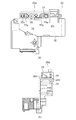
■帯電器傾き調整手段(放電ワイヤ21aによる傾き調整)
本実施例における放電ワイヤ21aを利用した傾き調整手段について述べる。図10はコロナ帯電器2aの傾き調整手段の構造のみを抽出した要部断面図である。図10(a)は、コロナ帯電器2aを主走査方向に分断した時の断面を、図10(b)は図中矢印Aからの俯瞰図を示す。
■ Charger inclination adjustment means (Inclination adjustment by
An inclination adjusting means using the
帯電器傾き調整手段は、導電性シールド23aに当接して設けられた螺旋状の調整螺子24aと調整コマ25aを有し、両端の調整コマが放電ワイヤ21aを一定の張力を保持するように設けられている。
The charger inclination adjusting means has a
調整螺子24aはドライバー等の工具にて締め付けあるいは緩めることができる。本実施例では、時計回りに回転させることにより調整コマ25aを上昇、反時計回りに回転させることにより調整コマ25aを下降させることができる。
The adjusting
本実施例に基づき、コロナ帯電器の両端に対応する調整用トナー像の領域の濃度差がありコロナ帯電器の傾きを調整する必要があると判断した場合における以下の2つの条件を想定し、その際の帯電器傾き調整について述べる。 Based on this embodiment, assuming the following two conditions when it is determined that there is a difference in density between the areas of the toner image for adjustment corresponding to both ends of the corona charger and it is necessary to adjust the inclination of the corona charger, The charger inclination adjustment at that time will be described.
[1]図10におけるFに対応する調整用トナー像の領域の濃度がRに対応する調整用トナー像の領域の濃度よりも濃い場合
図10中、R側の調整螺子24aを反時計回りに回転させることにより調整コマ25aを下降させることによりR側の放電ワイヤ21aが感光体側に近づく。
[1] When the density of the adjustment toner image area corresponding to F in FIG. 10 is higher than the density of the adjustment toner image area corresponding to R In FIG. 10, the
その結果、奥側における電位を画像中心位置の電位まで帯電可能となり、両端の濃度差が濃度規格内となるように調整することができる。望ましくは、F側の調整コマ25aも時計回りに回転させ調整をすることにより、R側における調整螺子の可動限界を超えるような調整が発生した場合でも対応可能となる。
As a result, the potential on the back side can be charged to the potential at the center position of the image, and the density difference at both ends can be adjusted to be within the density standard. Desirably, the
[2]図10におけるFに対応する調整用トナー像の領域の濃度がRに対応する調整用トナー像の領域の濃度よりも薄い場合
図10中、F側の調整螺子24aを反時計回りに回転させることにより調整コマ25aを下降させることによりF側の放電ワイヤ21aが感光体側に近づく。
[2] When the density of the adjustment toner image area corresponding to F in FIG. 10 is thinner than the density of the adjustment toner image area corresponding to R In FIG. 10, the
その結果、奥側における電位を画像中心位置の電位まで帯電可能となり、濃度規格内の調整が実施可能となる。望ましくは、R側の調整コマ25aも時計回りに回転させ調整をすることにより、F側における調整螺子の可動限界を超えるような調整が発生した場合でも対応可能となる。
As a result, the potential on the back side can be charged to the potential at the center position of the image, and adjustment within the density standard can be performed. Desirably, the
本実施例によれば、トナーの帯電量が変化した場合においても、コロナ帯電器の長手方向における感光体の表面との間隔を精度良く調整することが可能となる。 According to this embodiment, even when the charge amount of the toner changes, it is possible to accurately adjust the distance from the surface of the photoreceptor in the longitudinal direction of the corona charger.
実施例1および実施例2においては、アナログ画像出力モードにおける複数の調整用トナー像として、トナーの単位質量あたりの帯電量が45μC/gである時に平均濃度が0.4〜0.8の範囲内となるように形成された第1の調整用トナー像と、トナーの単位質量あたりの帯電量が30μC/gである時に平均濃度が0.4〜0.8の範囲内となるように形成された第2の調整用トナー像を出力する例を説明した。 In Example 1 and Example 2, as the plurality of toner images for adjustment in the analog image output mode, the average density is in the range of 0.4 to 0.8 when the charge amount per unit mass of the toner is 45 μC / g. The first toner image for adjustment formed so as to be within, and formed so that the average density is within the range of 0.4 to 0.8 when the charge amount per unit mass of the toner is 30 μC / g. The example of outputting the second toner image for adjustment described above has been described.
本実施例においては、実施例1にて説明したようにトナーの帯電量を通常の画像形成に支障が出ない範囲に調整する制御を行っている。そのため、トナーの単位質量あたりの帯電量が上述した範囲における下限の10μC/gまで低下するケースは少ないが、トナーやキャリアの劣化が更に進行した場合にはトナーの単位質量あたりの帯電量が上述した範囲における下限の10μC/gまで低下する可能性がある。その場合、第1および2の調整用トナー像の平均濃度がいずれも0.4〜0.8の範囲外となる可能性がある。 In this embodiment, as described in the first embodiment, control is performed to adjust the charge amount of the toner within a range that does not hinder normal image formation. For this reason, there are few cases where the charge amount per unit mass of the toner decreases to the lower limit of 10 μC / g in the above-mentioned range, but when the toner or the carrier further deteriorates, the charge amount per unit mass of the toner is increased as described above. The lower limit in the measured range may be reduced to 10 μC / g. In that case, the average density of the first and second adjustment toner images may be outside the range of 0.4 to 0.8.
そこで、本実施例においては、第2の調整用トナー像で想定しているトナーの帯電量よりも更に低下した場合に感光体表面の帯電電位の微小な変化をトナー像の濃度変化として目視で確認できる第3の調整用トナー像を更に形成して出力することを特徴としている。 Therefore, in this embodiment, when the charge amount of the toner assumed in the second adjustment toner image is further reduced, a slight change in the charged potential on the surface of the photoreceptor is visually observed as a change in the toner image density. A third adjustment toner image that can be confirmed is further formed and output.
具体的には、実行手段である制御部は、更に、トナーの単位質量あたりの帯電量が10μC/gである時に平均濃度が0.4〜0.8の範囲内となるように形成した第3の調整用トナー像を前記複数の調整用トナー像の1つとして出力する。 Specifically, the control unit, which is an execution unit, is further formed so that the average density is within the range of 0.4 to 0.8 when the charge amount per unit mass of the toner is 10 μC / g. 3 adjustment toner images are output as one of the plurality of adjustment toner images.
図11は本実施例に係るアナログ画像出力モード実施時に出力される複数の調整用トナー像の一例を示す図である。 FIG. 11 is a diagram illustrating an example of a plurality of adjustment toner images output when the analog image output mode according to the present embodiment is performed.
本実施例におけるアナログ画像出力モードでは、副走査方向19インチ、主走査13インチサイズの1枚の記録材にアナログ画像出力モードにおける複数の調整用トナー像を形成させる。100はトナー像が形成されない余白部としてのベタ白画像を示し、101、102、103がアナログ画像出力モードにおいて形成される複数の調整用トナー像を示し、この3つの調整用トナー像はそれぞれ各高圧条件を異ならせることにより異なる現像コントラストに設定されて異なる濃度となっている。具体的には、第1の調整用トナー像101はトナーの単位質量あたりの帯電量が45μC/gである時に平均濃度が0.4〜0.8の範囲内となるように現像コントラストが設定され、第2の調整用トナー像102はトナーの単位質量あたりの帯電量が30μC/gである時に平均濃度が0.4〜0.8の範囲内となるように現像コントラストが設定され、第3の調整用トナー像103はトナーの単位質量あたりの帯電量が10μC/gである時に平均濃度が0.4〜0.8の範囲内となるように現像コントラストが設定されて調整用トナー像の形成が行われる。その結果、1枚の記録材には、第1の調整用トナー像101、第1の調整用トナー像101よりも平均濃度が薄い第2の調整用トナー像102、第2の調整用トナー像よりも更に平均濃度が薄い第3の調整用トナー像の3つの調整用トナー像が形成されることになる。
In the analog image output mode in this embodiment, a plurality of adjustment toner images in the analog image output mode are formed on a single recording material having a size of 19 inches in the sub-scanning direction and 13 inches in the main scanning direction.
なお、本実施例においても、複数枚の転写材にそれぞれ1つの調整用トナー像を形成するようにしても良い。 Also in this embodiment, one adjustment toner image may be formed on each of a plurality of transfer materials.
ここで、本実施例におけるアナログ画像出力モード実行時の高圧印加条件の設定およびタイミングについて図12を用いて説明する。 Here, the setting and timing of the high voltage application condition when executing the analog image output mode in the present embodiment will be described with reference to FIG.
図12は本発明の実施例に係る高圧印加タイミングを示した図である。
図12(a)における制御は、現像手段に印加する現像高圧としての現像バイアスの直流電圧を第1のモードである通常画像形成時と同じ電圧値に設定し、帯電高圧としての帯電バイアスを第1の調整用トナー像、第2の調整用トナー像、第3の調整用トナー像とで異なる値に設定することにより、それぞれ異なる現像コントラストを設定してアナログ画像を形成するものである。以下に詳細な高圧設定条件を述べる。
FIG. 12 is a diagram showing a high voltage application timing according to the embodiment of the present invention.
In the control in FIG. 12A, the DC voltage of the developing bias applied as the developing high voltage applied to the developing means is set to the same voltage value as in the normal image formation which is the first mode, and the charging bias as the charging high voltage is set to the first voltage. By setting different values for the one adjustment toner image, the second adjustment toner image, and the third adjustment toner image, different development contrasts are set to form analog images. The detailed high pressure setting conditions are described below.
本制御においても、露光装置3aをOFFにした状態で感光体1aを回転させる。次にベタ白画像100を形成する為に、感光ドラム1a表面の帯電電位(V[5])が−800vとなるように帯電高圧を印加する。
Also in this control, the
本実施例においても帯電高圧の印加と共に現像高圧(V[1])を印加する。本実施例では、−620vの直流電圧に周波数10kHz、1300vppの交流電圧を重畳した現像バイアスを現像高圧として印加する。 Also in this embodiment, the developing high voltage (V [1]) is applied together with the charging high voltage. In this embodiment, a developing bias in which an AC voltage having a frequency of 10 kHz and 1300 vpp is superimposed on a DC voltage of −620 v is applied as a developing high voltage.
次に調整用トナー像101〜103を形成する為に本実施例では、グリッド電極22aに印加する直流電圧値を逐次変更することにより複数の調整用のトナー像が作成可能となる。
Next, in order to form the
本実施例では、感光体1a表面の帯電電位がV[2]=−650v、V[3]=−700v、V[4]=−750vとなるようグリッド電極22aに印加する直流電圧値をV[2]時には−720v、V[3]時には−780v、V[4]時には−840vに設定した。
In this embodiment, the DC voltage value applied to the
所定のタイミングにて変更された感光体1a表面の帯電電位が現像ニップを通過する際にアナログ現像され、第1の調整用トナー像と第2の調整用トナー像と第3の調整用トナー像が形成される。そして調整用のトナー像の現像を終えると、ベタ白画像100を形成する為の条件に戻して制御終了となる。
When the charged potential on the surface of the
なお、本実施例においても実施例2のように放電ワイヤに印加する直流電流値を変更することによって第1、第2、第3の調整用トナー像を形成するようにしても良い。 In this embodiment, the first, second, and third toner images for adjustment may be formed by changing the direct current value applied to the discharge wire as in the second embodiment.
本実施例によれば、第2の調整用トナー像で想定しているトナーの帯電量よりも更に低下した場合においても、感光体表面の帯電電位の微小な変化をトナー像の濃度変化として目視で確認でき、コロナ帯電器の長手方向における感光体の表面との間隔を精度良く調整することが可能となる。 According to this embodiment, even when the charge amount of the toner assumed in the second adjustment toner image is further reduced, a slight change in the charged potential on the surface of the photoreceptor is visually observed as a change in toner image density. Thus, it is possible to accurately adjust the distance from the surface of the photoconductor in the longitudinal direction of the corona charger.
実施例1〜3では帯電高圧を複数種類に設定することによって、複数種類の調整用トナー像を形成する例を説明した。 In the first to third embodiments, an example in which a plurality of types of adjustment toner images are formed by setting a plurality of types of charging high voltage has been described.
しかし、調整用トナー像を形成するための高圧設定条件として、帯電高圧を変えずに現像高圧を複数種類に設定しても良く、また、帯電高圧と現像高圧の両方を変えるように設定しても良い。 However, as a high pressure setting condition for forming an adjustment toner image, a plurality of development high pressures may be set without changing the charging high pressure, and both the charging high pressure and the development high pressure may be changed. Also good.
ここで、本実施例における各構成要素における高圧印加条件について図12を用いて述べる。
図12(b)における制御は、帯電高圧を通常画像形成時(第1のモード)と同設定にて印加し、現像高圧条件を異ならせることにより調整用トナー像を形成するものである。以下に詳細な高圧設定条件を述べる。
Here, a high voltage application condition in each component in the present embodiment will be described with reference to FIG.
In the control in FIG. 12B, an adjustment toner image is formed by applying a charging high voltage at the same setting as that during normal image formation (first mode) and changing the development high voltage conditions. The detailed high pressure setting conditions are described below.
本制御は露光装置3aをOFFにした状態で感光体1aを回転させる。次にベタ白画像100を形成する為に、感光体1a表面の帯電電位(V[10])を−800v)、現像バイアスの直流電圧値V[6]=−620vとなるように高圧を印加する。
In this control, the
本実施例における帯電高圧としての帯電バイアスは、放電ワイヤ21aに−1mAの定電流制御、グリッド電極22aに−900vの定電圧制御とした。
In this embodiment, the charging bias as the charging high voltage is constant current control of -1 mA for the
次に調整用トナー像101〜103を形成する為に本実施例では、現像高圧の条件を逐次変更することにより調整用のトナー像が作成可能となる。
Next, in this embodiment, in order to form the
本実施例では、V[7]=−650v、V[8]=−700v、V[9]=−750v、となるよう現像装置4aに直流電圧を印加し、AC電圧は共通して周波数10kHz、1300Vppを印加した。
In this embodiment, a DC voltage is applied to the developing
所定のタイミングにて変更された現像高圧条件で、感光体1aが現像ニップを通過する際に調整用のトナー像としてアナログ現像される。そして所定の調整用のトナー像の現像を終え、記録材に転写されて画像形成装置外に出力されると、ベタ白画像100を形成する為の条件に戻してアナログ画像出力モードが終了する。
Analog development is performed as a toner image for adjustment when the
図12(c)における制御は、ベタ白画像100を出力する時のみ第1のモードと同様の帯電高圧及び現像高圧を印加し、調整用トナー像101〜103出力時に、帯電高圧及び現像高圧条件共に変更することにより調整用トナー像を形成するものである。以下に詳細な高圧設定条件を述べる。
The control in FIG. 12C applies charging high voltage and developing high voltage similar to those in the first mode only when outputting the solid
本制御は、露光装置3aをOFFにした状態で感光体1aを回転させる。次にベタ白画像100を形成する為に、感光体1a上の表面電位(V[18])を−800v)となるように帯電高圧を印加する。
本実施例では、放電ワイヤ21aに−1mAの定電流制御、グリッド電極22aに−900vの定電圧制御とした。同時に現像高圧(V[11])を印加、本実施例では、現像高圧としての現像バイアスに重畳する直流電圧として−620v、交流電圧として周波数10kHz、1300vppを印加する。
In this control, the
In the present embodiment, a constant current control of -1 mA was applied to the
次に調整用トナー像101〜103を形成する為に本実施例では、グリッド電極に印加する直流電圧の条件及び現像バイアスに重畳する直流電圧の条件を逐次変更することにより調整用のトナー像を作成する。
Next, in this embodiment, in order to form the
本実施例では、感光体1a表面の帯電電位がV[15]=−735v、V[16]=−760v、V[17]=−785v、となるようグリッド電極22aに印加する電圧量をV[16]時には−820v、V[17]時には−850V、V[18]時には−880vの定電圧を印加した。上記変更タイミングに対して所定のタイミングにて現像バイアスに重畳する直流電圧をV[12]=−605v、V[13]=−580v、V[14]=−555v、となるよう現像装置4aに直流電圧を印加し、交流電圧は共通して周波数10kHz、1300Vppを印加した。
In this embodiment, the voltage amount applied to the
所定のタイミングにて変更された帯電及び現像高圧条件にて感光体1aが現像ニップを通過する際に調整用のトナー像としてアナログ現像される。そして所定の調整用のトナー像の現像を終ええ、記録材に転写されて画像形成装置外に出力されると、ベタ白画像100を形成する為の条件に戻してアナログ画像出力モードが終了する。
Analog development is performed as a toner image for adjustment when the
尚、出力された画像は実施例1と同様に主走査方向における両端部の濃度差を確認し、その濃度差に応じてコロナ帯電器の傾きを調整することにより、実施例1と同様の効果を奏することができる。調整方法については実施例1と同様であるため割愛する。 The output image confirms the density difference at both ends in the main scanning direction as in the first embodiment, and adjusts the inclination of the corona charger according to the density difference, thereby achieving the same effect as in the first embodiment. Can be played. Since the adjustment method is the same as that of the first embodiment, it is omitted.
さらに、本実施例においては、温度23℃湿度50%環境下において所定の現像高圧値を適用したが、この値に限定されない。 Further, in the present embodiment, a predetermined development high pressure value is applied in an environment of a temperature of 23 ° C. and a humidity of 50%, but is not limited to this value.
本実施例によっても上述した実施例1〜3と同様の効果を得ることができる。
Also according to this embodiment, the same effects as those of
以上本発明の実施の形態を説明したが、実施例1〜4におけるアナログ画像出力モードにおける調整用トナー像の形成において、露光手段である露光装置3aをOFFにするとは、「露光手段による静電潜像の形成を実質的に行わない」という事であり、露光手段内に設置されている光源自体の電源はONされている通電状態で、光源が微弱な発光をしているスタンバイ発光状態になっている場合も含む。この場合、光源自体がスタンバイ発光状態となっているが、感光体ドラムの電位に与える主走査方向の電位ムラは、7V以下であり、帯電器の傾き調整に影響がない。
Although the embodiment of the present invention has been described above, in the formation of the adjustment toner image in the analog image output mode in the first to fourth embodiments, the
また、実施例1では第1の調整用トナー像および第2の調整用トナー像を形成する例、実施例4では第1の調整用トナー像と第2の調整用トナー像に加えて第3の調整用トナー像を形成する例を示したが、第1〜第3の調整用トナー像以外の調整用トナー像が共に形成されるようにしても構わない。 In Example 1, a first adjustment toner image and a second adjustment toner image are formed. In Example 4, in addition to the first adjustment toner image and the second adjustment toner image, a third adjustment toner image is formed. Although an example in which the adjustment toner image is formed is shown, adjustment toner images other than the first to third adjustment toner images may be formed together.
1a〜1d 感光体
2a〜2d コロナ帯電装置
3a〜3d 露光装置
4a〜4d 現像装置
5a〜5d クリーニング装置
6a〜6d 転写ローラ
7 中間転写体
8 2次転写装置
9a〜9d 除電装置
10 記録材格納装置
11a〜11c 機内温湿度検知手段
12 機外温湿度検知手段
13 定着装置
14a 高圧電源
15 操作パネル
16 実行ボタン
21a 放電ワイヤ
22a グリッド電極
23a 導電性シールド
24a 調整螺子
25a 調整コマ
26a グリッド傾き調整手段
27 支持片
28 螺子部材
29 位置調整部材
30 ブロック
31 前カバー
1a to
Claims (6)
前記感光体の表面に対向して設けられ、前記感光体の表面を帯電するコロナ帯電器と、
前記コロナ帯電器によって帯電された前記感光体の表面を露光し、前記感光体の表面に静電潜像を形成する露光手段と、
前記露光手段によって形成された静電潜像をトナーで現像し、前記感光体の表面にトナー像を形成する現像手段と、
前記感光体に形成されたトナー像を記録材に転写する転写手段と、
前記コロナ帯電器によって帯電された前記感光体表面に前記露光手段によって静電潜像を形成し、前記現像手段によって前記感光体の表面に形成したトナー像を記録材に転写して出力する第1のモードと、前記コロナ帯電器によって帯電された前記感光体の表面に対して前記露光手段による静電潜像の形成を実質的に行わずに前記現像手段によって前記感光体の表面に形成した複数のトナー像を記録材に転写して前記コロナ帯電器の長手方向における前記感光体の表面との間隔を調整するための複数の調整用トナー像として出力する第2のモードを実行する実行手段とを有し、
前記実行手段は、前記第2のモードにおいて、
トナーの単位質量あたりの帯電量が30μC/gである時に平均濃度が0.4〜0.8の範囲内となるように形成したトナー像と、
トナーの単位質量あたりの帯電量が45μC/gである時に平均濃度が0.4〜0.8の範囲内となるように形成したトナー像を前記複数の調整用トナー像として出力することを特徴とする画像形成装置。 A photoreceptor,
A corona charger that is provided facing the surface of the photoconductor and charges the surface of the photoconductor;
Exposure means for exposing the surface of the photoreceptor charged by the corona charger and forming an electrostatic latent image on the surface of the photoreceptor;
Developing means for developing the electrostatic latent image formed by the exposure means with toner and forming a toner image on the surface of the photoreceptor;
Transfer means for transferring a toner image formed on the photoreceptor to a recording material;
First, an electrostatic latent image is formed by the exposure unit on the surface of the photosensitive member charged by the corona charger, and a toner image formed on the surface of the photosensitive member by the developing unit is transferred to a recording material for output. A plurality of modes formed on the surface of the photoconductor by the developing unit without substantially forming an electrostatic latent image on the surface of the photoconductor charged by the corona charger. Executing means for executing a second mode for transferring a plurality of toner images onto a recording material and outputting the toner images as a plurality of adjustment toner images for adjusting a distance from the surface of the photoreceptor in the longitudinal direction of the corona charger. Have
The execution means is in the second mode,
A toner image formed so that the average density is in the range of 0.4 to 0.8 when the charge amount per unit mass of the toner is 30 μC / g;
A toner image formed so that an average density is in a range of 0.4 to 0.8 when a charge amount per unit mass of toner is 45 μC / g is output as the plurality of toner images for adjustment. An image forming apparatus.
前記実行手段は、前記現像バイアスの直流電圧値と感光体表面のトナー像が形成される領域の電位との電位差である現像コントラストをそれぞれ異なる値に設定して前記複数の調整用トナー像を形成させることを特徴とする請求項1に記載の画像形成装置。 A developing bias applying means for applying a developing bias to the developing means;
The execution unit sets the development contrast, which is a potential difference between a DC voltage value of the developing bias and a potential of a toner image forming region on the surface of the photosensitive member, to a different value to form the plurality of toner images for adjustment. The image forming apparatus according to claim 1, wherein:
The image forming apparatus according to claim 1, wherein the developing device includes a developing container that stores a developer in which the toner and the magnetic carrier are mixed.
Priority Applications (2)
| Application Number | Priority Date | Filing Date | Title |
|---|---|---|---|
| JP2013253657A JP2015114338A (en) | 2013-12-06 | 2013-12-06 | Image forming apparatus |
| US14/559,778 US20150160579A1 (en) | 2013-12-06 | 2014-12-03 | Image forming apparatus |
Applications Claiming Priority (1)
| Application Number | Priority Date | Filing Date | Title |
|---|---|---|---|
| JP2013253657A JP2015114338A (en) | 2013-12-06 | 2013-12-06 | Image forming apparatus |
Publications (1)
| Publication Number | Publication Date |
|---|---|
| JP2015114338A true JP2015114338A (en) | 2015-06-22 |
Family
ID=53271059
Family Applications (1)
| Application Number | Title | Priority Date | Filing Date |
|---|---|---|---|
| JP2013253657A Abandoned JP2015114338A (en) | 2013-12-06 | 2013-12-06 | Image forming apparatus |
Country Status (2)
| Country | Link |
|---|---|
| US (1) | US20150160579A1 (en) |
| JP (1) | JP2015114338A (en) |
Cited By (1)
| Publication number | Priority date | Publication date | Assignee | Title |
|---|---|---|---|---|
| JP2018025683A (en) * | 2016-08-10 | 2018-02-15 | キヤノン株式会社 | Image forming apparatus |
Family Cites Families (2)
| Publication number | Priority date | Publication date | Assignee | Title |
|---|---|---|---|---|
| JP5317546B2 (en) * | 2007-06-26 | 2013-10-16 | キヤノン株式会社 | Image forming apparatus |
| JP5574836B2 (en) * | 2009-06-19 | 2014-08-20 | キヤノン株式会社 | Image forming apparatus having corona charger |
-
2013
- 2013-12-06 JP JP2013253657A patent/JP2015114338A/en not_active Abandoned
-
2014
- 2014-12-03 US US14/559,778 patent/US20150160579A1/en not_active Abandoned
Cited By (2)
| Publication number | Priority date | Publication date | Assignee | Title |
|---|---|---|---|---|
| JP2018025683A (en) * | 2016-08-10 | 2018-02-15 | キヤノン株式会社 | Image forming apparatus |
| US10429787B2 (en) | 2016-08-10 | 2019-10-01 | Canon Kabushiki Kaisha | Image forming apparatus with detection of surface potential of photosensitive member and adjustment of slope of charge potential |
Also Published As
| Publication number | Publication date |
|---|---|
| US20150160579A1 (en) | 2015-06-11 |
Similar Documents
| Publication | Publication Date | Title |
|---|---|---|
| JP5855033B2 (en) | Image forming apparatus | |
| US8335444B2 (en) | Image forming apparatus | |
| US8867939B2 (en) | Image forming apparatus | |
| US9665032B2 (en) | Image forming apparatus with exposure controlled in dependence on cumulative operating time and humidity | |
| US9915889B2 (en) | Image forming apparatus | |
| US8787812B2 (en) | Image forming apparatus | |
| JP2012230139A (en) | Image forming apparatus | |
| JP6821425B2 (en) | Image forming device | |
| US7088933B2 (en) | Image forming apparatus with control of transfer charge | |
| US9690226B2 (en) | Image forming apparatus with controlled charging voltage | |
| WO2014077416A1 (en) | Image-forming apparatus | |
| US7899349B2 (en) | Image forming apparatus with controller for setting transfer member bias | |
| JP2010128352A (en) | Development method and device in image forming apparatus | |
| JP2016057580A (en) | Image forming apparatus | |
| US10545425B2 (en) | Image forming apparatus | |
| JP2015114338A (en) | Image forming apparatus | |
| US9684260B2 (en) | Image forming apparatus with control of transfer bias and charging bias | |
| JP6091591B2 (en) | Image forming apparatus | |
| JP2010286613A (en) | Image forming apparatus | |
| JP7115198B2 (en) | image forming device | |
| JP4193853B2 (en) | Developing device and image forming apparatus using the same | |
| JP6525725B2 (en) | Image forming device | |
| JPWO2015083260A1 (en) | Image forming apparatus | |
| JP2019028264A (en) | Image forming apparatus | |
| JP2013109293A (en) | Image forming apparatus |
Legal Events
| Date | Code | Title | Description |
|---|---|---|---|
| A621 | Written request for application examination |
Free format text: JAPANESE INTERMEDIATE CODE: A621 Effective date: 20161201 |
|
| A762 | Written abandonment of application |
Free format text: JAPANESE INTERMEDIATE CODE: A762 Effective date: 20170227 |