JP2015114286A - Angular velocity sensor calibration apparatus and calibration method thereof - Google Patents
Angular velocity sensor calibration apparatus and calibration method thereof Download PDFInfo
- Publication number
- JP2015114286A JP2015114286A JP2013258443A JP2013258443A JP2015114286A JP 2015114286 A JP2015114286 A JP 2015114286A JP 2013258443 A JP2013258443 A JP 2013258443A JP 2013258443 A JP2013258443 A JP 2013258443A JP 2015114286 A JP2015114286 A JP 2015114286A
- Authority
- JP
- Japan
- Prior art keywords
- angular velocity
- velocity sensor
- axis
- angle
- inspection table
- Prior art date
- Legal status (The legal status is an assumption and is not a legal conclusion. Google has not performed a legal analysis and makes no representation as to the accuracy of the status listed.)
- Pending
Links
Images


Landscapes
- Gyroscopes (AREA)
Abstract
Description
本発明は、角速度センサの校正装置及びその校正方法に関し、より詳細には、正確な角速度で回転するターンテーブルを用いることなく、出荷前の角速度センサの多軸分の校正(感度調整)に要する所要時間の短縮を図る角速度センサの校正装置及びその校正方法に関する。 The present invention relates to a calibration device for an angular velocity sensor and a calibration method therefor, and more specifically, it is necessary for calibration (sensitivity adjustment) for multiple axes of an angular velocity sensor before shipment without using a turntable that rotates at an accurate angular velocity. The present invention relates to an angular velocity sensor calibration apparatus and a calibration method for reducing the required time.
従来から、自動車産業や機械産業などでは、運動する物体の加速度や角速度を正確に検出できるセンサの需要が高まっている。一般に、三次元空間内において自由運動をする物体には、任意の向きの加速度と任意の回転方向の角速度とが作用する。このため、この物体の運動を正確に把握するためには、XYZ三次元直交座標系における各座標軸方向の加速度と各座標軸まわりの角速度とをそれぞれ独立して検出する必要がある。 Conventionally, in the automobile industry, the machine industry, and the like, there is an increasing demand for sensors that can accurately detect the acceleration and angular velocity of a moving object. In general, an acceleration in an arbitrary direction and an angular velocity in an arbitrary rotation direction act on an object that freely moves in a three-dimensional space. For this reason, in order to accurately grasp the motion of the object, it is necessary to independently detect the acceleration in each coordinate axis direction and the angular velocity around each coordinate axis in the XYZ three-dimensional orthogonal coordinate system.
図1は、従来のコリオリ力を利用した一次元角速度センサの基本原理を説明するための斜視図であって、特許文献1に記載されている一軸の角速度センサによる角速度の検出原理を説明するための図である。
角柱状の振動子10に対してX,Y,Z軸を定義したXYZ三次元直交座標系において、振動子10がZ軸を回転軸として角速度ωで回転運動を行っている場合、この振動子10をX軸方向に往復運動させるような振動Uを与えると、Y軸方向にコリオリ力Fが発生する。つまり、振動子10をX軸に沿って振動させた状態で、この振動子10を、Z軸を中心軸として回転させると、Y軸方向にコリオリ力Fが生じることになる。この現象は、フーコーの振り子として古くから知られている力学現象であり、発生するコリオリ力Fは、F=2m・v・ωで表される。ここで、mは振動子10の質量、vは振動子10の振動についての瞬時の速度、ωは振動子10の瞬時の角速度を示している。
FIG. 1 is a perspective view for explaining the basic principle of a conventional one-dimensional angular velocity sensor using Coriolis force, and for explaining the principle of angular velocity detection by a uniaxial angular velocity sensor described in
In an XYZ three-dimensional orthogonal coordinate system in which X, Y, and Z axes are defined with respect to a
一軸の角速度センサは、上述した現象を利用して角速度ωを検出するものである。つまり、角柱状の振動子10の第1の側面には第1の圧電素子11が取り付けられ、第1の側面と直交する第2の側面には第2の圧電素子12がそれぞれ取り付けられる。圧電素子11、12としては、ピエゾエレクトリックセラミックからなる板状の素子が用いられている。そして、振動子10に対して振動Uを与えるために圧電素子11が利用され、発生したコリオリ力Fを検出するために圧電素子12が利用される。つまり、圧電素子11に交流電圧を与えると、この圧電素子11は伸縮運動を繰り返してX軸方向に振動する。この振動Uが振動子10に伝達され、振動子10がX軸方向に振動することになる。このように、振動子10に振動Uを与えた状態で、振動子10自身がZ軸を中心軸として角速度ωで回転すると、上述した現象により、Y軸方向にコリオリ力Fが発生する。このコリオリ力Fは、圧電素子12の厚み方向に作用するため、圧電素子12の両面にはコリオリ力Fに比例した電圧Vが発生する。そこで、この電圧Vを測定することにより、角速度ωを検出することが可能になる。
The uniaxial angular velocity sensor detects the angular velocity ω using the phenomenon described above. That is, the first
この種の角速度センサは、出荷前に特定の温度に維持しながら回転させることにより、その信号特性を角速度検査装置により検査するようにしている。例えば、特許文献2に記載の装置は、角速度センサ検査用テーブル装置に関するものである。角速度センサの信号は、周囲の温度によって変動する場合があり、車載品や高精度品については、出荷前にその温度特性を全品検査する必要がある。そのため、従来、角速度センサの温度特性を検査する場合、恒温槽内に回転プレートを設置して、この回転プレート上に角速度センサを搭載し、この恒温槽内を特定の温度に維持しながら、角速度センサを回転させて信号特性を検査している。
This type of angular velocity sensor is rotated while maintaining a specific temperature before shipment, and its signal characteristics are inspected by an angular velocity inspection device. For example, the device described in
つまり、正確な角速度で回転するターンテーブル上に角速度センサを搭載し、このターンテーブルを一定角速度で回転させて角速度センサからの出力を測定して校正していた。
しかしながら、この従来の検査装置では、安定した一定角速度が得られるまでに時間を要するため、角速度センサの検査サイクルタイム(例えば、1個あたり5秒〜15秒)を実現するためには、試験基板を大型化し、膨大な数の角速度センサを予めセットして同時に検査する必要があった。この結果、試験基板の設計・製作に多大な費用がかかり、また、膨大な数のソケットにおける角速度センサとのコンタクト性能を常に最適に維持・管理しなければならないという問題があった。また、検査装置の全体も大型化し、恒温槽への試験基板の出し入れ作業に時間を要するという問題があった。
In other words, an angular velocity sensor is mounted on a turntable that rotates at an accurate angular velocity, and the output from the angular velocity sensor is measured and calibrated by rotating the turntable at a constant angular velocity.
However, in this conventional inspection apparatus, since it takes time to obtain a stable constant angular velocity, in order to realize the inspection cycle time (for example, 5 to 15 seconds per one) of the angular velocity sensor, a test substrate is used. It was necessary to set a large number of angular velocity sensors in advance and inspect them at the same time. As a result, there is a problem that the design and production of the test board is very expensive, and the contact performance with the angular velocity sensor in a huge number of sockets must always be maintained and managed optimally. In addition, the entire inspection apparatus is increased in size, and there is a problem that it takes time to take in and out the test substrate to and from the thermostat.
また、角速度センサの信号処理に関しては、例えば、特許文献3には、ジャイロセンサが出力する角速度信号の誤差(センサ取り付けピッチ角、車両ピッチ角、センサの感度誤差などに起因する角速度誤差)を補正する角速度補正装置及びその補正方法が開示されている。
Regarding the signal processing of the angular velocity sensor, for example, in
ところで、角速度センサには通常、製造ばらつきに起因する出力バラツキがある。そのため、出荷前に角速度センサを校正している。
例えば、角速度センサを1秒間にN°の速さで回転させる場面を考える。角速度センサを1秒間にN°の速さで回転させる時の角速度センサの理想的な出力がαであるとすると、角速度センサに製造バラツキがあるので、ある角速度センサは、例えば、0.8αを出力し、ある角速度センサは、例えば、1.25αを出力してしまう。
By the way, the angular velocity sensor usually has output variations caused by manufacturing variations. Therefore, the angular velocity sensor is calibrated before shipment.
For example, consider a scene in which the angular velocity sensor is rotated at a speed of N ° per second. Assuming that the ideal output of the angular velocity sensor when the angular velocity sensor is rotated at a speed of N ° per second is α, there is a manufacturing variation in the angular velocity sensor. For example, a certain angular velocity sensor outputs 1.25α.
このような角速度センサの出力バラツキをなくすために、出荷前に、角速度センサを校正する。具体的には、0.8αの出力を出してしまう角速度センサについては、出力を5/4倍に校正(感度調整)し、1.25αの出力を出してしまう角速度センサについては、出力を4/5倍にするように校正(感度調整)をしている。このような校正は、極めて手間がかかるものである。 In order to eliminate such an output variation of the angular velocity sensor, the angular velocity sensor is calibrated before shipment. Specifically, for an angular velocity sensor that outputs an output of 0.8α, the output is calibrated to 5/4 times (sensitivity adjustment), and for an angular velocity sensor that outputs an output of 1.25α, the output is 4 The calibration (sensitivity adjustment) is performed to make it 5 times larger. Such calibration is extremely time consuming.
そして、このような技術を用いて、多軸角速度センサにおいて、多軸分(X軸とY軸の2軸、またはX軸とY軸とZ軸の3軸)の校正を行おうとすると、ターンテーブルを回転させて角速度が一定になるまで待ち、角速度が一定になったら1軸分の校正を行う、という一連の作業が各軸分必要になるため、各軸分の校正を終えるまでの所要時間が長くなるという問題がある。 Then, using such a technique, in a multi-axis angular velocity sensor, if it is attempted to calibrate multi-axis components (two axes of X-axis and Y-axis, or three axes of X-axis, Y-axis, and Z-axis), Rotate the table and wait until the angular velocity becomes constant. When the angular velocity becomes constant, a series of operations are required for each axis, so it is necessary to complete the calibration for each axis. There is a problem that time becomes long.
本発明は、このような問題に鑑みてなされたもので、その目的とするところは、正確な角速度で回転するターンテーブルを用いることなく、角速度センサの各軸の校正を終えるまでの所要時間の短縮を図ることの可能な角速度センサの校正装置及びその校正方法を提供することにある。 The present invention has been made in view of such problems, and the object of the present invention is to reduce the time required to complete the calibration of each axis of the angular velocity sensor without using a turntable that rotates at an accurate angular velocity. An object of the present invention is to provide an angular velocity sensor calibration apparatus and a calibration method thereof that can be shortened.
本発明の一態様は、角速度センサ(例えば図4に示す、角速度センサ4)を搭載可能な検査台(例えば図4に示す、検査台3)と、前記検査台に搭載された角速度センサの検出軸を軸とするXYZ座標系における3つの軸のうち、少なくとも2つの軸の成分を有するベクトルの方向に延びる軸を回転軸として前記検査台を回転運動させる回転装置(例えば図4に示す、回転装置2)と、前記検査台が所定の角度だけ前記回転運動を行なう間に前記角速度センサが出力する値の前記検出軸毎の積算値を出力する積算部(例えば図4に示す、積算部6)と、前記検出軸毎の積算値と予め設定された基準値とを比較し、当該比較結果に基づいて前記角速度センサの感度調整を行う感度調整部(例えば図4に示す、感度調整部7)と、を備えた角速度センサの校正装置、である。
One embodiment of the present invention includes an inspection table (for example, the inspection table 3 illustrated in FIG. 4) on which an angular velocity sensor (for example, the
前記回転装置は、前記回転軸周りに前記検査台を一方向に第1の角度だけ回転させた後に、逆方向に第2の角度だけ回転させ、前記感度調整部は、前記検査台が前記第1の角度だけ回転したときの前記積算部から出力される積算値と前記検査台が前記第2の角度だけ回転したときの前記積算部から出力される積算値と前記基準値とに基づいて、前記角速度センサの感度調整を行なうものであってよい。 The rotating device rotates the inspection table around the rotation axis by a first angle in one direction, and then rotates the inspection table by a second angle in the opposite direction. Based on the integrated value output from the integrating unit when rotated by an angle of 1, the integrated value output from the integrating unit when the inspection table rotates by the second angle, and the reference value, The sensitivity of the angular velocity sensor may be adjusted.
前記第1の角度は、絶対値が0度よりも大きく180度以下であってよい。
前記第1の角度は、絶対値が180度であってよい。
前記第2の角度は、絶対値が0度よりも大きく180度以下であってよい。
前記第2の角度は、絶対値が180度であってよい。
前記ベクトルは、前記XYZ座標系におけるX軸の成分、Y軸の成分、及びZ軸の成分を有し、これら軸成分の絶対値がそれぞれ等しくてよい。
The first angle may have an absolute value greater than 0 degrees and 180 degrees or less.
The first angle may have an absolute value of 180 degrees.
The second angle may have an absolute value greater than 0 degrees and 180 degrees or less.
The second angle may have an absolute value of 180 degrees.
The vector has an X-axis component, a Y-axis component, and a Z-axis component in the XYZ coordinate system, and the absolute values of these axis components may be equal to each other.
前記ベクトルは、前記XYZ座標系におけるZ軸の成分を除く、X軸の成分とY軸の成分とを有し、前記X軸の成分及び前記Y軸の成分の絶対値がそれぞれ等しくてよい。
本発明の他の態様は、角速度センサの検出軸を軸とするXYZ座標系における3つの軸のうち、少なくとも2つの軸の成分を有するベクトルの方向に延びる軸と検査台を回転運動させる回転装置の回転軸とが一致するように、前記検査台に前記角速度センサを搭載する搭載ステップと、前記回転軸周りに前記検査台を所定の角度だけ回転運動させる回転ステップと、前記検査台が前記回転運動を行なう間に、前記角速度センサが出力する値の前記検出軸毎の積算値を出力する積算ステップと、前記検出軸毎の積算値と予め設定された基準値とを比較し、当該比較結果に基づいて前記角速度センサの感度調整を行う調整ステップと、を有する角速度センサの校正方法、である。
The vector may have an X-axis component and a Y-axis component excluding a Z-axis component in the XYZ coordinate system, and the absolute values of the X-axis component and the Y-axis component may be equal to each other.
Another aspect of the present invention is a rotating device that rotationally moves an inspection table and an axis extending in the direction of a vector having components of at least two axes among three axes in an XYZ coordinate system having the detection axis of the angular velocity sensor as an axis. A mounting step of mounting the angular velocity sensor on the inspection table, a rotation step of rotating the inspection table by a predetermined angle around the rotation axis, and the rotation of the inspection table. During the movement, the integration step for outputting the integrated value for each detection axis of the value output by the angular velocity sensor is compared with the integrated value for each detection axis and a preset reference value, and the comparison result And adjusting the sensitivity of the angular velocity sensor based on the angular velocity sensor calibration method.
前記回転ステップは、前記検査台を前記回転軸周りに一方向に第1の角度だけ回転させた後に、逆方向に第2の角度だけ回転させるステップであり、前記積算ステップは、前記検査台が前記第1の角度だけ回転運動する間に前記角速度センサから出力される値の検出軸毎の積算値と、前記検査台が前記第2の角度だけ回転運動する間に前記角速度センサから出力される値の検出軸毎の積算値とを出力するステップであってよい。 The rotation step is a step of rotating the inspection table by a first angle in one direction around the rotation axis, and then rotating the inspection table by a second angle in the opposite direction. The integrated value for each detection axis of the value output from the angular velocity sensor during the rotational movement of the first angle and the angular velocity sensor output of the inspection table during the rotational movement of the second angle. It may be a step of outputting an integrated value for each value detection axis.
前記第1の角度は、絶対値が0度よりも大きく180度以下であってよい。
前記第1の角度は、絶対値が180度であってよい。
前記第2の角度は、絶対値が0度よりも大きく180度以下であってよい。
前記第2の角度は、絶対値が180度であってよい。
前記ベクトルは、前記XYZ座標系における、X軸の成分、Y軸の成分、及びZ軸の成分を有し、これら軸成分の絶対値がそれぞれ等しくてよい。
The first angle may have an absolute value greater than 0 degrees and 180 degrees or less.
The first angle may have an absolute value of 180 degrees.
The second angle may have an absolute value greater than 0 degrees and 180 degrees or less.
The second angle may have an absolute value of 180 degrees.
The vector has an X-axis component, a Y-axis component, and a Z-axis component in the XYZ coordinate system, and the absolute values of these axis components may be equal to each other.
前記ベクトルは、前記XYZ座標系における、Z軸の成分を除く、X軸の成分及びY軸の成分を有し、前記X軸の成分及び前記Y軸の成分の絶対値がそれぞれ等しくてよい。 The vector may have an X-axis component and a Y-axis component excluding a Z-axis component in the XYZ coordinate system, and the absolute values of the X-axis component and the Y-axis component may be equal to each other.
本発明の一態様によれば、正確な角速度で回転するターンテーブルを用いることなく、角速度センサの多軸分の校正に要する所要時間を短縮することができる。 According to one embodiment of the present invention, the time required for multi-axis calibration of an angular velocity sensor can be shortened without using a turntable that rotates at an accurate angular velocity.
以下、図面を参照して本発明の実施形態について説明する。
まず、本発明の実施形態の説明に先立って、出荷前の角速度センサの校正(感度調整)を、従来の回転するターンテーブルを用いた角速度設定回転駆動方式によらずに行う、角度設定回転駆動方式を用いた校正方法について以下に説明する。なお、「角速度設定回転駆動方式」とは、回転軸に対して設定された一定角速度での円運動をする回転駆動方式であり、「角度設定回転駆動方式」とは、回転軸に対して設定された角度分だけ円運動をする回転駆動方式を意味している。
Hereinafter, embodiments of the present invention will be described with reference to the drawings.
First, prior to the description of the embodiment of the present invention, the angular setting rotational drive in which the calibration (sensitivity adjustment) of the angular velocity sensor before shipment is performed without using the conventional angular velocity setting rotational driving method using a rotating turntable. A calibration method using the method will be described below. The "angular velocity setting rotational drive method" is a rotational drive method that makes a circular motion at a constant angular velocity set with respect to the rotation axis, and the "angle setting rotational drive method" is set for the rotation axis. This means a rotational drive system that makes a circular motion by the angle of the angle.
まず、角度設定回転駆動方式による角速度センサの校正装置の機器構成を説明する。
図2は、角度設定回転駆動方式による角速度センサの校正装置を説明するための図であって、角速度センサの校正装置の概略構成を示す斜視図である。
以下、図2を伴って、図中の回転装置2および検査台3の構造、また各部の位置関係、回転動作を説明する。
First, the configuration of an angular velocity sensor calibration apparatus using an angle setting rotation drive system will be described.
FIG. 2 is a diagram for explaining an angular velocity sensor calibration device using an angle setting rotational drive system, and is a perspective view showing a schematic configuration of the angular velocity sensor calibration device.
Hereinafter, with reference to FIG. 2, the structure of the
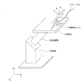
図2に示すように、角速度センサの校正装置は、支持部1によって回転自在に支持される回転装置2と、回転装置2に支持される検査台3と、を備える。
校正対象の角速度センサ4は検査台3に搭載され、検査台3と一体に回転するように固定される。角速度センサ4にはケーブル5が接続され、角速度センサ4で検出した角速度情報はケーブル5を介して外部に伝送されるとともに、後述の校正用信号はケーブル5を介して角速度センサ4に伝送される。
As shown in FIG. 2, the angular velocity sensor calibration apparatus includes a
The
ケーブル5の代わりに、スリップリングや無線伝送装置を用いて角速度情報を伝送してもよい。なお、図2において、角速度センサ4に記された黒丸は、角速度センサ4のピン端子のうち、1番目のピン(以後、1ピンともいう。)の位置を示す。
回転装置2は円柱状に形成され、回転装置2の長手方向の一端が支持部1によって回転自在に支持され、回転装置2の他端に検査台3が固定されている。検査台3は、板状を有し、検査台3の一方の面に校正対象の角速度センサ4を搭載するようになっており、回転装置2の回転軸が延びる方向と検査台3の角速度センサ4を搭載する側の面の法線方向とが傾きを持って回転装置2に固定される。なお、検査台3は、角速度センサ4を搭載する際には、角速度センサ4を搭載する側の面の法線方向と鉛直方向とが一致するように回転装置2により保持されている。
Instead of the cable 5, angular velocity information may be transmitted using a slip ring or a wireless transmission device. In FIG. 2, black circles marked on the
The
支持部1は回転装置2の駆動制御を行い、支持部1が回転装置2の長手方向の中心軸を回転軸として回転装置2を回転駆動することによって、検査台3が回転装置2の回転軸を軸として、右ねじの方向Aおよび右ねじとは逆の方向Bに回転し、その結果、検査台3に搭載された角速度センサ4が回転装置2の回転軸を軸として回転するようになっている。
角速度センサ4は、直交する3軸方向の角速度を検出する角速度センサである。
The
The
校正対象の角速度センサ4が検出可能な3軸方向をX軸、Y軸、Z軸とし、このX軸、Y軸、Z軸で定義されるXYZ3次元直交座標系を、角速度センサ4を基準とするXYZ座標系と定義する。
図2に示すように、回転装置2および検査台3は、検査台3に搭載された状態での、角速度センサ4を基準とするXYZ座標系において、そのX軸、Y軸及びZ軸の3軸の成分を有するベクトルPと平行な軸を回転軸として検査台3が回転するように配置される。
The three axis directions that can be detected by the
As shown in FIG. 2, the
つまり、回転装置2は、その回転軸がベクトルPと平行な軸となるように鉛直方向に対して傾きを持って支持部1により支持される。
なお、図2では、検査台3の角速度センサ4を搭載した面に対して垂直な方向をZ軸とし、Z軸と直交する、検査台3の角速度センサ4を搭載した面と平行な軸をX軸およびY軸としているが、これに限るものではなく、回転装置2を回転させたときに、角速度センサ4から3軸成分を得ることができれば、角速度センサ4を基準とするXYZ座標はどのように設定してもよい。
That is, the
In FIG. 2, the direction perpendicular to the surface of the inspection table 3 on which the
支持部1が回転装置2を回転駆動することによって、検査台3、つまり角速度センサ4が、角速度センサ4を基準とするXYZ直交座標系におけるX軸、Y軸、及びZ軸の3軸の成分を有するベクトルPと平行な軸を回転軸として回転する。
なお、支持部1は、回転装置2を駆動する場合には、予め設定した時間(例えば1秒間)に、所定の角度だけ回転させる。すなわち、検査台3を所定の角度だけ回転させる。
When the
In addition, when driving the
図2に示すような構成とすることにより、回転装置2は、X軸、Y軸、及びZ軸の3軸の成分を有するベクトルPを回転軸として、検査台3を回転させることができる。そして、ベクトルPは、検査台3に搭載された角速度センサ4を基準とするXYZ直交座標系における3軸の成分を有するベクトルである。そのため、回転装置2を駆動することによって、角速度センサ4は3軸の成分を検出し出力することになる。つまり、1軸(ベクトルPに平行な軸)周りの回転で角速度センサ4の3軸の成分をまとめて出力させることができ、すなわち3軸の感度調整を行なうことができることになる。
With the configuration as shown in FIG. 2, the
なお、図2では、角速度センサ4の3軸の成分をまとめて出力させる場合について説明したが、これに限るものではなく、2軸の成分をまとめて出力させることも可能である。
図3は、2軸の成分をまとめて出力させる場合の、角速度センサの校正装置の一例を示す斜視図である。
2軸の成分をまとめて出力させる場合には、図3に示すように、2つの回転軸を備えた、既存の角速度センサの校正装置を用いることができる。また、2つの回転軸を備えた既存の加速度センサの校正装置を同様に用いることができる。
In FIG. 2, the case where the three-axis components of the
FIG. 3 is a perspective view showing an example of a calibration device for an angular velocity sensor when biaxial components are output together.
When two-axis components are output together, an existing angular velocity sensor calibration device having two rotation axes can be used as shown in FIG. Further, an existing acceleration sensor calibration device having two rotation axes can be used in the same manner.
すなわち、図3に示す角速度センサの校正装置は、支持部1により回転自在に支持される回転装置2と、回転装置2に支持される検査台3と、を備えており、回転装置2は第1部材2aと、第1部材2aの外周に設けられる第2部材2bとを備える。第1部材2aは、円柱状に形成され、一端が支持部1に回転自在に支持され、鉛直方向をz軸としこのz軸と直交するx軸およびy軸を有するxyz直交座標系において、x軸を回転軸として回転する。第2部材2bは円柱状に形成され、一端が第1部材2aの外周に回転自在に支持され、鉛直方向をz軸とするxyz直交座標系におけるz軸と平行な軸を回転軸として回転する。そして、第2部材2bの他端に、第2部材2bの回転軸が検査台3に対して垂直となるように、すなわち検査台3が水平となるように固定される。
That is, the angular velocity sensor calibration apparatus shown in FIG. 3 includes a
角速度センサ4は、検査台3に搭載され、角速度センサ4と一体に回転するように固定されるが、このとき、角速度センサ4は、この角速度センサ4を基準とするXYZ直交座標系のZ軸が鉛直方向と一致し、且つ、X軸およびY軸が、鉛直方向をz軸とするxyz直交座標系のx軸およびy軸と一致しないように配置される。
なお、角速度センサ4は、水平面に載置したときの角速度センサ4の鉛直方向の検出軸がZ軸、Z軸と直交する水平方向をX軸およびY軸として直交する3次元座標系が角速度センサ4に設定されている。そのため、図3では、検査台3の角速度センサ4を搭載した面に対して垂直な方向が角速度センサ4の基準のXYZ直交座標系におけるZ軸となり、Z軸と直交する、検査台3の角速度センサ4を搭載した面と平行な軸がX軸およびY軸となっている。
The
The
このような構成において、支持部1は、回転装置2を、予め設定された時間(例えば1秒間)に所定の角度だけ回転駆動し、例えば、第1部材2aのみを回転させることによって、X軸成分とY軸成分とをまとめて出力させることができる。つまり、第1部材2aの回転軸はX軸であって、XYZ直交座標系におけるX軸は、角速度センサ4を基準とするxyz直交座標系のx軸とは異なる。そのため、第1部材2aをx軸周りに回転させたとき、角速度センサ4からはX軸成分とY軸成分とがまとめて出力されることになる。
In such a configuration, the
次に、第2部材2bのみを回転させる。XYZ直交座標系におけるZ軸は、角速度センサ4を基準とするxyz直交座標系のz軸と同じベクトルであるから、第2部材2bをz軸周りに回転させたとき、角速度センサ4からはZ軸成分を出力させることができる。したがって、2つの軸周りにそれぞれ検査台3を回転させることによって、3軸の成分を出力させることができる。このため、この3軸成分に基づいて角速度センサ4の感度の調整を行なうことができることになる。
Next, only the
次に、本発明の角速度センサの校正装置について説明する。
図4は、本発明に係る角速度センサの校正装置の一例を示す構成図である。
本発明に係る角速度センサの校正装置は、図4に示すように、図2に示す角速度センサの校正装置においてさらに、積算部6と感度調整部7とを備えている。積算部6および感度調整部7は、例えば、パーソナルコンピュータなどの演算処理装置により実現される。
Next, the angular velocity sensor calibration apparatus of the present invention will be described.
FIG. 4 is a configuration diagram showing an example of the calibration device for the angular velocity sensor according to the present invention.
As shown in FIG. 4, the angular velocity sensor calibration apparatus according to the present invention further includes an integrating unit 6 and a sensitivity adjustment unit 7 in the angular velocity sensor calibration apparatus shown in FIG. 2. The integration unit 6 and the sensitivity adjustment unit 7 are realized by an arithmetic processing device such as a personal computer, for example.
図4に示すように、支持部1により回転装置2を回転駆動することによって、回転装置2に固定された検査台3が回転装置2の回転軸を軸として回転し、その結果、検査台3に搭載された角速度センサ4が回転装置2の回転軸を軸として回転する。つまりベクトルPに平行な回転軸周りに回転する。
このとき、支持部1が、回転装置2を予め設定した時間(例えば1秒間)に所定の角度(例えば第1の角度)だけ回転させることによって、検査台3は、回転装置2の回転軸周りに第1の角度だけ回転する。
As shown in FIG. 4, when the
At this time, when the
検査台3の回転に伴い角速度センサ4も回転するため、角速度センサ4からは、角速度検出情報が出力される。このとき、角速度センサ4は、この角速度センサ4を基準とするXYZ直交座標系の3軸の成分を有するベクトルPに平行な軸周りに回転するため、角速度センサ4は、3軸の成分を検出し、その大きさに応じた角速度情報を出力する。角速度センサ4で検出された3軸の角速度情報は、ケーブル5を介して積算部6に入力される。
Since the
積算部6は、回転装置2が検査台3を第1の角度だけ回転させる間に角速度センサ4から出力される値を積算し積算結果を出力する。このとき、積算部6は、角速度センサ4から出力される、X、Y、Zの3軸の成分について検出軸毎に積算し、X軸成分の積算値、Y軸成分の積算値、Z軸成分の積算値を出力する。
感度調整部7は、積算部6から出力される、検査台3が第1の角度だけ回転したときの角速度センサ4の出力の積算値と予め設定した基準値とを比較し、この比較結果に基づいて角速度センサ4の感度調整を行なう。つまり、感度調整部7は、各軸成分の積算値毎に、それぞれ対応する基準値と比較し、比較結果に応じて検出軸毎に感度調整を行なう。なお、基準値は、予め設定された値であって、例えば校正装置の図示しない記憶部に予め格納しておいてもよく、或いは、校正を行なう際にユーザが、予め設定された基準値を入力するようにしてもよい。
The integrating unit 6 integrates the values output from the
The sensitivity adjusting unit 7 compares the integrated value of the output of the
例えば、感度調整部7では、積算値と基準値との比較結果に基づき感度調整用の校正用信号を検出軸毎に生成し、生成した校正用信号を、ケーブル5を介して角速度センサ4に送信する。角速度センサ4は、通知された校正用信号に応じて感度調整を行ない、以後、調整後の感度に応じた角速度情報を出力する。また、積算部6を介して感度調整部7に入力された、検査台3が第1の角度だけ回転したときの角速度センサ4の角速度情報或いはその積算値などは、例えば角速度センサ4のオフセット調整を行なう処理部など、後段の処理部に対して出力される。
For example, the sensitivity adjustment unit 7 generates a calibration signal for sensitivity adjustment for each detection axis based on the comparison result between the integrated value and the reference value, and sends the generated calibration signal to the
次に、本発明に係る角速度センサの校正方法を説明する。
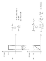
図5は、本発明に係る角速度センサの校正方法を説明するための図であって、図2に示した角度設定回転駆動方式による角速度センサの校正装置を駆動することにより、角速度センサ4から出力される矩形波を積分処理することによって、本発明の校正方法に用いる三角波を生成したものである。なお、図5は、角速度センサ4から出力される3軸成分のうち、1軸分の成分についての信号処理状況を示したものであり、実際には、図示した信号処理を、角速度センサ4から出力される3軸成分それぞれについて実行する。
Next, a method for calibrating the angular velocity sensor according to the present invention will be described.
FIG. 5 is a diagram for explaining a method of calibrating the angular velocity sensor according to the present invention, and outputs from the
図5において、(a)は角速度センサ4から出力される1軸分の矩形波であって、横軸は時間t、縦軸は角速度Ω〔dps〕である。(b)は角速度センサ4から出力された1軸分の矩形波を積算部6により積分して得られた三角波であって、横軸は時間t、縦軸は角度Θ〔deg〕である。
図5(a)に示すように、Vを角速度センサ4の出力(角速度情報)、Sを感度、Ωdcを角速度定数とすると、これら間には、次式(1)に示す関係がある。
V=S・Ωdc ……(1)
式(1)から、感度Sは次式(2)で表すことができる。
S=V/Ωdc ……(2)
In FIG. 5, (a) is a rectangular wave for one axis output from the
As shown in FIG. 5A, when V is the output of the angular velocity sensor 4 (angular velocity information), S is the sensitivity, and Ωdc is the angular velocity constant, there is a relationship represented by the following equation (1).
V = S · Ωdc (1)
From the equation (1), the sensitivity S can be expressed by the following equation (2).
S = V / Ωdc (2)
これに対して、本発明は、角速度センサ4の出力を積算していることから次式(3)の関係が成り立ち、その結果、感度Sは次式(4)で表すことができる。
∫Vdt=∫S・Ωdc・dt ……(3)
S=∫Vdt/∫Ωdc・dt
=∫Vdt/θ0≒Σ(V・Δt/θ0) ……(4)
なお、(4)式中のθ0は角度変化(angle variation)を示している。
On the other hand, since the present invention integrates the outputs of the
∫Vdt = ∫S · Ωdc · dt (3)
S = ∫Vdt / ∫Ωdc · dt
= ∫Vdt / θ0≈Σ (V · Δt / θ0) (4)
In addition, (theta) 0 in Formula (4) has shown angle change (angle variation).
積算部6は、角速度センサ4が出力する値の積算値として、三角波の頂点に相当する値を出力する。
そして、感度調整部7は、積算部6が出力する積算値と基準値とを比較する。ここで、基準値は、検査台3をXYZ座標の各回転軸周りに回転させる角度に対応した値である。この値は、角速度センサ4の設計時の出力代表値(Typ値)、つまり理想的な角速度センサ4を回転させたときに角速度センサ4が出力する値と同じである。感度調整部7は、X軸、Y軸、及びZ軸のそれぞれの軸周りに理想的な角速度センサ4を所定の角度だけ回転させたときの基準値と、各軸周りに角速度センサ4を回転させたときの角速度センサ4が出力する値を積算部6が積算した積算値と比較し、角速度センサ4の感度調整をする。
The integrating unit 6 outputs a value corresponding to the apex of the triangular wave as an integrated value of the values output from the
Then, the sensitivity adjustment unit 7 compares the integrated value output from the integrating unit 6 with a reference value. Here, the reference value is a value corresponding to an angle at which the inspection table 3 is rotated around each rotation axis of the XYZ coordinates. This value is the same as the output representative value (Typ value) at the time of designing the
感度調整部7は、X軸の成分の積算値がX軸回転に対応する基準値より大きいときは、角速度センサ4の感度が大きいため、感度が小さくなるように調整する。感度調整部7は、X軸の成分の積算値がX軸回転に対応する基準値より小さいときは、角速度センサ4の感度が小さいため、感度が大きくなるように調整する。Y軸及びZ軸についても、同様である。
When the integrated value of the X-axis component is larger than the reference value corresponding to the X-axis rotation, the sensitivity adjustment unit 7 adjusts the sensitivity so that the sensitivity is small because the sensitivity of the
なお、図3を用いて説明したように、角速度センサ4が出力する3軸成分のうち2軸成分のみをまとめて出力する場合には、まず、X軸周りに回転する第1部材2aのみを回転させる。これにより、角速度センサ4のX軸およびY軸成分をまとめて取得し、2軸についてのみ積算処理を行なう。次に、Z軸周りに回転する第2部材2bのみを回転させる。これにより、角速度センサ4のZ軸成分を取得し、Z軸についてのみ積算処理を行なう。そして、3軸の積算値と対応する基準値とを比較し、比較結果に基づいて感度調整用の校正用信号を生成する。
As described with reference to FIG. 3, when outputting only the two-axis component out of the three-axis components output from the
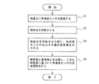
上記角速度センサの校正装置が行う角速度センサの校正方法をまとめると図6に示すフローチャートに示す処理手順となる。
すなわち、本発明に係る角速度センサの校正方法は、搭載ステップ(ステップS1)、回転ステップ(ステップS2)、積算ステップ(ステップS3)、および感度調整ステップ(ステップS4)を有する。
When the angular velocity sensor calibration method performed by the angular velocity sensor calibration apparatus is summarized, the processing procedure shown in the flowchart of FIG. 6 is obtained.
That is, the angular velocity sensor calibration method according to the present invention includes a mounting step (step S1), a rotation step (step S2), an integration step (step S3), and a sensitivity adjustment step (step S4).
まず、ステップS1では、検査台3に角速度センサ4を搭載する。この処理は、ユーザが手動で行なうようにしてもよく、また、図示しない搭載機構によって、角速度センサ4を自動的に搭載し、校正終了後は自動的に角速度センサ4を検査台3から取り除くようにしてもよい。
続いて、ステップS2では、XYZ直交座標系のX軸、Y軸、及びZ軸のうちの少なくとも2軸の成分を有するベクトルPを回転軸として、検査台3を所定の角度だけ回転させる。
First, in step S <b> 1, the
Subsequently, in step S2, the inspection table 3 is rotated by a predetermined angle with a vector P having at least two components of the X, Y, and Z axes of the XYZ orthogonal coordinate system as a rotation axis.
検査台3を回転させると、ステップS3に移行し、検査台3を回転させる間に角速度センサ4が出力する角速度情報の積算値を検出軸毎に演算し、検査台3が所定の角度だけ回転する間に角速度センサ4が出力した値の積算値を出力する。
そして、ステップS4では、検査台3が第1の角度だけ回転する間の角速度センサ4の出力の積算値と基準値とを比較し、この比較結果に基づいて、角速度センサの感度調整を行う。
When the inspection table 3 is rotated, the process proceeds to step S3, and an integrated value of angular velocity information output by the
In step S4, the integrated value of the output of the
以下、本発明の回転装置の動作および回転ステップ(ステップS2)について、詳細に説明する。なお、理解を容易にするために、角速度センサの1ピンの位置及び角速度センサ4の姿勢だけを図示して説明する。
Hereinafter, operation | movement and rotation step (step S2) of the rotating apparatus of this invention are demonstrated in detail. For ease of understanding, only the position of the
<実施形態1>
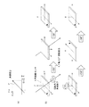
図7は、本発明に係る角速度センサの校正装置及び校正方法の実施形態1を説明するための説明図である。
実施形態1における角速度センサの校正装置は、角速度センサ4の2軸の出力をまとめて得るようにしたものである。
実施形態1は、図3に示す、2つの回転軸を備えた角速度センサの校正装置において、図7(a)に示すように、回転軸となるベクトルPが、角速度センサ4を基準とするXYZ直交座標系におけるX軸の成分及びY軸の成分を有し、Z軸の成分を有さない形態である。
<
FIG. 7 is an explanatory diagram for explaining the first embodiment of the calibration apparatus and the calibration method of the angular velocity sensor according to the present invention.
The angular velocity sensor calibration apparatus according to the first embodiment is configured to collectively obtain the biaxial outputs of the
In the calibration apparatus for the angular velocity sensor having two rotation axes shown in FIG. 3, the first embodiment is such that the vector P serving as the rotation axis is XYZ with reference to the
前述のように、回転装置2として角速度センサを校正するための既存の校正装置の回転装置と同じ構造のものを使用している。また、2つの回転軸を備えた既存の加速度センサの校正装置を同様に使用することもできる。
また、積算部6や感度調整部7の信号処理を簡易にするために、X軸の成分とY軸の成分の絶対値は等しい。つまり、回転軸となるベクトルPと平行な角速度ベクトルΩの大きさは、X軸の成分とY軸の成分の√2(2の平方根)倍の大きさである。
As described above, the
In order to simplify the signal processing of the integrating unit 6 and the sensitivity adjusting unit 7, the absolute values of the X-axis component and the Y-axis component are equal. That is, the magnitude of the angular velocity vector Ω parallel to the rotation axis vector P is √2 (square root of 2) times the X-axis component and the Y-axis component.
まず、支持部1は、回転装置2を回転駆動し、第1部材2aのみを回転させて図7(b)に示すように、上記ベクトルPを回転軸として、検査台3を+180度回転させる。このとき、角速度センサ4から右ねじの方向へ回したときのX軸の成分とY軸の成分とが出力される。つまり、検査台3を、約127度回転させた場合の出力相当のX軸成分およびY軸成分が出力されることになる。
First, the
この時点で、角速度センサ4の2軸分の出力が得られるため、2軸分の校正を行うことができる。つまり、角速度センサ4が2軸の角速度センサであれば、このステップだけで校正を行うことができることになる。
本実施形態では、3軸の角速度センサ4であるため、続いて、支持部1は、回転装置2を回転駆動し、上記ベクトルPを回転軸として、検査台3を−180度回転させる。このとき、角速度センサ4から右ねじとは逆の方向のX軸の成分とY軸の成分が出力される。
At this time, since the output for two axes of the
In the present embodiment, since it is the triaxial
次に、回転装置2は、Z軸を回転軸として、検査台3を+180度回転させる。このとき、角速度センサ4から右ねじの方向に回したときのZ軸の成分が出力される。最後に、回転装置は、Z軸を回転軸として、−180度回転させる。このとき、角速度センサ4から右ねじと逆の方向に回したときのZ軸の成分が出力される。
Next, the
このような回転動作により角速度センサから出力されたX軸の成分、Y軸の成分、Z軸の成分の各値は、積算部6によりそれぞれ積算され、各積算値が出力される。そして、感度調整部7が各軸成分の積算値と基準値とを比較し、角速度センサ4の感度を所望の感度に調整する。このとき、ベクトルPを回転軸として検査台3を+180度回転させたときまたは−180度回転させたときの角速度センサ4から出力される値の積算値、また、Z軸を回転軸として検査台3を+180度回転させたとき、または−180度回転させたときの角速度センサ4から出力される値の積算値をもとに、感度調整を行なってもよいし、ベクトルPを回転軸として検査台3を+180度回転させたときおよび−180度回転させたときそれぞれの角速度センサ4から出力される値の積算値と、Z軸を回転軸として検査台3を+180度および−180度回転させたときそれぞれの角速度センサ4から出力される値の積算値をもとに、感度調整を行なってもよい。
The values of the X-axis component, Y-axis component, and Z-axis component output from the angular velocity sensor by such a rotation operation are respectively integrated by the integrating unit 6, and each integrated value is output. Then, the sensitivity adjustment unit 7 compares the integrated value of each axis component with the reference value, and adjusts the sensitivity of the
このような構成及び動作により、実施形態1の角速度センサの校正装置及び校正方法では、正確な角速度で回転するターンテーブルを用いることなく、出荷前の角速度センサに対する各軸分の校正を終えるまでの時間を短くすることができる。つまり、角速度センサの出力値を積算し、この積算した値に基づいて校正を行なっているため、角速度センサの角速度を考慮する必要はない。したがって、正確な角速度で回転するターンテーブルを必要とはしない。また、ターンテーブルが安定した回転状態となるまで待機する必要はなく、さらに、上述のように2軸周りに回転させることで、角速度センサ4の3軸分の出力を得ることができるため、角速度センサ4の3軸分の出力を得るまでの所要時間を短縮することができ、結果的に、3軸分の校正に要する所要時間の短縮を図ることができる。
With such a configuration and operation, the angular velocity sensor calibration apparatus and calibration method according to the first embodiment can complete the calibration for each axis with respect to the angular velocity sensor before shipment without using a turntable that rotates at an accurate angular velocity. Time can be shortened. That is, since the output values of the angular velocity sensor are integrated and calibration is performed based on the integrated value, it is not necessary to consider the angular velocity of the angular velocity sensor. Therefore, it does not require a turntable that rotates at an accurate angular velocity. Further, it is not necessary to wait until the turntable is in a stable rotating state, and further, the output of the three angular axes of the
なお、実施形態1では、+180度の回転動作と−180度の回転動作を行っているが、絶対値は180度に限らず、0度より大きければよい。実施形態1では、180度であり、角速度センサ4の出力値が大きい。つまり、出力値のSNRが高くなり、基準値との比較誤差が小さくなるため、精度の良い感度調整を行うことができる。
さらに、実施形態1の角速度センサの校正装置及び校正方法は、上記ベクトルPを回転軸として、第1の角度(本例では、+180度)だけ検査台3を回転させ、さらに、上記ベクトルPを回転軸として、検査台3を第1の角度と符号が異なる第2の角度(本例では、−180度)だけ回転させているため、角速度センサ4の出力オフセットをキャンセルでき、ケーブルも絡まないという効果も奏する。
In the first embodiment, a +180 degree rotation operation and a -180 degree rotation operation are performed, but the absolute value is not limited to 180 degrees and may be larger than 0 degrees. In the first embodiment, it is 180 degrees and the output value of the
Furthermore, in the calibration apparatus and the calibration method for the angular velocity sensor according to the first embodiment, the inspection table 3 is rotated by the first angle (in this example, +180 degrees) with the vector P as the rotation axis, and the vector P is As the rotation axis, the inspection table 3 is rotated by a second angle (in this example, −180 degrees) different in sign from the first angle, so that the output offset of the
つまり、角速度センサ4の出力にオフセットを含む場合、例えば、第1の角度だけ検査台3を回転させた後、第1の角度と符号が異なる第2の角度だけ回転させると、角速度センサ4の出力は例えば図8(a)に示すような、オフセットを含む正値の矩形波と負値を含む矩形波となる。図8(a)において、横軸は時間、縦軸は角速度〔dps〕である。
図8(a)に示すようにオフセットを含む矩形波からオフセットを除去し、このオフセットを除去した矩形波を積分処理すると、図8(b)に示すような、正値の三角波と負値の三角波となる。図8(b)において、横軸は時間、縦軸は角速度センサ4の出力の積分値∫Vdtである。
That is, when the output of the
If the offset is removed from the rectangular wave including the offset as shown in FIG. 8A and the rectangular wave from which the offset is removed is integrated, a positive triangular wave and a negative value as shown in FIG. It becomes a triangular wave. In FIG. 8B, the horizontal axis represents time, and the vertical axis represents the integrated value ∫Vdt of the output of the
ここで、検査台3を正の角度である第1の角度プラスα°だけ回転させ、その後、負の角度である第2の角度−β°だけ回転させる場合、積算部6では、第1の角度だけ回転する間に角速度センサから出力される値の積算値を求めた後、第2の角度だけ回転する間に角速度センサから出力される値の積算値を求め、これら積算値の絶対値の和を、この回転に伴う積算値として出力する。また、支持部1は、検査台3を第1の角度プラスα°だけ回転させる時間と、第2の角度−β°だけ回転させる時間とが略等しくなるように回転駆動する。また、基準値は、第1の角度と第2の角度の和α°+β°の角度に相当する値に設定する。
Here, in the case where the examination table 3 is rotated by the first angle that is a positive angle plus α ° and then rotated by the second angle −β ° that is a negative angle, the integrating unit 6 uses the first angle. After obtaining the integrated value of the value output from the angular velocity sensor while rotating by the angle, the integrated value of the value output from the angular velocity sensor while rotating by the second angle is obtained, and the absolute value of these integrated values is obtained. The sum is output as an integrated value accompanying this rotation. The
このように検査台3を駆動した場合、検査台3を正の角度である+α°だけ回転させるのにかかる時間をT、検査台3を負の角度である−β°だけ回転させるのにかかる時間をTとしたとき、検査台3を正の角度である+α°だけ回転させる間にオフセット成分を持つ角速度センサから出力される値を積算した値は、α+(b×T)になる。検査台3を負の角度である−β°だけ回転させる間にオフセット成分を持つ角速度センサ4から出力される値を積算した値は−β+(b×T)になる。
When the inspection table 3 is driven in this way, the time required to rotate the inspection table 3 by a positive angle + α ° is T, and it takes time to rotate the inspection table 3 by a negative angle −β °. When time is T, a value obtained by integrating the values output from the angular velocity sensor having an offset component while the inspection table 3 is rotated by a positive angle + α ° is α + (b × T). A value obtained by integrating the values output from the
したがって、+α°だけ回転する間に角速度センサ4から出力される値を積算した値と、−β°だけ回転する間に角速度センサ4から出力される値を積算した値との差分は、(α+(b×T))−(−β+(b×T))=α+βになり、オフセット成分を消去することができる。なお、αとβとは同じ値であっても良いし、違う値であってもよい。
Accordingly, the difference between the value obtained by integrating the values output from the
<第2実施形態>
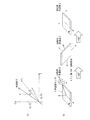
図9は、本発明に係る角速度センサの校正装置及び校正方法の実施形態2を説明するための説明図である。
実施形態2における角速度センサの校正装置は、角速度センサ4の3軸の出力をまとめて得るようにしたものである。
実施形態2は、図2に示す、角速度センサの校正装置において、図9(a)に示すように、回転軸となるベクトルPが、X軸の成分、Y軸の成分、及びZ軸の成分を有する形態である。また、積算部6や感度調整部7の信号処理を簡易にするために、X軸の成分、Y軸の成分、及びZ軸の成分の絶対値が等しくなるように回転軸を設定している。つまり、回転軸となるベクトルPと平行な角速度ベクトルΩの大きさは、X軸の成分、Y軸の成分、及びZ軸の成分の√3(3の平方根)倍の大きさである。
Second Embodiment
FIG. 9 is an explanatory diagram for explaining
The angular velocity sensor calibration apparatus according to the second embodiment is configured to collectively obtain the three-axis outputs of the
In the second embodiment, in the angular velocity sensor calibration apparatus shown in FIG. 2, as shown in FIG. 9A, the vector P serving as the rotation axis has an X-axis component, a Y-axis component, and a Z-axis component. It is a form which has. Further, in order to simplify the signal processing of the integrating unit 6 and the sensitivity adjusting unit 7, the rotation axis is set so that the absolute values of the X-axis component, the Y-axis component, and the Z-axis component are equal. . That is, the magnitude of the angular velocity vector Ω parallel to the rotation axis vector P is √3 (square root of 3) times the X-axis component, the Y-axis component, and the Z-axis component.
図9(b)に示すように、まず、支持部1は、回転装置2を回転駆動し、ベクトルPを回転軸として、検査台3を+180度回転させる。このとき、角速度センサ4から右ねじの方向へ回したときのX軸の成分、Y軸の成分、及びZ軸の成分が出力される。つまり、検査台3を約104度回転させた場合の出力相当のX軸成分、Y軸成分およびZ軸成分が出力されることになる。
As shown in FIG. 9B, first, the
この時点で、角速度センサ4の3軸分の出力が得られるため、この出力を用いることによって3軸分の校正を行うことができる。
本実施形態では、さらに、支持部1により回転装置2を回転駆動し、ベクトルPを回転軸として、検査台3を−180度回転させる。このとき、角速度センサ4から右ねじとは逆の方向のX軸の成分、Y軸の成分、及びZ軸の成分が出力される。
At this time, since the output for the three axes of the
In the present embodiment, the
このような回転動作により角速度センサ4から出力されたX軸の成分、Y軸の成分、Z軸の成分の各値は、積算部6によりそれぞれ積算され、各積算値が出力される。そして、感度調整部7が各軸成分の積算値と基準値とを比較し、角速度センサ4の感度を所望の感度に調整する。
このような構成及び動作により、実施形態2の角速度センサ4の校正装置及び校正方法においても、出荷前の角速度センサを正確な角速度で回転するターンテーブルを用いることなく校正することができ、角速度センサの各軸分の校正を終えるまでの時間を短くすることができる。
The values of the X-axis component, Y-axis component, and Z-axis component output from the
With this configuration and operation, the
なお、実施形態2では、+180度の回転動作と−180度の回転動作を行っているが、絶対値が180度に限らず、0度より大きければよい。実施形態2では、180度であり、角速度センサの出力値が大きい。つまり、出力値のSNRが高くなり、基準値との比較誤差が小さくなるため、精度の良い感度調整を行うことができる。
さらに、実施形態2の角速度センサの校正装置及び校正方法は、ベクトルPを回転軸として、第1の角度(本例では、+180度)だけ検査台3を回転させ、さらに、ベクトルPを回転軸として、検査台3を第1の角度と符号が異なる第2の角度(本例では、−180度)だけ回転させている。そのため、この場合も、上記実施形態1と同様の手順で、積算部6が第1の角度だけ回転させときの積算値と第2の角度だけ回転させたときの積算値との差分を演算しこれを積算値としてその基準値と比較することによって、角速度センサ4の出力オフセットをキャンセルでき、ケーブルが絡まないという効果も奏する。
In the second embodiment, the +180 degree rotation operation and the -180 degree rotation operation are performed. However, the absolute value is not limited to 180 degrees and may be larger than 0 degrees. In the second embodiment, it is 180 degrees, and the output value of the angular velocity sensor is large. That is, since the SNR of the output value is increased and the comparison error with the reference value is reduced, the sensitivity can be adjusted with high accuracy.
Furthermore, in the calibration apparatus and the calibration method for the angular velocity sensor according to the second embodiment, the inspection table 3 is rotated by the first angle (in this example, +180 degrees) with the vector P as the rotation axis, and the vector P is further rotated as the rotation axis. As described above, the inspection table 3 is rotated by a second angle (in this example, −180 degrees) different in sign from the first angle. Therefore, also in this case, the difference between the integrated value when the integrating unit 6 is rotated by the first angle and the integrated value when the integrating unit 6 is rotated by the second angle is calculated in the same procedure as in the first embodiment. By comparing this with the reference value as an integrated value, the output offset of the
なお、本発明の範囲は、図示され記載された例示的な実施形態に限定されるものではなく、本発明が目的とするものと均等な効果をもたらすすべての実施形態をも含む。さらに、本発明の範囲は、すべての開示されたそれぞれの特徴のうち特定の特徴のあらゆる所望する組み合わせによって画されうる。 It should be noted that the scope of the present invention is not limited to the illustrated and described exemplary embodiments, but includes all embodiments that provide the same effects as those intended by the present invention. Further, the scope of the invention can be defined by any desired combination of particular features among all the disclosed features.
1 支持部
2 回転装置
2a 第1部材
2b 第2部材
3 検査台
4 角速度センサ
5 ケーブル
6 積算部
7 感度調整部
DESCRIPTION OF
Claims (16)
前記検査台に搭載された角速度センサの検出軸を軸とするXYZ座標系における3つの軸のうち、少なくとも2つの軸の成分を有するベクトルの方向に延びる軸を回転軸として前記検査台を回転運動させる回転装置と、
前記検査台が所定の角度だけ前記回転運動を行なう間に前記角速度センサが出力する値の前記検出軸毎の積算値を出力する積算部と、
前記検出軸毎の積算値と予め設定された基準値とを比較し、当該比較結果に基づいて前記角速度センサの感度調整を行う感度調整部と、
を備えた角速度センサの校正装置。 An inspection table that can be equipped with an angular velocity sensor;
Of the three axes in the XYZ coordinate system having the detection axis of the angular velocity sensor mounted on the inspection table as an axis, the inspection table is rotated about an axis extending in the direction of a vector having at least two components. Rotating device to make
An integration unit for outputting an integrated value for each detection axis of a value output by the angular velocity sensor while the inspection table performs the rotational movement by a predetermined angle;
A sensitivity adjustment unit that compares the integrated value for each detection axis with a preset reference value and adjusts the sensitivity of the angular velocity sensor based on the comparison result;
Calibration device for angular velocity sensor comprising:
前記感度調整部は、前記検査台が前記第1の角度だけ回転したときの前記積算部から出力される積算値と前記検査台が前記第2の角度だけ回転したときの前記積算部から出力される積算値と前記基準値とに基づいて、前記角速度センサの感度調整を行なう請求項1に記載の角速度センサの校正装置。 The rotating device rotates the inspection table around the rotation axis by a first angle in one direction, and then rotates the inspection table by a second angle in the opposite direction,
The sensitivity adjustment unit is output from the integration value output from the integration unit when the inspection table is rotated by the first angle and from the integration unit when the inspection table is rotated by the second angle. The angular velocity sensor calibration apparatus according to claim 1, wherein sensitivity adjustment of the angular velocity sensor is performed based on the integrated value and the reference value.
絶対値が0度よりも大きく180度以下である請求項2に記載の角速度センサの校正装置。 The first angle is:
The angular velocity sensor calibration apparatus according to claim 2, wherein the absolute value is greater than 0 degrees and equal to or less than 180 degrees.
絶対値が180度である請求項3に記載の角速度センサの校正装置。 The first angle is:
4. The angular velocity sensor calibration apparatus according to claim 3, wherein the absolute value is 180 degrees.
絶対値が0度よりも大きく180度以下である請求項2から請求項4のいずれか1項に記載の角速度センサの校正装置。 The second angle is:
The angular velocity sensor calibration apparatus according to any one of claims 2 to 4, wherein an absolute value is greater than 0 degrees and equal to or less than 180 degrees.
絶対値が180度である請求項5に記載の角速度センサの校正装置。 The second angle is:
6. The angular velocity sensor calibration apparatus according to claim 5, wherein the absolute value is 180 degrees.
前記XYZ座標系におけるX軸の成分、Y軸の成分、及びZ軸の成分を有し、
これら軸成分の絶対値がそれぞれ等しい請求項1から請求項6のいずれか1項に記載の角速度センサの校正装置。 The vector is
Having an X-axis component, a Y-axis component, and a Z-axis component in the XYZ coordinate system;
The angular velocity sensor calibration apparatus according to any one of claims 1 to 6, wherein absolute values of these axial components are equal to each other.
前記XYZ座標系におけるZ軸の成分を除く、X軸の成分とY軸の成分とを有し、
前記X軸の成分及び前記Y軸の成分の絶対値がそれぞれ等しい請求項1から請求項6のいずれか1項に記載の角速度センサの校正装置。 The vector is
An X-axis component and a Y-axis component excluding the Z-axis component in the XYZ coordinate system;
The angular velocity sensor calibration apparatus according to any one of claims 1 to 6, wherein absolute values of the X-axis component and the Y-axis component are equal to each other.
前記回転軸周りに前記検査台を所定の角度だけ回転運動させる回転ステップと、
前記検査台が前記回転運動を行なう間に、前記角速度センサが出力する値の前記検出軸毎の積算値を出力する積算ステップと、
前記検出軸毎の積算値と予め設定された基準値とを比較し、当該比較結果に基づいて前記角速度センサの感度調整を行う調整ステップと、
を有する角速度センサの校正方法。 Of the three axes in the XYZ coordinate system having the detection axis of the angular velocity sensor as an axis, the axis extending in the direction of a vector having at least two axis components coincides with the rotation axis of the rotating device that rotates the examination table. And mounting step of mounting the angular velocity sensor on the inspection table;
A rotation step of rotating the inspection table by a predetermined angle around the rotation axis;
An integration step of outputting an integrated value for each detection axis of a value output by the angular velocity sensor while the inspection table performs the rotational movement;
An adjustment step of comparing the integrated value for each detection axis with a preset reference value and adjusting the sensitivity of the angular velocity sensor based on the comparison result;
Calibration method of angular velocity sensor having
前記検査台を前記回転軸周りに一方向に第1の角度だけ回転させた後に、逆方向に第2の角度だけ回転させるステップであり、
前記積算ステップは、前記検査台が前記第1の角度だけ回転運動する間に前記角速度センサから出力される値の検出軸毎の積算値と、前記検査台が前記第2の角度だけ回転運動する間に前記角速度センサから出力される値の検出軸毎の積算値とを出力するステップである請求項9に記載の角速度センサの校正方法。 The rotation step includes
Rotating the inspection table around the rotation axis by a first angle in one direction and then rotating the inspection table by a second angle in the opposite direction;
The integrating step includes an integrated value for each detection axis of a value output from the angular velocity sensor while the inspection table rotates by the first angle, and the inspection table rotates by the second angle. 10. The method of calibrating an angular velocity sensor according to claim 9, wherein the method is a step of outputting an integrated value for each detection axis of a value output from the angular velocity sensor.
絶対値が0度よりも大きく180度以下である請求項10に記載の角速度センサの校正方法。 The first angle is:
The method of calibrating an angular velocity sensor according to claim 10, wherein the absolute value is greater than 0 degree and equal to or less than 180 degrees.
絶対値が180度である請求項11に記載の角速度センサの校正方法。 The first angle is:
The method of calibrating an angular velocity sensor according to claim 11, wherein the absolute value is 180 degrees.
絶対値が0度よりも大きく180度以下である請求項10から請求項12のいずれか1項に記載の角速度センサの校正方法。 The second angle is:
The method of calibrating an angular velocity sensor according to any one of claims 10 to 12, wherein an absolute value is greater than 0 degrees and equal to or less than 180 degrees.
絶対値が180度である請求項13に記載の角速度センサの校正方法。 The second angle is:
The method of calibrating an angular velocity sensor according to claim 13, wherein the absolute value is 180 degrees.
前記XYZ座標系における、X軸の成分、Y軸の成分、及びZ軸の成分を有し、これら軸成分の絶対値がそれぞれ等しい請求項9から請求項14のいずれか1項に記載の角速度センサの校正方法。 The vector is
The angular velocity according to any one of claims 9 to 14, which has an X-axis component, a Y-axis component, and a Z-axis component in the XYZ coordinate system, and the absolute values of these axis components are equal to each other. Sensor calibration method.
前記XYZ座標系における、Z軸の成分を除く、X軸の成分及びY軸の成分を有し、前記X軸の成分及び前記Y軸の成分の絶対値がそれぞれ等しい請求項9から請求項14のいずれか1項に記載の角速度センサの校正方法。 The vector is
The X-axis component and the Y-axis component excluding the Z-axis component in the XYZ coordinate system, and the absolute values of the X-axis component and the Y-axis component are equal to each other. The angular velocity sensor calibration method according to any one of the above.
Priority Applications (1)
| Application Number | Priority Date | Filing Date | Title |
|---|---|---|---|
| JP2013258443A JP2015114286A (en) | 2013-12-13 | 2013-12-13 | Angular velocity sensor calibration apparatus and calibration method thereof |
Applications Claiming Priority (1)
| Application Number | Priority Date | Filing Date | Title |
|---|---|---|---|
| JP2013258443A JP2015114286A (en) | 2013-12-13 | 2013-12-13 | Angular velocity sensor calibration apparatus and calibration method thereof |
Publications (1)
| Publication Number | Publication Date |
|---|---|
| JP2015114286A true JP2015114286A (en) | 2015-06-22 |
Family
ID=53528196
Family Applications (1)
| Application Number | Title | Priority Date | Filing Date |
|---|---|---|---|
| JP2013258443A Pending JP2015114286A (en) | 2013-12-13 | 2013-12-13 | Angular velocity sensor calibration apparatus and calibration method thereof |
Country Status (1)
| Country | Link |
|---|---|
| JP (1) | JP2015114286A (en) |
Cited By (2)
| Publication number | Priority date | Publication date | Assignee | Title |
|---|---|---|---|---|
| CN113215880A (en) * | 2021-04-22 | 2021-08-06 | 中国安全生产科学研究院 | Device and method for monitoring irregular settlement on two sides of subway rail |
| JP2023101310A (en) * | 2022-01-07 | 2023-07-20 | 大成建設株式会社 | Calculation method of calibration value |
Citations (3)
| Publication number | Priority date | Publication date | Assignee | Title |
|---|---|---|---|---|
| JPS6117619U (en) * | 1984-07-05 | 1986-02-01 | 三菱重工業株式会社 | gyro calibration device |
| JPH02266213A (en) * | 1989-04-06 | 1990-10-31 | Nec Home Electron Ltd | Vibration gyro device |
| WO2011083511A1 (en) * | 2010-01-07 | 2011-07-14 | パイオニア株式会社 | Method of inspecting angular velocity sensor and apparatus for inspecting angular velocity sensor |
-
2013
- 2013-12-13 JP JP2013258443A patent/JP2015114286A/en active Pending
Patent Citations (3)
| Publication number | Priority date | Publication date | Assignee | Title |
|---|---|---|---|---|
| JPS6117619U (en) * | 1984-07-05 | 1986-02-01 | 三菱重工業株式会社 | gyro calibration device |
| JPH02266213A (en) * | 1989-04-06 | 1990-10-31 | Nec Home Electron Ltd | Vibration gyro device |
| WO2011083511A1 (en) * | 2010-01-07 | 2011-07-14 | パイオニア株式会社 | Method of inspecting angular velocity sensor and apparatus for inspecting angular velocity sensor |
Cited By (4)
| Publication number | Priority date | Publication date | Assignee | Title |
|---|---|---|---|---|
| CN113215880A (en) * | 2021-04-22 | 2021-08-06 | 中国安全生产科学研究院 | Device and method for monitoring irregular settlement on two sides of subway rail |
| CN113215880B (en) * | 2021-04-22 | 2021-12-03 | 中国安全生产科学研究院 | Device and method for monitoring irregular settlement on two sides of subway rail |
| JP2023101310A (en) * | 2022-01-07 | 2023-07-20 | 大成建設株式会社 | Calculation method of calibration value |
| JP7684234B2 (en) | 2022-01-07 | 2025-05-27 | 大成建設株式会社 | Calibration value calculation method |
Similar Documents
| Publication | Publication Date | Title |
|---|---|---|
| US9689678B2 (en) | MEMS balanced inertial angular sensor and method for balancing such a sensor | |
| JP6363638B2 (en) | Vibrating mass gyroscope system and method | |
| JP5043358B2 (en) | Inclination angle calculation method and inclination angle calculation device | |
| WO2005095998A1 (en) | Method of measuring lateral sensitivity of sensor for detecting acceleration, and acceleration measuring method | |
| CN109459585B (en) | An accelerometer zero offset correction method | |
| EP2280264B1 (en) | Standard exciter | |
| CN106017839A (en) | Bending and torsional vibration detection control apparatus and method based on flexible articulated slab | |
| CN105628976B (en) | MEMS acceleration transducers performance parameter calibration method, processor and system | |
| CN110631605B (en) | Gyro array calibration method and system | |
| EP3315917B1 (en) | Microelectromechanical systems device test system and method | |
| CN103323625A (en) | Error calibration compensation method of accelerometers in MEMS-IMU under dynamic environment | |
| US9500669B2 (en) | System and method for calibrating an inertial sensor | |
| JP2014139561A (en) | Angular velocity sensor calibration device and calibration method for the same | |
| CN108398576B (en) | Static error calibration system and method | |
| JP2015114286A (en) | Angular velocity sensor calibration apparatus and calibration method thereof | |
| JP5697149B2 (en) | Acceleration sensor characteristic evaluation method and program | |
| KR102143462B1 (en) | Ahrs sensor and apparatus and method for compensating bias and scale error thereof | |
| WO2011083511A1 (en) | Method of inspecting angular velocity sensor and apparatus for inspecting angular velocity sensor | |
| Dumont et al. | Rotational accelerometers and their usage in investigating shaker head rotations | |
| CN115135962B (en) | Method and apparatus for zero-g offset calibration of MEMS-based accelerometers | |
| JP5688842B2 (en) | Magnetic field measurement adjustment device | |
| JP2015114285A (en) | Calibration device and calibration method of angular velocity sensor | |
| CN105866473A (en) | Motor vibration acceleration measurement method and apparatus thereof | |
| CN217058838U (en) | Multi-axis integrated micro-electro-mechanical system inertia device testing device and system | |
| JP4972568B2 (en) | Magnetic field measuring apparatus and magnetic field measurement value correction method |
Legal Events
| Date | Code | Title | Description |
|---|---|---|---|
| A621 | Written request for application examination |
Free format text: JAPANESE INTERMEDIATE CODE: A621 Effective date: 20160908 |
|
| A977 | Report on retrieval |
Free format text: JAPANESE INTERMEDIATE CODE: A971007 Effective date: 20170607 |
|
| A131 | Notification of reasons for refusal |
Free format text: JAPANESE INTERMEDIATE CODE: A131 Effective date: 20170704 |
|
| A02 | Decision of refusal |
Free format text: JAPANESE INTERMEDIATE CODE: A02 Effective date: 20180109 |