JP2015114283A - Electronic apparatus, method of controlling electronic apparatus, and control program of electronic apparatus - Google Patents
Electronic apparatus, method of controlling electronic apparatus, and control program of electronic apparatus Download PDFInfo
- Publication number
- JP2015114283A JP2015114283A JP2013258393A JP2013258393A JP2015114283A JP 2015114283 A JP2015114283 A JP 2015114283A JP 2013258393 A JP2013258393 A JP 2013258393A JP 2013258393 A JP2013258393 A JP 2013258393A JP 2015114283 A JP2015114283 A JP 2015114283A
- Authority
- JP
- Japan
- Prior art keywords
- piezoelectric element
- control unit
- electronic device
- detection
- detection sensitivity
- Prior art date
- Legal status (The legal status is an assumption and is not a legal conclusion. Google has not performed a legal analysis and makes no representation as to the accuracy of the status listed.)
- Pending
Links
- 238000000034 method Methods 0.000 title claims description 34
- 238000001514 detection method Methods 0.000 claims abstract description 258
- 230000035945 sensitivity Effects 0.000 claims abstract description 124
- 230000001133 acceleration Effects 0.000 claims description 16
- 238000005259 measurement Methods 0.000 claims description 7
- 230000004044 response Effects 0.000 claims description 3
- 239000011521 glass Substances 0.000 description 17
- 238000012545 processing Methods 0.000 description 8
- 238000010586 diagram Methods 0.000 description 7
- 230000006870 function Effects 0.000 description 7
- 230000033001 locomotion Effects 0.000 description 5
- 230000005540 biological transmission Effects 0.000 description 4
- 238000004891 communication Methods 0.000 description 4
- 230000010355 oscillation Effects 0.000 description 4
- 239000000758 substrate Substances 0.000 description 4
- 230000007257 malfunction Effects 0.000 description 3
- 230000000694 effects Effects 0.000 description 2
- 239000011347 resin Substances 0.000 description 2
- 229920005989 resin Polymers 0.000 description 2
- 238000006243 chemical reaction Methods 0.000 description 1
- 238000002474 experimental method Methods 0.000 description 1
- 239000004973 liquid crystal related substance Substances 0.000 description 1
- 239000000463 material Substances 0.000 description 1
- 239000002184 metal Substances 0.000 description 1
- 239000000203 mixture Substances 0.000 description 1
- 230000002093 peripheral effect Effects 0.000 description 1
- 238000010079 rubber tapping Methods 0.000 description 1
- 230000035939 shock Effects 0.000 description 1
- 210000000707 wrist Anatomy 0.000 description 1
Images
Landscapes
- Electric Clocks (AREA)
- Measurement Of Unknown Time Intervals (AREA)
Abstract
Description
本発明は、電子機器、電子機器の制御方法、および電子機器の制御プログラムに関する。 The present invention relates to an electronic device, an electronic device control method, and an electronic device control program.
電子時計において、利用者によって与えられた衝撃を検出してスイッチ信号として用いることが提案されている。このような電子時計では、ブザー音などを出力するために用いられている圧電素子が電子時計のケースに取り付けられている。電子時計のケースに取り付けられている圧電素子は、ケースを叩かれた場合、圧電素子に歪みが加わることで圧電効果を生じ、電圧を発生することが知られている。 In an electronic timepiece, it has been proposed to detect an impact given by a user and use it as a switch signal. In such an electronic timepiece, a piezoelectric element used for outputting a buzzer sound or the like is attached to the case of the electronic timepiece. It is known that a piezoelectric element attached to a case of an electronic timepiece generates a voltage by generating a piezoelectric effect by applying strain to the piezoelectric element when the case is hit.
例えば、特許文献1及び特許文献2には、電子機器の表面を利用者が叩いたことを圧電素子に発生する信号に応じて検出することが提案されている。特許文献1の技術では、ピエゾ素子(圧電素子)を搭載した電子機器に、外部から衝撃を受けたときにピエゾ素子から発生する電気的衝撃信号を出力するモニター電極を設け、モニター電極から電気的衝撃信号を出力すると共に、出力した電気的衝撃信号を電気的制御信号に変換する電気的制御信号変換回路を設けることで、衝撃を与えた際にピエゾ素子に生じる起電力を、各機能の動作を制御するために出力できるようにすることが提案されている。 For example, Patent Document 1 and Patent Document 2 propose that a user hitting the surface of an electronic device is detected according to a signal generated in a piezoelectric element. In the technique of Patent Document 1, a monitor electrode that outputs an electrical shock signal generated from a piezo element when an external impact is applied to an electronic device equipped with a piezo element (piezoelectric element) is provided. By providing an electrical control signal conversion circuit that outputs an impact signal and converts the output electrical impact signal into an electrical control signal, the electromotive force generated in the piezo element when an impact is applied is It has been proposed to be able to output to control.
また、特許文献2に記載の技術では、2つのタイマーを有し、利用者の意図に反しスイッチが作動しないように、2つのタイマーを利用し誤動作を防止することが提案されている。第1タイマーはON信号の持続時間を規定し、弱い信号や短い信号を除去する。第2タイマーはスイッチ入力後、信号を受け付けないマスク時間を設け、強い信号などで複数の信号が連続して入ることを防止する。 Further, in the technique described in Patent Document 2, it is proposed to have two timers and prevent malfunctions by using the two timers so that the switch does not operate against the user's intention. The first timer defines the duration of the ON signal and removes weak signals and short signals. The second timer provides a mask time during which no signal is received after the switch is input, and prevents a plurality of signals from entering continuously with a strong signal or the like.
上述のように、圧電素子から発生する信号により、電子機器の表面を利用者が叩いたことを検出して各種の動作を行わせるようにした場合、利用者の腕の動きにより、誤検出が生じる可能性がある。特に、利用者が電子時計を装着してランニングをしているような場合には、利用者の腕の動きによる振動が電子時計に伝わり、圧電素子から検出信号が発生し、使用者の意図に反して、動作が設定される可能性が高い。 As described above, when a user hits the surface of an electronic device based on a signal generated from a piezoelectric element to perform various operations, erroneous detection may occur due to the movement of the user's arm. It can happen. In particular, when a user is wearing an electronic timepiece and running, vibration due to the movement of the user's arm is transmitted to the electronic timepiece, and a detection signal is generated from the piezoelectric element. On the other hand, there is a high possibility that the operation is set.
利用者の腕の動きによる振動により圧電素子から検出信号が発生しないように、圧電素子の検出感度を下げることが考えられる。しかしながら、圧電素子の検出感度を下げると、電子機器の表面を強く叩かなければ入力が検出できなくなり、操作性が悪化する。利用者が感度設定を行う場合、操作性に影響を与えず、且つ誤動作が生じない感度に設定するのは、困難である。 It is conceivable to reduce the detection sensitivity of the piezoelectric element so that a detection signal is not generated from the piezoelectric element due to vibration caused by the movement of the user's arm. However, when the detection sensitivity of the piezoelectric element is lowered, the input cannot be detected unless the surface of the electronic device is strongly hit, and the operability is deteriorated. When the user performs sensitivity setting, it is difficult to set the sensitivity so as not to affect operability and to cause no malfunction.
特許文献1および特許文献2には、このような誤検出を防止するために、圧電素子の検出信号を、フィルタ回路を介して出力させることが記載されている。しかしながら、このようなフィルタ回路を設けると、回路規模が増大する。また、特許文献2には、2つのタイマーを利用して、このような誤動作を防止することが記載されている。しかしながら、特許文献2の構成では、多数のタイマー回路やゲート回路が必要であり、回路が複雑化する。 Patent Document 1 and Patent Document 2 describe that a detection signal of a piezoelectric element is output via a filter circuit in order to prevent such erroneous detection. However, when such a filter circuit is provided, the circuit scale increases. Patent Document 2 describes that two malfunctions are prevented by using two timers. However, the configuration of Patent Document 2 requires a large number of timer circuits and gate circuits, which complicates the circuit.
本発明は、上記の事情に鑑み成されたものであって、圧電素子による入力を行う際に、利用者の腕振り等による誤検出を防止できるようにした電子機器、および電子機器の制御方法を提供することを目的としている。 The present invention has been made in view of the above circumstances, and an electronic device capable of preventing erroneous detection due to a user's arm swing or the like when inputting by a piezoelectric element, and a method of controlling the electronic device The purpose is to provide.
上記目的を達成するため、本発明の一態様に係る電子機器は、自電子機器本体の一部に固定された圧電素子と、前記圧電素子が外部から受けた衝撃に応じて発生した起電圧に対するゲインを切り替えることにより、前記圧電素子の検出感度を切り替えるゲイン切替部と、歩行又は走行を表す情報を判定し、前記歩行又は走行を表す情報に基づいて、前記圧電素子の検出感度を切り替える制御部と、を備えることを特徴とする。 In order to achieve the above object, an electronic device according to one embodiment of the present invention is provided with a piezoelectric element fixed to a part of a main body of the electronic device and an electromotive voltage generated in response to an impact received by the piezoelectric element from the outside. A gain switching unit that switches the detection sensitivity of the piezoelectric element by switching the gain, and a control unit that determines information representing walking or running and switches the detection sensitivity of the piezoelectric element based on the information representing walking or running And.
また、本発明の一態様に係る電子機器において、前記歩行又は走行を表す情報は動作モードであり、前記制御部は、設定された動作モードを判定し、前記設定された動作モードに基づいて、前記圧電素子の検出感度を切り替えるようにしてもよい。 Further, in the electronic device according to one aspect of the present invention, the information representing the walking or running is an operation mode, and the control unit determines a set operation mode, and based on the set operation mode, You may make it switch the detection sensitivity of the said piezoelectric element.
また、本発明の一態様に係る電子機器において、前記動作モードは、ストップウォッチ計測に関連するモードであり、前記制御部は、設定モードが前記ストップウォッチ計測に関連するモードである場合には、前記圧電素子の検出感度を下げるように制御するようにしてもよい。 Further, in the electronic device according to an aspect of the present invention, the operation mode is a mode related to stopwatch measurement, and the control unit, when the setting mode is a mode related to the stopwatch measurement, You may make it control so that the detection sensitivity of the said piezoelectric element may be lowered | hung.
また、本発明の一態様に係る電子機器において、自電子機器に加わる加速度を検出する加速度センサを備え、前記動作モードは、前記加速度センサによって検出された結果に基づくモードであり、前記制御部は、前記加速度センサによって検出された結果に基づくモードに応じて、前記圧電素子の検出感度を切り替えるようにしてもよい。 The electronic device according to one aspect of the present invention includes an acceleration sensor that detects acceleration applied to the electronic device, wherein the operation mode is a mode based on a result detected by the acceleration sensor, and the control unit The detection sensitivity of the piezoelectric element may be switched according to a mode based on the result detected by the acceleration sensor.
また、本発明の一態様に係る電子機器において、前記歩行又は走行を表す情報は所定時間内での圧電素子の検出信号の数であり、前記制御部は、前記所定時間内での圧電素子の検出信号をカウントし、前記所定時間内での圧電素子の検出信号の数に基づいて、前記圧電素子の検出感度を切り替えるようにしてもよい。 In the electronic device according to one aspect of the present invention, the information indicating the walking or running is the number of detection signals of the piezoelectric element within a predetermined time, and the control unit is configured to detect the piezoelectric element within the predetermined time. The detection signal may be counted, and the detection sensitivity of the piezoelectric element may be switched based on the number of detection signals of the piezoelectric element within the predetermined time.
また、本発明の一態様に係る電子機器において、前記制御部は、前記所定時間内での圧電素子の検出信号の数が第1の所定数に達した場合には、前記圧電素子の検出感度を下げるように制御するようにしてもよい。 In the electronic device according to one aspect of the present invention, the control unit may detect the detection sensitivity of the piezoelectric element when the number of detection signals of the piezoelectric element within the predetermined time reaches a first predetermined number. You may make it control to lower.
また、本発明の一態様に係る電子機器において、前記制御部は、前記所定時間内での圧電素子の検出信号の数が第2の所定数以下である場合には、前記圧電素子の検出感度を上げるように制御するようにしてもよい。 In the electronic device according to one aspect of the present invention, the control unit may detect the sensitivity of the piezoelectric element when the number of detection signals of the piezoelectric element within the predetermined time is equal to or less than a second predetermined number. You may make it control so that it may raise.
上記目的を達成するため、本発明の一態様に係る電子機器の制御方法は、自電子機器本体の一部に圧電素子が固定された電子機器の制御方法であって、歩行又は走行を表す情報を判定する判定手順と、前記歩行又は走行を表す情報に基づいて、圧電素子の検出感度を切り替える制御手順と、を含むことを特徴とする。 In order to achieve the above object, a method for controlling an electronic device according to one aspect of the present invention is a method for controlling an electronic device in which a piezoelectric element is fixed to a part of the body of the electronic device, and represents information indicating walking or running. And a control procedure for switching the detection sensitivity of the piezoelectric element based on the information indicating the walking or running.
上記目的を達成するため、本発明の一態様に係る電子機器の制御プログラムは、自電子機器本体の一部に圧電素子が固定された電子機器の制御プログラムであって、歩行又は走行を表す情報を判定するステップと、前記歩行又は走行を表す情報に基づいて、圧電素子の検出感度を切り替えるステップと、を含むことを特徴とする。 In order to achieve the above object, a control program for an electronic device according to an aspect of the present invention is a control program for an electronic device in which a piezoelectric element is fixed to a part of the body of the electronic device, and represents information indicating walking or running. And a step of switching the detection sensitivity of the piezoelectric element based on the information indicating the walking or running.
本発明によれば、最適な検出感度で、圧電素子からの検出信号を検出でき、利用者の腕振り等による誤検出を防止できる。 According to the present invention, a detection signal from a piezoelectric element can be detected with an optimum detection sensitivity, and erroneous detection due to a user's arm swing or the like can be prevented.
[第1実施形態]
以下、本発明の実施の形態について図面を参照しながら説明する。また、以下の例では、電子機器の一例として、電子時計を例に説明する。
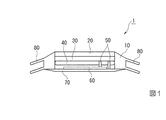
図1は、本実施形態に係る電子時計1の概略断面図である。図1に示すように、電子時計1は、ケース10、ガラス20、基盤30、電池40、電極50、圧電素子60、裏蓋70、およびベルト80を備えている。
[First Embodiment]
Hereinafter, embodiments of the present invention will be described with reference to the drawings. In the following example, an electronic timepiece will be described as an example of an electronic device.
FIG. 1 is a schematic cross-sectional view of an electronic timepiece 1 according to the present embodiment. As shown in FIG. 1, the electronic timepiece 1 includes a
ケース10の内部には、基盤30、電池40、電極50、および圧電素子60が組み込まれている。ケース10には、ガラス20、裏蓋70、およびベルト80が取り付けられている。ケース10は、例えば樹脂またはゴムであり、ガラス20より柔らかい素材である。
A
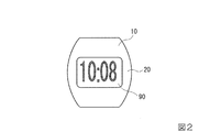
ガラス20は、基盤30の上に取り付けられている。ガラス20は、図2に示すように、表示部90を保護している。図2は、本実施形態に係る電子時計の概略上面図である。表示部90は、時刻、動作モード、ストップウォッチの計測時間、ラップデータ、タイマー時刻等を表示する表示部である。表示部90は、一例として液晶表示装置(LCD)である。
The
基盤30には、図3を用いて後述する電気回路が取り付けられている。また、基盤30には、電池40から電力が供給されている。
電池40は、基盤30の各回路、圧電素子60に電極50を介して電力を供給する。電池40は、一例としてボタン型電池である。
電極50は、電池40からの電力を基盤30および圧電素子60に供給する。
An electrical circuit described later with reference to FIG. 3 is attached to the
The
The
圧電素子60は、裏蓋70に固着されている。圧電素子60は、基盤30の制御部102の制御に応じて、時報等の報知音を発する。また、圧電素子60は、ケース10およびガラス20に加えられた衝撃により発生した信号を、基盤30の検出部に出力する。
裏蓋70は、電子時計1の裏面を保護する蓋である。裏蓋70は、圧電素子60が報知音を発するときに、共振部の役割を果たす。裏蓋70は、一例として樹脂、金属である。
ベルト80は、利用者の手首(腕)に装着されるために使用される。
電極50は、電池40の電力を基盤30および圧電素子60に供給する。
The
The
The
The
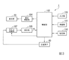
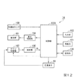
図3は、本実施形態に係る電子時計1の構成を示したブロック図である。図3に示すように、電子時計1は、発振部101、制御部102、入力部103、表示制御部104、圧電素子60、表示部90、検出部105、ゲイン切替部107、および記憶部106を備える。
FIG. 3 is a block diagram showing a configuration of the electronic timepiece 1 according to the present embodiment. As shown in FIG. 3, the electronic timepiece 1 includes an
発振部101は、制御部102の動作用の基準クロック信号を発生させ、発生させた基準クロック信号を制御部102に出力する。なお、発振部101が生成した基準クロック信号は、時計動作、タイマー動作、ストップウォッチ計時動作等に使用される。
制御部102は、入力部103および検出部105から入力された検出結果に応じて、電子時計1の動作モードの切り替え、各動作モードにおける動作の選択を行う。制御部102は、各動作モードの制御に応じて、及び電子時計1を構成する各電子回路要素の制御等を行う。
The
The
入力部103は、利用者からの操作による入力を受け付けるボタンを含み、利用者からの指示の入力を検出し、検出した検出結果を制御部102に出力する。
表示制御部104は、制御部102からの制御信号に応じて、表示部90にストップウォッチ計時時刻、タイマー計時時刻、及び時刻等を表示させる。
The
The
ゲイン切替部107は、圧電素子60から入力された信号を増幅して、検出部105に出力する。ゲイン切替部107のゲインは、制御部102からの制御信号により、切り替え可能とされている。
The
検出部105は、ゲイン切替部107を介して、圧電素子60から入力された信号を検出し、検出した検出結果を制御部102に出力する。
The
記憶部106には、制御部102が実行するプログラム、タイマー設定情報等が記憶されている。ここで、タイマー設定情報とは、タイマーが計時するタイマー時刻である。記憶部106は、例えばRAM(ランダム・アクセス・メモリ)である。
The
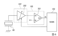
図4は、本実施形態に係るゲイン切替部107および検出部105の構成例を説明する図である。図4において、圧電素子60は、外部から与えられた振動により歪みを受けると、圧電効果により、電圧を発生する。
FIG. 4 is a diagram for explaining a configuration example of the
ゲイン切替部107は、圧電素子60からの出力信号を増幅して検出部105に出力する可変増幅器202を備えている。ゲイン切替部107は、可変増幅器202のゲインにより、例えば、「High」、「Mid」、「Low」に、圧電素子60の検出感度を設定できる。検出感度を「High」に設定したときには、可変増幅器202のゲインは「Mid」より大きくなる。検出感度を「Low」に設定したときには、可変増幅器202のゲインは「Mid」より小さくなる。検出感度を「Mid」に設定したときには、可変増幅器202のゲインは、「High」と「Low」との中間となる。
The
検出部105は、コンパレータ201を備えている。コンパレータ201は、正入力端子IN+が可変増幅器202の出力端に接続され、負入力端子IN−が閾値電圧Vthに接続され、出力端子OUTが制御部102に接続されている。コンパレータ201は、可変増幅器202の出力信号と閾値電圧Vthとを比較する。そして、コンパレータ201は、可変増幅器202の出力信号が閾値電圧Vth以上の場合には、タップ検出信号VSを出力する。
The
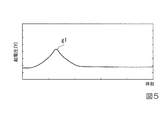
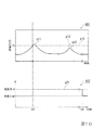
図5は、ガラス20を利用者が叩いた場合の圧電素子60が発生する起電圧の一例である。図5において、横軸は時間を表し、縦軸は起電圧のレベルを表している。図5における曲線g1は、利用者がガラス20を叩いたときに、圧電素子60が発生する起電圧を表している。
FIG. 5 is an example of an electromotive voltage generated by the
このように、利用者がガラス20や電子時計1の本体を叩くと、圧電素子60から起電圧が生じる。この起電圧は、図3および図4におけるゲイン切替部107、検出部105を介して、制御部102に供給される。これにより、制御部102は、検出部105からのタップ検出信号VSを取得して、所定の処理を実行できる。
Thus, when the user strikes the
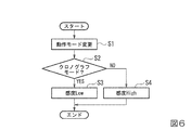
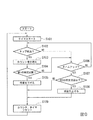
図6は、本発明の第1の実施形態に係る感度設定処理のフローチャートである。
(ステップS1)制御部102は、入力部103が検出した検出結果に基づいて、利用者により動作モードが変更されたことを検出する。制御部102は、ステップS1が終了後、処理をステップS2に進める。
(ステップS2)制御部102は、動作モードがクロノグラフモードに設定されたか否かを判別する。なお、クロノグラフモードは、ストップウォッチの機能を実現するものである。制御部102は、動作モードがクロノグラフモードに設定されたと判別した場合(ステップS2;YES)、ステップS3に進み、動作モードがクロノグラフモードに設定されていないと判別した場合(ステップS2;NO)、ステップS4に進む。
FIG. 6 is a flowchart of sensitivity setting processing according to the first embodiment of the present invention.
(Step S <b> 1) The
(Step S2) The
(ステップS3)制御部102は、検出感度を「Low」に設定する。すなわち、制御部102は、検出感度を「Low」とするための制御信号を、図4におけるゲイン切替部107に供給し、ゲイン切替部107は、この制御信号により、圧電素子60の検出感度が「Low」となるように、可変増幅器202のゲインを設定する。
(Step S <b> 3) The
(ステップS4)制御部102は、検出感度を「High」に設定する。すなわち、制御部102は、検出感度を「High」とするための制御信号を、図4におけるゲイン切替部107に供給し、ゲイン切替部107は、この制御信号により、圧電素子60の検出感度が「High」となるように、可変増幅器202のゲインを設定する。
ステップS3またはS4終了後、感度設定処理を終了する。
(Step S <b> 4) The
After step S3 or S4 ends, the sensitivity setting process ends.
以上のように、本実施形態の電子機器(電子時計1)は、自電子機器本体の一部に固定された圧電素子60と、圧電素子が外部から受けた衝撃に応じて発生した起電圧に対するゲインを切り替えることにより、圧電素子の検出感度を切り替えるゲイン切替部107と、歩行又は走行を表す情報を判定し、歩行又は走行を表す情報に基づいて、圧電素子の検出感度を切り替える制御部102と、を備える。
また、本実施形態の電子機器(電子時計1)において、歩行又は走行を表す情報は動作モードであり、制御部102は、設定された動作モードを判定し、設定された動作モードに基づいて、圧電素子60の検出感度を切り替える。
また、本実施形態の電子機器(電子時計1)において、動作モードは、ストップウォッチ計測に関連するモードであり、制御部102は、設定モードがストップウォッチ計測に関連するモードである場合には、圧電素子60の検出感度を下げるように制御する。
As described above, the electronic device (electronic timepiece 1) of the present embodiment has a
Further, in the electronic device (electronic timepiece 1) of the present embodiment, information representing walking or running is an operation mode, and the
In the electronic device (electronic timepiece 1) of the present embodiment, the operation mode is a mode related to stopwatch measurement, and the
この構成によって、本実施形態では、設定モードがクロノグラフモードのときには、圧電素子60の検出感度が「Low」となるように、ゲイン切替部107のゲインを設定している。これにより、ランニング中の利用者の腕振りによる誤検出を低減できる。
With this configuration, in this embodiment, when the setting mode is the chronograph mode, the gain of the
すなわち、設定モードがクロノグラフモードのときには、利用者はランニング中(歩行又は走行中)である可能性が高い。この場合、利用者の腕振りによる振動が電子時計1に加わり、検出部105からタップ検出信号VSが誤検出される可能性が高い。そこで、設定モードがクロノグラフモードのときには、圧電素子60の検出感度を「Low」に設定する。圧電素子60の検出感度を「Low」に設定すると、ゲイン切替部107の可変増幅器202のゲインは小さくなる。可変増幅器202のゲインが小さければ、利用者の腕振りによる振動で圧電素子60から起電圧が生じても、ゲイン切替部107の出力信号が閾値電圧Vthまで増幅されず、検出部105からタップ検出信号VSは出力されない。このため、ランニング中の利用者の腕振りによる誤検出を低減できる。
That is, when the setting mode is the chronograph mode, the user is likely to be running (walking or running). In this case, vibration due to the user's arm swing is applied to the electronic timepiece 1, and there is a high possibility that the tap detection signal VS is erroneously detected from the
設定モードがクロノグラフモード以外の他のモード、例えば時計モードのときには、ランニング中の利用者の腕振りのような、強い振動が電子時計1に加わる可能性は低い。そこで、他のモードのときには、圧電素子60の検出感度を「High」に設定する。圧電素子60の検出感度を「High」に設定すれば、可変増幅器202のゲインは大きくなる。したがって、タップ入力を行う際に、利用者は、ガラス20や電子時計1の本体を強く叩くことなく、所定の処理を実行できる。
When the setting mode is a mode other than the chronograph mode, for example, the timepiece mode, there is a low possibility that strong vibration such as a user's arm swing during running is applied to the electronic timepiece 1. Therefore, in other modes, the detection sensitivity of the
なお、上述の例では、ゲイン切替部107により設定できる検出感度は、「High」、「Mid」、「Low」の3段階の例を説明したが、これに限られない。設定感度は、3段階より多い検出感度を設定できるようにしてもよい。または、設定感度は、3段階より少なくてもよく、2段階でもよい。
In the above-described example, the detection sensitivity that can be set by the
[第2実施形態]
次に、第2実施形態について説明する。上述の第1実施形態では、設定モードがクロノグラフモードのときには、利用者がランニングを行っている可能性が高いことから、圧電素子60の検出感度を「Low」に設定することで、ランニング中の利用者の腕振りによるタップ検出信号VSの誤検出を防止している。
[Second Embodiment]
Next, a second embodiment will be described. In the first embodiment described above, when the setting mode is the chronograph mode, it is highly possible that the user is running. Therefore, by setting the detection sensitivity of the
これに対して、本実施形態では、所定時間内での圧電素子60からのタップ検出信号VSをカウントし、この所定時間内でのタップ検出信号VSのカウント値(検出回数、検出個数)から、利用者がランニングしている可能性が高いかどうかを判定している。そして、所定時間内でのタップ検出信号VSのカウント値から、利用者がランニングしている可能性が高いと判定された場合には、圧電素子60の検出感度を下げることにより、ランニング中の利用者の腕振りによるタップ検出信号VSの誤検出を防止している。なお、タップ検出信号VSの数とは、タップ検出信号VSの検出回数、またはタップ検出信号VSの個数である。
On the other hand, in the present embodiment, the tap detection signal VS from the
つまり、ランニング中の腕振り動作は、所定周期で行われる。したがって、所定時間内のタップ検出信号VSのカウント値が所定数に達したら、このタップ検出信号VSは、利用者のランニング中の腕振りによる信号であると考えられる。このことから、本実施形態では、例えば20秒間に第1の所定数(例えば5回または5個)のタップ検出信号VSが検出されたか否かを判定し、例えば20秒間に第1の所定数(例えば5回または5個)のタップ検出信号VSが検出された場合には、このタップ検出信号VSは、ランニング中の腕振りによる信号であるとして、圧電素子60の検出感度を下げるようにしている。これにより、ランニング中の腕振りによる影響を受けない最適な感度に、圧電素子60の検出感度を設定できる。他の構成については、第1の実施形態と同様である。
That is, the arm swinging motion during running is performed at a predetermined cycle. Therefore, when the count value of the tap detection signal VS within a predetermined time reaches a predetermined number, the tap detection signal VS is considered to be a signal generated by swinging the arm while the user is running. Therefore, in the present embodiment, for example, it is determined whether or not a first predetermined number (for example, 5 times or 5) of tap detection signals VS is detected in 20 seconds, and for example, the first predetermined number in 20 seconds. When (for example, five times or five) tap detection signals VS are detected, the tap detection signal VS is assumed to be a signal due to arm swing during running, and the detection sensitivity of the
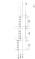
図7は、本実施形態に係る最適な感度を設定するときの処理の説明図である。図8は、本実施形態に係る感度を戻す処理の説明図である。図7および図8において、横軸は時間を示し、縦軸は圧電素子60の検出感度を示している。なお、初期状態では、圧電素子60の検出感度がHigh」に設定されている。
FIG. 7 is an explanatory diagram of processing when setting the optimum sensitivity according to the present embodiment. FIG. 8 is an explanatory diagram of processing for returning sensitivity according to the present embodiment. 7 and 8, the horizontal axis indicates time, and the vertical axis indicates the detection sensitivity of the
図7において、時刻t1のとき、1つ目のタップ検出信号VSが検出される。このため、制御部102は、時刻t1から時間T1(20秒間)のタイマー動作を開始し、検出部105からのタップ検出信号VSのカウントを開始する。図7では、利用者は、例えばランニングをしており、時間T1(20秒間)に、このランニングの腕振りによるタップ検出信号VSがカウントされている。ランニング中の利用者の腕振りによる場合、タップ検出信号VSは、所定時間内に、連続して多数現れるという特徴がある。
図7に示した例では、時刻t2のとき、20秒間に5回(または5個)のタップ検出信号VSが検出されたため、制御部102は、ランニングの腕振りによるタップ検出信号VSが検出されていると判定し、圧電素子60の検出感度を「Mid」に下げる。そして、時刻t3のとき、制御部102は、タイマーのカウントを終了し、さらにタップ検出信号VSのカウントをリセットする。また、制御部102は、時刻t2以降、圧電素子60の検出感度を「Mid」を継続する。
In FIG. 7, at time t1, the first tap detection signal VS is detected. For this reason, the
In the example shown in FIG. 7, since the tap detection signal VS is detected five times (or five) in 20 seconds at the time t2, the
次に、時刻t4のとき、再び1つ目のタップ検出信号VSが検出される。このため、制御部102は、時刻t4から時間T2(20秒間)のタイマー動作を開始し、検出部105からのタップ検出信号VSのカウントを開始する。そして、制御部102は、時間T2(20秒間)の期間、検出部105からのタップ検出信号VSをカウントする。
図7に示した例では、時間T2(20秒間)の期間のタップ検出信号VSのカウント値は、「4」であり、5回(または5個)に達しない。この場合、制御部102は、20秒間に5回(または5個)のタップ検出信号VSが検出されないので、圧電素子60の検出感度を「Mid」のままに設定する。
次に、時刻t5のとき、制御部102は、タイマーのカウントを終了し、さらにタップ検出信号VSのカウントをリセットする。また、制御部102は、時刻t5以降も、圧電素子60の検出感度を「Mid」を継続する。
Next, at time t4, the first tap detection signal VS is detected again. For this reason, the
In the example shown in FIG. 7, the count value of the tap detection signal VS in the period of time T2 (20 seconds) is “4”, and does not reach 5 times (or 5). In this case, since the tap detection signal VS is not detected five times (or five) in 20 seconds, the
Next, at time t5, the
次に、時刻t6のとき、再び1つ目のタップ検出信号VSが検出される。このため、制御部102は、時刻t6から時間T3(20秒間)のタイマー動作を開始し、検出部105からのタップ検出信号VSのカウントを開始する。そして、制御部102は、時間T3(20秒間)の期間、検出部105からのタップ検出信号VSをカウントする。
図7に示した例では、時間T3(20秒間)の期間のタップ検出信号VSのカウント値が5回(または5個)に達した時刻t7のとき、制御部102は、圧電素子60の検出感度を「Low」に設定する。
次に、時刻t8のとき、制御部102は、タイマーのカウントを終了し、さらにタップ検出信号VSのカウントをリセットする。また、制御部102は、時刻t8以降も、圧電素子60の検出感度を「Low」を継続する。時刻t7以降では、圧電素子60の検出感度を「Low」に下げたことから、ランニングの腕振りによるタップ検出信号VSは検出されていない。
Next, at time t6, the first tap detection signal VS is detected again. For this reason, the
In the example illustrated in FIG. 7, the
Next, at time t8, the
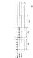
次に、圧電素子60の検出感度を戻すときの処理を説明する。図7の説明では、所定時間内に第1の所定数(例えば20秒間に5回または5個)のタップ検出信号VSが検出された場合には、圧電素子60の検出感度を下げるようにしている。ところが、検出感度を下げる処理だけでは、圧電素子60の検出感度が下がり過ぎてしまうことがある。そこで、この実施形態では、所定時間内(例えば20秒間)のタップ検出信号VSのカウント値が第2の所定数(例えば0回または0個)以下である場合には、圧電素子60の検出感度を上げるような処理を行っている。
Next, a process for returning the detection sensitivity of the
つまり、図8において、時間T11(20秒間)の期間では、制御部102は、圧電素子60の検出感度を「High」に設定し、検出部105からのタップ検出信号VSをカウントする。図8では、時間T11(20秒間)の期間でのタップ検出信号VSのカウント値が5回(または5個)に達すると、制御部102は、圧電素子60の検出感度を「Mid」に設定する。そして、時間T12(20秒間)の期間では、制御部102は、圧電素子60の検出感度を「Mid」に設定し、検出部105からのタップ検出信号VSをカウントする。
That is, in FIG. 8, in the period of time T <b> 11 (20 seconds), the
時刻t11およびt14のとき、1つ目のタップ検出信号VSが検出される。このため、制御部102は、時刻t11から時間T11(20秒間)のタイマー動作を開始し、時刻t14から時間T12(20秒間)のタイマー動作を開始する。そして、制御部102は、時刻t11およびt14のとき、検出部105からのタップ検出信号VSのカウントを開始する。また、制御部102は、時刻t15から時間T13(20秒間)のタイマー動作を開始する。
At times t11 and t14, the first tap detection signal VS is detected. For this reason, the
図8の示した例では、時間T11(20秒間)の期間でのタップ検出信号VSのカウント値が5回(または5個)に達した時刻t12のとき、制御部102は、圧電素子60の検出感度を「Mid」に設定する。また、時間T12(20秒間)の期間でのタップ検出信号VSのカウント値が5回(または5個)に達した時刻t15のとき、制御部102は、圧電素子60の検出感度を「Low」に設定する。
そして、時間T13(20秒間)の期間、制御部102は、検出部105からのタップ検出信号VSをカウントする。
In the example shown in FIG. 8, at time t <b> 12 when the count value of the tap detection signal VS in the period of time T <b> 11 (20 seconds) reaches 5 times (or 5), the
Then, during the period of time T13 (20 seconds), the
図8に示した例では、時間T13(20秒間)の期間でのタップ検出信号VSのカウント値は、「0」となる。この場合、制御部102は、20秒間、タップ検出信号VSが検出されないので、時刻t17のとき、圧電素子60の検出感度を「Low」から「Mid」に上げるように設定する。
そして、制御部102は、時刻t17以降、圧電素子60の検出感度を「Mid」に設定し、検出部105からのタップ検出信号VSをカウントする。なお、時刻t17以降、20秒間の期間でのタップ検出信号VSのカウント値が0回以下の場合、制御部102は、圧電素子60の検出感度を「Mid」から「High」に戻すように設定する。
In the example shown in FIG. 8, the count value of the tap detection signal VS in the period of time T13 (20 seconds) is “0”. In this case, since the tap detection signal VS is not detected for 20 seconds, the
Then, after time t17, the
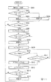
図9は、本実施形態に係る処理のフローチャートである。なお、図9では、制御部102がタップ検出信号VSの検出回数をカウント値としてカウントし、カウント値に基づいて処理を行う例を説明する。
(ステップS101)制御部102は、タイマー動作を開始する。
(ステップS102)制御部102は、検出部105からのタップ検出信号VSが検出されたか否かを判別する。制御部102は、検出部105からのタップ検出信号VSが検出されたと判別した場合(ステップS102;YES)、ステップS103に進み、検出部105からのタップ検出信号VSが検出されていないと判別した場合(ステップS102;NO)、ステップS106に進む。
FIG. 9 is a flowchart of processing according to the present embodiment. FIG. 9 illustrates an example in which the
(Step S101) The
(Step S <b> 102) The
(ステップS103)制御部102は、カウント値を1つ増加する。
(ステップS104)制御部102は、カウント値が第1の所定回数(第1の所定数)(例えば5回)に達したか否かを判別する。制御部102は、カウント値が第1の所定回数に達したと判別した場合(ステップS104:YES)、ステップS105に進み、カウント値が第1の所定回数に達していないと判別した場合(ステップS104:NO)、ステップS106に進む。
(Step S103) The
(Step S104) The
(ステップS105)制御部102は、ランニング中であると判別し、感度を1段下げる。制御部102は、処理をステップS109に進める。
(ステップS106)制御部102は、タイムアップ(例えば2秒)したか否かを判別する。制御部102は、タイムアップしたと判別した場合(ステップS106;YES)、ステップS107に進み、タイムアップしていないと判別した場合(ステップS106;NO)、ステップS102に戻る。制御部102は、ステップS102からステップS106の処理を繰り返すことにより、所定時間(例えば20秒)内で、タップ検出信号VSをカウントする。
(Step S105) The
(Step S106) The
(ステップS107)所定時間(例えば20秒)経過しても、タップ検出信号VSをカウント値が第1の所定回数に達していない場合、制御部102は、タップ検出信号VSのカウント値が第2の所定回数(第2の所定数)(例えば0回)以下であるか否かを判別する。制御部102は、タップ検出信号VSのカウント値が第2の所定回数以下であると判別した場合(ステップS107;YES)、ステップS108に進み、タップ検出信号VSのカウント値が第2の所定回数以下ではないと判別した場合(ステップS107;NO)、ステップS109に進む。
(Step S107) If the count value of the tap detection signal VS has not reached the first predetermined number of times even after a predetermined time (for example, 20 seconds) has elapsed, the
(ステップS108)制御部102は、感度を1段上げる。制御部102は、ステップS108終了後、処理をステップS109に進める。
(ステップS109)制御部102は、検出値をカウントするカウンタと、タイマーとをリセットし、ステップS101に処理を戻す。
(Step S108) The
(Step S109) The
なお、本実施形態では、ステップS107において、第1の所定回数(第1の所定数)として5回の例を説明したが、これに限られない。また、ステップS110において、第2の所定回数(第2の所定数)として0回の例を説明したが、これに限られない。圧電素子60の特性、電子時計1のケース10の材質や厚さに応じて、例えば実験によって回数を決定するようにしてもよい。例えば、第2の所定回数は1回であってもよい。この場合、ステップS107において、制御部102は、タップ検出信号VSのカウント値が1回以下であるか否かを判別する。
In the present embodiment, the example of five times as the first predetermined number of times (first predetermined number) has been described in step S107, but the present invention is not limited to this. Moreover, although the example of 0 times was demonstrated as 2nd predetermined number of times (2nd predetermined number) in step S110, it is not restricted to this. Depending on the characteristics of the
なお、制御部102がカウントする値は、タップ検出信号VSの数であってもよい。この場合、ステップS104において、制御部102は、タップ検出信号VSの数であるカウント値が第1の所定数(例えば5個)に達したか否かを判別するようにしてもよい。同様に、ステップS107において、制御部102は、タップ検出信号VSの数であるカウント値が第2の所定数(例えば0個)以下であるか否かを判別するようにしてもよい。
Note that the value counted by the
以上説明したように、本実施形態の電子機器(電子時計1)において、歩行又は走行を表す情報は所定時間内での圧電素子60の検出信号の数(カウント値)であり、制御部102は、所定時間内での圧電素子の検出信号をカウントし、所定時間内での圧電素子の検出信号の数に基づいて、前記圧電素子の検出感度を切り替える。
また、本実施形態の電子機器(電子時計1)において、制御部102は、所定時間内での圧電素子60の検出信号の数(カウント値)が第1の所定数に達した場合には、圧電素子の検出感度を下げるように制御する。
また、本実施形態の電子機器(電子時計1)において、制御部102は、所定時間内での圧電素子60の検出信号の数(カウント値)が第2の所定数以下である場合には、圧電素子の検出感度を上げるように制御する。
As described above, in the electronic device (electronic timepiece 1) of the present embodiment, the information indicating walking or running is the number (count value) of detection signals of the
Further, in the electronic device (electronic timepiece 1) of the present embodiment, the
Further, in the electronic device (electronic timepiece 1) of the present embodiment, the
この構成によって、本実施形態では、所定時間内のタップ検出信号VSのカウント値が第1の所定数(例えば20秒間に5回または5個)に達した場合には、このタップ検出信号VSは、ランニング中(歩行又は走行中)の腕振りによる誤検出であるとして、圧電素子60の検出感度を下げるようにしている。また、本実施形態では、所定時間内のタップ検出信号VSのカウント値が第2の所定数(例えば20秒間に0回または0個)以下である場合には、圧電素子60の検出感度を上げるようにしている。これにより、ランニング中の腕振りによる影響を受けない最適な感度に、圧電素子60の検出感度を設定することができる。
With this configuration, in this embodiment, when the count value of the tap detection signal VS within a predetermined time reaches a first predetermined number (for example, 5 times or 5 times in 20 seconds), the tap detection signal VS is The detection sensitivity of the
[第3実施形態]
次に、本実施形態について説明する。上述のように、本実施形態では、利用者がガラス20や電子時計1の本体を叩くと、この振動が圧電素子60で検出され、所定の処理が実行される。また、このように、利用者がガラス20や電子時計1の本体を叩くことにより各種の動作を行わせる場合、利用者が電子機器を叩く回数により、異なる動作に設定できる。例えば、電子機器を1回叩いた場合(シングルタップ)と、2回連続して叩いた場合(ダブルタップ)とで、異なる動作に設定されるようにすることが考えられる。
[Third Embodiment]
Next, this embodiment will be described. As described above, in the present embodiment, when the user hits the
図10は、利用者がガラス20をダブルタップしたときの、圧電素子60が発生する起電圧とゲイン切替部107のゲインの状態を表している。図10において、横軸は時間を表し、縦軸は起電圧のレベルを表している。図10の符号401で示した領域の画像は、圧電素子60が発生する起電圧を表す画像である。曲線g11は1回目のタップの起電圧を示し、曲線g12は2回目のタップの起電圧を示し、曲線g13は、ゲインを上げたとき検出部105に入力される信号を示している。また、破線g14は、タップ検出信号VSを検出する閾値を示している。
また、図10の符号402で示した画像は、ゲイン切替部107のゲインの状態の画像である。曲線g21は、圧電素子60の検出感度を示している。図10に示すように、利用者がダブルタップを行う場合、通常、利用者は、1回目のタップでは強く叩き、2回目のタップでは弱く叩く傾向にある。このため、利用者がダブルタップを行っても、ダブルタップと判別されずに、シングルタップと判別されてしまう場合がある。
FIG. 10 shows the state of the electromotive voltage generated by the
Also, an image indicated by
そこで、本実施形態では、クロノグラフモードで圧電素子60の検出感度が「Low」に設定された場合、時刻t21のとき1回目のタップに相当するタップ検出信号VSが検出されたら、圧電素子60の検出感度を曲線g21のように上げるようにしている。そして、所定時間内(例えば2秒以内)に、2回目のタップに相当するタップ検出信号VSが検出されたら、ダブルタップとして入力を行い、2回目のタップに相当する検出信号が検出されなければ、シングルタップとして入力を行うようにしている。また、図10の曲線g21に示すように、検出信号を検出して所定の時間経過後の時刻t22のとき、圧電素子60の検出感度を「Mid」から「Low」に変更するようにしてもよい。
これにより、クロノグラフモードで圧電素子の検出感度を下げた場合にも、ダブルタップを確実に識別することができる。
Therefore, in the present embodiment, when the detection sensitivity of the
Thereby, even when the detection sensitivity of the piezoelectric element is lowered in the chronograph mode, the double tap can be reliably identified.
図11は、本実施形態に係る処理のフローチャートである。
(ステップS501)制御部102は、入力部103が検出した検出結果に基づいて、利用者により動作モードが変更されたことを検出し、処理をステップS501に進める。
(ステップS502)制御部102は、動作モードがクロノグラフモードであるか否かを判別する。制御部102は、動作モードがクロノグラフモードであると判別した場合(ステップS502;YES)、ステップS503に進み、動作モードがクロノグラフモードではないと判別した場合(ステップS502;NO)、ステップS504に進める。
(ステップ503)制御部102は、検出感度を「Low」に設定する。
(ステップS504)制御部102は、検出感度を「High」に設定する。
FIG. 11 is a flowchart of processing according to the present embodiment.
(Step S501) Based on the detection result detected by the
(Step S502) The
(Step 503) The
(Step S504) The
(ステップS505)制御部102は、タップ検出信号VSが検出されたか否かを判別する。制御部102は、タップ検出信号VSが検出されたと判別した場合(ステップS505;YES)、ステップS506に進み、タップ検出信号VSが検出されていないと判別した場合(ステップS505;NO)、ステップS505を繰り返す。
(ステップS506)制御部102は、ステップS505においてタップ検出信号VSが検出されため、シングルタップが入力されたと判別する。
(Step S505) The
(Step S506) Since the tap detection signal VS is detected in step S505, the
(ステップS507)制御部102は、動作モードがクロノグラフモードであるか否かを判別する。制御部102は、動作モードがクロノグラフモードであると判別した場合(ステップS507;YES)、ステップS508に進み、動作モードがクロノグラフモードではないと判別した場合(ステップS507;NO)、ステップS509に進む。
(Step S507) The
(ステップS508)制御部102は、圧電素子60の検出感度を現在の設定値より1段階上の「Mid」に上げる。なお、動作モードがクロノグラフモード以外の場合(ステップS507;NO)、ステップS504で感度は既に「High」に設定されているので、感度の変更は行わない。
(ステップS509)制御部102は、タイマーをスタートさせ、タップ検出信号VSの検出を開始する。
(Step S <b> 508) The
(Step S509) The
(ステップS510)制御部102は、タップ検出信号VSが検出されたか否かを判別する。制御部102は、タップ検出信号VSが検出されたと判別した場合(ステップS510;YES)、ステップS512に進み、タップ検出信号VSが検出されていないと判別した場合(ステップS510;NO)、ステップS511に進む。
(Step S510) The
(ステップS511)制御部102は、タイムアップ(例えば2秒)したか否かを判別する。制御部102は、タイムアップしたと判別した場合(ステップS511;YES)、ステップS513に進み、タイムアップしていないと判別した場合(ステップS511;NO)、ステップS510に戻る。
(ステップS512)制御部102は、タップ検出信号VSが、ステップS505において検出され、さらにステップS510で検出されたため、ダブルタップが入力されたと判別する。
(Step S511) The
(Step S512) Since the tap detection signal VS is detected in step S505 and further detected in step S510, the
(ステップS513)シングルタップ又はダブルタップの入力が検出されたら、制御部102は、タイマーをリセットする。
(ステップS514)制御部102は、動作モードがクロノグラフモードであるか否かを判別する。制御部102は、動作モードがクロノグラフモードであると判別した場合(ステップS514;YES)、ステップS515に進み、動作モードがクロノグラフモードではないと判別した場合(ステップS514;NO)、ステップS505に戻る。
(ステップS515)制御部102は、圧電素子60の検出感度を「Low」に戻す。
制御部102は、ステップS515終了後、処理をステップS505に戻す。
(Step S513) If the input of a single tap or a double tap is detected, the
(Step S514) The
(Step S515) The
After the end of step S515,
なお、上述の例では、クロノグラフモードでは、圧電素子60の検出感度を「Low」に設定した後、1回目のタップ検出後に検出感度を「Mid」に上げている。このように、図11に示した例では、クロノグラフモードの場合、1回目のタップ検出後に検出感度の設定を、他のモードでの検出感度の設定値である「High」よりも低い「Mid」に設定することで、利用者の腕の動きによる誤検出を考慮しつつ、シングルタップとダブルタップとを確実に識別できるようにしている。
In the above example, in the chronograph mode, after the detection sensitivity of the
また、上述した例では、クロノグラフモードの場合に、ステップS508において検出感度を「Mid」に上げる例を説明したが、これに限られない。
図12は、本実施形態に係る電子時計1Aの他の構成を示したブロック図である。図12に示すように、電子時計1Aは、発振部101、制御部102A、入力部103、表示制御部104、圧電素子60、表示部90、検出部105、ゲイン切替部107、記憶部106、及び加速度センサ108を備える。なお、図3に示した電子時計1と同じ機能を有する機能部には、同じ符号を用いる。図12に示す電子時計1Aは、図3に示した電子時計1に加えて加速度センサ108を備えている。
In the example described above, in the chronograph mode, the example in which the detection sensitivity is increased to “Mid” in step S508 has been described. However, the present invention is not limited to this.
FIG. 12 is a block diagram showing another configuration of the electronic timepiece 1A according to the present embodiment. As shown in FIG. 12, the electronic timepiece 1A includes an
加速度センサ108は、相互に直交する直交座標軸のX成分、Y成分、Z成分の加速度を検出値として検出するセンサである。加速度センサ108は、検出した各成分の加速度に対応する大きさの検出値を制御部102Aに出力する。
The
制御部102Aは、加速度センサ108から入力された検出値に基づいて、利用者が走行中、歩行中、または停止中のうち、いずれかの状態であるかを判別し、判別した結果に基づいて動作モードを決定するようにしてもよい。例えば、制御部102Aは、利用者が走行中の状態を第1の動作モード、利用者が歩行中の状態を第2の動作モードと決定するようにしてもよい。または、制御部102Aは、利用者が走行中または歩行中の状態を第1の動作モード、利用者が停止中の状態を第2の動作モードと決定するようにしてもよい。そして、制御部102Aは、決定した動作モードに応じて、第1の動作モードのときと第2の動作モードのときとで圧電素子60の検出感度を切り替えるようにしてもよい。
Based on the detection value input from
勿論、圧電素子60の検出感度を「Low」に設定した後、1回目のタップ検出後に検出感度を「High」に上げ、シングルタップ又はダブルタップ入力の検出後に、検出感度を「Low」に戻すようにしても良い。また、この例では、クロノグラフモードの場合にのみ、1回目のタップ検出後に検出感度を上げているが、クロノグラフモード以外のときにも、1回目のタップ検出後に検出感度を上げるようにしてもよい。
Of course, after the detection sensitivity of the
なお、本実施形態では、電子時計1の動作モードに応じて、検出感度を変更する例を説明したが、動作モードの検出は行わなくてもよく、また動作モードに応じた感度の変更も行わなくてもよい。すなわち、一回目のタップを検出したとき、検出感度を設定されている感度から上げるようにしてもよい。この場合、例えば、図11のステップS505から処理を開始し、ステップS505終了後にステップS507に進み、ステップS507で感度を上げるようにしてもよい。 In the present embodiment, the example in which the detection sensitivity is changed according to the operation mode of the electronic timepiece 1 has been described. However, the operation mode may not be detected, and the sensitivity may be changed according to the operation mode. It does not have to be. That is, when the first tap is detected, the detection sensitivity may be increased from the set sensitivity. In this case, for example, the process may be started from step S505 in FIG. 11, and after step S505 ends, the process proceeds to step S507, and the sensitivity may be increased in step S507.
以上説明したように、本実施形態では、1番目のタップ検出信号VSが検出されたら、検出感度を上げるようにしている。このため、圧電素子の検出感度を下げた場合にも、シングルタップとダブルタップとを確実に識別できる。 As described above, in the present embodiment, when the first tap detection signal VS is detected, the detection sensitivity is increased. For this reason, even when the detection sensitivity of the piezoelectric element is lowered, the single tap and the double tap can be reliably identified.
なお、上述の例では、ダブルタップを確実に識別する例について説明したが、本実施形態は、更に、電子機器を3回、或いは4回等、複数回叩いた場合にも、同様に適用できる。 In the above-described example, the example in which the double tap is reliably identified has been described. However, the present embodiment can be similarly applied to a case where the electronic device is further tapped three times or four times. .
また、上述の例では、ガラス20や電子時計1の本体を叩いたことを圧電素子60で検出してシングルタップ及びダブルタップを検出しているが、スマートフォンと呼ばれる携帯端末やタブレット端末のように、タッチパネルの接触を検出して各種の動作を行う電子機器においても、利用者が1回目のタップでは強く接触し、2回目のタップでは弱く接触する傾向は同様である。したがって、タッチパネルの接触を検出して各種の動作を行う電子機器においても、1番目の検出信号が検出されたら、検出感度を上げるようにすることで、シングルタップとダブルタップとを識別するようにしても良い。
In the above example, the
なお、第1〜第3実施形態においては、電子機器の一例として電子時計1及び1Aに適用した例を説明したが、これに限られない。圧電素子60、制御部102(または102A)、ゲイン切替部107は、例えば、スマートフォン、タブレット端末、車載用のナビゲーションシステム、TV(テレビ)などの機器に適用することも可能である。
In the first to third embodiments, the example applied to the electronic timepieces 1 and 1A as an example of the electronic device has been described. However, the present invention is not limited to this. The
なお、本発明における制御部102(または102A)およびゲイン切替部107の機能を実現するためのプログラムをコンピュータ読み取り可能な記録媒体に記録して、この記録媒体に記録されたプログラムをコンピュータシステムに読み込ませ、実行することにより制御部102およびゲイン切替部107の動作および制御を行ってもよい。なお、ここでいう「コンピュータシステム」とは、OSや周辺機器等のハードウェアを含むものとする。また、「コンピュータシステム」は、ホームページ提供環境(あるいは表示環境)を備えたWWWシステムも含むものとする。また、「コンピュータ読み取り可能な記録媒体」とは、フレキシブルディスク、光磁気ディスク、ROM、CD−ROM等の可搬媒体、コンピュータシステムに内蔵されるハードディスク等の記憶装置のことをいう。さらに「コンピュータ読み取り可能な記録媒体」とは、インターネット等のネットワークや電話回線等の通信回線を介してプログラムが送信された場合のサーバやクライアントとなるコンピュータシステム内部の揮発性メモリ(RAM)のように、一定時間プログラムを保持しているものも含むものとする。
A program for realizing the functions of the control unit 102 (or 102A) and the
また、上記プログラムは、このプログラムを記憶装置等に格納したコンピュータシステムから、伝送媒体を介して、あるいは、伝送媒体中の伝送波により他のコンピュータシステムに伝送されてもよい。ここで、プログラムを伝送する「伝送媒体」は、インターネット等のネットワーク(通信網)や電話回線等の通信回線(通信線)のように情報を伝送する機能を有する媒体のことをいう。また、上記プログラムは、前述した機能の一部を実現するためのものであってもよい。さらに、前述した機能をコンピュータシステムにすでに記録されているプログラムとの組み合わせで実現できるもの、いわゆる差分ファイル(差分プログラム)であってもよい。 The program may be transmitted from a computer system storing the program in a storage device or the like to another computer system via a transmission medium or by a transmission wave in the transmission medium. Here, the “transmission medium” for transmitting the program refers to a medium having a function of transmitting information, such as a network (communication network) such as the Internet or a communication line (communication line) such as a telephone line. The program may be for realizing a part of the functions described above. Furthermore, what can implement | achieve the function mentioned above in combination with the program already recorded on the computer system, what is called a difference file (difference program) may be sufficient.
1、1A…電子時計、10…ケース、20…ガラス、30…基盤、40…電池、50…電極、60…圧電素子、70…裏蓋、80…ベルト、90…表示部、101…発振部、102、102A…制御部、103…入力部、104…表示制御部、105…検出部、106…記憶部、107…ゲイン切替部、108…加速度センサ DESCRIPTION OF SYMBOLS 1, 1A ... Electronic timepiece, 10 ... Case, 20 ... Glass, 30 ... Base, 40 ... Battery, 50 ... Electrode, 60 ... Piezoelectric element, 70 ... Back cover, 80 ... Belt, 90 ... Display part, 101 ... Oscillation part , 102, 102A ... control unit, 103 ... input unit, 104 ... display control unit, 105 ... detection unit, 106 ... storage unit, 107 ... gain switching unit, 108 ... acceleration sensor
Claims (9)
前記圧電素子が外部から受けた衝撃に応じて発生した起電圧に対するゲインを切り替えることにより、前記圧電素子の検出感度を切り替えるゲイン切替部と、
歩行又は走行を表す情報を判定し、前記歩行又は走行を表す情報に基づいて、前記圧電素子の検出感度を切り替える制御部と、
を備えることを特徴とする電子機器。 A piezoelectric element fixed to a part of the electronic device main body,
A gain switching unit that switches detection sensitivity of the piezoelectric element by switching a gain for an electromotive voltage generated in response to an impact received by the piezoelectric element from the outside;
A control unit that determines information representing walking or running and switches detection sensitivity of the piezoelectric element based on the information representing walking or running;
An electronic device comprising:
前記制御部は、設定された動作モードを判定し、前記設定された動作モードに基づいて、前記圧電素子の検出感度を切り替える
ことを特徴とする請求項1に記載の電子機器。 The information representing the walking or running is an operation mode,
The electronic device according to claim 1, wherein the control unit determines a set operation mode, and switches the detection sensitivity of the piezoelectric element based on the set operation mode.
前記制御部は、前記動作モードが前記ストップウォッチ計測に関連するモードである場合には、前記圧電素子の検出感度を下げるように制御する
ことを特徴とする請求項2に記載の電子機器。 The operation mode is a mode related to stopwatch measurement,
The electronic device according to claim 2, wherein the control unit controls the detection sensitivity of the piezoelectric element to be lowered when the operation mode is a mode related to the stopwatch measurement.
前記動作モードは、前記加速度センサによって検出された結果に基づくモードであり、
前記制御部は、前記加速度センサによって検出された結果に基づくモードに応じて、前記圧電素子の検出感度を切り替える
ことを特徴とする請求項2に記載の電子機器。 It has an acceleration sensor that detects the acceleration applied to its own electronic device,
The operation mode is a mode based on a result detected by the acceleration sensor,
The electronic device according to claim 2, wherein the control unit switches detection sensitivity of the piezoelectric element according to a mode based on a result detected by the acceleration sensor.
前記制御部は、前記所定時間内での圧電素子の検出信号をカウントし、前記所定時間内での圧電素子の検出信号の数に基づいて、前記圧電素子の検出感度を切り替える
ことを特徴とする請求項1に記載の電子機器。 The information representing the walking or running is the number of detection signals of the piezoelectric element within a predetermined time,
The control unit counts the detection signal of the piezoelectric element within the predetermined time, and switches the detection sensitivity of the piezoelectric element based on the number of detection signals of the piezoelectric element within the predetermined time. The electronic device according to claim 1.
ことを特徴とする請求項5に記載の電子機器。 The control unit controls to lower the detection sensitivity of the piezoelectric element when the number of detection signals of the piezoelectric element within the predetermined time reaches a first predetermined number. 5. The electronic device according to 5.
ことを特徴とする請求項5または請求項6に記載の電子機器。 The said control part is controlled to raise the detection sensitivity of the said piezoelectric element, when the number of the detection signals of the piezoelectric element in the said predetermined time is below a 2nd predetermined number. The electronic device according to claim 5 or 6.
歩行又は走行を表す情報を判定する判定手順と、
前記歩行又は走行を表す情報に基づいて、前記圧電素子の検出感度を切り替える制御手順と、
を含む電子機器の制御方法。 A method for controlling an electronic device in which a piezoelectric element is fixed to a part of the body of the electronic device,
A determination procedure for determining information representing walking or running;
Based on information representing the walking or running, a control procedure for switching the detection sensitivity of the piezoelectric element,
A method for controlling an electronic device.
歩行又は走行を表す情報を判定するステップと、
前記歩行又は走行を表す情報に基づいて、前記圧電素子の検出感度を切り替えるステップと、
を含むコンピュータにより実行可能な電子機器の制御プログラム。 A control program for an electronic device in which a piezoelectric element is fixed to a part of the electronic device main body,
Determining information representing walking or running;
Based on the information representing the walking or running, switching the detection sensitivity of the piezoelectric element;
An electronic device control program executable by a computer including:
Priority Applications (1)
| Application Number | Priority Date | Filing Date | Title |
|---|---|---|---|
| JP2013258393A JP2015114283A (en) | 2013-12-13 | 2013-12-13 | Electronic apparatus, method of controlling electronic apparatus, and control program of electronic apparatus |
Applications Claiming Priority (1)
| Application Number | Priority Date | Filing Date | Title |
|---|---|---|---|
| JP2013258393A JP2015114283A (en) | 2013-12-13 | 2013-12-13 | Electronic apparatus, method of controlling electronic apparatus, and control program of electronic apparatus |
Publications (1)
| Publication Number | Publication Date |
|---|---|
| JP2015114283A true JP2015114283A (en) | 2015-06-22 |
Family
ID=53528193
Family Applications (1)
| Application Number | Title | Priority Date | Filing Date |
|---|---|---|---|
| JP2013258393A Pending JP2015114283A (en) | 2013-12-13 | 2013-12-13 | Electronic apparatus, method of controlling electronic apparatus, and control program of electronic apparatus |
Country Status (1)
| Country | Link |
|---|---|
| JP (1) | JP2015114283A (en) |
Cited By (2)
| Publication number | Priority date | Publication date | Assignee | Title |
|---|---|---|---|---|
| WO2020110512A1 (en) * | 2018-11-29 | 2020-06-04 | シチズン時計株式会社 | Mobile device |
| JP2022505922A (en) * | 2019-06-17 | 2022-01-14 | ケーティー・アンド・ジー・コーポレーション | Aerosol generator and its operation method |
-
2013
- 2013-12-13 JP JP2013258393A patent/JP2015114283A/en active Pending
Cited By (8)
| Publication number | Priority date | Publication date | Assignee | Title |
|---|---|---|---|---|
| WO2020110512A1 (en) * | 2018-11-29 | 2020-06-04 | シチズン時計株式会社 | Mobile device |
| JPWO2020110512A1 (en) * | 2018-11-29 | 2021-10-14 | シチズン時計株式会社 | Mobile device |
| JP7354144B2 (en) | 2018-11-29 | 2023-10-02 | シチズン時計株式会社 | mobile device |
| JP2022505922A (en) * | 2019-06-17 | 2022-01-14 | ケーティー・アンド・ジー・コーポレーション | Aerosol generator and its operation method |
| JP7195420B2 (en) | 2019-06-17 | 2022-12-23 | ケーティー アンド ジー コーポレイション | Aerosol generator and method of operation |
| JP2023027260A (en) * | 2019-06-17 | 2023-03-01 | ケーティー アンド ジー コーポレイション | Aerosol generating device and operation method thereof |
| US12022884B2 (en) | 2019-06-17 | 2024-07-02 | Kt&G Corporation | Aerosol generating device and operation method thereof |
| JP7661295B2 (en) | 2019-06-17 | 2025-04-14 | ケーティー アンド ジー コーポレイション | Aerosol generating device and method of operation thereof |
Similar Documents
| Publication | Publication Date | Title |
|---|---|---|
| US9700260B2 (en) | Portable device and heartbeat reaching time measurement control method | |
| US9213434B2 (en) | Piezoelectric actuator and method | |
| US8260344B2 (en) | Electronic device and control program thereof | |
| CN110784601B (en) | motion sensor | |
| US20150371524A1 (en) | Methods and systems for alarm management in an electronic device | |
| KR20100106581A (en) | Touch sensor device, control method, touch panel device and program | |
| US9590697B2 (en) | Device environment determination | |
| WO2015015047A1 (en) | Distance estimation | |
| US20190391723A1 (en) | Touch recognition method, touch device | |
| JP2015114283A (en) | Electronic apparatus, method of controlling electronic apparatus, and control program of electronic apparatus | |
| US20120203503A1 (en) | Electronic device, pedometer, and program | |
| CN107003758B (en) | Ghost point processing method and user equipment | |
| JP2017068327A (en) | Electronic device and method of operating electronic device | |
| JP2016091052A (en) | Electronics | |
| JP5561028B2 (en) | Step counting device | |
| US11112268B2 (en) | Electronic device for performing step counting with false-positive rejection | |
| US20140243693A1 (en) | Electronic device, heart-rate receiving method and program | |
| JP2019125858A (en) | Electronic device, control device, and control program | |
| US20140290385A1 (en) | Electronic apparatus and shock detection method | |
| CN112558777A (en) | Screen on-off control method and device of wearable equipment and equipment | |
| JP6017326B2 (en) | Electronic device and control method of electronic device | |
| JP5022829B2 (en) | Remote control signal receiving circuit | |
| JP6643952B2 (en) | Electronic device, power control method for electronic device, and power control program | |
| US20120203496A1 (en) | Acceleration detecting device, electronic apparatus, pedometer, and program | |
| CN116295588A (en) | Wearing state detection method, device, equipment and storage medium |