JP2015114274A - Gas concentration measuring apparatus and replacement notification method - Google Patents
Gas concentration measuring apparatus and replacement notification method Download PDFInfo
- Publication number
- JP2015114274A JP2015114274A JP2013258283A JP2013258283A JP2015114274A JP 2015114274 A JP2015114274 A JP 2015114274A JP 2013258283 A JP2013258283 A JP 2013258283A JP 2013258283 A JP2013258283 A JP 2013258283A JP 2015114274 A JP2015114274 A JP 2015114274A
- Authority
- JP
- Japan
- Prior art keywords
- gas
- concentration
- sensor
- alcohol
- gas sensor
- Prior art date
- Legal status (The legal status is an assumption and is not a legal conclusion. Google has not performed a legal analysis and makes no representation as to the accuracy of the status listed.)
- Granted
Links
Images


Classifications
-
- G—PHYSICS
- G01—MEASURING; TESTING
- G01N—INVESTIGATING OR ANALYSING MATERIALS BY DETERMINING THEIR CHEMICAL OR PHYSICAL PROPERTIES
- G01N33/00—Investigating or analysing materials by specific methods not covered by groups G01N1/00 - G01N31/00
- G01N33/48—Biological material, e.g. blood, urine; Haemocytometers
- G01N33/483—Physical analysis of biological material
- G01N33/497—Physical analysis of biological material of gaseous biological material, e.g. breath
- G01N33/4972—Determining alcohol content
-
- A—HUMAN NECESSITIES
- A61—MEDICAL OR VETERINARY SCIENCE; HYGIENE
- A61B—DIAGNOSIS; SURGERY; IDENTIFICATION
- A61B5/00—Measuring for diagnostic purposes; Identification of persons
- A61B5/08—Measuring devices for evaluating the respiratory organs
- A61B5/082—Evaluation by breath analysis, e.g. determination of the chemical composition of exhaled breath
-
- G—PHYSICS
- G01—MEASURING; TESTING
- G01N—INVESTIGATING OR ANALYSING MATERIALS BY DETERMINING THEIR CHEMICAL OR PHYSICAL PROPERTIES
- G01N33/00—Investigating or analysing materials by specific methods not covered by groups G01N1/00 - G01N31/00
- G01N33/48—Biological material, e.g. blood, urine; Haemocytometers
- G01N33/483—Physical analysis of biological material
- G01N33/497—Physical analysis of biological material of gaseous biological material, e.g. breath
- G01N33/4975—Physical analysis of biological material of gaseous biological material, e.g. breath other than oxygen, carbon dioxide or alcohol, e.g. organic vapours
-
- A—HUMAN NECESSITIES
- A61—MEDICAL OR VETERINARY SCIENCE; HYGIENE
- A61B—DIAGNOSIS; SURGERY; IDENTIFICATION
- A61B2560/00—Constructional details of operational features of apparatus; Accessories for medical measuring apparatus
- A61B2560/02—Operational features
- A61B2560/0266—Operational features for monitoring or limiting apparatus function
- A61B2560/028—Arrangements to prevent overuse, e.g. by counting the number of uses
-
- B—PERFORMING OPERATIONS; TRANSPORTING
- B60—VEHICLES IN GENERAL
- B60K—ARRANGEMENT OR MOUNTING OF PROPULSION UNITS OR OF TRANSMISSIONS IN VEHICLES; ARRANGEMENT OR MOUNTING OF PLURAL DIVERSE PRIME-MOVERS IN VEHICLES; AUXILIARY DRIVES FOR VEHICLES; INSTRUMENTATION OR DASHBOARDS FOR VEHICLES; ARRANGEMENTS IN CONNECTION WITH COOLING, AIR INTAKE, GAS EXHAUST OR FUEL SUPPLY OF PROPULSION UNITS IN VEHICLES
- B60K28/00—Safety devices for propulsion-unit control, specially adapted for, or arranged in, vehicles, e.g. preventing fuel supply or ignition in the event of potentially dangerous conditions
- B60K28/02—Safety devices for propulsion-unit control, specially adapted for, or arranged in, vehicles, e.g. preventing fuel supply or ignition in the event of potentially dangerous conditions responsive to conditions relating to the driver
- B60K28/06—Safety devices for propulsion-unit control, specially adapted for, or arranged in, vehicles, e.g. preventing fuel supply or ignition in the event of potentially dangerous conditions responsive to conditions relating to the driver responsive to incapacity of driver
- B60K28/066—Safety devices for propulsion-unit control, specially adapted for, or arranged in, vehicles, e.g. preventing fuel supply or ignition in the event of potentially dangerous conditions responsive to conditions relating to the driver responsive to incapacity of driver actuating a signalling device
Landscapes
- Health & Medical Sciences (AREA)
- Life Sciences & Earth Sciences (AREA)
- Engineering & Computer Science (AREA)
- Molecular Biology (AREA)
- Physics & Mathematics (AREA)
- Biomedical Technology (AREA)
- Chemical & Material Sciences (AREA)
- General Health & Medical Sciences (AREA)
- Biophysics (AREA)
- Pathology (AREA)
- Hematology (AREA)
- Medicinal Chemistry (AREA)
- Analytical Chemistry (AREA)
- Biochemistry (AREA)
- Food Science & Technology (AREA)
- General Physics & Mathematics (AREA)
- Immunology (AREA)
- Urology & Nephrology (AREA)
- Pulmonology (AREA)
- Physiology (AREA)
- Heart & Thoracic Surgery (AREA)
- Medical Informatics (AREA)
- Surgery (AREA)
- Animal Behavior & Ethology (AREA)
- Public Health (AREA)
- Veterinary Medicine (AREA)
- Investigating Or Analyzing Materials By The Use Of Electric Means (AREA)
- Investigating Or Analysing Biological Materials (AREA)
- Investigating Or Analyzing Materials By The Use Of Fluid Adsorption Or Reactions (AREA)
Abstract
Description
本発明は、ガス濃度計測装置及び交換通知方法に関する。 The present invention relates to a gas concentration measurement device and a replacement notification method.
アルコール濃度計測装置などのガス濃度計測装置が備えるガスセンサは、化学反応によりガスの濃度に応じた電気信号を出力する。そのため、ガスセンサは、長期間継続して使用すると、劣化により反応速度が低下する。つまり、ガスセンサが劣化すると、ガスの検知精度が低下する。そのため、ガス濃度計測装置の利用者は、ガスの検知精度が低下する前に、ガス濃度計測装置が備えるガスセンサを交換する必要がある。 A gas sensor provided in a gas concentration measuring device such as an alcohol concentration measuring device outputs an electrical signal corresponding to the gas concentration by a chemical reaction. Therefore, when the gas sensor is used continuously for a long period of time, the reaction rate decreases due to deterioration. That is, when the gas sensor deteriorates, the gas detection accuracy decreases. Therefore, the user of the gas concentration measurement device needs to replace the gas sensor provided in the gas concentration measurement device before the gas detection accuracy is lowered.
特許文献1には、アルコールセンサの使用回数が所定の値を超えた場合に交換時期の案内を出す技術が開示されている。
ガスセンサの劣化の度合いは、ガス濃度計測装置の使用態様によって異なる。そのため、特許文献1に記載の技術のように、使用回数に基づいて交換時期の案内を出す場合、ガスセンサがまだ使用可能であるにも関わらず交換時期の案内を出したり、ガスセンサが使用できなくなっているにも関わらず交換時期の案内が出ない可能性がある。
The degree of deterioration of the gas sensor varies depending on how the gas concentration measuring device is used. For this reason, as in the technique described in
第1の態様は、計測対象となるガスの濃度の計測を行うガス濃度計測装置であって、前記ガスの濃度に応じた電気信号を出力するガスセンサと、前記ガスの濃度を計測するときに、前記ガスセンサを外気に曝露させる曝露機構と、前記ガスセンサが外気に曝露されているときに前記ガスセンサが出力する電気信号に基づいて被験者の呼気に含まれる前記ガスの濃度を計測する計測部と、前記ガスセンサが外気に曝露された時間に応じた値の総和が所定の値を超える場合に、前記ガスセンサの交換の通知を行う通知部とを備えることを特徴とするガス濃度計測装置である。 A first aspect is a gas concentration measurement device that measures the concentration of a gas to be measured, and when a gas sensor that outputs an electric signal corresponding to the concentration of the gas measures the concentration of the gas, An exposure mechanism that exposes the gas sensor to outside air; a measurement unit that measures the concentration of the gas contained in the exhalation of a subject based on an electrical signal output by the gas sensor when the gas sensor is exposed to outside air; and A gas concentration measuring device comprising: a notification unit that notifies the replacement of the gas sensor when the sum of values according to the time when the gas sensor is exposed to the outside air exceeds a predetermined value.
また、第2の態様は、計測対象となるガスの濃度の計測を行うガス濃度計測装置であって、前記ガスの濃度に応じた電気信号を出力するガスセンサと、前記ガスセンサが出力する電気信号に基づいて前記ガスの濃度を計測する計測部と、前記計測部が計測した前記ガスの濃度に応じた値の総和が所定の値を超える場合に、前記ガスセンサの交換の通知を行う通知部とを備えることを特徴とするガス濃度計測装置である。 Further, the second aspect is a gas concentration measuring device that measures the concentration of a gas to be measured, the gas sensor outputting an electric signal corresponding to the concentration of the gas, and the electric signal output by the gas sensor. A measurement unit that measures the concentration of the gas based on the measurement unit, and a notification unit that notifies the replacement of the gas sensor when the sum of the values according to the concentration of the gas measured by the measurement unit exceeds a predetermined value. It is a gas concentration measuring device characterized by comprising.
また、第3の態様は、計測対象となるガスの濃度の計測を行うガス濃度計測装置が備えるガスセンサの交換通知方法であって、前記ガスセンサが外気に曝露された時間の総和が所定の値を超えるか否かを判定するステップと、前記外気に曝露された時間に応じた値の総和が所定の値を超える場合に、前記ガスセンサの交換の通知を行うステップとを備えることを特徴とする交換通知方法である。 A third aspect is a gas sensor replacement notification method provided in a gas concentration measurement device that measures the concentration of a gas to be measured, wherein the total time during which the gas sensor is exposed to outside air has a predetermined value. A replacement comprising: a step of determining whether or not to exceed, and a step of notifying the replacement of the gas sensor when the sum of values according to the time of exposure to the outside air exceeds a predetermined value Notification method.
また、第4の態様は、計測対象となるガスの濃度の計測を行うガス濃度計測装置が備えるガスセンサの交換通知方法であって、前記ガスセンサが出力する電気信号に基づいて前記ガスの濃度を計測するステップと、前記計測部が計測した前記ガスの濃度に応じた値の総和が所定の値を超えるか否かを判定するステップと、前記計測部が計測した前記ガスの濃度に応じた値の総和が所定の値を超える場合に、前記ガスセンサの交換の通知を行うステップとを備えることを特徴とする交換通知方法である。 Further, a fourth aspect is a gas sensor replacement notification method provided in a gas concentration measurement device that measures the concentration of a gas to be measured, and measures the concentration of the gas based on an electrical signal output from the gas sensor. A step of determining whether a sum of values according to the concentration of the gas measured by the measurement unit exceeds a predetermined value, and a value according to the concentration of the gas measured by the measurement unit. And a step of notifying the replacement of the gas sensor when the sum exceeds a predetermined value.
上記態様のうち少なくとも1つの態様によれば、ガス濃度計測装置は、ガスセンサの曝露時間や検知したガス濃度などに基づいて、実際のガスセンサの劣化に応じたガスセンサの交換の通知を行うことができる。 According to at least one of the above aspects, the gas concentration measuring device can notify the replacement of the gas sensor according to the actual deterioration of the gas sensor based on the exposure time of the gas sensor, the detected gas concentration, and the like. .
以下、図面を参照しながら実施形態について詳しく説明する。
図1は、一実施形態によるアルコール濃度計測装置1の外観図である。
アルコール濃度計測装置1は、筐体101、ディスプレイ102、操作ボタン103、マウスピース104、ソケット105を備える。本実施形態において、アルコール濃度計測装置1は、ガス濃度計測装置の一例である。また、本実施形態において計測対象となるガスは、アルコールである。
筐体101は、アルコール濃度計測装置1の外殻をなす。
ディスプレイ102は、アルコール濃度計測装置1によるアルコールの濃度の計測結果等を表示する。
操作ボタン103は、アルコール濃度計測装置1を操作するための入力装置である。
マウスピース104は、被験者の呼気の吹き込み口である。
ソケット105は、アルコール濃度計測装置1と外部装置とを接続するプラグの受け口である。
Hereinafter, embodiments will be described in detail with reference to the drawings.
FIG. 1 is an external view of an alcohol
The alcohol
The
The
The
The
The
被験者が操作ボタン103を操作してアルコール濃度計測装置1を起動させた後、被験者がマウスピース104を介して呼気をアルコール濃度計測装置1に吹き込むと、アルコール濃度計測装置1は、呼気のアルコール濃度の計測を行う。アルコール濃度計測装置1は、アルコール濃度の計測を終えると、計測結果をディスプレイ102またはソケット105を介して接続された外部機器に表示させる。また、アルコール濃度計測装置1は、アルコールセンサ204の交換の通知を、ディスプレイ102に表示させる。つまり、本実施形態においてディスプレイ102は、通知部の一例である。
When the subject operates the
図2は、一実施形態によるアルコール濃度計測装置1の内部構成を示す概略図である。
アルコール濃度計測装置1は、呼気流路201、圧力センサ202、電磁弁203、アルコールセンサ204、CPU205、主記憶装置206(main memory)、補助記憶装置207(storage)、インタフェース208(I/F)を備える。
FIG. 2 is a schematic diagram illustrating an internal configuration of the alcohol
The alcohol
呼気流路201は、マウスピース104を介して吹き込まれた呼気を圧力センサ202及びアルコールセンサ204へ案内する管である。
圧力センサ202は、呼気流路201内の圧力を電気信号に変換してインタフェース208に出力する。
The
The
電磁弁203は、アルコールセンサ204とマウスピース104との間の呼気流路201を開閉可能に設けられる。電磁弁203が閉じることにより、アルコールセンサ204は外気から遮断される。電磁弁203が開くことにより、アルコールセンサ204は呼気流路201を介して外気に曝露される。本実施形態において、電磁弁203は、曝露機構の一例である。
The
アルコールセンサ204は、呼気流路201に流れる呼気のアルコールの濃度を電気信号に変換してインタフェース208に出力する。本実施形態において、アルコールセンサ204は、ガスセンサの一例である。本実施形態におけるアルコールセンサ204は、燃料電池方式のアルコールセンサである。具体的には、アルコールセンサ204は、水素イオンを透過する高分子膜と白金触媒とを備える。白金触媒が呼気のアルコールから水素イオンを分離し、当該水素イオンが高分子膜を介して空気中の酸素と反応することで、アルコールセンサ204は、電気を発生させる。そのため、呼気のアルコールの濃度が高いほど、白金触媒によって分離される水素イオンの量が増えるため、アルコールセンサ204が発生させる電流が多くなる。
The
他方、アルコールセンサ204を継続的に使用し、アルコールセンサ204が外気に曝露される延べ時間が長くなると、白金触媒の活性が徐々に低下する。これにより、アルコールセンサ204における酸素と水素の活性が低くなる。つまり、アルコールセンサ204が劣化する。また、アルコールセンサ204がアルコールを含む呼気に曝露されると、水素と酸素の反応により水が発生する。そのため、アルコールセンサ204がアルコールの濃度が高い呼気に曝露されると、アルコールの濃度が高い呼気に曝露される場合と比較して、反応速度が遅くなる。つまり、アルコールセンサ204が劣化する。
On the other hand, if the
CPU205は、操作ボタン103の操作により起動する。CPU205は、補助記憶装置207からプログラムを読み出して主記憶装置206に展開し、当該プログラムに従って所定の処理を実行する。具体的には、CPU205は、プログラムに従って、呼気のアルコール濃度の計測処理と、アルコールセンサ204の交換の判定処理とを行う。つまり、本実施形態においてCPU205は、計測部の一例である。
主記憶装置206は、CPU205が直接アクセスする記憶装置である。
補助記憶装置207は、CPU205にアルコール計測処理及びアルコールセンサ204の交換判定処理を実行させるためのプログラムを記憶する。また、補助記憶装置207には、アルコールセンサ204の使用開始日時と、アルコールセンサ204の延べ使用時間とを記憶する。アルコールセンサ204の使用開始日時は、アルコール濃度計測装置1が出荷された日時であって、アルコール濃度計測装置1の販売者によって補助記憶装置207に記録される。
インタフェース208は、周辺機器が出力する信号をCPU205に出力し、またCPU205による命令を周辺機器に出力する。本実施形態における周辺機器は、圧力センサ202、電磁弁203、アルコールセンサ204、ディスプレイ102、及びソケット105を介して接続される外部機器である。
本実施形態において、CPU205、主記憶装置206、補助記憶装置207、インタフェース208は、コンピュータの一例である。
The
The
The
The
In the present embodiment, the
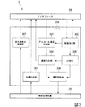
図3は、一実施形態によるアルコール濃度計測装置1のソフトウェア構成を示す概略ブロック図である。
CPU205は、補助記憶装置207が記憶するプログラムを実行することで、交換判定部301、曝露指示部302、アルコール濃度計測部303、遮断指示部304、計時部305、履歴更新部306、劣化度表示制御部307を備える。
FIG. 3 is a schematic block diagram illustrating a software configuration of the alcohol
The
交換判定部301は、補助記憶装置207が記憶するアルコールセンサ204の使用開始日時と、アルコールセンサ204の延べ使用時間とに基づいて、アルコールセンサ204を交換すべきか否かを判定する。具体的には、交換判定部301は、アルコールセンサ204の使用開始日時から現在時刻までの期間、すなわちアルコールセンサ204の使用期間が所定の閾値(例えば、1年)を超える場合に、アルコールセンサ204を交換すべきであると判定する。また、交換判定部301は、アルコールセンサ204の延べ使用時間、すなわちアルコールセンサ204が外気に曝露された時間に応じた値の総和が所定の閾値を超える場合に、アルコールセンサ204を交換すべきであると判定する。
The
曝露指示部302は、インタフェース208を介して圧力センサ202から呼気流路201内の圧力を読み出す。曝露指示部302は、呼気流路201内の圧力に基づいて、呼気流路201内に呼気が吹き込まれているか否かを判定する。曝露指示部302は、呼気流路201内に呼気が所定時間(例えば、5秒間)吹き込まれたときに、インタフェース208を介して電磁弁203に呼気流路201を開く指示を出力する。曝露指示部302による指示に従って電磁弁203が開くことで、アルコールセンサ204は外気に曝露される。
The
アルコール濃度計測部303は、インタフェース208を介してアルコールセンサ204からアルコールの濃度に応じた信号を取得する。アルコール濃度計測部303は、アルコールセンサ204から取得した信号のピーク値を特定する。アルコール濃度計測部303は、アルコールセンサ204から取得した信号の値が所定の閾値(例えば、ピーク値の20%)以下になるまで、信号が示す値を積算する。アルコール濃度計測部303は、信号のピーク値及び積算値に基づいて、呼気のアルコールの濃度を計測する。
本実施形態では、閾値としてピーク値の20%を用いることで、アルコールの濃度の計測に係る時間を5秒程度に抑えることができる。他方、閾値としてピーク値に対する相対的な値を用いず、絶対的な値を閾値として適用しても良い。この場合、アルコールセンサ204から取得した信号の値が閾値以下になるまでにかかる時間は、アルコールの濃度に対して単調増加する。
The alcohol
In the present embodiment, by using 20% of the peak value as the threshold value, the time for measuring the concentration of alcohol can be suppressed to about 5 seconds. On the other hand, an absolute value may be applied as the threshold value without using a relative value with respect to the peak value as the threshold value. In this case, the time taken for the value of the signal acquired from the
遮断指示部304は、アルコール濃度計測部303がアルコールの濃度の計測を終えると、当該計測結果に応じた復帰時間の経過後に、インタフェース208を介して電磁弁203に呼気流路201を閉じる指示を出力する。これは、アルコールセンサ204の白金触媒からアルコールが抜けるまで、アルコールセンサ204を外気に曝露するためである。復帰時間は、検出されたアルコールの濃度に対して単調非減少となる時間である。これは、アルコールの濃度が高いほど、アルコールセンサ204からアルコールが抜けるまでにかかる時間が長くなるためである。遮断指示部304による指示に従って電磁弁203が閉じることで、アルコールセンサ204は外気から遮断される。
When the alcohol
計時部305は、アルコールセンサ204の使用時間を計時する。アルコールセンサ204の使用時間とは、曝露指示部302が呼気流路201内に呼気が吹き込まれていると判定した時刻から、遮断指示部304が電磁弁203に呼気流路201を閉じる指示を出力する時刻までの時間である。
履歴更新部306は、計時部305が計時した時間を、補助記憶装置207が記憶するアルコールセンサ204の延べ使用時間に加算する。
劣化度表示制御部307は、補助記憶装置207から使用開始日時及び延べ使用時間を読み出し、これに基づいて算出したアルコールセンサ204の劣化の度合いを、ディスプレイ102に表示させる。
The
The
The deterioration level
次に、本実施形態に係るアルコール濃度計測装置1の動作について説明する。
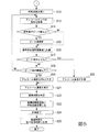
図4は、一実施形態によるアルコール濃度計測装置1の動作を示す第1のフローチャートである。
図5は、一実施形態によるアルコール濃度計測装置1の動作を示す第2のフローチャートである。
被験者による操作ボタン103の押下により、CPU205が起動する(ステップS1)。CPU205は、起動すると、補助記憶装置207が記憶するプログラムを実行する。
CPU205がプログラムを実行すると、交換判定部301は、補助記憶装置207が記憶するアルコールセンサ204の使用開始日時と、アルコールセンサ204の延べ使用時間を読み出す(ステップS2)。交換判定部301は、読み出した使用開始日時及び延べ使用時間に基づいて、アルコールセンサ204の使用期間が所定の閾値を超えたか、またはアルコールセンサ204の延べ使用時間が所定の閾値を超えたか否かを判定する(ステップS3)。
Next, operation | movement of the alcohol
FIG. 4 is a first flowchart showing the operation of the alcohol
FIG. 5 is a second flowchart showing the operation of the alcohol
When the
When the
交換判定部301は、アルコールセンサ204の使用期間が所定の閾値を超えたと判定した場合、またはアルコールセンサ204の延べ使用時間が所定の閾値を超えたと判定した場合(ステップS3:YES)、アルコールセンサ204を交換すべきであると判定する。交換判定部301は、アルコールセンサ204を交換すべきであると判定すると、インタフェース208を介してディスプレイ102にアルコールセンサ204の交換の通知を表示させる(ステップS4)。他方、交換判定部301は、アルコールセンサ204の使用期間が所定の閾値を超えていないと判定し、かつアルコールセンサ204の延べ使用時間が所定の閾値を超えていないと判定した場合(ステップS3:NO)、アルコールセンサ204の交換を要しないと判定する。
When the
ディスプレイ102が交換の通知を表示し、またはディスプレイ102交換判定部301がアルコールセンサ204の交換を要しないと判定すると、曝露指示部302は、インタフェース208を介して圧力センサ202から呼気流路201内の圧力を読み出す(ステップS5)。次に、曝露指示部302は、呼気流路201内の圧力が所定の閾値以上であるか否かを判定する(ステップS6)。
When the
曝露指示部302は、呼気流路201内の圧力が閾値以上であると判定した場合(ステップS6:YES)、マウスピース104を介して呼気流路201内に呼気が吹き込まれていると判定する。曝露指示部302が、呼気流路201内に呼気が吹き込まれていると判定すると、計時部305は、現在時刻からの経過時間の計時を開始する(ステップS7)。計時部305が既に経過時間を計時している場合は、計時を継続する。
When it is determined that the pressure in the
次に、曝露指示部302は、計時部305が計時している経過時間が所定の閾値に達したか否かを判定する(ステップS8)。曝露指示部302は、経過時間が閾値に達していないと判定した場合(ステップS8:NO)、ステップS5に戻り、呼気流路201内の圧力の判定を継続する。
Next, the
他方、ステップS6において曝露指示部302が、呼気流路201内の圧力が閾値未満であると判定した場合(ステップS6:NO)、曝露指示部302は、計時部305が経過時間の計時を行っているか否かを判定する(ステップS9)。曝露指示部302は、呼気流路201内の圧力が閾値未満であり、かつ計時部305が経過時間の計時を行っていない場合(ステップS9:NO)、被験者による呼気の吹き込みがなされていないと判定する。曝露指示部302は、呼気の吹き込みがなされていないと判定すると、ステップS5に戻り、呼気の吹き込みの判定を継続する。
On the other hand, when the
他方、曝露指示部302は、呼気流路201内の圧力が閾値未満であり、かつ計時部305が経過時間の計時を行っている場合(ステップS9:YES)、被験者による呼気の吹き込みが中断されたと判定する。曝露指示部302は、呼気の吹き込みが中断されたと判定すると、インタフェース208を介してディスプレイ102に呼気の吹き込みが中断されたことによるエラーの通知を表示させる(ステップS10)。また、計時部305は、経過時間の計時を終了し、経過時間をリセットする(ステップS11)。
On the other hand, when the pressure in the
ステップS8において、曝露指示部302が、経過時間が閾値に達したと判定した場合(ステップS8:YES)、曝露指示部302は、計測に十分な量の呼気が呼気流路201内に吹き込まれたと判定する。曝露指示部302は、計測に十分な量の呼気が吹き込まれたと判定すると、インタフェース208を介して電磁弁203に呼気流路201を開く指示を出力する(ステップS12)。
In step S8, when the
曝露指示部302が指示を出力すると、アルコール濃度計測部303は、インタフェース208を介してアルコールセンサ204からアルコールの濃度に応じた信号を取得する(ステップS13)。アルコール濃度計測部303は、アルコールセンサ204から取得した信号の値が、主記憶装置206が記憶する信号のピーク値より大きいか否かを判定する(ステップS14)。アルコール濃度計測部303は、取得した信号の値が、主記憶装置206が記憶するピーク値より大きいと判定した場合(ステップS14:YES)、主記憶装置206が記憶するピーク値を更新する(ステップS15)。他方、アルコール濃度計測部303は、取得した信号の値が主記憶装置206が記憶する最大値以下であると判定した場合(ステップS14:NO)、主記憶装置206が記憶する最大値を更新しない。次に、アルコール濃度計測部303は、アルコールセンサ204から取得した信号の値を、主記憶装置206が記憶する信号積算値に加算する(ステップS16)。
When the
次に、アルコール濃度計測部303は、取得した信号の値が、主記憶装置206が記憶するピーク値の20%以下であるか否かを判定する(ステップS17)。アルコール濃度計測部303は、取得した信号の値が、ピーク値の20%より大きいと判定した場合(ステップS17:NO)、信号の取得開始からの所定時間(例えば、1秒)の間に計測されたピーク値が所定の閾値以下であるか否かを判定する(ステップS18)。
Next, the alcohol
アルコール濃度計測部303は、取得した信号の値がピーク値の20%より大きく、かつピーク値が閾値より大きいと判定した場合(ステップS18:NO)、ステップS13に戻り、アルコールセンサ204からの信号の取得を継続する。他方、アルコール濃度計測部303は、取得した信号の値がピーク値の20%より大きく、かつピーク値が閾値より大きいと判定した場合(ステップS18:YES)、呼気にアルコールが含まれていないと判定する(ステップS19)。つまり、アルコール濃度計測部303は、呼気に含まれるアルコールの濃度が0%であると判定する。
When the alcohol
他方、ステップS17においてアルコール濃度計測部303が、取得した信号の値が所定の閾値以下であると判定した場合(ステップS17:YES)、アルコール濃度計測部303は、主記憶装置206が記憶するピーク値及び信号積算値に基づいて、呼気に含まれるアルコールの濃度を計測する(ステップS20)。
On the other hand, when the alcohol
アルコール濃度計測部303は、ステップS19またはステップS20でアルコールの濃度を計測すると、インタフェース208を介してディスプレイ102にアルコールの濃度を表示させる(ステップS21)。
When the alcohol
次に、遮断指示部304は、アルコール濃度計測部303が計測した濃度に基づいて、復帰時間を特定する(ステップS22)。本実施形態では、遮断指示部304は、濃度と復帰時間とを関連付けたテーブルに従って、復帰時間を特定する。当該テーブルにおいて、復帰時間は、検出されたアルコールの濃度に対して単調非減少となる時間である。遮断指示部304は、復帰時間を特定すると、当該復帰時間の経過後に、インタフェース208を介して電磁弁203に呼気流路201を閉じる指示を出力する(ステップS23)。
Next, the shut-off
遮断指示部304が指示を出力すると、計時部305は、経過時間の計時を終了する(ステップS24)。次に、履歴更新部306は、計時部305が計時した時間を、補助記憶装置207が記憶するアルコールセンサ204の延べ使用時間に加算する(ステップS25)。履歴更新部306が延べ使用時間を更新すると、計時部305は、計時した経過時間をリセットする。これにより、アルコール濃度計測装置1は、処理を終了し、CPU205への電力供給を終了する。
When the shut-off
上述した処理により、交換判定部301は、アルコールセンサ204の使用期間及びアルコールセンサ204の延べ使用時間に基づいて、アルコールセンサ204を交換すべきか否かの判定を行う。アルコールセンサ204の延べ使用時間は、アルコールセンサ204が外気に曝露された時間に応じた値の総和である。したがって、アルコール濃度計測装置1は、アルコールセンサ204が外気に曝露されることによって白金触媒の活性が低下したときに、交換の通知を行うことができる。
Through the processing described above, the
また、アルコールセンサ204が出力する電気信号の値が所定の閾値以下になるまでの時間及び待機時間は、呼気に含まれるアルコールの濃度に対して単調非減少となる時間である。つまり、アルコールセンサ204の延べ使用時間は、アルコールの濃度に応じた値の総和でもある。したがって、アルコール濃度計測装置1は、アルコールから分離された水素の反応により生じる水や、呼気に含まれるS(硫黄)等の成分によりアルコールセンサ204が劣化したときに、交換の通知を行うことができる。
In addition, the time until the value of the electric signal output from the
なお、アルコール濃度計測装置1は、起動している間、ディスプレイ102にアルコールセンサ204の劣化の度合いを表示する。
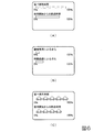
図6は、アルコールセンサの劣化の度合いの表示例を示す図である。
劣化度表示制御部307は、補助記憶装置207から使用開始日時及び延べ使用時間を読み出し、これに基づいてアルコールセンサ204の劣化の度合いを算出する。具体的には、劣化度表示制御部307は、延べ使用時間を使用時間の閾値で除算して得られる割合(アルコールセンサが外気に曝露された時間に応じた値の総和をアルコールセンサの交換の通知を行う所定の値で除算して得られる割合)と、使用開始日時からの経過時間を経過時間の閾値で除算して得られる割合とを、劣化の度合いとして算出する。なお、延べ使用時間を使用時間の閾値で除算して得られる割合は、アルコール濃度計測部303が計測したアルコールの濃度に応じた値の総和を、アルコールセンサ204の交換の通知を行う所定の値で除算して得られる割合と等価である。そして、劣化度表示制御部307は、算出した劣化の度合いをインタフェース208を介してディスプレイ102に表示させる。
The alcohol
FIG. 6 is a diagram illustrating a display example of the degree of deterioration of the alcohol sensor.
The deterioration level
劣化の度合いの表示例の1つとしては、図6(A)、(B)に示すように、使用開始日時からの経過時間の閾値に対する割合と延べ使用時間の閾値に対する割合とをそれぞれバーによって表す方法が挙げられる。図6(A)に示す例では、アルコールセンサ204の劣化が無いときにバーの長さが最長となり、アルコールセンサ204を交換すべきときにバーの長さが最短となる。図6(B)に示す例では、アルコールセンサ204の劣化が無いときにバーの長さが最短となり、アルコールセンサ204を交換すべきときにバーの長さが最長となる。
このとき、アルコールセンサ204の劣化の度合いによってバーの色を変化させても良い。例えば、アルコールセンサ204の延べ使用時間を使用時間の閾値で除算して得られる割合が25%未満である場合に緑色、当該割合が25%〜75%である場合に黄色、当該割合が75%以上である場合に赤色と、バーの色を変化させても良い。使用開始日時からの経過時間についても同様である。
また、バーの長さは経過時間や延べ使用時間に対して線形の値としても良いし、対数の値をとっても良い。なお、バーの長さとして対数の値をとることで、交換の必要性を強調させることができる。
As one example of display of the degree of deterioration, as shown in FIGS. 6A and 6B, the ratio of the elapsed time from the use start date and time to the threshold of the total usage time is indicated by a bar. The method of expressing is mentioned. In the example shown in FIG. 6A, the length of the bar becomes the longest when the
At this time, the color of the bar may be changed depending on the degree of deterioration of the
The length of the bar may be a linear value with respect to the elapsed time or the total usage time, or may be a logarithmic value. In addition, the necessity of exchange can be emphasized by taking the logarithm value as the length of the bar.
他の表示例としては、図6(C)に示すように、使用開始日時からの経過時間と延べ使用時間とをそれぞれ記号やアイコンの数によって表す方法が挙げられる。図6(C)に示す例では、アルコールセンサ204の劣化が無いときに記号またはアイコンの数が最多となり、アルコールセンサ204を交換すべきときに記号またはアイコンの数が最少(0個)となる。
また、劣化度表示制御部307は、単に使用開始日時からの経過時間の閾値に対する割合と延べ使用時間の閾値に対する割合を示す数値をディスプレイ102に表示させても良い。
As another display example, as shown in FIG. 6C, there is a method of representing the elapsed time from the use start date and time and the total use time by the number of symbols and icons, respectively. In the example shown in FIG. 6C, the number of symbols or icons is maximum when the
Further, the deterioration degree
以上、図面を参照して一実施形態について詳しく説明してきたが、具体的な構成は上述のものに限られることはなく、様々な設計変更等をすることが可能である。
例えば、本実施形態では、ガス濃度計測装置を、アルコール濃度計測装置1に実装する場合について説明したが、これに限られない。例えば、本発明に係るガス濃度計測装置の機能を、他のガス濃度計測装置に適用しても良い。他のガス濃度計測装置の例としては、呼気中のアセトン濃度を検出することで、体脂肪の燃焼度合いを計測する体脂肪燃焼量測定装置や、メチルメルカプタンなどの口臭要因ガスの濃度を計測する口臭検査装置などが挙げられる。また、本実施形態では、アルコールセンサ204が燃料電池方式のアルコールセンサである場合について説明したが、これに限られない。例えば、アルコール濃度計測装置1は、半導体方式のアルコールセンサを備えていても良い。
また、本実施形態では、計時部305が、呼気流路201内に呼気が吹き込まれた時刻からアルコール濃度の計測後、復帰時間が経過した時刻までの時間を計時し、その総和に基づいて交換の判定をする場合について説明したが、これに限られない。例えば、履歴更新部306は、曝露指示部302が呼気流路201を開く指示を出力してから遮断指示部304が呼気流路201を閉じる指示を出力するまでの時間を計測しても良い。
As described above, the embodiment has been described in detail with reference to the drawings. However, the specific configuration is not limited to that described above, and various design changes and the like can be made.
For example, in this embodiment, although the case where the gas concentration measuring device was mounted in the alcohol
Further, in the present embodiment, the
また、計時部305が計時する使用時間は、アルコール濃度計測部303が計測したアルコールの濃度に応じた値の一例でもある。他方、計時部305は、遮断判定部が特定した復帰時間や、アルコールセンサ204が出力する信号値が所定の閾値以下になるまでの時間を、アルコール濃度計測部303が計測したアルコールの濃度に応じた値として、計時しても良い。
Further, the usage time counted by the
また、履歴更新部306は、呼気流路201内に呼気が吹き込まれた時刻からエラーによって計時を終了する時刻までの時間を、アルコールセンサ204の延べ使用時間に加算しても良い。
In addition, the
また、本実施形態では、交換判定部301が、アルコールセンサ204が外気に曝露された時間に応じた値の一例として、アルコールセンサ204の使用時間に基づいて交換の判定を行う場合について説明したが、これに限られない。例えば、交換判定部301は、アルコールセンサ204が外気に曝露された時間に対して単調非減少する所定のパラメータを用いて交換の判定を行っても良い。
Further, in the present embodiment, the case where the
また、本実施形態では、アルコールセンサ204として燃料電池方式のものを用いる場合について説明したが、これに限られず、半導体方式や他の方式のアルコールセンサを用いても良い。
In this embodiment, the fuel cell type is used as the
また、本実施形態では、ディスプレイ102にアルコールセンサ204の劣化の度合いを表示する場合について説明したが、これに限られない。例えば、他の実施形態では、アルコール濃度計測装置1に接続された外部機器に、アルコールセンサ204の劣化の度合いを表示させても良い。この場合、アルコール濃度計測装置1がインタフェース208を介して外部機器であるPC(Personal Computer)に接続されると、アルコール濃度計測装置1は、補助記憶装置207が記憶する使用開始日時及び延べ使用時間をPCに転送する。そして、PCは、転送された使用開始日時及び延べ使用時間に基づいてアルコールセンサ204の劣化の度合いを表示する。また、アルコール濃度計測装置1が、劣化度表示制御部307が生成した劣化の度合いの表示画像をPCに転送し、PCが当該表示画像を表示しても良い。
Moreover, although this embodiment demonstrated the case where the degree of degradation of the
また、本実施形態では、使用開始日時に基づくアルコールセンサ204の劣化の度合いと延べ使用時間に基づく劣化の度合いとをディスプレイ102に表示する場合について説明したが、これに限られず、いずれか一方のみを表示させるものであっても良い。
In the present embodiment, the case where the degree of deterioration of the
なお、本実施形態において、主記憶装置206及び補助記憶装置207は、一時的でない有形の媒体の一例である。また、本実施形態では、プログラムが補助記憶装置207に記録されている場合について説明したが、これに限られない。例えば、プログラムは、補助記憶装置207以外の一時的でない有形の媒体に記録されていても良い。一時的でない有形の媒体の他の例としては、インタフェース208を介して接続される磁気ディスク、光磁気ディスク、CD−ROM、DVD−ROM、半導体メモリ等が挙げられる。また、プログラムは、通信回線によってコンピュータに配信されるものであっても良い。この場合、配信を受けたコンピュータが当該プログラムを主記憶装置206に展開し、上記処理を実行する。
In the present embodiment, the
また、当該プログラムは、前述した機能の一部を実現するためのものであっても良い。さらに、当該プログラムは、前述した機能を補助記憶装置207に既に記憶されている他のプログラムとの組み合わせで実現するもの、いわゆる差分ファイル(差分プログラム)であっても良い。
The program may be for realizing a part of the functions described above. Further, the program may be a so-called difference file (difference program) that realizes the above-described function in combination with another program already stored in the
1…アルコール濃度計測装置 101…筐体 102…ディスプレイ 103…操作ボタン 104…マウスピース 105…ソケット 201…呼気流路 202…圧力センサ 203…電磁弁 204…アルコールセンサ 205…CPU 206…主記憶装置 207…補助記憶装置 208…インタフェース 301…交換判定部 302…曝露指示部 303…アルコール濃度計測部 304…遮断指示部 305…計時部 306…履歴更新部
DESCRIPTION OF
Claims (10)
前記ガスの濃度に応じた電気信号を出力するガスセンサと、
前記ガスの濃度を計測するときに、前記ガスセンサを外気に曝露させる曝露機構と、
前記ガスセンサが外気に曝露されているときに前記ガスセンサが出力する電気信号に基づいて被験者の呼気に含まれる前記ガスの濃度を計測する計測部と、
前記ガスセンサが外気に曝露された時間に応じた値の総和が所定の値を超える場合に、前記ガスセンサの交換の通知を行う通知部と
を備えることを特徴とするガス濃度計測装置。 A gas concentration measuring device for measuring the concentration of a gas to be measured,
A gas sensor that outputs an electrical signal corresponding to the concentration of the gas;
An exposure mechanism for exposing the gas sensor to outside air when measuring the concentration of the gas;
A measurement unit that measures the concentration of the gas contained in the exhalation of a subject based on an electrical signal output by the gas sensor when the gas sensor is exposed to outside air;
A gas concentration measuring device comprising: a notification unit that notifies the replacement of the gas sensor when the sum of the values according to the time when the gas sensor is exposed to the outside air exceeds a predetermined value.
ことを特徴とする請求項1に記載のガス濃度計測装置。 The gas concentration measuring device according to claim 1, wherein the exposure mechanism exposes the gas sensor to outside air during a time period in which the concentration of the gas is not monotonously non-decreasing.
ことを特徴とする請求項2に記載のガス濃度計測装置。 The exposure mechanism ends the exposure of the gas sensor after the measurement unit measures the concentration of the gas and after a time that is monotonously non-decreasing with respect to the concentration of the gas measured by the measurement unit has elapsed. The gas concentration measuring apparatus according to claim 2, wherein:
前記計測部は、電気信号の積算値に基づいて前記ガスの濃度の計測を行う
ことを特徴とする請求項2または請求項3に記載のガス濃度計測装置。 The exposure mechanism continues the exposure of the gas sensor until at least the value of the electrical signal output by the gas sensor becomes a predetermined threshold value or less,
The gas concentration measuring device according to claim 2, wherein the measuring unit measures the concentration of the gas based on an integrated value of an electric signal.
を備えることを特徴とする請求項1から請求項4の何れか1項に記載のガス濃度計測装置。 A deterioration degree display control unit for displaying a ratio obtained by dividing a sum of values according to a time when the gas sensor is exposed to outside air by a predetermined value for notifying the replacement of the gas sensor. The gas concentration measuring device according to any one of claims 1 to 4.
前記ガスの濃度に応じた電気信号を出力するガスセンサと、
前記ガスセンサが出力する電気信号に基づいて前記ガスの濃度を計測する計測部と、
前記計測部が計測した前記ガスの濃度に応じた値の総和が所定の値を超える場合に、前記ガスセンサの交換の通知を行う通知部と
を備えることを特徴とするガス濃度計測装置。 A gas concentration measuring device for measuring the concentration of a gas to be measured,
A gas sensor that outputs an electrical signal corresponding to the concentration of the gas;
A measurement unit that measures the concentration of the gas based on an electrical signal output by the gas sensor;
A gas concentration measurement device comprising: a notification unit that notifies the replacement of the gas sensor when the sum of the values according to the gas concentration measured by the measurement unit exceeds a predetermined value.
を備えることを特徴とする請求項6に記載のガス濃度計測装置。 A deterioration degree display control unit for displaying a ratio obtained by dividing a sum of values according to gas concentration measured by the measurement unit by a predetermined value for notifying replacement of the gas sensor; The gas concentration measuring device according to claim 6.
ことを特徴とする請求項1から請求項7の何れか1項に記載のガス濃度計測装置。 The gas concentration measurement according to any one of claims 1 to 7, wherein the notification unit notifies the replacement of the gas sensor when a usage period of the gas sensor exceeds a predetermined value. apparatus.
前記ガスセンサが外気に曝露された時間の総和が所定の値を超えるか否かを判定するステップと、
前記外気に曝露された時間に応じた値の総和が所定の値を超える場合に、前記ガスセンサの交換の通知を行うステップと
を備えることを特徴とする交換通知方法。 A gas sensor replacement notification method provided in a gas concentration measurement device that measures the concentration of a gas to be measured,
Determining whether the total amount of time the gas sensor has been exposed to outside air exceeds a predetermined value;
A notification of replacement of the gas sensor when the sum of values according to the time of exposure to the outside air exceeds a predetermined value.
前記ガスセンサが出力する電気信号に基づいて前記ガスの濃度を計測するステップと、
前記計測部が計測した前記ガスの濃度に応じた値の総和が所定の値を超えるか否かを判定するステップと、
前記計測部が計測した前記ガスの濃度に応じた値の総和が所定の値を超える場合に、前記ガスセンサの交換の通知を行うステップと
を備えることを特徴とする交換通知方法。 A gas sensor replacement notification method provided in a gas concentration measurement device that measures the concentration of a gas to be measured,
Measuring the concentration of the gas based on an electrical signal output by the gas sensor;
Determining whether the sum of values according to the concentration of the gas measured by the measuring unit exceeds a predetermined value;
A replacement notification method comprising: notifying replacement of the gas sensor when a sum of values according to the concentration of the gas measured by the measurement unit exceeds a predetermined value.
Priority Applications (4)
| Application Number | Priority Date | Filing Date | Title |
|---|---|---|---|
| JP2013258283A JP6229836B2 (en) | 2013-12-13 | 2013-12-13 | Gas concentration measuring device |
| EP14195591.4A EP2891883A1 (en) | 2013-12-13 | 2014-12-01 | Gas concentration measurement apparatus and replacement notification method |
| CN201410749165.9A CN104714039A (en) | 2013-12-13 | 2014-12-09 | Gas concentration measurement apparatus and replacement notification method |
| RU2014150360A RU2014150360A (en) | 2013-12-13 | 2014-12-11 | DEVICE FOR MEASURING GAS CONCENTRATION AND METHOD FOR NOTIFICING REPLACEMENT |
Applications Claiming Priority (1)
| Application Number | Priority Date | Filing Date | Title |
|---|---|---|---|
| JP2013258283A JP6229836B2 (en) | 2013-12-13 | 2013-12-13 | Gas concentration measuring device |
Publications (2)
| Publication Number | Publication Date |
|---|---|
| JP2015114274A true JP2015114274A (en) | 2015-06-22 |
| JP6229836B2 JP6229836B2 (en) | 2017-11-15 |
Family
ID=51999323
Family Applications (1)
| Application Number | Title | Priority Date | Filing Date |
|---|---|---|---|
| JP2013258283A Active JP6229836B2 (en) | 2013-12-13 | 2013-12-13 | Gas concentration measuring device |
Country Status (4)
| Country | Link |
|---|---|
| EP (1) | EP2891883A1 (en) |
| JP (1) | JP6229836B2 (en) |
| CN (1) | CN104714039A (en) |
| RU (1) | RU2014150360A (en) |
Cited By (8)
| Publication number | Priority date | Publication date | Assignee | Title |
|---|---|---|---|---|
| JP2017116430A (en) * | 2015-12-24 | 2017-06-29 | 株式会社タニタ | Expiratory component measuring device |
| JP2018124170A (en) * | 2017-01-31 | 2018-08-09 | パナソニックIpマネジメント株式会社 | Gas sensor |
| KR20190142789A (en) * | 2018-06-18 | 2019-12-30 | (주)센텍코리아 | Breath alcohol analyzer capable of estimating remaining life of a sensing part |
| JP2020099815A (en) * | 2015-12-21 | 2020-07-02 | 株式会社三共 | Game machine |
| JP2020099816A (en) * | 2015-12-21 | 2020-07-02 | 株式会社三共 | Game machine |
| JP2023121044A (en) * | 2022-02-18 | 2023-08-30 | 株式会社タニタ | Breath component measurement device, breath component measurement system, breath component measurement method, and breath component measurement program |
| JP2024036070A (en) * | 2022-09-05 | 2024-03-15 | 鈴与シンワート株式会社 | Portable breathalyzer, information management system, information management method and program |
| JP2024066114A (en) * | 2022-11-01 | 2024-05-15 | 三菱電機株式会社 | Wireless Sensor Device |
Families Citing this family (3)
| Publication number | Priority date | Publication date | Assignee | Title |
|---|---|---|---|---|
| DE102017206878B4 (en) * | 2017-04-25 | 2025-04-03 | Robert Bosch Gmbh | Method, control unit and device for detecting a gaseous substance in a gas mixture |
| US11315686B2 (en) | 2018-08-07 | 2022-04-26 | Vivante Health, Inc. | Individualized care management system based on digestive activity |
| EP4206667A4 (en) * | 2020-12-04 | 2023-12-13 | Shenzhen Everbest Machinery Industry Co., Ltd. | ALCOHOL DETECTOR BASED ON AIR BLOWING METHOD, AND INTELLIGENT DEVICE |
Citations (8)
| Publication number | Priority date | Publication date | Assignee | Title |
|---|---|---|---|---|
| JPS5319888A (en) * | 1976-08-08 | 1978-02-23 | Nippon Soken | Deterioration detecting apparatus for oxygen concentration detector |
| JPH11142360A (en) * | 1997-11-07 | 1999-05-28 | Harman Co Ltd | Unburnt-gas-concentration detecting sensor and burning apparatus provided with the sensor |
| JP2003524149A (en) * | 1999-06-08 | 2003-08-12 | オリディオン ブレシド リミティド | Gas analyzer verification test equipment |
| JP2004093203A (en) * | 2002-08-29 | 2004-03-25 | Honda Motor Co Ltd | Gas sensor status determination device |
| JP2005077144A (en) * | 2003-08-28 | 2005-03-24 | Fis Inc | Exhalation component analyzer |
| JP2008281514A (en) * | 2007-05-14 | 2008-11-20 | Tanita Corp | Gas composition measuring instrument |
| JP2009058502A (en) * | 2006-12-28 | 2009-03-19 | Toyota Central R&D Labs Inc | Gas detection method and gas detection apparatus |
| JP4613184B2 (en) * | 2007-05-23 | 2011-01-12 | 東海電子株式会社 | Alcohol detection system |
Family Cites Families (6)
| Publication number | Priority date | Publication date | Assignee | Title |
|---|---|---|---|---|
| KR19990084486A (en) * | 1998-05-07 | 1999-12-06 | 윤종용 | How to determine when to replace the filter of the air purifier |
| TW456130B (en) * | 1999-04-23 | 2001-09-21 | Tanita Seisakusho Kk | Exhalation gaseous component gauge and a cellular phone equipped with function of measuring gaseous components |
| CN100437104C (en) * | 2005-05-18 | 2008-11-26 | 深圳市奥特迅传感技术有限公司 | Gas sensor, gas detector, and self-testing and self-correcting method therefor |
| BRPI0908236A2 (en) * | 2008-02-14 | 2015-07-21 | Toyota Motor Co Ltd | Gas Concentration Detector |
| CN102858241B (en) * | 2010-05-17 | 2015-06-10 | 艾克雷泽私人有限公司 | Handheld Random Breath Test Device |
| EP2498091A1 (en) * | 2011-03-09 | 2012-09-12 | Sensa Bues AB | A vehicle interlocking system and method based on detection of analytes in exhaled breath |
-
2013
- 2013-12-13 JP JP2013258283A patent/JP6229836B2/en active Active
-
2014
- 2014-12-01 EP EP14195591.4A patent/EP2891883A1/en not_active Withdrawn
- 2014-12-09 CN CN201410749165.9A patent/CN104714039A/en active Pending
- 2014-12-11 RU RU2014150360A patent/RU2014150360A/en not_active Application Discontinuation
Patent Citations (8)
| Publication number | Priority date | Publication date | Assignee | Title |
|---|---|---|---|---|
| JPS5319888A (en) * | 1976-08-08 | 1978-02-23 | Nippon Soken | Deterioration detecting apparatus for oxygen concentration detector |
| JPH11142360A (en) * | 1997-11-07 | 1999-05-28 | Harman Co Ltd | Unburnt-gas-concentration detecting sensor and burning apparatus provided with the sensor |
| JP2003524149A (en) * | 1999-06-08 | 2003-08-12 | オリディオン ブレシド リミティド | Gas analyzer verification test equipment |
| JP2004093203A (en) * | 2002-08-29 | 2004-03-25 | Honda Motor Co Ltd | Gas sensor status determination device |
| JP2005077144A (en) * | 2003-08-28 | 2005-03-24 | Fis Inc | Exhalation component analyzer |
| JP2009058502A (en) * | 2006-12-28 | 2009-03-19 | Toyota Central R&D Labs Inc | Gas detection method and gas detection apparatus |
| JP2008281514A (en) * | 2007-05-14 | 2008-11-20 | Tanita Corp | Gas composition measuring instrument |
| JP4613184B2 (en) * | 2007-05-23 | 2011-01-12 | 東海電子株式会社 | Alcohol detection system |
Cited By (12)
| Publication number | Priority date | Publication date | Assignee | Title |
|---|---|---|---|---|
| JP2020099815A (en) * | 2015-12-21 | 2020-07-02 | 株式会社三共 | Game machine |
| JP2020099816A (en) * | 2015-12-21 | 2020-07-02 | 株式会社三共 | Game machine |
| JP2017116430A (en) * | 2015-12-24 | 2017-06-29 | 株式会社タニタ | Expiratory component measuring device |
| JP2018124170A (en) * | 2017-01-31 | 2018-08-09 | パナソニックIpマネジメント株式会社 | Gas sensor |
| US11933752B2 (en) | 2017-01-31 | 2024-03-19 | Nuvoton Technology Corporation Japan | Gas sensor and fuel cell vehicle |
| KR20190142789A (en) * | 2018-06-18 | 2019-12-30 | (주)센텍코리아 | Breath alcohol analyzer capable of estimating remaining life of a sensing part |
| KR102136004B1 (en) * | 2018-06-18 | 2020-07-22 | (주)센텍코리아 | Breath alcohol analyzer capable of estimating remaining life of a sensing part |
| JP2023121044A (en) * | 2022-02-18 | 2023-08-30 | 株式会社タニタ | Breath component measurement device, breath component measurement system, breath component measurement method, and breath component measurement program |
| JP7829215B2 (en) | 2022-02-18 | 2026-03-13 | 株式会社タニタ | Exhaled breath component measuring device, exhaled breath component measuring system, exhaled breath component measuring method, and exhaled breath component measuring program |
| JP2024036070A (en) * | 2022-09-05 | 2024-03-15 | 鈴与シンワート株式会社 | Portable breathalyzer, information management system, information management method and program |
| JP7645847B2 (en) | 2022-09-05 | 2025-03-14 | 鈴与シンワート株式会社 | Portable breathalyzer, information management system, information management method and program |
| JP2024066114A (en) * | 2022-11-01 | 2024-05-15 | 三菱電機株式会社 | Wireless Sensor Device |
Also Published As
| Publication number | Publication date |
|---|---|
| JP6229836B2 (en) | 2017-11-15 |
| CN104714039A (en) | 2015-06-17 |
| EP2891883A1 (en) | 2015-07-08 |
| RU2014150360A (en) | 2016-07-10 |
Similar Documents
| Publication | Publication Date | Title |
|---|---|---|
| JP6229836B2 (en) | Gas concentration measuring device | |
| CN1681435B (en) | Apparatus and method for diagnostic gas analysis | |
| US9974910B2 (en) | Systems and methods for compensating long term sensitivity drift of electrochemical gas sensors exposed to nitric oxide | |
| RU2666590C2 (en) | Mouthpiece for accurate detection of exhaled no | |
| JP3782823B2 (en) | Method for examining the action of a respiratory device | |
| JP5818888B2 (en) | Biogas detection device and biogas detection method | |
| CN105555190B (en) | Breast rail and training component | |
| US20140377877A1 (en) | Concentration measurements with a mobile device | |
| WO2010094967A1 (en) | Apparatus and method for breath testing | |
| JP2014522973A5 (en) | ||
| KR20220123086A (en) | Respiratory sensor measurement method and device | |
| CN110313914A (en) | Gas detecting system | |
| US10792521B2 (en) | Controller for, and method of, controlling a breathing apparatus | |
| CN101657724B (en) | measuring device | |
| JP2015150153A (en) | Body change evaluation apparatus, method, and program | |
| JP2015102531A (en) | Gas concentration measuring device, notification method and program | |
| JP2018087788A (en) | Expiratory component measurement device and abnormality determination method | |
| DE102015210622A1 (en) | Biological gas detection device, method, and program | |
| KR20160107752A (en) | Wearable device and system for monitoring user | |
| JP7353991B2 (en) | Breath component testing device | |
| JP2025156552A (en) | Exhaled breath component measuring device and abnormality determination method | |
| JP2020517951A (en) | Method, controller and device for detecting gaseous substances in a gas mixture | |
| CN111683708B (en) | Ventilator equipment | |
| JP7260395B2 (en) | Breath component test device | |
| JP2015167575A (en) | Body fat burning state determination device, method, and program |
Legal Events
| Date | Code | Title | Description |
|---|---|---|---|
| A621 | Written request for application examination |
Free format text: JAPANESE INTERMEDIATE CODE: A621 Effective date: 20160509 |
|
| A131 | Notification of reasons for refusal |
Free format text: JAPANESE INTERMEDIATE CODE: A131 Effective date: 20170314 |
|
| A521 | Request for written amendment filed |
Free format text: JAPANESE INTERMEDIATE CODE: A523 Effective date: 20170508 |
|
| TRDD | Decision of grant or rejection written | ||
| A01 | Written decision to grant a patent or to grant a registration (utility model) |
Free format text: JAPANESE INTERMEDIATE CODE: A01 Effective date: 20170912 |
|
| A61 | First payment of annual fees (during grant procedure) |
Free format text: JAPANESE INTERMEDIATE CODE: A61 Effective date: 20171003 |
|
| R150 | Certificate of patent or registration of utility model |
Ref document number: 6229836 Country of ref document: JP Free format text: JAPANESE INTERMEDIATE CODE: R150 |
|
| R250 | Receipt of annual fees |
Free format text: JAPANESE INTERMEDIATE CODE: R250 |
|
| R250 | Receipt of annual fees |
Free format text: JAPANESE INTERMEDIATE CODE: R250 |
|
| R250 | Receipt of annual fees |
Free format text: JAPANESE INTERMEDIATE CODE: R250 |
|
| R250 | Receipt of annual fees |
Free format text: JAPANESE INTERMEDIATE CODE: R250 |
|
| R250 | Receipt of annual fees |
Free format text: JAPANESE INTERMEDIATE CODE: R250 |
|
| R250 | Receipt of annual fees |
Free format text: JAPANESE INTERMEDIATE CODE: R250 |