JP2015114252A - Fuel level measuring device - Google Patents
Fuel level measuring device Download PDFInfo
- Publication number
- JP2015114252A JP2015114252A JP2013257754A JP2013257754A JP2015114252A JP 2015114252 A JP2015114252 A JP 2015114252A JP 2013257754 A JP2013257754 A JP 2013257754A JP 2013257754 A JP2013257754 A JP 2013257754A JP 2015114252 A JP2015114252 A JP 2015114252A
- Authority
- JP
- Japan
- Prior art keywords
- pressure
- fuel
- inside air
- volume
- adjustment
- Prior art date
- Legal status (The legal status is an assumption and is not a legal conclusion. Google has not performed a legal analysis and makes no representation as to the accuracy of the status listed.)
- Pending
Links
Images
Landscapes
- Measurement Of Levels Of Liquids Or Fluent Solid Materials (AREA)
Abstract
【課題】燃料タンク内における燃料の液面変化に影響されることなく燃料残量を高精度に計測し得る燃料残量計測装置を提供する。【解決手段】制御回路23にて実施される燃料残量計測処理において制御される減圧ポンプ22により燃料タンク10内の内圧Pを予め決められた開始圧力P1から目標圧力P2まで変化させるために要する調整度合いに応じて燃料タンク10内にて内気Gが占める内気体積V1が求められる。そして、この求められた内気体積V1から演算される燃料タンク10内にて燃料Fが占める体積V2に基づいて、燃料残量が計測される。【選択図】図2A fuel remaining amount measuring apparatus capable of measuring a remaining amount of fuel with high accuracy without being affected by a change in the fuel level in a fuel tank. It is necessary to change an internal pressure P in a fuel tank 10 from a predetermined start pressure P1 to a target pressure P2 by a pressure reducing pump 22 controlled in a fuel remaining amount measurement process performed by a control circuit 23. The inside air volume V1 occupied by the inside air G in the fuel tank 10 is determined according to the degree of adjustment. Then, the remaining amount of fuel is measured based on the volume V2 occupied by the fuel F in the fuel tank 10 calculated from the determined inside air volume V1. [Selection] Figure 2
Description
本発明は、燃料タンク内の燃料残量を計測する燃料残量計測装置に関するものである。 The present invention relates to a fuel remaining amount measuring device that measures the remaining amount of fuel in a fuel tank.
燃料タンク内の燃料残量を計測する方法として、燃料タンク内に設けられたフロートの上下量を可変抵抗(ポテンショメータ)により抵抗値に変換し、この抵抗値の上下動によって計測する手段がある。この計測手段に関する技術としては、例えば、下記特許文献1に開示される燃料液面検出装置が知られている。
As a method of measuring the remaining amount of fuel in the fuel tank, there is means for converting the vertical amount of the float provided in the fuel tank into a resistance value by a variable resistance (potentiometer) and measuring the resistance value by vertical movement. As a technique relating to this measuring means, for example, a fuel level detecting device disclosed in
この燃料液面検出装置では、球状のフロートを、このフロートを内接させつつ移動可能に案内するガイドの内部で燃料の液面の変位に追従して浮動させ、フロートの表面に設けられた導電体からなる可動接点部が、ガイドの内面に延設された可変抵抗部に接触するように構成されている。これにより、フロートがスムーズにガイドの内部を移動して可変抵抗部に接触することとなり、可変抵抗部の回路抵抗値がより確実に検知されるため、燃料の液面の高さを精度良く検出することができる。 In this fuel level detecting device, a spherical float is floated in accordance with the displacement of the fuel level inside a guide that movably guides the float while being inscribed, and a conductive material provided on the surface of the float. A movable contact portion made of a body is configured to contact a variable resistance portion extending on the inner surface of the guide. As a result, the float moves smoothly inside the guide and comes into contact with the variable resistance portion, and the circuit resistance value of the variable resistance portion is detected more reliably, so the level of the fuel level is accurately detected. can do.
ところで、上記特許文献1に開示されるように燃料の液面の高さをフロートの上下動に応じて計測する構成では、燃料の液面の一点を計測することとなる。このため、燃料タンクの傾きに応じて燃料の液面もが傾くと、この液面の傾きに応じてフロートが上下動してしまい、燃料残量の計測精度が低下してしまうという問題がある。特に、山道を走行している場合など、頻繁に燃料タンクが傾く場合には、この問題が顕著になる。
By the way, in the structure which measures the height of the liquid level of a fuel according to the vertical movement of a float as disclosed by the said
本発明は、上述した課題を解決するためになされたものであり、その目的とするところは、燃料タンク内における燃料の液面変化に影響されることなく燃料残量を高精度に計測し得る燃料残量計測装置を提供することにある。 The present invention has been made to solve the above-described problems, and an object of the present invention is to measure the remaining amount of fuel with high accuracy without being affected by the change in the fuel level in the fuel tank. The object is to provide a fuel remaining amount measuring device.
上記目的を達成するため、特許請求の範囲の請求項1に記載の発明は、燃料(F)が貯留される燃料タンク(10)内の燃料残量を計測する燃料残量計測装置(20,20a)であって、前記燃料タンク内の内気(G)の圧力(P)を検出する圧力検出手段(21)と、前記内気の圧力(P)を調整する圧力調整手段(22,30〜32,34)と、前記圧力調整手段を制御する圧力制御手段(23)と、前記燃料残量を計測する計測手段(23)と、を備え、前記計測手段は、前記圧力制御手段にて制御される前記圧力調整手段により前記内気の圧力を予め決められた開始圧力(P1)から目標圧力(P2)まで変化させるために要する調整度合い(t,N)に応じて前記燃料タンク内にて前記内気が占める体積(V1)を求め、前記内気の体積から演算される前記燃料タンク内にて前記燃料が占める体積(V2)に基づいて前記燃料残量を計測することを特徴とする。
なお、特許請求の範囲および上記手段の括弧内の符号は、後述する実施形態に記載の具体的手段との対応関係を示すものである。
In order to achieve the above object, the invention according to
In addition, the code | symbol in the parenthesis of a claim and the said means shows a corresponding relationship with the specific means as described in embodiment mentioned later.
請求項1の発明では、圧力制御手段にて制御される圧力調整手段により燃料タンク内の内気の圧力を予め決められた開始圧力から目標圧力まで変化させるために要する調整度合いに応じて燃料タンク内にて内気が占める体積が求められる。そして、この求められた内気の体積から演算される燃料タンク内にて燃料が占める体積に基づいて、燃料残量が計測される。 According to the first aspect of the present invention, the internal pressure of the fuel tank is adjusted according to the degree of adjustment required to change the pressure of the inside air in the fuel tank from the predetermined start pressure to the target pressure by the pressure adjusting means controlled by the pressure control means. The volume occupied by the inside air is determined. Then, the remaining amount of fuel is measured based on the volume occupied by the fuel in the fuel tank calculated from the volume of the obtained inside air.
燃料タンク内の内気の体積に応じて、内気の圧力を圧力変化させるために要する調整度合い(例えば、調整時間や調整回数)が変化する。例えば、燃料タンク内の内気の体積が比較的大きい場合には圧力変化させる体積が大きくなることから必要な調整度合いが大きくなり、燃料タンク内の内気の体積が比較的小さい場合には圧力変化させる体積が小さくなることから必要な調整度合いが小さくなる。 The degree of adjustment (for example, adjustment time or the number of adjustments) required to change the pressure of the inside air changes according to the volume of the inside air in the fuel tank. For example, if the volume of the inside air in the fuel tank is relatively large, the volume for changing the pressure becomes large, so that the necessary adjustment degree becomes large. If the volume of the inside air in the fuel tank is relatively small, the pressure is changed. Since the volume is reduced, the necessary degree of adjustment is reduced.
すなわち、内気の圧力に関する調整度合いに応じて燃料タンク内の内気の体積を求めることができ、この内気の体積から演算される燃料の体積に基づいて燃料残量を計測することができる。このような構成では、燃料タンク内にて燃料の液面が変化しても内気の圧力は変化しないため、燃料タンク内における燃料の液面変化に影響されることなく燃料残量を高精度に計測することができる。 That is, the volume of the inside air in the fuel tank can be obtained according to the degree of adjustment relating to the pressure of the inside air, and the remaining amount of fuel can be measured based on the volume of fuel calculated from the volume of the inside air. In such a configuration, even if the fuel level changes in the fuel tank, the pressure of the inside air does not change, so the remaining amount of fuel can be accurately determined without being affected by the change in the fuel level in the fuel tank. It can be measured.
[第1実施形態]
以下、本発明に係る燃料残量計測装置を具現化した第1実施形態について、図面を参照して説明する。
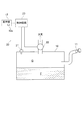
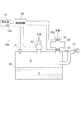
本実施形態に係る燃料残量計測装置20は、車両の内燃機関へ供給する燃料Fを貯留する燃料タンク10に搭載され、燃料タンク10内の燃料残量を計測する計測装置として構成されている。燃料タンク10は、給油口11を介して供給される燃料Fが貯留されるように構成されている。
[First Embodiment]
Hereinafter, a first embodiment in which a fuel remaining amount measuring apparatus according to the present invention is embodied will be described with reference to the drawings.
The fuel remaining
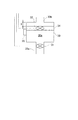
燃料残量計測装置20は、図1に示すように、センサ21と、減圧ポンプ22と、制御回路23とを備えている。センサ21は、燃料タンク10内の内気Gの圧力(以下、内圧Pともいう)と内気Gの温度(以下、内気温度Tともいう)との双方を検出する公知のセンサであって、検出した内圧Pおよび内気温度Tに応じた信号を制御回路23に出力するように構成されている。なお、センサ21は、「圧力検出手段」および「温度検出手段」の一例に相当し得る。
As shown in FIG. 1, the fuel remaining
減圧ポンプ22は、制御回路23により駆動制御されるポンプモータ(図示略)の駆動に応じて燃料タンク10内の内圧Pを調整する圧力調整手段として機能するものである。この減圧ポンプ22は、燃料タンク10内の内気Gを大気に放出するように駆動することで、内圧Pを減圧するように構成されている。
The
上述したセンサ21および減圧ポンプ22は、燃料タンク10に貯留される燃料Fが外部へリークしているか否かをチェックする公知のリークチェック装置に用いられる圧力センサおよびポンプと同じ機能を有するように構成されている。すなわち、リークチェック装置を車載する車両であれば圧力センサおよび減圧ポンプをリークチェック装置のものと共用することができる。なお、上記リークチェック装置としては、例えば、特開2004−263676号公報や特開2004−028060号公報にて開示されるリークチェック装置が知られている。
The
制御回路23は、CPU、ROMおよびRAMなどから構成されたマイクロコンピュータおよび周辺回路などから構成されており、後述する燃料残量計測処理を実施することで、燃料タンク10内の燃料残量を計測する計測手段として機能する。そして、制御回路23は、計測された燃料残量に基づいて燃料残量を表示する表示機12の表示を制御する表示信号を生成し、当該表示機12に出力する。また、制御回路23のメモリ等には、予め減圧ポンプ22の単位時間当たりの仕事量のデータが記憶されている。なお、制御回路23は、「圧力制御手段」の一例に相当し得る。
The
表示機12は、燃料タンク10に貯留されている燃料Fの燃料残量を視認者に報知するための装置である。表示機12は、数字及び文字等が形成された文字盤、当該文字盤の数字を指す指針、及び指針を回転させるステッピングモータ等によって構成されている。ステッピングモータは、制御回路23から入力される表示信号に基づいて指針を回転させるように機能する。これにより、表示機12は、燃料残量を示す表示を形成するように機能する。また、表示機12には、後述するエラー情報を報知する報知手段として、警告灯12aが設けられている。
The
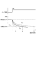
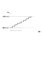
次に、本実施形態における燃料残量の計測について、図2〜図4を用いて詳細に説明する。なお、図2は、内気体積V1と調整時間tとの関係を説明する説明図である。図3は、第1実施形態において制御回路23にて実施される燃料残量計測処理の流れを例示するフローチャートである。図4は、内気温度Tに応じて設定された調整時間tと内気体積V1との関係を例示するマップである。
Next, the measurement of the remaining amount of fuel in the present embodiment will be described in detail with reference to FIGS. FIG. 2 is an explanatory diagram for explaining the relationship between the inside air volume V1 and the adjustment time t. FIG. 3 is a flowchart illustrating the flow of the remaining fuel amount measurement process performed by the
燃料タンク10内にて内気Gが占める体積(以下、内気体積V1ともいう)に応じて、内圧Pを圧力変化させるために要する圧力調整手段の調整度合いが変化する。例えば、図2に例示するように、内気体積がV1aとなる燃料残量の状態で減圧ポンプ22を予め決められた所定の出力で駆動することで、内圧Pを開始圧力P1から目標圧力P2まで変化させるために減圧ポンプ22を駆動させて調整する際に必要となる時間(以下、調整時間tともいう)をtaとする。
In accordance with the volume occupied by the inside air G in the fuel tank 10 (hereinafter also referred to as the inside air volume V1), the adjustment degree of the pressure adjusting means required for changing the internal pressure P changes. For example, as illustrated in FIG. 2, the internal pressure P is changed from the start pressure P1 to the target pressure P2 by driving the pressure-reducing
このとき、内気体積が上記V1aよりも大きなV1bである状態で上述のように圧力変化させる場合には、圧力変化させる体積が大きくなることから、内圧Pを開始圧力P1から目標圧力P2まで変化させるために要する調整時間tbがtaよりも長くなる。一方、内気体積が上記V1aよりも小さなV1cである状態で上述のように圧力変化させる場合には、圧力変化させる体積が小さくなることから、内圧Pを開始圧力P1から目標圧力P2まで変化させるために要する調整時間tcがtaよりも短くなる。 At this time, when the pressure is changed as described above in a state where the inside air volume is V1b larger than V1a, the volume to be changed is increased, and therefore the internal pressure P is changed from the start pressure P1 to the target pressure P2. The adjustment time tb required for this is longer than ta. On the other hand, when the pressure is changed as described above in a state where the inside air volume is V1c smaller than V1a, the volume to be changed is reduced, so that the internal pressure P is changed from the start pressure P1 to the target pressure P2. The adjustment time tc required for is shorter than ta.
そこで、本実施形態では、制御回路23にて実施される燃料残量計測処理にて、内圧Pに関する減圧ポンプ22の調整時間tに応じて燃料タンク10内の内気体積V1を求め、燃料タンク10の全容積Vからこの内気体積V1を除くことで燃料タンク10内にて燃料が占める体積V2を演算し、この体積V2に基づいて燃料残量を計測する。
Therefore, in the present embodiment, in the fuel remaining amount measurement process performed by the
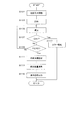
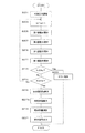
以下、本実施形態において、制御回路23にて実施される燃料残量計測処理について、図3および図4を用いて詳細に説明する。
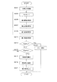
制御回路23による燃料残量計測処理が開始されると、まず、図3のステップS101に示す初期圧力調整処理がなされる。この処理では、センサ21にて検出される内圧Pが大気圧近傍に設定される開始圧力P1になるように減圧ポンプ22が駆動される。なお、開始圧力P1を大気圧と等しく設定することで、燃料タンク10内の大気解放により上記初期圧力調整処理を実施してその処理時間を短縮することもできる。また、本実施形態では、目標圧力P2は、例えば、開始圧力P1よりも20kPa低い値に設定されている。
Hereinafter, the remaining fuel amount measurement process performed by the
When the remaining fuel amount measurement process by the
次に、減圧ポンプ22が駆動する時間を調整時間tとして計時する計時処理が開始されるとともに(S103)、減圧ポンプ22が上記所定の出力で駆動することで、燃料タンク10内が減圧される(S105)。なお、上記ステップS103を実施する制御回路23は、「計時手段」の一例に相当し得る。
Next, a time measurement process is started in which the time during which the
この減圧ポンプ22による減圧は、センサ21にて検出される内圧Pが目標圧力P2に到達するまで継続される(S109でNo)。そして、調整時間tが規定時間toに到達する前に(S107でNo)、センサ21にて検出される内圧Pが目標圧力P2に到達すると(S109でYes)、ステップS111に示す内気体積算出処理がなされる。この処理では、内圧Pが目標圧力P2に到達したときの調整時間tに基づいて内気体積V1が求められる。
The pressure reduction by the
具体的には、図4に示すように、内気温度Tに応じて調整時間tと内気体積V1とが関係付けられたマップが制御回路23のメモリ等に予め記憶されており、内圧Pが目標圧力P2に到達したときの調整時間tとこのときにセンサ21により検出される内気温度Tとに基づいて内気体積V1が求められる。
Specifically, as shown in FIG. 4, a map in which the adjustment time t and the internal air volume V1 are related to the internal air temperature T is stored in advance in the memory or the like of the
なお、本実施形態では、内気温度Tを3つの区分(低温度Ta、通常温度Tb、高温度Tc)に区分けしてマップを構成しているが、これに限らず、さらに多くの区分に区分けしてもよい。また、内気温度Tの変動が少ない使用環境であれば、内気温度Tを考慮することなく調整時間tと内気体積V1とが関係付けられたマップを採用することもできる。 In this embodiment, the map is configured by dividing the inside air temperature T into three sections (low temperature Ta, normal temperature Tb, and high temperature Tc). However, the map is not limited to this, and the map is further divided into more sections. May be. Further, in a use environment in which the variation in the inside air temperature T is small, a map in which the adjustment time t and the inside air volume V1 are related can be adopted without considering the inside air temperature T.
上述のように内気体積V1が求められると、ステップS113に示す燃料残量演算処理がなされる。この処理では、燃料タンク10の全容積Vから内気体積V1を除くことで燃料が占める体積V2(=V−V1)が演算され、この演算結果に基づいて燃料残量が計測される。そして、計測された燃料残量に基づいて上記表示信号が生成されて表示機12に出力される(S115)。これにより、表示機12では、入力された表示信号に基づいて指針が回転し、燃料Fの燃料残量が視認者に報知される。
When the inside air volume V1 is obtained as described above, the remaining fuel amount calculation process shown in step S113 is performed. In this process, the volume V2 (= V−V1) occupied by the fuel is calculated by removing the inside air volume V1 from the total volume V of the
一方、経年劣化等に起因して減圧ポンプ22のポンプ性能が低下すると、内圧Pが目標圧力P2まで減圧されにくくなり燃料残量の計測精度が低下してしまう。そこで、本実施形態では、内圧Pが目標圧力P2に到達する前に(S109でNo)、調整時間tが規定時間toに到達すると(S107でYes)、経年劣化等に起因して減圧ポンプ22のポンプ性能が低下しているとして、ステップS117に示すエラー報知処理がなされる。なお、上記規定時間toは、燃料Fが入っていない状態での燃料タンク10の内圧Pが上記所定の出力で駆動する減圧ポンプ22により開始圧力P1から目標圧力P2に到達するまでにかかる時間よりも大きな値に設定されている。
On the other hand, when the pump performance of the
この処理では、燃料残量の計測精度が低下していることを示す情報が、エラー情報として報知される。なお、エラー情報の報知は、表示機12に設けられる警告灯12a等を所定の状態に点灯または点滅させることで実施される。
In this process, information indicating that the measurement accuracy of the remaining amount of fuel is reduced is notified as error information. The notification of the error information is performed by turning on or blinking a
以上説明したように、本実施形態に係る燃料残量計測装置20では、制御回路23にて実施される燃料残量計測処理において制御される減圧ポンプ22により燃料タンク10内の内圧Pを予め決められた開始圧力P1から目標圧力P2まで変化させるために要する調整度合いに応じて燃料タンク10内にて内気Gが占める内気体積V1が求められる。そして、この求められた内気体積V1から演算される燃料タンク10内にて燃料Fが占める体積V2に基づいて、燃料残量が計測される。
As described above, in the fuel remaining
このように、内気Gの内圧Pに関する調整度合いに応じて燃料タンク10内の内気Gの内気体積V1を求めることができ、この内気体積V1から演算される燃料の体積V2に基づいて燃料残量を計測することができる。このような構成では、燃料タンク10内にて燃料Fの液面が変化しても内気Gの内圧Pは変化しないため、燃料タンク10内における燃料Fの液面変化に影響されることなく燃料残量を高精度に計測することができる。
In this way, the internal air volume V1 of the internal air G in the
また、上記調整度合いとして、減圧ポンプ22により燃料タンク10内の内圧Pを開始圧力P1から目標圧力P2まで変化させるために要する調整時間tが採用され、この調整時間tに応じて内気Gの内気体積V1が求められるので、専用の測定機器等を設けることなく内気体積V1を算出することができる。
Further, as the degree of adjustment, an adjustment time t required for changing the internal pressure P in the
特に、調整時間tと内気体積V1との関係を示すマップが予め制御回路23のメモリ等に記憶されており、計時された調整時間tに応じて上記マップから内気体積V1が求められるため、内気体積V1を容易に算出することができる。なお、調整時間tに応じて上記マップから内気体積V1を求めることに限らず、調整時間tと内気体積V1との間で成立する関係式に関する情報を予めメモリ等に記憶し、この関係式に基づいて調整時間tから内気体積V1を求めてもよい。
In particular, since a map indicating the relationship between the adjustment time t and the inside air volume V1 is stored in advance in the memory of the
また、上記マップは、内気Gの内気温度Tに応じて調整時間tと内気体積V1との関係が複数種類設定されており、センサ21により検出された内気温度Tと調整時間tとに応じて上記マップから内気体積V1が求められる。これにより、内気温度Tをも考慮して内気体積V1が算出されるため、内気体積V1の算出精度が向上するので、燃料残量の測定精度を向上させることができる。
In the map, a plurality of types of relationships between the adjustment time t and the internal air volume V1 are set according to the internal air temperature T of the internal air G, and the internal air temperature T detected by the
また、調整時間tが規定時間toを超えると、表示機12の警告灯12a等によりエラー情報が報知される。これにより、燃料残量の計測精度が低下していることを視認者に対して早期に知らせることができる。
Further, when the adjustment time t exceeds the specified time to, error information is notified by the warning
[第2実施形態]
次に、本発明の第2実施形態に係る燃料残量計測装置について、図5〜図7を用いて説明する。なお、図5は、第2実施形態に係る燃料残量計測装置20aを示す概略構成図である。図6は、調整回数Nと圧力変化との関係を説明する説明図である。図7は、第2実施形態において制御回路23にて実施される燃料残量計測処理の流れを例示するフローチャートである。
本第2実施形態では、圧力調整手段として、減圧ポンプ22に代えて調整室30等を採用する点が主に上記第1実施形態と異なる。このため、第1実施形態と実質的に同様の構成部分には同一符号を付して説明を省略する。
[Second Embodiment]
Next, a fuel remaining amount measuring apparatus according to a second embodiment of the present invention will be described with reference to FIGS. FIG. 5 is a schematic configuration diagram showing a remaining fuel
The second embodiment is mainly different from the first embodiment in that an
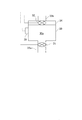
本実施形態に係る燃料残量計測装置20aは、図5に示すように、上記燃料残量計測装置20に対して、燃料タンク10よりも小さな容積であって燃料タンク10内および大気に連通可能な調整室30と、第1調整弁31および第2調整弁32の2つの調整弁とをさらに備えるように構成されている。
As shown in FIG. 5, the fuel remaining
第1調整弁31は、調整室30内と燃料タンク10内とを連通する配管33aに設けられており、制御回路23により制御されて調整室30内と燃料タンク10内との連通を制御する調整弁として機能する。第2調整弁32は、調整室30内と大気とを連通する配管33bに設けられており、制御回路23により制御されて調整室30内と大気との連通を制御する調整弁として機能する。このため、調整室30は、両調整弁31,32がともに閉弁状態となることで密閉状態に維持される。
The
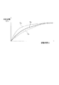
次に、調整室30等を圧力調整手段として利用した燃料残量の計測について、図6を用いて説明する。
大気圧よりも低い圧力に減圧された燃料タンク10に対して大気圧状態にて密閉された調整室30を連通することで、燃料タンク10内を一定量だけ増圧する調整を実施することができる。そして、図6に示すように、燃料タンク10内の内圧Pが大気圧よりも低く設定された開始圧力P1から目標圧力P2まで増圧するために上記調整工程を繰り返した時の調整回数Nは、内気体積V1が大きくなるほど多くなる。すなわち、内気体積V1に応じて、内圧Pを圧力変化させるために要する両調整弁31,32等の圧力調整手段の調整回数Nが変化する。
Next, measurement of the remaining amount of fuel using the
By connecting the
そこで、本実施形態では、制御回路23にて実施される燃料残量計測処理にて、内圧Pを開始圧力P1から目標圧力P2まで変化させるために要する調整回数Nをカウントし、この調整回数Nに応じて燃料タンク10内の内気体積V1を求める。なお、本実施形態では、例えば、目標圧力P2は、大気圧に等しくなるように設定され、開始圧力P1は、目標圧力P2よりも20kPa低い値に設定されている。
Therefore, in the present embodiment, the number N of adjustments required to change the internal pressure P from the start pressure P1 to the target pressure P2 is counted in the remaining fuel amount measurement process performed by the
以下、本実施形態において、制御回路23にて実施される燃料残量計測処理について、図7を用いて詳細に説明する。なお、燃料残量計測処理が開始された直後の初期設定として、調整回数Nが0に設定される。
Hereinafter, the remaining fuel amount measurement process performed by the
制御回路23による燃料残量計測処理が開始されると、まず、図7のステップS201に示す初期圧力調整処理がなされる。この処理では、センサ21にて検出される内圧Pが開始圧力P1になるように減圧ポンプ22が駆動される。
When the remaining fuel amount measurement process by the
次に、調整回数Nがインクリメント(N=N+1)されると(S203)、第2調整弁32のみが開弁状態になり(S205)、調整室30内の圧力が大気圧と等しくなる。続いて、第2調整弁32が閉弁状態になったあと(S207)、第1調整弁31のみが開弁状態になる(S209)。これにより、調整室30内と燃料タンク10内とが連通することで減圧された調整室30内の内気の圧力と等しくなるように燃料タンク10内の内圧Pが増加する。そして、第1調整弁31が閉弁状態になり(S211)、調整室30内と燃料タンク10内との連通が遮断される。なお、上記ステップS203を実施する制御回路23は、「計数手段」の一例に相当し得る。
Next, when the number of adjustments N is incremented (N = N + 1) (S203), only the
そして、調整回数Nが規定回数No未満であり(S213でNo)、燃料タンク10内の内圧Pが目標圧力P2に到達していなければ(S215でNo)、上記ステップS203からの処理が繰り返され、調整回数Nが1つ増えるとともに燃料タンク10内が一定量だけ増圧される圧力調整が繰り返される。
If the number of adjustments N is less than the prescribed number No (No in S213) and the internal pressure P in the
そして、上述のように繰り返される圧力調整により、燃料タンク10内の内圧Pが目標圧力P2に到達したとみなされると(S215でYes)、ステップS217に示す内気体積算出処理がなされる。この処理では、内圧Pが目標圧力P2に到達したとみなされたときの調整回数Nに基づいて内気体積V1が求められる。
具体的には、以下に示す式(1)により内気体積V1が算出される。
V1=P1×N×V3/(P2−P1) ・・・(1)
なお、V3は、両調整弁31,32により密閉された状態での調整室30の容積を示している。
When it is determined that the internal pressure P in the
Specifically, the inside air volume V1 is calculated by the following equation (1).
V1 = P1 * N * V3 / (P2-P1) (1)
V3 indicates the volume of the
上述のように内気体積V1が求められると、ステップS219に示す燃料残量演算処理がなされる。この処理では、燃料タンク10の全容積Vから内気体積V1を除くことで燃料が占める体積V2(=V−V1)が演算され、この演算結果に基づいて燃料残量が計測される。そして、計測された燃料残量に基づいて上記表示信号が生成されて表示機12に出力される(S221)。これにより、表示機12では、入力された表示信号に基づいて指針が回転し、燃料Fの燃料残量が視認者に報知される。
When the inside air volume V1 is obtained as described above, the remaining fuel amount calculation process shown in step S219 is performed. In this process, the volume V2 (= V−V1) occupied by the fuel is calculated by removing the inside air volume V1 from the total volume V of the
一方、内圧Pが目標圧力P2に到達する前に(S215でNo)、規定回数Nが規定回数Noに到達すると(S213でYes)、ステップS223に示すエラー報知処理がなされる。この処理では、上記第1実施形態と同様に、燃料残量の計測精度が低下していることを示す情報が、エラー情報として報知される。なお、上記規定回数Noは、燃料Fが入っていない状態での燃料タンク10の内圧Pが上記調整室30を利用した圧力調整により開始圧力P1から目標圧力P2に到達するまでにかかる調整回数よりも大きな値に設定されている。
On the other hand, before the internal pressure P reaches the target pressure P2 (No in S215), when the specified number N reaches the specified number No (Yes in S213), an error notification process shown in step S223 is performed. In this process, as in the first embodiment, information indicating that the measurement accuracy of the remaining amount of fuel is reduced is notified as error information. The specified number of times No is based on the number of adjustments required for the internal pressure P of the
以上説明したように、本実施形態に係る燃料残量計測装置20aでは、圧力調整手段として、調整室30および両調整弁31,32が設けられている。そして、大気圧よりも低い開始圧力P1に減圧された燃料タンク10に対して大気圧状態にて密閉された調整室30を連通することで燃料タンク10内を一定量だけ増圧する調整が繰り返される際に、内気Gの内圧Pを開始圧力P1から目標圧力P2まで変化させるために要する調整回数Nがカウントされる。そして、カウントされた調整回数Nに応じて燃料タンク10内にて内気Gが占める内気体積V1が求められる。
As described above, in the fuel remaining
このように、内気Gの内圧Pに関する調整度合いとして調整回数Nを採用することで、減圧ポンプ22を圧力調整手段として用いることなく燃料タンク10内の内気Gの内気体積V1を求めることができる。
Thus, by adopting the number N of adjustments as the degree of adjustment related to the internal pressure P of the internal air G, the internal air volume V1 of the internal air G in the
また、調整回数Nが規定回数Noを超えると、表示機12の警告灯12a等によりエラー情報が報知されるため、燃料残量の計測精度が低下していることを視認者に対して早期に知らせることができる。なお、第1調整弁31や第2調整弁32を開弁しても内圧Pが変化しないときにも、エラー情報等を報知してもよい。
Further, when the number of adjustments N exceeds the specified number of times, error information is notified by the warning
なお、本実施形態における燃料残量計測処理は、上記第1実施形態における燃料残量計測処理の後に実施することができる。すなわち、上記第1実施形態における燃料残量計測処理の後に燃料タンク10内の内圧Pが目標圧力P2となると、この目標圧力P2を上記第2実施形態における開始圧力P1として燃料残量計測処理を実施する。これにより、調整時間tに基づく燃料残量の計測と、調整回数Nに基づく燃料残量の計測との双方の計測結果を比較することで、燃料残量の計測精度をさらに向上させることができる。
Note that the remaining fuel amount measurement process in the present embodiment can be performed after the remaining fuel amount measurement process in the first embodiment. That is, when the internal pressure P in the
[第3実施形態]
次に、本発明の第3実施形態に係る燃料残量計測装置について、図8〜図10を用いて説明する。なお、図8は、第3実施形態に係る燃料残量計測装置20aの要部を示す説明図である。図9は、可動壁34が初期位置から燃料タンク10側に移動量Xだけ移動した状態を示す説明図である。図10は、第3実施形態において制御回路23にて実施される燃料残量計測処理の流れを例示するフローチャートである。
[Third Embodiment]
Next, a fuel remaining amount measuring apparatus according to a third embodiment of the present invention will be described with reference to FIGS. In addition, FIG. 8 is explanatory drawing which shows the principal part of the fuel residual
本第3実施形態では、圧力調整手段として、固定式の第2調整弁32に代えて第2調整弁32の機能を有する可動壁34を採用する点が主に上記第2実施形態と異なる。このため、第2実施形態と実質的に同様の構成部分には同一符号を付して説明を省略する。
The third embodiment is mainly different from the second embodiment in that a
本実施形態に係る燃料残量計測装置20aの調整室30には、図8に示すように、上述した第2調整弁32に代えて可動壁34が設けられている。可動壁34は、中央に上記第2調整弁32が設けられており、この第2調整弁32の開弁状態を除き調整室30内において配管33a側と配管33b側とを気密的に区画するように配置されている。
As shown in FIG. 8, a
この可動壁34は、配管33a側の圧力と配管33b側の圧力との圧力差に応じて調整室30内をその壁面に沿うように移動可能に支持されている。特に、可動壁34は、第2調整弁32が開弁状態であり上記圧力差が無い場合には、図略の付勢部材等により付勢されて図8に示す初期位置に移動する。
The
このため、第2調整弁32が閉弁状態では、可動壁34は、燃料タンク10内の内圧Pが大気圧よりも低い場合には、図9に示すように、上記初期位置から燃料タンク10側に移動し、この可動壁34の移動に応じて、調整室30内のうち可動壁34により区画される配管33a側の室(以下、燃料側区画室30aともいう)の容積(以下、区画室容積Vxともいう)が変化する。そして、可動壁34は、その移動の過程において燃料タンク10内の内圧Pが大気圧とほぼ等しくなると、上記圧力差がなくなるため、その位置で止まることとなる。
For this reason, when the
調整室30には、可動壁34の位置を検出する位置検出センサ35が設けられている。この位置検出センサ35は、可動壁34の移動量Xを検出可能な移動量検出手段として機能するもので、図9に示すように可動壁34が燃料タンク10側に移動量Xだけ移動している場合には、この移動量Xに対応する信号を制御回路23に出力するように構成されている。
The
次に、調整室30および可動壁34等を圧力調整手段として利用した燃料残量の計測について、以下に説明する。
上記第2実施形態における燃料残量の計測構成では、上記式(1)からわかるように、燃料タンク10内の内圧Pが目標圧力P2に到達したとみなされたとき、調整室30の容積V3の全ての内気を燃料タンク10内に連通したとして内気体積V1が求められる。そうすると、最後の圧力調整にて、例えば、調整室30の内気の一部を連通するだけで内圧Pが目標圧力P2に到達した場合と、調整室30の全ての内気を連通することで内圧Pが目標圧力P2に到達した場合とで、算出される内気体積V1が同じ値となる。このため、内気体積V1の算出精度が低下してしまい、その結果、燃料残量の測定精度が低下するという問題が生じる。
Next, the measurement of the remaining amount of fuel using the
In the measurement configuration of the remaining amount of fuel in the second embodiment, as can be seen from the above equation (1), when it is considered that the internal pressure P in the
この問題は、調整室30の容積が大きくなるほど顕著になる。一方、調整室30の容積を小さくすると上記問題が多少解消されるものの、調整回数Nが多くなることから内圧Pが目標圧力P2に到達するまでの時間が長くなり、燃料残量の計測に関する応答性が悪くなるという問題が生じる。
This problem becomes more prominent as the volume of the
そこで、本実施形態では、制御回路23にて実施される燃料残量計測処理にて、燃料タンク10内の内圧Pが目標圧力P2に到達したとみなされたときの可動壁34の位置に基づいて燃料側区画室30aの区画室容積Vxを算出し、この区画室容積Vxと調整回数Nに応じて燃料タンク10内の内気体積V1を求める。上記区画室容積Vxは、最後の圧力調整にて内圧Pを目標圧力P2に到達させるために必要な内気の体積に相当し、この区画室容積Vxを考慮することで内気体積V1の算出精度を向上させることができるからである。
Thus, in the present embodiment, based on the position of the
以下、本実施形態において、制御回路23にて実施される燃料残量計測処理について、図10を用いて詳細に説明する。
制御回路23による燃料残量計測処理が開始され、上記第2実施形態と同様に両調整弁31,32の開閉による圧力調整が繰り返される際、第2調整弁32のみが開弁状態になり(図10のS205)、調整室30内の圧力が大気圧と等しくなった後に、第2調整弁32が閉弁状態になった後(S207)、第1調整弁31のみが開弁状態になる(S209)。
Hereinafter, the remaining fuel amount measurement process performed by the
When the remaining fuel amount measurement process by the
これにより、燃料側区画室30aと燃料タンク10内とが連通することで減圧された燃料側区画室30a内の内気の圧力に応じて可動壁34が移動し、区画室容積Vxが小さくなるとともに燃料タンク10内の内圧Pが増加する。なお、燃料タンク10内の内圧Pが大気圧よりも十分に低い場合には、可動壁34は区画室容積Vxを最小とする限界位置まで移動する。そして、第1調整弁31が閉弁状態になると(S211)、上記圧力差がなくなることから、可動壁34が初期位置まで戻る(図8参照)。このような可動壁34の移動が燃料タンク10内の内圧Pが目標圧力P2に到達したとみなされるまで繰り返される。
As a result, the
そして、燃料タンク10内の内圧Pが目標圧力P2に到達したとみなされると(S215でYes)、ステップS216に示す区画室容積算出処理がなされる。この処理では、内圧Pが目標圧力P2に到達したとみなされたときに位置検出センサ35にて検出される可動壁34の位置に基づいて区画室容積Vxが求められる。
When it is considered that the internal pressure P in the
続いて、ステップS217aに示す内気体積算出処理がなされる。この処理では、内圧Pが目標圧力P2に到達したとみなされたときの調整回数Nと区画室容積Vxとに基づいて、以下に示す式(2)により内気体積V1が求められる。
V1=P1×(N×V3+Vx)/(P2−P1) ・・・(2)
Subsequently, an inside air volume calculation process shown in step S217a is performed. In this process, based on the number of adjustments N and the compartment volume Vx when the internal pressure P is considered to have reached the target pressure P2, the internal air volume V1 is obtained by the following equation (2).
V1 = P1 × (N × V3 + Vx) / (P2−P1) (2)
上述のように内気体積V1が求められると、ステップS219に示す燃料残量演算処理にて燃料が占める体積V2(=V−V1)が演算され、この演算結果に基づいて燃料残量が計測される。そして、計測された燃料残量に基づいて上記表示信号が生成されて表示機12に出力される(S221)。これにより、表示機12では、入力された表示信号に基づいて指針が回転し、燃料Fの燃料残量が視認者に報知される。
When the inside air volume V1 is obtained as described above, the volume V2 (= V−V1) occupied by the fuel is calculated in the remaining fuel amount calculation process shown in step S219, and the remaining fuel amount is measured based on the calculation result. The And the said display signal is produced | generated based on the measured fuel remaining amount, and it outputs to the indicator 12 (S221). Thereby, in the
以上説明したように、本実施形態に係る燃料残量計測装置20aでは、燃料タンク10内の内圧Pが目標圧力P2に到達したとみなされたときの可動壁34の移動量Xに基づいて、燃料側区画室30aの区画室容積Vxを算出し、この区画室容積Vxと調整回数Nに応じて燃料タンク10内の内気体積V1を求める。
As described above, in the fuel remaining
このように、最後の圧力調整にて内圧Pを目標圧力P2に到達させるために必要な内気の体積に相当する区画室容積Vxを考慮することで、内気体積V1の算出精度が向上するので、燃料残量の測定精度を向上させることができる。 Thus, the calculation accuracy of the internal air volume V1 is improved by taking into account the compartment volume Vx corresponding to the internal air volume necessary for the internal pressure P to reach the target pressure P2 in the final pressure adjustment. The measurement accuracy of the remaining amount of fuel can be improved.
なお、本発明は上記各実施形態に限定されるものではなく、例えば、以下のように具体化してもよい。
(1)上記燃料残量計測処理では、内気体積V1を、減圧ポンプ22により内圧Pを開始圧力P1から目標圧力P2まで減圧させるために要する調整時間tや調整室30等により内圧Pを開始圧力P1から目標圧力P2まで増圧させるために要する調整回数Nに応じて求めることに限らず、他の圧力調整手段により燃料タンク10内の圧力Pを開始圧力P1から目標圧力P2まで変化させるために要する調整度合いに応じて求めてもよい。
In addition, this invention is not limited to said each embodiment, For example, you may actualize as follows.
(1) In the fuel remaining amount measurement process, the internal pressure P is started by the adjustment time t required for reducing the internal pressure V1 from the start pressure P1 to the target pressure P2 by the
(2)燃料タンク10内の内圧Pおよび内気温度Tを検出する検出手段としてセンサ21を採用することに限らず、燃料タンク10内の内圧Pを検出する圧力センサ等の圧力検出手段と燃料タンク10内の内気温度Tを検出する温度センサ等の温度検出手段とをそれぞれ別途用意してもよい。
(2) The
10…燃料タンク
12…表示機12a…警告灯(報知手段)
20,20a…燃料残量計測装置
21…センサ(圧力検出手段,温度検出手段)
22…減圧ポンプ(圧力調整手段)
23…制御回路(圧力制御手段,計測手段,計時手段)
30…調整室(圧力調整手段)
31…第1調整弁(圧力調整手段)
32…第2調整弁(圧力調整手段)
34…可動壁
35…位置検出センサ(移動量検出手段)
DESCRIPTION OF
20, 20a ... Fuel remaining
22 ... Pressure reducing pump (pressure adjusting means)
23 ... Control circuit (pressure control means, measuring means, timing means)
30 ... Adjusting chamber (pressure adjusting means)
31. First adjusting valve (pressure adjusting means)
32. Second adjusting valve (pressure adjusting means)
34 ...
Claims (8)
前記燃料タンク内の内気(G)の圧力(P)を検出する圧力検出手段(21)と、
前記内気の圧力(P)を調整する圧力調整手段(22,30〜32,34)と、
前記圧力調整手段を制御する圧力制御手段(23)と、
前記燃料残量を計測する計測手段(23)と、
を備え、
前記計測手段は、前記圧力制御手段にて制御される前記圧力調整手段により前記内気の圧力を予め決められた開始圧力(P1)から目標圧力(P2)まで変化させるために要する調整度合い(t,N)に応じて前記燃料タンク内にて前記内気が占める体積(V1)を求め、前記内気の体積から演算される前記燃料タンク内にて前記燃料が占める体積(V2)に基づいて前記燃料残量を計測することを特徴とする燃料残量計測装置。 A fuel remaining amount measuring device (20, 20a) for measuring a fuel remaining amount in a fuel tank (10) in which fuel (F) is stored,
Pressure detecting means (21) for detecting the pressure (P) of the inside air (G) in the fuel tank;
Pressure adjusting means (22, 30 to 32, 34) for adjusting the pressure (P) of the inside air;
Pressure control means (23) for controlling the pressure adjusting means;
Measuring means (23) for measuring the fuel remaining amount;
With
The measuring means is an adjustment degree (t, t) required for changing the pressure of the inside air from a predetermined start pressure (P1) to a target pressure (P2) by the pressure adjusting means controlled by the pressure control means. N), the volume (V1) occupied by the inside air in the fuel tank is obtained, and the fuel remaining amount is calculated based on the volume (V2) occupied by the fuel in the fuel tank calculated from the volume of the inside air. A fuel remaining amount measuring device characterized by measuring the amount.
前記計測手段は、前記計時手段により計時された調整時間に応じて前記内気の体積を求めることを特徴とする請求項1に記載の燃料残量計測装置。 A time measuring means (23) for measuring an adjustment time (t) required for changing the pressure of the inside air from the start pressure to the target pressure by the pressure adjusting means;
2. The fuel remaining amount measuring apparatus according to claim 1, wherein the measuring unit obtains the volume of the inside air in accordance with an adjustment time measured by the time measuring unit.
前記マップは、前記内気の温度に応じて前記調整時間と前記内気の体積との関係が複数種類設定され、
前記計測手段は、前記温度検出手段により検出された前記内気の温度と前記計時手段により計時された調整時間とに応じて前記マップから前記内気の体積を求めることを特徴とする請求項3に記載の燃料残量計測装置。 Temperature detecting means (21) for detecting the temperature (T) of the inside air,
In the map, a plurality of types of relationships between the adjustment time and the volume of the inside air are set according to the temperature of the inside air,
The said measurement means calculates | requires the volume of the said inside air from the said map according to the temperature of the said inside air detected by the said temperature detection means, and the adjustment time timed by the said time measuring means. Fuel level measuring device.
前記圧力調整手段は、前記燃料タンクよりも小さな容積(V3)であって前記燃料タンク内および大気に連通可能な調整室(30)を有し、
前記計数手段は、前記圧力制御手段にて制御される前記圧力調整手段により、大気圧よりも低い圧力に減圧された前記燃料タンクに対して大気圧状態にて密閉された前記調整室を連通することで前記燃料タンク内を増圧する調整が繰り返される際に、前記内気の圧力を前記開始圧力から前記目標圧力まで変化させるために要する回数を前記調整回数としてカウントし、
前記計測手段は、前記計数手段によりカウントされた調整回数に応じて前記内気の体積を求めることを特徴とする請求項1に記載の燃料残量計測装置。 A counting means (23) for counting the number of adjustments (N) by the pressure adjusting means;
The pressure adjusting means has a regulating chamber (30) having a smaller volume (V3) than the fuel tank and capable of communicating with the inside of the fuel tank and the atmosphere,
The counting means communicates the adjustment chamber sealed in an atmospheric pressure state with the fuel tank whose pressure is reduced to a pressure lower than the atmospheric pressure by the pressure adjusting means controlled by the pressure control means. When the adjustment for increasing the pressure in the fuel tank is repeated, the number of times required to change the inside air pressure from the start pressure to the target pressure is counted as the number of adjustments,
2. The fuel remaining amount measuring apparatus according to claim 1, wherein the measuring unit obtains the volume of the inside air in accordance with the number of adjustments counted by the counting unit.
前記調整室内に配置されて前記内圧と大気圧との圧力差に応じて当該調整室内を移動可能な可動壁(34)と、
前記可動壁の移動量(X)を検出可能な移動量検出手段(35)と、を備え、
前記計測手段は、前記移動量検出手段により検出された前記可動壁の移動量と前記計数手段によりカウントされた調整回数とに応じて前記内気の体積を求めることを特徴とする請求項6に記載の燃料残量計測装置。 The pressure adjusting means is
A movable wall (34) disposed in the adjustment chamber and movable in the adjustment chamber according to a pressure difference between the internal pressure and the atmospheric pressure;
A movement amount detection means (35) capable of detecting the movement amount (X) of the movable wall;
The said measurement means calculates | requires the volume of the said inside air according to the movement amount of the said movable wall detected by the said movement amount detection means, and the frequency | count of adjustment counted by the said counting means. Fuel level measuring device.
Priority Applications (1)
| Application Number | Priority Date | Filing Date | Title |
|---|---|---|---|
| JP2013257754A JP2015114252A (en) | 2013-12-13 | 2013-12-13 | Fuel level measuring device |
Applications Claiming Priority (1)
| Application Number | Priority Date | Filing Date | Title |
|---|---|---|---|
| JP2013257754A JP2015114252A (en) | 2013-12-13 | 2013-12-13 | Fuel level measuring device |
Publications (1)
| Publication Number | Publication Date |
|---|---|
| JP2015114252A true JP2015114252A (en) | 2015-06-22 |
Family
ID=53528170
Family Applications (1)
| Application Number | Title | Priority Date | Filing Date |
|---|---|---|---|
| JP2013257754A Pending JP2015114252A (en) | 2013-12-13 | 2013-12-13 | Fuel level measuring device |
Country Status (1)
| Country | Link |
|---|---|
| JP (1) | JP2015114252A (en) |
Cited By (1)
| Publication number | Priority date | Publication date | Assignee | Title |
|---|---|---|---|---|
| JP2021067686A (en) * | 2019-10-18 | 2021-04-30 | エフ.ホフマン−ラ ロシュ アーゲーF. Hoffmann−La Roche Aktiengesellschaft | Techniques for checking state of analyzer |
-
2013
- 2013-12-13 JP JP2013257754A patent/JP2015114252A/en active Pending
Cited By (2)
| Publication number | Priority date | Publication date | Assignee | Title |
|---|---|---|---|---|
| JP2021067686A (en) * | 2019-10-18 | 2021-04-30 | エフ.ホフマン−ラ ロシュ アーゲーF. Hoffmann−La Roche Aktiengesellschaft | Techniques for checking state of analyzer |
| US11530943B2 (en) | 2019-10-18 | 2022-12-20 | Roche Diagnostics Operations, Inc. | Techniques for checking state of analyzers |
Similar Documents
| Publication | Publication Date | Title |
|---|---|---|
| US9758097B2 (en) | Remaining fuel amount display device | |
| JP4816102B2 (en) | Tire pressure monitoring system | |
| JP4333467B2 (en) | Tire pressure detector | |
| CN101460322B (en) | Tire risk judging device of wheel assembly for vehicle | |
| CN108344463A (en) | Control method, control system and the vehicle of fuel gauge of vehicle | |
| KR102021402B1 (en) | Method for correcting a state of charge of a state of charge display | |
| JP2015130339A (en) | Apparatus and method for controlling purging in hydrogen storage system | |
| JP2005091341A (en) | Vehicle travelable distance display device and method | |
| KR20160049472A (en) | Remaining fuel level displaying method for fuel cell system and fuel cell equipped vehicle | |
| JP2015114252A (en) | Fuel level measuring device | |
| JP2022165827A (en) | tire pressure monitoring system | |
| JP5026427B2 (en) | Method and apparatus for detecting leaks in an automotive air spring assembly | |
| US20150377686A1 (en) | Fuel tank having an activated carbon filter and method to display the fuel level of the fuel tank with signal supression at a critical negative pressure during regeneration of the activated carbon filter | |
| US20220234397A1 (en) | System and method for tire leak detection | |
| JP4106634B2 (en) | Fuel remaining amount display device and display method thereof | |
| CN102639364B (en) | Vehicle display device | |
| CN110614918B (en) | Method for judging slope parking and refueling of automobile fuel system | |
| JP2003028393A (en) | Gas fuel storage device for gas fuel vehicle | |
| JP4822106B2 (en) | Flow rate measuring device and accuracy check method thereof | |
| US20050062593A1 (en) | Customizable low fuel indicator system | |
| JP2015132241A (en) | Control device for internal combustion engine | |
| JP2017110514A (en) | Fuel tank system | |
| CN205503222U (en) | Machine oil filling suggestion device | |
| CN212720387U (en) | Calibration device for refrigerant charge | |
| KR102506875B1 (en) | Tire pressure monitoring apparatus and method |