JP2015114203A - Annulus air purification system and nuclear power plant - Google Patents
Annulus air purification system and nuclear power plant Download PDFInfo
- Publication number
- JP2015114203A JP2015114203A JP2013256392A JP2013256392A JP2015114203A JP 2015114203 A JP2015114203 A JP 2015114203A JP 2013256392 A JP2013256392 A JP 2013256392A JP 2013256392 A JP2013256392 A JP 2013256392A JP 2015114203 A JP2015114203 A JP 2015114203A
- Authority
- JP
- Japan
- Prior art keywords
- annulus
- steam
- air
- driven
- air purification
- Prior art date
- Legal status (The legal status is an assumption and is not a legal conclusion. Google has not performed a legal analysis and makes no representation as to the accuracy of the status listed.)
- Pending
Links
Images
Classifications
-
- Y—GENERAL TAGGING OF NEW TECHNOLOGICAL DEVELOPMENTS; GENERAL TAGGING OF CROSS-SECTIONAL TECHNOLOGIES SPANNING OVER SEVERAL SECTIONS OF THE IPC; TECHNICAL SUBJECTS COVERED BY FORMER USPC CROSS-REFERENCE ART COLLECTIONS [XRACs] AND DIGESTS
- Y02—TECHNOLOGIES OR APPLICATIONS FOR MITIGATION OR ADAPTATION AGAINST CLIMATE CHANGE
- Y02E—REDUCTION OF GREENHOUSE GAS [GHG] EMISSIONS, RELATED TO ENERGY GENERATION, TRANSMISSION OR DISTRIBUTION
- Y02E30/00—Energy generation of nuclear origin
- Y02E30/30—Nuclear fission reactors
Landscapes
- Structure Of Emergency Protection For Nuclear Reactors (AREA)
Abstract
Description
本発明は、原子炉格納容器の外側に設けられるアニュラス内の空気を浄化処理するアニュラス空気浄化装置及び全ての交流電源が喪失したときに、原子炉の安定を維持させるための機能を有する原子力発電プラントに関するものである。 The present invention relates to an annulus air purification device for purifying air in an annulus provided outside a reactor containment vessel and a nuclear power generation having a function for maintaining the stability of a nuclear reactor when all AC power is lost. It relates to the plant.
例えば、加圧水型原子炉(PWR:Pressurized Water Reactor)を有する原子力発電プラントは、軽水を原子炉冷却材及び中性子減速材として使用し、原子炉の炉心全体にわたって沸騰しない高温高圧水とし、この高温高圧水を蒸気発生器に送って熱交換により蒸気を発生させ、この蒸気をタービン発電機へ送って発電するものである。そして、蒸気発生器は、原子炉からの高温高圧の一次冷却材の熱を二次冷却材に伝え、二次冷却材で水蒸気を発生させるものである。 For example, a nuclear power plant having a pressurized water reactor (PWR) uses light water as a reactor coolant and a neutron moderator to produce high-temperature and high-pressure water that does not boil throughout the reactor core. Water is sent to a steam generator to generate steam by heat exchange, and this steam is sent to a turbine generator to generate electricity. And a steam generator transmits the heat | fever of the high temperature / high pressure primary coolant from a nuclear reactor to a secondary coolant, and produces | generates water vapor | steam with a secondary coolant.
このような原子力発電プラントにて、原子炉格納容器は、内部に加圧水型原子炉、蒸気発生器、加圧器、冷却水ポンプなどが収容されている。また、原子炉格納容器は、外側に遮へい壁などの壁部が設けられ、原子炉格納容器と壁部との間にアニュラスが設けられている。このアニュラスは、原子炉格納容器と壁部の間の形成された空間であり、圧力境界である一次冷却系配管などが破損したり、弁が開いたままになって一次冷却材が流出し続け、通常の給水系では原子炉内の一次冷却材の量を維持できない事態、一次冷却材喪失事故(LOCA:Loss-of-coolant Accident)等が発生したときに、原子炉格納容器内の圧力上昇によって、原子炉格納容器の貫通部などから漏洩した放射性物質を含むガスの閉じ込めを可能とする。この放射性物質を含むアニュラス内の汚染された雰囲気を、アニュラス空気浄化装置は、アニュラス内の圧力を大気圧以下に維持することで外部への漏洩を抑制可能とすると共に、浄化処理可能としている。 In such a nuclear power plant, the reactor containment vessel contains therein a pressurized water reactor, a steam generator, a pressurizer, a cooling water pump, and the like. Further, the reactor containment vessel is provided with a wall portion such as a shielding wall on the outside, and an annulus is provided between the reactor containment vessel and the wall portion. This annulus is a space formed between the reactor containment vessel and the wall, and the primary cooling system piping that is the pressure boundary is damaged, or the valve remains open and the primary coolant continues to flow out. When the normal coolant supply system cannot maintain the amount of primary coolant in the reactor, the loss of primary coolant (LOCA: Loss-of-coolant Accident) occurs, etc. This makes it possible to confine the gas containing radioactive material leaked from the penetration portion of the reactor containment vessel. The annulus air purifying apparatus maintains the pressure inside the annulus at atmospheric pressure or lower, and can suppress the leakage to the outside and the purification process.
このような原子力発電プラントとしては、例えば、下記特許文献1に記載されたものがある。 An example of such a nuclear power plant is described in Patent Document 1 below.
上述した通り、原子力発電プラントにて、LOCAが発生したときに、アニュラス空気浄化装置を作動することで、アニュラス内の圧力を大気圧以下(負圧)に維持することで外部への漏洩を抑制すると共に、アニュラス内の雰囲気を浄化している。但し、アニュラス空気浄化装置は、交流電源設備により作動するものであるが、全ての交流電源設備が喪失した場合も想定した、更なる安全性の向上が期待されている。 As described above, when LOCA occurs in a nuclear power plant, operating the annulus air purification device suppresses leakage to the outside by maintaining the pressure inside the annulus below atmospheric pressure (negative pressure). At the same time, the atmosphere in the annulus is purified. However, although the annulus air purification device is operated by an AC power supply facility, further improvement in safety is expected assuming that all AC power supply facilities are lost.
本発明は、上述した課題を解決するものであり、原子炉における安全性の向上を可能とするアニュラス空気浄化装置及び原子力発電プラントを提供することを目的とする。 The present invention solves the above-described problems, and an object thereof is to provide an annulus air purification apparatus and a nuclear power plant that can improve safety in a nuclear reactor.
上記の目的を達成するための本発明のアニュラス空気浄化装置は、原子炉格納容器と外側に設置される壁部との間にアニュラスが設けられ、前記アニュラス内雰囲気の負圧維持及び浄化をするアニュラス空気浄化装置において、端部が前記アニュラスに連結される大気放出ラインと、前記大気放出ラインに設けられる電動式空気排出装置と、前記大気放出ラインに設けられる空気浄化フィルタと、前記大気放出ラインに前記電動式空気排出装置を迂回するように設けられる蒸気駆動式空気排出装置と、を有することを特徴とするものである。 In order to achieve the above object, an annulus air purification apparatus of the present invention is provided with an annulus between a reactor containment vessel and a wall portion installed on the outside, and maintains and purifies the negative pressure in the atmosphere inside the annulus. In the annulus air purification device, an atmospheric discharge line whose end is connected to the annulus, an electric air discharge device provided in the atmospheric discharge line, an air purification filter provided in the atmospheric discharge line, and the atmospheric discharge line And a steam-driven air discharge device provided so as to bypass the electric air discharge device.
従って、アニュラスに連結される大気放出ラインに電動式空気排出装置と空気浄化フィルタを設けると共に、電動式空気排出装置を迂回する蒸気駆動式空気排出装置を設けることで、例えば、全ての電源喪失時に、電動式空気排出装置に代えて蒸気駆動式空気排出装置が作動するため、アニュラス内の雰囲気を空気浄化フィルタにより浄化してから排出することができ、原子炉における安全性を向上することができる。 Therefore, by providing an electric air exhaust device and an air purification filter in the atmospheric discharge line connected to the annulus, and providing a steam-driven air exhaust device that bypasses the electric air exhaust device, for example, when all power is lost Since the steam-driven air exhaust device operates instead of the electric air exhaust device, the atmosphere in the annulus can be exhausted after being purified by the air purification filter, and the safety in the nuclear reactor can be improved. .
本発明のアニュラス空気浄化装置では、前記蒸気駆動式空気排出装置は、蒸気発生器によって二次冷却材を蒸発させた二次系水蒸気により駆動することを特徴としている。 In the annulus air purification device of the present invention, the steam-driven air discharge device is driven by secondary steam obtained by evaporating the secondary coolant by a steam generator.
従って、蒸気駆動式空気排出装置を駆動するための蒸気として原子炉の二次系蒸気を使用するため、身近にある安全な蒸気を使用して蒸気駆動式空気排出装置を駆動することとなり、アニュラス空気浄化装置を作動することができる。 Therefore, since the secondary steam of the reactor is used as the steam for driving the steam-driven air exhaust device, the steam-driven air exhaust device is driven using safe nearby steam. The air purification device can be activated.
本発明のアニュラス空気浄化装置では、前記蒸気駆動式空気排出装置は、ファンを有することを特徴としている。 In the annulus air purification device of the present invention, the steam-driven air discharge device has a fan.
従って、蒸気駆動式空気排出装置をファンとすることで、アニュラス内の雰囲気を空気浄化フィルタにより浄化してから排出することができると共に、アニュラス内を負圧に維持することでアニュラス内の雰囲の外部漏洩を抑制することができる。 Therefore, by using the steam-driven air exhaust device as a fan, the atmosphere in the annulus can be exhausted after being purified by an air purification filter, and the atmosphere in the annulus can be maintained by maintaining a negative pressure in the annulus. External leakage can be suppressed.
本発明のアニュラス空気浄化装置では、前記蒸気駆動式空気排出装置は、エジェクタを有することを特徴としている。 In the annulus air purification device of the present invention, the steam-driven air discharge device has an ejector.
従って、蒸気駆動式空気排出装置をエジェクタとすることで、雰囲気を空気浄化フィルタにより浄化してから排出することができると共に、アニュラス内を負圧に維持することでアニュラス内の雰囲の外部漏洩を抑制することができる。 Therefore, by using a steam-driven air discharge device as an ejector, the atmosphere can be discharged after being purified by an air purification filter, and by maintaining the negative pressure inside the annulus, external leakage of the atmosphere in the annulus Can be suppressed.
本発明のアニュラス空気浄化装置では、前記アニュラスに冷却装置が設けられることを特徴としている。 In the annulus air purifying device of the present invention, the annulus is provided with a cooling device.
従って、例えば、全ての電源喪失時に、アニュラス内の雰囲気を冷却装置により冷却することで、このアニュラス内雰囲気の水蒸気が凝縮するため、アニュラス内を負圧に維持することができるので、アニュラス内雰囲気の外部漏洩を抑制することができる。 Therefore, for example, when all the power is lost, the atmosphere in the annulus is cooled by the cooling device, so that the water vapor in the annulus is condensed, so that the inside of the annulus can be maintained at a negative pressure. External leakage can be suppressed.
また、本発明の原子力発電プラントは、内部に原子炉及び蒸気発生器を格納する原子炉格納容器と、前記原子炉格納容器と外側に設置される壁部との間に設けられるアニュラスと、前記アニュラス内雰囲気の負圧維持及び浄化をする前記アニュラス空気浄化装置と、前記蒸気発生器で生成した二次系蒸気を前記蒸気駆動式空気排出装置に供給可能な蒸気供給ラインと、を有することを特徴とするものである。 Further, the nuclear power plant of the present invention includes a nuclear reactor containment vessel for storing a nuclear reactor and a steam generator therein, an annulus provided between the nuclear reactor containment vessel and a wall portion installed on the outside, The annulus air purification device for maintaining and purifying the negative pressure of the atmosphere inside the annulus, and a steam supply line capable of supplying secondary steam generated by the steam generator to the steam-driven air discharge device. It is a feature.
従って、蒸気供給ラインにより蒸気発生器で生成した二次系蒸気を蒸気駆動式空気排出装置に供給可能であることから、例えば、全ての電源喪失時に、電動式空気排出装置に代えて蒸気駆動式空気排出装置を作動することができ、アニュラス内の雰囲気を空気浄化フィルタにより浄化してから排出することができ、原子炉における安全性を向上することができる。 Therefore, since the secondary system steam generated by the steam generator can be supplied to the steam-driven air discharge device by the steam supply line, for example, when all the power is lost, the steam-driven type is used instead of the electric air discharge device. The air exhaust device can be operated, the atmosphere in the annulus can be exhausted after being purified by the air purification filter, and the safety in the nuclear reactor can be improved.
本発明の原子力発電プラントでは、前記全ての電源喪失時に蒸気供給ラインを開放可能な開閉弁が設けられることを特徴としている。 The nuclear power plant according to the present invention is characterized in that an on-off valve capable of opening the steam supply line when all the power sources are lost is provided.
従って、全ての電源喪失時に、開閉弁により蒸気供給ラインを開放することで、適正に二次系蒸気を蒸気駆動式空気排出装置に供給することができ、必要時に適正に蒸気駆動式空気排出装置を作動することができる。 Therefore, when all power is lost, the steam supply line is opened by the on-off valve, so that the secondary system steam can be properly supplied to the steam-driven air exhaust device. Can be activated.
本発明のアニュラス空気浄化装置及び原子力発電プラントによれば、大気放出ラインに電動式空気排出装置を迂回するように蒸気駆動式空気排出装置を設けるので、例えば、全ての電源喪失時に、電動式空気排出装置に代えて蒸気駆動式空気排出装置を作動することができ、アニュラス内の雰囲気を空気浄化フィルタにより浄化してから排出することができ、原子炉における安全性を向上することができる。 According to the annulus air purification device and the nuclear power plant of the present invention, the steam-driven air discharge device is provided in the atmospheric discharge line so as to bypass the electric air discharge device. A steam-driven air discharge device can be operated instead of the discharge device, and the atmosphere in the annulus can be discharged after being purified by the air purification filter, thereby improving the safety in the nuclear reactor.
以下に添付図面を参照して、本発明のアニュラス空気浄化装置及び原子力発電プラントの好適な実施形態を詳細に説明する。なお、この実施形態により本発明が限定されるものではなく、また、実施形態が複数ある場合には、各実施形態を組み合わせて構成するものも含むものである。 Exemplary embodiments of an annulus air purification device and a nuclear power plant according to the present invention will be described below in detail with reference to the accompanying drawings. In addition, this invention is not limited by this embodiment, and when there are two or more embodiments, what comprises combining each embodiment is also included.
[第1実施形態]
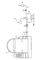
図1は、第1実施形態の原子力発電プラントにおけるアニュラス空気浄化装置を表す概略図、図2は、第1実施形態の原子力発電プラントを表す概略構成図である。
[First Embodiment]
FIG. 1 is a schematic diagram showing an annulus air purification device in the nuclear power plant of the first embodiment, and FIG. 2 is a schematic configuration diagram showing the nuclear power plant of the first embodiment.
第1実施形態の原子炉は、軽水を原子炉冷却材及び中性子減速材として使用し、炉心全体にわたって沸騰しない高温高圧水とし、この高温高圧水を蒸気発生器に送って熱交換により蒸気を発生させ、この蒸気をタービン発電機へ送って発電する加圧水型原子炉(PWR:Pressurized Water Reactor)である。 The nuclear reactor according to the first embodiment uses light water as a reactor coolant and a neutron moderator, and generates high-temperature and high-pressure water that does not boil over the entire core, and generates steam by heat exchange by sending this high-temperature and high-pressure water to a steam generator. And a pressurized water reactor (PWR) that generates power by sending the steam to a turbine generator.
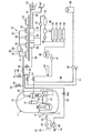
第1実施形態の加圧水型原子炉を有する原子力発電プラントにおいて、図2に示すように、原子炉格納容器11は、内部に加圧水型原子炉12及び蒸気発生器13が格納されており、この加圧水型原子炉12と蒸気発生器13とは配管14,15を介して連結されており、配管14に加圧器16が設けられ、配管15に一次冷却水ポンプ17が設けられている。この場合、減速材及び一次冷却水(冷却材)として軽水を用い、炉心部における一次冷却水の沸騰を抑制するために、一次冷却系統は加圧器16により高圧状態を維持するように制御している。従って、加圧水型原子炉12にて、燃料(原子燃料)により一次冷却水として軽水が加熱され、高温の一次冷却水が加圧器16により所定の高圧に維持した状態で配管14を通して蒸気発生器13に送られる。この蒸気発生器13では、高温高圧の一次冷却水と二次冷却水との間で熱交換が行われ、冷やされた一次冷却水は配管15を通して加圧水型原子炉12に戻される。
In the nuclear power plant having the pressurized water reactor according to the first embodiment, as shown in FIG. 2, the
蒸気発生器13は、配管18を介して蒸気タービン19と連結されており、この配管18に主蒸気隔離弁20が設けられている。蒸気タービン19は、高圧タービン21と低圧タービン22を有すると共に、発電機(発電装置)23が接続されている。また、高圧タービン21と低圧タービン22との間には、湿分分離加熱器24が設けられており、配管18から分岐した冷却水分岐配管25が湿分分離加熱器24に連結される一方、高圧タービン21と湿分分離加熱器24は低温再熱管26により連結され、湿分分離加熱器24と低圧タービン22は高温再熱管27により連結されている。
The
更に、蒸気タービン19の低圧タービン22は、復水器28を有しており、この復水器28は、配管18からバイパス弁29を有するタービンバイパス配管30が接続されると共に、冷却水(例えば、海水)を給排する取水管31及び排水管32が連結されている。この取水管31は、循環水ポンプ33を有し、排水管32と共に他端部が熱溜まり(例えば、海)に配置されている。
Further, the
そして、この復水器28は、配管34が接続されており、復水ポンプ35、グランドコンデンサ36、復水脱塩装置37、復水ブースタポンプ38、低圧給水加熱器39が接続されている。また、配管34は、脱気器40が連結されると共に、主給水ポンプ41、高圧給水加熱器42、主給水制御弁43などが設けられている。
The
また、配管18は、主蒸気逃がし弁44を有する主蒸気逃がし配管45の一端部と、主蒸気安全弁46を有する主蒸気安全配管47の一端部が接続されており、各配管45,47の他端部は大気に開放している。一方、配管34は、主給水制御弁43と蒸気発生器13との間に補助給水配管48の一端部が接続されており、この補助給水配管48は、補助給水ポンプ49が設けられると共に、他端部に復水タンク50が接続されている。この補助給水ポンプ49は、蒸気によりタービンが回転することで駆動するものであり、配管18における主蒸気安全配管47と主蒸気隔離弁20との間から分岐した駆動蒸気管51が補助給水ポンプ49まで延設されており、この駆動蒸気管51に開閉弁51aが設けられている。なお、蒸気により駆動する補助給水ポンプ49の他に、電動ポンプを適用してもよい。
The
従って、蒸気発生器13にて、高温高圧の一次冷却水と熱交換を行って生成された蒸気は、配管18を通して蒸気タービン19(高圧タービン21から低圧タービン22)に送られ、この蒸気により蒸気タービン19を駆動して発電機23により発電を行う。このとき、蒸気発生器13からの蒸気は、高圧タービン21を駆動した後、湿分分離加熱器24で蒸気に含まれる湿分が除去されると共に加熱されてから低圧タービン22を駆動する。そして、蒸気タービン19を駆動した蒸気は、復水器28で海水を用いて冷却されて復水となり、復水ポンプ35、グランドコンデンサ36、復水脱塩装置37、復水ブースタポンプ38、低圧給水加熱器39、脱気器40、主給水ポンプ41、高圧給水加熱器42などを通して蒸気発生器13に戻される。
Accordingly, the steam generated by exchanging heat with the high-temperature and high-pressure primary cooling water in the
この各種ポンプ17,33,35,38,41などは、常用電源装置(プラント内交流電源、外部電源、いずれも図示略)からの給電により駆動するものであることから、この電源装置の機能が喪失したときには、これらを駆動して冷却水を循環することができず、加圧水型原子炉12や蒸気発生器13を冷却することが困難となる。
The various pumps 17, 33, 35, 38, 41, and the like are driven by power supplied from a regular power supply device (in-plant AC power supply and external power supply, both not shown). When lost, these cannot be driven to circulate the cooling water, and it becomes difficult to cool the
そのため、常用電源装置が喪失したときには、非常用ディーゼル発電機を起動して、電動補助給水ポンプを駆動し、復水タンク50の復水を補助給水配管48から配管34を通して蒸気発生器13に供給し、主蒸気逃がし弁44の開放などで、蒸気発生器13の蒸気(二次冷却水)を配管18から主蒸気逃がし配管45や主蒸気安全配管47を通して大気に開放し、蒸気発生器13内の圧力を低下させて冷却している。また、非常用ディーゼル発電機が機能喪失した場合には、非常用バッテリによって開閉弁51aが開放し、配管18内の蒸気を駆動蒸気管51から補助給水ポンプ49に供給することで、蒸気によりこの補助給水ポンプ49を駆動し、復水タンク50の復水を補助給水配管48から配管34を通して蒸気発生器13に供給し、この蒸気発生器13を冷却している。そして、この間に電源装置の復旧を行っている。
Therefore, when the regular power supply is lost, the emergency diesel generator is activated, the electric auxiliary water supply pump is driven, and the condensate in the
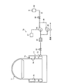
また、図1及び図2に示すように、原子炉格納容器11は、外側に壁部としての外部遮へい壁(または、原子炉建屋の壁)71が構築されることでアニュラス72が設けられている。このアニュラス72は、原子炉格納容器11と外部遮へい壁71の間の形成された空間であり、アニュラスシール73により密閉空間となっている。アニュラス72は、原子炉格納容器11に形成された出入口部74やエアロック75または各種配管(図示略)などの貫通部から漏洩した空気を浄化するものであり、アニュラス空気浄化装置76が接続されている。なお、アニュラス空気浄化装置(アニュラス空気浄化ライン)76は、高い安全性を確保する目的から複数設けられているが、ここでは省略している。
Further, as shown in FIGS. 1 and 2, the
アニュラス空気浄化装置76において、大気放出ライン81は、一端部がアニュラス72に連結され、他端部が排気塔82を介して大気に開放している。この大気放出ライン81は、アニュラス72と排気塔82との間に、アニュラス72側から排気弁83、空気浄化フィルタユニット84、電動式空気排出ファン(電動式空気排出装置)85、放出弁86が設けられている。
In the annulus
排気弁83及び放出弁86は、遠隔操作可能なフェイルオープン式の空気作動弁であって、放出弁86は、並列に配置される図示しない全量放出弁と少量放出弁とから構成されている。空気浄化フィルタユニット84は、粒子用フィルタ、ヨウ素用フィルタなどが直列に積層されて構成されている。電動式空気排出ファン85は、電源装置(プラント内交流電源、外部電源、非常用ディーゼル発電機、いずれも図示略)87が接続されている。
The
また、アニュラス空気浄化装置76は、大気放出ライン81に電動式空気排出ファン85を迂回するように迂回ライン88が設けられており、この迂回ライン88に蒸気駆動式空気排出装置89が設けられている。この蒸気駆動式空気排出装置89は、ファン(図示略)を有しており、原子力発電プラントの二次系蒸気により駆動することができる。即ち、一端部が配管18に接続された蒸気分岐配管90は、蒸気駆動式空気排出装置89まで延出され、蒸気分岐配管90に開閉弁90aが設けられている。
The annulus
このアニュラス空気浄化装置76は、冷却材喪失事故(LOCA)等が発生したとき、非常用炉心冷却設備の作動信号により電動式空気排出ファン85が自動起動し、アニュラス72内の雰囲気を空気浄化フィルタユニット84により浄化し、浄化後の空気を排気塔82から大気へ放出するものであり、アニュラス72は、事故発生後から予め設定された所定時間内に内部の負圧が達成される。
In this annulus
ところが、電動式空気排出ファン85は、電源装置87からの給電により駆動するものであることから、電源装置87が喪失したときには、この電動式空気排出ファン85を駆動してアニュラス72内の雰囲気を排出浄化して内部を負圧にすることができず、原子炉格納容器11からアニュアス72内へ漏洩した放射性物質を閉じ込めることが困難となる。
However, since the electric
そのため、電源装置87が喪失したとき、非常用バッテリまたは他の手段(例えば、手動操作)によって開閉弁90aを開放し、配管18内の蒸気を蒸気分岐配管90により蒸気駆動式空気排出装置89に供給することで、蒸気によりこの蒸気駆動式空気排出装置89を駆動し、アニュラス72内の雰囲気を空気浄化フィルタユニット84により浄化し、浄化後の空気を排気塔82から大気へ放出し、アニュラス72内の負圧を達成するようにしている。そして、この間に電源装置87の復旧を行っている。
Therefore, when the
ここで、第1実施形態の原子力発電プラントにおける作用について説明する。 Here, the effect | action in the nuclear power plant of 1st Embodiment is demonstrated.
第1実施形態の原子力発電プラントにおいて、図2に示すように、冷却材喪失事故(LOCA)等が発生し、更に、全ての電源装置87が喪失したとき、非常用バッテリまたは他の手段(例えば、手動操作)によって開閉弁90aを開放し、配管18内の蒸気を冷却水分岐配管51から冷却水分岐配管90により蒸気駆動式空気排出装置89に供給することで、蒸気によりこの蒸気駆動式空気排出装置89を駆動する。このとき、図1に示すように、例えば、代替空気源(例えば、ボンベ)によって排気弁83及び放出弁86の開放により、アニュラス72内の雰囲気を空気浄化フィルタユニット84により浄化し、浄化後の空気を排気塔82から大気へ放出する。そのため、原子炉格納容器11内に漏れた一次冷却材中の放射性物質を含むガスがアニュラス72内に漏洩したとしても、アニュラス72の内部の負圧が達成されることから、漏洩した放射性物質を閉じ込めることができる。そして、この間に電源装置87の復旧を行うことができる。
In the nuclear power plant of the first embodiment, as shown in FIG. 2, when a loss of coolant accident (LOCA) or the like occurs and all the
このように第1実施形態のアニュラス空気浄化装置にあっては、原子炉格納容器11と外側に設置される外部遮へい壁71との間にアニュラス72が設けられ、アニュラス72内の雰囲気の負圧維持及び浄化をするアニュラス空気浄化装置76にて、端部がアニュラス72に連結される大気放出ライン81と、大気放出ライン81に設けられる電動式空気排出ファン85と、大気放出ライン81に設けられる空気浄化フィルタユニット84と、大気放出ライン81に電動式空気排出ファン85を迂回するように設けられる蒸気駆動式空気排出装置89とを設けている。
Thus, in the annulus air purification device of the first embodiment, the
従って、通常は、電動式空気排出ファン85が作動し、アニュラス72内の雰囲気を空気浄化フィルタユニット84により浄化してから排出する一方、電源装置87が喪失したとき、電動式空気排出ファン85に代えて蒸気駆動式空気排出装置89が作動し、アニュラス72内の雰囲気を空気浄化フィルタユニット84により浄化してから排出する。そのため、アニュラス72内の雰囲気を空気浄化フィルタユニット84により浄化してから排出することができると共に、内部を負圧に維持して漏洩した放射性物質を閉じ込めることができる。その結果、アニュラス72の原子炉における安全性を向上することができる。
Therefore, normally, the electric
第1実施形態のアニュラス空気浄化装置では、蒸気駆動式空気排出装置89を原子力発電プラント内の二次系蒸気により駆動するようにしている。従って、プラント内の身近にある安全な蒸気を使用して蒸気駆動式空気排出装置89を駆動することとなり、アニュラス72内の雰囲気を空気浄化フィルタユニット84により浄化してから排出することができると共に、アニュラス72内を負圧に維持することでアニュラス72内の雰囲の外部漏洩を抑制することができる。
In the annulus air purification device of the first embodiment, the steam-driven
第1実施形態のアニュラス空気浄化装置では、蒸気駆動式空気排出装置89としてファンを使用している。従って、アニュラス72内雰囲気を空気浄化フィルタ84により浄化してから排出することができると共に、アニュラス72内を負圧に維持することでアニュラス72内の雰囲の外部漏洩を抑制することができる。
In the annulus air purification device of the first embodiment, a fan is used as the steam-driven
また、第1実施形態の原子力発電プラントにあっては、内部に加圧水型原子炉12及び蒸気発生器13を格納する原子炉格納容器11と、原子炉格納容器11と外側に設置される外部遮へい癖71との間に設けられるアニュラス72と、アニュラス72内の雰囲気を浄化するアニュラス空気浄化装置76と、蒸気発生器13で生成した二次系蒸気を蒸気駆動式空気排出装置89に供給可能な蒸気分岐配管90とを設けている。
Further, in the nuclear power plant of the first embodiment, the
従って、電源装置87の喪失時に、蒸気分岐配管90により蒸気駆動式空気排出装置89に二次系蒸気を供給することで、電動式空気排出ファン85に代えて蒸気駆動式空気排出装置89を作動することができ、アニュラス72内の雰囲気を空気浄化フィルタユニット84により浄化してから排出することができる。そのため、アニュラス72内の雰囲気を浄化することができると共に、内部を負圧に維持して漏洩した汚染空気を封じ込めることができる。その結果、アニュラス72の原子炉における安全性を向上することができる。
Therefore, when the
第1実施形態の原子力発電プラントにあっては、蒸気分岐配管90に開放可能な開閉弁90aを設けている。従って、電源装置87の喪失時に、開閉弁90aにより蒸気分岐配管90を開放することで、適正に二次系蒸気を蒸気駆動式空気排出装置89に供給することができ、必要時に適正に蒸気駆動式空気排出装置89を作動することができる。
In the nuclear power plant of the first embodiment, the
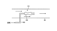
[第2実施形態]
図3は、第2実施形態の原子力発電プラントにおけるアニュラス空気浄化装置を表す概略図、図4は、非常用空気排出装置を表す概略図である。なお、上述した実施形態と同様の機能を有する部材には、同一の符号を付して詳細な説明は省略する。
[Second Embodiment]
FIG. 3 is a schematic diagram showing an annulus air purification device in the nuclear power plant of the second embodiment, and FIG. 4 is a schematic diagram showing an emergency air discharge device. In addition, the same code | symbol is attached | subjected to the member which has the same function as embodiment mentioned above, and detailed description is abbreviate | omitted.
第2実施形態において、図3及び図4に示すように、原子炉格納容器11は、外部遮へい壁71との間にアニュラス72が設けられており、このアニュラス72は、アニュラス空気浄化装置76が接続されている。アニュラス空気浄化装置76において、大気放出ライン81は、一端部がアニュラス72に連結され、他端部が排気塔82を介して大気に開放している。この大気放出ライン81は、アニュラス72と排気塔82との間に、アニュラス72側から排気弁83、空気浄化フィルタユニット84、電動式空気排出ファン85、放出弁86が設けられている。
In the second embodiment, as shown in FIGS. 3 and 4, the
また、アニュラス空気浄化装置76は、大気放出ライン81に電動式空気排出ファン85を迂回するように迂回ライン88が設けられており、この迂回ライン88に蒸気駆動式空気排出装置101が設けられている。この蒸気駆動式空気排出装置101は、エジェクタ102を有しており、原子力発電プラントの二次系蒸気により駆動することができる。即ち、蒸気分岐配管90(図2参照)は、蒸気駆動式空気排出装置101まで延出されている。即ち、エジェクタ102は、迂回ライン88を構成する配管内に大気放出ライン81における放出側を向いて配置されている。このエジェクタ102は、基端部側に配管103の一端部が連結され、配管103の他端部が迂回ライン88の外部に出て蒸気分岐配管90が連結されている。なお、エジェクタ102における前方に整流器を設けるとよい。
Further, the annulus
そのため、電源装置87が喪失したとき、蒸気を蒸気分岐配管90により蒸気駆動式空気排出装置101に供給することで、蒸気によりこの蒸気駆動式空気排出装置101を駆動することができる。即ち、蒸気駆動式空気排出装置101は、蒸気が供給されると、エジェクタ102が迂回ライン88の配管内に、大気放出ライン81における放出側に向けて蒸気を噴射する。すると、この蒸気は、迂回ライン88の配管内のガスを大気放出ライン81における放出側に向けて移動することとなり、アニュラス72内の雰囲気が吸引される。そのため、アニュラス72内の雰囲気は、大気放出ライン81及び迂回ライン88を大気放出側に流れることとなり、アニュラス72内の雰囲気を空気浄化フィルタユニット84により浄化し、浄化後の空気を排気塔82から大気へ放出することができる。そして、アニュラス72内の負圧を確保することで、原子炉格納容器11内に漏れた一次冷却材中の放射性物質を含むガスがアニュラス72内に漏洩したとしても、このアニュラス72内に閉じ込めることができる。
Therefore, when the
このように第2実施形態のアニュラス空気浄化装置にあっては、大気放出ライン81に電動式空気排出ファン85を迂回するように蒸気駆動式空気排出装置101を設け、この蒸気駆動式空気排出装置101としてエジェクタ102を設けている。
Thus, in the annulus air purification device of the second embodiment, the steam-driven
従って、電源装置87が喪失したとき、電動式空気排出ファン85に代えて蒸気駆動式空気排出装置101が作動し、アニュラス72内の雰囲気を空気浄化フィルタユニット84により浄化してから排出する。そのため、アニュラス72内の雰囲気を空気浄化フィルタユニット84により浄化してから排出することができると共に、内部を負圧に維持して漏洩した放射性物質を閉じ込めることができる。
Therefore, when the
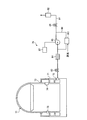
[第3実施形態]
図5は、第3実施形態の原子力発電プラントにおけるアニュラス空気浄化装置を表す概略図である。なお、上述した実施形態と同様の機能を有する部材には、同一の符号を付して詳細な説明は省略する。
[Third Embodiment]
FIG. 5 is a schematic diagram illustrating an annulus air purifying device in the nuclear power plant according to the third embodiment. In addition, the same code | symbol is attached | subjected to the member which has the same function as embodiment mentioned above, and detailed description is abbreviate | omitted.
第3実施形態において、図5に示すように、原子炉格納容器11は、外部遮へい壁71との間にアニュラス72が設けられており、このアニュラス72は、アニュラス空気浄化装置76が接続されている。アニュラス空気浄化装置76において、大気放出ライン81は、一端部がアニュラス72に連結され、他端部が排気塔82を介して大気に開放している。この大気放出ライン81は、アニュラス72と排気塔82との間に、アニュラス72側から排気弁83、空気浄化フィルタユニット84、電動式空気排出ファン85、放出弁86が設けられている。アニュラス空気浄化装置76は、大気放出ライン81に電動式空気排出ファン85を迂回するように迂回ライン88が設けられており、この迂回ライン88に蒸気駆動式空気排出装置89が設けられている。
In the third embodiment, as shown in FIG. 5, the
更に、アニュラス空気浄化装置76は、アニュラス72に冷却装置としての複数のヒートパイプ111が設けられている。このヒートパイプ111は、外部遮へい壁71における上部壁71aに鉛直方向に沿って固定され、下部がアニュラス72内に位置し、上部が外部に露出している。このヒートパイプ111は、図示しないが、密閉容器内に少量の作動液を真空封入し、内壁に毛細管構造としてのウィックを設けたものである。そのため、ヒートパイプ111は、アニュラス72内に位置する加熱部(下部)が加熱されると、加熱部で作動液が蒸発(蒸発潜熱の吸収)し、発生した蒸気が上昇して低温部、つまり、アニュラス72の外部に位置する上部に移動する。すると、この蒸気が低温部(上部)で凝縮(蒸発潜熱の放出)し、凝縮した作動液が毛細管現象で加熱部(下部)に環流する。その結果、この一連の相変化が連続的に生じることで、アニュラス72内の空気が有する熱を早期に外部へ移動して放熱し、アニュラス72内の雰囲気を冷却することができる。
Further, in the annulus
そのため、電源装置87が喪失したとき、蒸気を蒸気分岐配管90により蒸気駆動式空気排出装置89に供給することで、蒸気によりこの蒸気駆動式空気排出装置89を駆動することができる。すると、アニュラス72内の雰囲気は、大気放出ライン81及び迂回ライン88を大気放出側に流れることとなり、アニュラス72内の雰囲気を空気浄化フィルタユニット84により浄化し、浄化後の空気を排気塔82から大気へ放出することができる。そして、アニュラス72内の負圧を確保することで、原子炉格納容器11内に漏れた一次一次冷却材中の放射性物質を含むガスがアニュラス72内に漏洩したとしても、このアニュラス72内に閉じ込めることができる。
Therefore, when the
また、このとき、原子炉格納容器11内に漏れた一次冷却材中の放射性物質を含むガス(空気と蒸気の混合気体)がアニュラス72内に漏洩する可能性があるが、このガスを含むアニュラス72内の雰囲気中の蒸気がヒートパイプ111により冷却されることで凝縮し、体積が減少するため、アニュラス72内の負圧が維持され、放射性物質の外部漏洩が抑制される。
At this time, a gas containing a radioactive substance in the primary coolant leaked into the reactor containment vessel 11 (a mixed gas of air and steam) may leak into the
このように第3実施形態のアニュラス空気浄化装置にあっては、大気放出ライン81に電動式空気排出ファン85を迂回するように蒸気駆動式空気排出装置89を設けと共に、アニュラス72に冷却装置としての複数のヒートパイプ111を設けている。
As described above, in the annulus air purification device of the third embodiment, the steam-driven
従って、電源装置87が喪失したとき、電動式空気排出ファン85に代えて蒸気駆動式空気排出装置89が作動し、アニュラス72内の雰囲気を空気浄化フィルタユニット84により浄化してから排出する。そのため、アニュラス72内の雰囲気を空気浄化フィルタユニット84により浄化してから排出することができると共に、内部を負圧に維持して漏洩した放射性物質を閉じ込めることができる。また、このとき、原子炉格納容器11内に漏れた一次冷却材中の放射性物質を含むガス(空気と蒸気の混合気体)がアニュラス72内に漏洩しても、アニュラス72内雰囲気中の蒸気は、ヒートパイプ111により冷却されることで凝縮して体積が減少するため、アニュラス72内の負圧の維持に貢献し、アニュラス72内の放射性物質の外部漏洩を抑制することができる。
Therefore, when the
なお、上述した実施形態では、原子炉格納容器11の外側に遮へい壁71を設け、原子炉格納容器11と遮へい壁71との間にアニュラス72を設けたが、この構成に限定されるものではない。例えば、原子炉格納容器11に隣接して建屋を設け、原子炉格納容器11とこの建屋との間にアニュラスを設けてもよい。
In the embodiment described above, the shielding
また、上述した実施形態では、蒸気分岐配管90を設けることで、蒸気発生器13で生成した二次系蒸気を蒸気駆動式空気排出装置89に供給可能としたが、蒸気駆動式空気排出装置89を駆動するための蒸気は、蒸気発生器13で生成した二次系蒸気に限定されるものではなく、プラント内で各種機器を駆動するための蒸気や空気などであってもよい。
Further, in the above-described embodiment, by providing the
11 原子炉格納容器
12 加圧水型原子炉
13 蒸気発生器
18,34 配管
19 蒸気タービン
23 発電機
28 復水器
44 主蒸気逃がし弁
46 主蒸気安全弁
48 補助給水配管
49 補助給水ポンプ
51,90 冷却水分岐配管
51a 開閉弁
71 外部遮へい壁(壁部)
72 アニュラス
73 アニュラスシール
76 アニュラス空気浄化装置
81 大気放出ライン
82 排気塔
83 排気弁
84 空気浄化フィルタユニット
85 電動式空気排出ファン(電動式空気排出装置)
86 放出弁
87 電源装置
88 迂回ライン
89 蒸気駆動式空気排出ファン(蒸気駆動式空気排出装置)
90 蒸気分岐配管
101 蒸気駆動式空気排出装置
102 エジェクタ
111 ヒートパイプ(冷却装置)
11
72
86
90 Steam branch piping 101 Steam driven
Claims (7)
端部が前記アニュラスに連結される大気放出ラインと、
前記大気放出ラインに設けられる電動式空気排出装置と、
前記大気放出ラインに設けられる空気浄化フィルタと、
前記大気放出ラインに前記電動式空気排出装置を迂回するように設けられる蒸気駆動式空気排出装置と、
を有することを特徴とするアニュラス空気浄化装置。 In the annulus air purifying apparatus in which an annulus is provided between a reactor containment vessel and a wall portion installed on the outside, and maintains and purifies the negative pressure in the atmosphere inside the annulus,
An atmospheric discharge line having an end connected to the annulus;
An electric air discharge device provided in the atmospheric discharge line;
An air purification filter provided in the atmospheric discharge line;
A steam-driven air discharge device provided to bypass the electric air discharge device in the atmospheric discharge line;
An annulus air purifying device characterized by comprising:
前記原子炉格納容器と外側に設置される壁部との間に設けられるアニュラスと、
前記アニュラス内雰囲気の負圧維持及び浄化をする請求項1から請求項5のいずれか一項に記載のアニュラス空気浄化装置と、
前記蒸気発生器で生成した二次系蒸気を前記蒸気駆動式空気排出装置に供給可能な蒸気供給ラインと、
を有することを特徴とする原子力発電プラント。 A reactor containment vessel for storing a reactor and a steam generator inside;
An annulus provided between the reactor containment vessel and a wall portion installed on the outside;
An annulus air purification device according to any one of claims 1 to 5, which maintains and purifies the negative pressure in the atmosphere inside the annulus,
A steam supply line capable of supplying secondary steam generated by the steam generator to the steam-driven air discharge device;
A nuclear power plant characterized by comprising:
Priority Applications (1)
| Application Number | Priority Date | Filing Date | Title |
|---|---|---|---|
| JP2013256392A JP2015114203A (en) | 2013-12-11 | 2013-12-11 | Annulus air purification system and nuclear power plant |
Applications Claiming Priority (1)
| Application Number | Priority Date | Filing Date | Title |
|---|---|---|---|
| JP2013256392A JP2015114203A (en) | 2013-12-11 | 2013-12-11 | Annulus air purification system and nuclear power plant |
Publications (1)
| Publication Number | Publication Date |
|---|---|
| JP2015114203A true JP2015114203A (en) | 2015-06-22 |
Family
ID=53528127
Family Applications (1)
| Application Number | Title | Priority Date | Filing Date |
|---|---|---|---|
| JP2013256392A Pending JP2015114203A (en) | 2013-12-11 | 2013-12-11 | Annulus air purification system and nuclear power plant |
Country Status (1)
| Country | Link |
|---|---|
| JP (1) | JP2015114203A (en) |
Cited By (2)
| Publication number | Priority date | Publication date | Assignee | Title |
|---|---|---|---|---|
| JP2019027748A (en) * | 2017-08-03 | 2019-02-21 | 日立Geニュークリア・エナジー株式会社 | Condensate storage facility |
| JP7454517B2 (en) | 2021-02-10 | 2024-03-22 | 三菱重工業株式会社 | reactor containment vessel |
-
2013
- 2013-12-11 JP JP2013256392A patent/JP2015114203A/en active Pending
Cited By (2)
| Publication number | Priority date | Publication date | Assignee | Title |
|---|---|---|---|---|
| JP2019027748A (en) * | 2017-08-03 | 2019-02-21 | 日立Geニュークリア・エナジー株式会社 | Condensate storage facility |
| JP7454517B2 (en) | 2021-02-10 | 2024-03-22 | 三菱重工業株式会社 | reactor containment vessel |
Similar Documents
| Publication | Publication Date | Title |
|---|---|---|
| CN109243634B (en) | Reactor safety system | |
| CA2870859C (en) | Defense in depth safety paradigm for nuclear reactor | |
| JP5876320B2 (en) | Nuclear power plant | |
| KR101654096B1 (en) | Self-diagnostic Unmanned Reactor | |
| CN103413581B (en) | passive containment cooling system | |
| CN107665742B (en) | It is active to meet an urgent need residual heat removal system with the passive naval reactor that combines | |
| CN104733060A (en) | Passive residual heat removal system of marine nuclear power device | |
| KR20140112198A (en) | Safety System of Ocean System-integrated Modular Advanced Reactor | |
| CN204242601U (en) | Non-passive safety cooling system | |
| CN104361913A (en) | Secondary side passive waste heat removal system | |
| CN203366766U (en) | Secondary side discharge system for alleviating vapor generator's heat-transfer pipe cracking accidents | |
| CN104766637A (en) | Safety injection integrated system | |
| CN112700893A (en) | Waste heat discharge system and method and nuclear power system | |
| CN107833642A (en) | Heat exchanger is located at the outer marine PWR Passive residual heat removal system of water tank | |
| JP2011128090A (en) | Nuclear power plant using kalina cycle | |
| KR101224023B1 (en) | Residual heat removal and containment cooling system using passive auxiliary feed-water system for pressurized water reactor | |
| RU96283U1 (en) | PASSIVE HEAT REMOVAL SYSTEM THROUGH A STEAM GENERATOR | |
| JP2015114203A (en) | Annulus air purification system and nuclear power plant | |
| RU2408097C1 (en) | Cleaning device of inter-cover space | |
| CN204242602U (en) | Secondary side passive residual heat guiding system | |
| CN118711853A (en) | Pressurized water reactor emergency residual heat removal system | |
| JP2013007727A (en) | Nuclear reactor emergency countermeasure method | |
| KR101191655B1 (en) | Passive refill and recovery system for steam generator | |
| CN108447570A (en) | Naval reactor and its Passive residual heat removal system | |
| KR20140028537A (en) | Inherent safety water cooled reactor system for thermal desalination |