JP2015114185A - Partial discharge detection method and partial discharge detection apparatus - Google Patents
Partial discharge detection method and partial discharge detection apparatus Download PDFInfo
- Publication number
- JP2015114185A JP2015114185A JP2013255684A JP2013255684A JP2015114185A JP 2015114185 A JP2015114185 A JP 2015114185A JP 2013255684 A JP2013255684 A JP 2013255684A JP 2013255684 A JP2013255684 A JP 2013255684A JP 2015114185 A JP2015114185 A JP 2015114185A
- Authority
- JP
- Japan
- Prior art keywords
- partial discharge
- inspection object
- impulse voltage
- measurement signal
- signal
- Prior art date
- Legal status (The legal status is an assumption and is not a legal conclusion. Google has not performed a legal analysis and makes no representation as to the accuracy of the status listed.)
- Granted
Links
Images

Landscapes
- Testing Relating To Insulation (AREA)
Abstract
Description
本発明は、電気機器などの検査対象物の内部で発生する部分放電を検出するための手法およびそのための装置に関する。 The present invention relates to a technique for detecting a partial discharge generated inside an inspection object such as an electric device and an apparatus therefor.
電力用の変電機器や配電機器に代表される電気機器における通常運転時の内部異常の代表として、機器内部で発生する部分放電が挙げられる。部分放電は、電気機器の絶縁破壊(全路破壊)の前駆現象であり、部分放電を確実に検出する技術を確立することで電気機器の絶縁破壊を予防することが可能となる。 A typical example of internal abnormality during normal operation in electrical equipment represented by power substation equipment and power distribution equipment is partial discharge that occurs inside the equipment. Partial discharge is a precursor phenomenon of dielectric breakdown (all-path breakdown) of electrical equipment, and it is possible to prevent electrical breakdown of electrical equipment by establishing a technique for reliably detecting partial discharge.
一般的に、電気機器において部分放電が発生し得る高電圧充電部は、露出していることはなく、絶縁性の容器または接地電位の金属筐体(タンク)内部に収納されている。つまり、部分放電が発生し得る高電圧充電部は、他の構造物により覆われており、直接観測することができない。それに加えて、機器内部で発生する部分放電に伴う信号は非常に微弱であり、さらに電気機器のフィールドでの運転時には種々の外来ノイズが部分放電に伴う信号に重畳するため、部分放電に伴う信号をノイズ信号と分別して抽出する工夫が必要になる。 Generally, a high-voltage charging unit that can cause partial discharge in an electric device is not exposed and is housed in an insulating container or a metal casing (tank) having a ground potential. That is, the high-voltage charging part where partial discharge can occur is covered with another structure and cannot be directly observed. In addition, the signal accompanying partial discharge generated inside the equipment is very weak, and various external noises are superimposed on the signal accompanying partial discharge when operating in the field of electrical equipment. It is necessary to devise a method to extract the noise separately from the noise signal.
電気機器の通常運転時における部分放電の検出手法として、音響(AE:Acoustic Emission)センサを用いる方法が知られている。 As a method for detecting partial discharge during normal operation of an electric device, a method using an acoustic (AE) sensor is known.
例えば、特開2008−180681号公報(特許文献1)は、変圧器内の部分放電によって生じる弾性波(超音波)信号を検出するアコースティックエミッションセンサと、部分放電発生時に接地線を流れる放電パルス信号を検出する電流センサとを含む診断システムを開示する。また、特開2008−232973号公報(特許文献2)は、部分放電によるアースに流れる電流パルスを検出する電流検出器と、部分放電による音響信号を検出する超音波センサとを含む部分放電判定装置を開示する。 For example, Japanese Patent Laying-Open No. 2008-180681 (Patent Document 1) discloses an acoustic emission sensor that detects an elastic wave (ultrasound) signal generated by partial discharge in a transformer, and a discharge pulse signal that flows through a ground line when partial discharge occurs. A diagnostic system is disclosed that includes a current sensor for detecting a current sensor. Japanese Patent Laying-Open No. 2008-2322973 (Patent Document 2) discloses a partial discharge determination device including a current detector that detects a current pulse flowing to the ground due to partial discharge, and an ultrasonic sensor that detects an acoustic signal due to partial discharge. Is disclosed.
これらの先行技術文献に開示される技術は、電流センサを用いて部分放電の発生に伴って生じるタンク壁面または接地線を流れる電流を検出するとともに、音響センサを用いて部分放電の発生に伴って生じる音響信号を検出し、部分放電の発生に伴って生じる電気信号と音響信号との空間伝播速度の違いを利用して、部分放電の発生の有無を判断する。 The technologies disclosed in these prior art documents detect current flowing through a tank wall surface or a ground line generated by the occurrence of partial discharge using a current sensor, and accompany generation of partial discharge using an acoustic sensor. The generated acoustic signal is detected, and the presence / absence of the partial discharge is determined using the difference in the spatial propagation speed between the electrical signal and the acoustic signal generated in association with the generation of the partial discharge.
すなわち、機器内部で部分放電が発生した場合、まず部分放電に起因する電流パルスが電流センサによって検出される。次に、高電圧充電部と音響センサとの間の距離で決まる所定時間後に、音響センサによって部分放電に起因する音響信号が検出される。電流センサにより検出された電流信号が電気機器に対して印加される交流電圧の周期と同期し、かつ電流センサによる検出信号と音響センサによる検出信号との間の時間差が略同一になるケースが所定時間内に所定数ある場合に部分放電と判断される。このような手法を採用することで、部分放電に伴う信号とノイズ信号との分別が可能になる。 That is, when a partial discharge occurs inside the device, first, a current pulse due to the partial discharge is detected by the current sensor. Next, after a predetermined time determined by the distance between the high-voltage charging unit and the acoustic sensor, an acoustic signal due to partial discharge is detected by the acoustic sensor. There is a predetermined case in which the current signal detected by the current sensor is synchronized with the cycle of the AC voltage applied to the electrical device, and the time difference between the detection signal by the current sensor and the detection signal by the acoustic sensor is substantially the same. If there is a predetermined number within the time, it is determined that the partial discharge. By adopting such a method, it becomes possible to separate a signal accompanying a partial discharge from a noise signal.
上述の先行技術文献に開示される技術は、電気機器がフィールドに設置された後、経年劣化などによって生じる絶縁破壊を予防するための予防保全技術に向けられており、基本的には、商用電源が印加される通常運転時に適用される。 The technology disclosed in the above-mentioned prior art documents is directed to preventive maintenance technology for preventing dielectric breakdown caused by deterioration over time after electrical equipment is installed in the field. It is applied during normal operation where is applied.
一方、電力用の変電機器や配電機器といった電気機器には、製品出荷前に、絶縁試験の一つとして雷インパルス耐電圧試験が課せられる場合が多い。標準規格(例えば、電気規格調査会が定める標準規格JEC0103(2005))上は、規定の電圧波形を有するインパルス電圧を印加した際に対象の電気機器が絶縁破壊しなければ、合格であるとされている。しかしながら、製品の絶縁信頼性を保証するため、および、印加電圧に対する絶縁破壊までの裕度を明確にしておくためにも、絶縁破壊の前駆現象である部分放電を検出しておくことが重要である。すなわち、雷インパルス耐電圧試験時においても、部分放電を検出したいというニーズが存在する。 On the other hand, a lightning impulse withstand voltage test is often imposed as an insulation test on electrical devices such as power transformers and power distribution devices before shipment. According to the standard (for example, the standard JEC0103 (2005) defined by the Electrical Standards Committee), when an impulse voltage having a prescribed voltage waveform is applied and the target electrical device does not break down, it is considered to be acceptable. ing. However, it is important to detect partial discharge, which is a precursor phenomenon of dielectric breakdown, in order to guarantee the insulation reliability of the product and to clarify the tolerance to the dielectric breakdown with respect to the applied voltage. is there. That is, there is a need to detect a partial discharge even during a lightning impulse withstand voltage test.
このような部分放電を検出したいというニーズに対して、上述したような先行技術文献に開示される音響センサを用いた手法をそのまま適用することはできない。なぜならば、雷インパルス耐電圧試験時には、より大きなノイズが生じるため、通常運転時での試験が想定されている先行技術文献に記載の手法では、このノイズの影響を受けて部分放電の発生を適切に検出することができないからである。 For the need to detect such partial discharge, the method using the acoustic sensor disclosed in the prior art document as described above cannot be applied as it is. This is because, during the lightning impulse withstand voltage test, a larger noise is generated. Therefore, the method described in the prior art document that is assumed to be a test during normal operation appropriately generates partial discharge under the influence of this noise. This is because it cannot be detected.
本発明は、このような課題に鑑みてなされたものであって、その目的は、検査対象物の充電部にインパルス電圧を印加することで発生する部分放電を、検査対象物に装着された音響センサを用いて検出できる部分放電検出方法および部分放電検出装置を提供することである。 The present invention has been made in view of such a problem, and an object of the present invention is to provide a partial discharge generated by applying an impulse voltage to a charging portion of an inspection object, and an acoustic sound attached to the inspection object. It is an object to provide a partial discharge detection method and a partial discharge detection device that can be detected using a sensor.
本発明のある局面に係る部分放電検出方法は、検査対象物の充電部に第1のインパルス電圧を印加するステップと、第1のインパルス電圧の印加が開始されたタイミングを取得するステップと、検査対象物の外面に装着された音響センサによって第1の測定信号を取得するステップと、第1の測定信号にローパスフィルタを適用することで第2の測定信号を取得するステップと、第2の測定信号から検査対象物の機械振動に起因するノイズ成分を除去することで第3の測定信号を取得するステップと、取得されたタイミングを基準として、検査対象物における充電部と音響センサとの位置関係に応じて定まる有効測定期間内に現れる、第3の測定信号の時間波形に基づいて、検査対象物での部分放電の発生の有無を判断するステップとを含む。ノイズ成分は、検査対象物で部分放電を発生させない、第1のインパルス電圧より低い第2のインパルス電圧を検査対象物の充電部に印加したときに、音響センサによって取得される第4の測定信号に基づいて決定される。 A partial discharge detection method according to an aspect of the present invention includes a step of applying a first impulse voltage to a charging unit of an inspection object, a step of acquiring a timing at which application of the first impulse voltage is started, and an inspection Acquiring a first measurement signal by an acoustic sensor mounted on the outer surface of the object, acquiring a second measurement signal by applying a low-pass filter to the first measurement signal, and second measurement A step of acquiring a third measurement signal by removing a noise component caused by mechanical vibration of the inspection object from the signal, and a positional relationship between the charging unit and the acoustic sensor in the inspection object on the basis of the acquired timing Determining whether or not partial discharge has occurred in the inspection object based on the time waveform of the third measurement signal that appears within an effective measurement period determined according toThe noise component is a fourth measurement signal acquired by the acoustic sensor when a second impulse voltage lower than the first impulse voltage, which does not cause partial discharge in the inspection object, is applied to the charging unit of the inspection object. To be determined.
好ましくは、部分放電検出方法は、検査対象物の充電部に第2のインパルス電圧を印加するステップと、音響センサによって第4の測定信号を取得するステップと、第4の測定信号にローパスフィルタを適用することでノイズ成分を決定するための参照信号を取得するステップとをさらに含む。 Preferably, in the partial discharge detection method, a step of applying a second impulse voltage to a charging unit of the inspection object, a step of acquiring a fourth measurement signal by an acoustic sensor, and a low-pass filter for the fourth measurement signal Applying a reference signal for determining a noise component by applying.
好ましくは、部分放電検出方法は、検査対象物の外面に複数の音響センサを装着し、第1の測定信号を取得するステップと、第2の測定信号を取得するステップと、第3の測定信号を取得するステップと、検査対象物での部分放電の発生の有無を判断するステップとを、複数の音響センサの別にそれぞれ実行するステップと、検査対象物で部分放電が発生していると判断されると、複数の音響センサからそれぞれ取得された複数の第3の測定信号において部分放電の発生を示す時間波形が現れるタイミングの差に基づいて、部分放電の発生位置を標定するステップとをさらに含む。 Preferably, in the partial discharge detection method, a plurality of acoustic sensors are attached to the outer surface of the inspection object, the first measurement signal is obtained, the second measurement signal is obtained, and the third measurement signal is obtained. And the step of determining whether or not partial discharge has occurred in the inspection object separately from the plurality of acoustic sensors, and determining that partial discharge has occurred in the inspection object. Then, the method further includes the step of locating the occurrence position of the partial discharge based on the difference in timing at which the time waveforms indicating the occurrence of the partial discharge appear in the plurality of third measurement signals respectively acquired from the plurality of acoustic sensors. .
好ましくは、タイミングを取得するステップは、第1のインパルス電圧の印加によって生じる電磁波の変化を電磁波センサによって検出するステップを含む。 Preferably, the step of acquiring the timing includes a step of detecting, by an electromagnetic wave sensor, a change in the electromagnetic wave caused by the application of the first impulse voltage.
好ましくは、タイミングを取得するステップは、第1のインパルス電圧の印加によって生じる電流の変化を電流センサによって検出するステップを含む。 Preferably, the step of acquiring the timing includes a step of detecting a change in current caused by application of the first impulse voltage by a current sensor.
本発明の別の局面によれば、検査対象物の充電部にインパルス電圧を印加することで発生する部分放電を検出する部分放電検出装置が提供される。部分放電検出装置は、第1のインパルス電圧の検査対象物への印加が開始されたタイミングを取得するタイミング取得手段と、検査対象物の外面に装着される音響センサと、音響センサで検出された第1の測定信号にローパスフィルタを適用することで第2の測定信号を出力する第1の信号処理部と、第2の測定信号から検査対象物の機械振動に起因するノイズ成分を除去することで第3の測定信号を出力する第2の信号処理部と、取得されたタイミングを基準として、検査対象物における充電部と音響センサとの位置関係に応じて定まる有効測定期間内に現れる、第3の測定信号の時間波形に基づいて、検査対象物での部分放電の発生の有無を判断する判断手段とを含む。ノイズ成分は、検査対象物で部分放電を発生させない、第1のインパルス電圧より低い第2のインパルス電圧を検査対象物の充電部に印加したときに、音響センサによって取得される第4の測定信号に基づいて決定される。 According to another situation of this invention, the partial discharge detection apparatus which detects the partial discharge which generate | occur | produces by applying an impulse voltage to the charge part of a test subject is provided. The partial discharge detection device is detected by a timing acquisition means for acquiring a timing at which application of the first impulse voltage to the inspection object is started, an acoustic sensor mounted on the outer surface of the inspection object, and the acoustic sensor. A first signal processing unit that outputs a second measurement signal by applying a low-pass filter to the first measurement signal, and a noise component caused by mechanical vibration of the inspection object is removed from the second measurement signal. The second signal processing unit that outputs the third measurement signal at the second time, and the second signal processing unit that appears within an effective measurement period determined according to the positional relationship between the charging unit and the acoustic sensor in the inspection object, based on the acquired timing. And determining means for determining whether or not partial discharge has occurred in the inspection object based on the time waveform of the measurement signal of No. 3. The noise component is a fourth measurement signal acquired by the acoustic sensor when a second impulse voltage lower than the first impulse voltage, which does not cause partial discharge in the inspection object, is applied to the charging unit of the inspection object. To be determined.
本発明によれば、検査対象物の充電部にインパルス電圧を印加することで発生する部分放電を、検査対象物に装着された音響センサを用いて検出できる部分放電検出方法および部分放電検出装置を実現できる。 According to the present invention, there is provided a partial discharge detection method and a partial discharge detection device capable of detecting a partial discharge generated by applying an impulse voltage to a charging unit of an inspection object using an acoustic sensor attached to the inspection object. realizable.
以下、本発明の実施の形態に係る部分放電検出方法および部分放電検出装置について、図面を参照しつつ説明する。以下の実施の形態の説明においては、図中の同一または相当部分には同一符号を付してその説明は繰返さない。 Hereinafter, a partial discharge detection method and a partial discharge detection device according to embodiments of the present invention will be described with reference to the drawings. In the following description of the embodiments, the same or corresponding parts in the drawings will be denoted by the same reference numerals and description thereof will not be repeated.
以下の説明においては、検査対象物である電気機器の典型例を電力用変圧器としてその内容について説明する。しかしながら、本発明に係る部分放電検出方法および部分放電検出装置の検査対象物としては、電力用の変電機器や配電機器などの任意の電気機器を対象とすることができる。例えば、外鉄型変圧器、内鉄型変圧器、絶縁開閉装置などを検査対象物とすることができる。 In the following description, a typical example of an electric device that is an inspection object will be described as a power transformer. However, the inspection object of the partial discharge detection method and the partial discharge detection device according to the present invention can be any electric device such as a power transformer or distribution device. For example, an outer iron type transformer, an inner iron type transformer, an insulated switchgear, and the like can be used as inspection objects.
[A.関連技術およびその課題]
まず、本発明の関連技術およびその関連技術における課題などについて説明する。
[A. Related technologies and issues]
First, a related technique of the present invention and problems in the related technique will be described.
電力用の変電機器や配電機器といった電気機器に対して、製品出荷前に実施される絶縁試験の一つとして雷インパルス耐電圧試験がある。この試験は、電力用変圧器などの電気機器が通常運転中に、外部で生じた雷サージや開閉サージ等の異常電圧波形が課電された場合であっても絶縁性能を保証するための試験である。具体的には、標準規格で定められた電圧波形を電気機器へ印加した場合であっても、絶縁破壊しないことが求められる。但し、製品の絶縁信頼性を保証するため、および、印加電圧に対する絶縁破壊までの裕度を明確にしておくためにも、絶縁破壊の前駆現象である部分放電を検出しておくことが重要である。 A lightning impulse withstand voltage test is one of the insulation tests performed on electrical devices such as power transformers and power distribution devices before product shipment. This test is to ensure insulation performance even when an abnormal voltage waveform such as lightning surge or switching surge generated outside is applied during normal operation of electrical equipment such as power transformers. It is. Specifically, it is required that the dielectric breakdown does not occur even when a voltage waveform defined in the standard is applied to an electrical device. However, it is important to detect partial discharge, which is a precursor phenomenon of dielectric breakdown, in order to guarantee the insulation reliability of the product and to clarify the tolerance to dielectric breakdown for the applied voltage. is there.
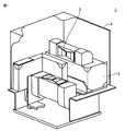
図1は、検査対象物の一例である電力用変圧器1の構成を示す斜視断面図である。図1においては、各構成の一部をカットして示している。図1に示す電力用変圧器1は、油冷式の外鉄型電力用変圧器であり、主として、鉄心2と、鉄心2に巻回された巻線からなるコイル3と、鉄心2およびコイル3を収納するタンク4とを含む。タンク4内には図示しない絶縁油が充填されており、絶縁油には鉄心2およびコイル3が浸漬されている。なお、冷却媒体としては、絶縁油ではなく、六フッ化硫黄などのガスあるいは空気などを用いてもよい。
FIG. 1 is a perspective sectional view showing a configuration of a
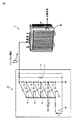
図2は、雷インパルス耐電圧試験の概要を示す模式図である。図2を参照して、検査対象物である電力用変圧器1の充電部(典型的には、端子部)は、インパルス電圧発生装置10と電気的に接続される。インパルス電圧発生装置10は、その発生するインパルス電圧を検査対象物である電力用変圧器1へ印加する。
FIG. 2 is a schematic diagram showing an outline of a lightning impulse withstand voltage test. Referring to FIG. 2, a charging unit (typically, a terminal unit) of
ここで、雷インパルス耐電圧試験時に用いられるインパルス電圧発生装置10の動作原理を説明する。インパルス電圧発生装置10は、入力端子対16に並列接続された複数のコンデンサ12を含む。入力端子対16を介して入力電圧Vが印加されると、並列接続された複数のコンデンサ12それぞれが入力電圧Vに応じた電圧まで充電される。その後、複数のコンデンサ12にそれぞれ関連付けて設けられている複数の球ギャップ14の各々を、同時に接触させることで、複数のコンデンサ12は模擬的に直列接続になり、放電が開始される。
Here, the operation principle of the
放電が開始されると、インパルス電圧発生装置10と検査対象物である電力用変圧器1とを含む回路定数によって定まる、波頭長(立ち上がり時間)および波尾長(立ち下がり時間)の波形を有するインパルス電圧が出力される。インパルス電圧発生装置10の出力側には、放電抵抗17および波頭長調整用コンデンサ18が接地線との間にそれぞれ接続されている。標準規格によって定められた電圧波形が検査対象物へ印加されるように、放電抵抗17および波頭長調整用コンデンサ18の大きさが調整される。
When the discharge is started, the impulse having a waveform having a wavefront length (rise time) and a wave tail length (fall time), which is determined by a circuit constant including the
インパルス電圧発生装置10を用いる雷インパルス耐電圧試験では、その動作原理上、インパルス電圧の出力と同時に、球ギャップ14間の火花放電に起因する非常に強い電磁ノイズが放射される。この電磁ノイズの存在によって、電力用変圧器1の内部で発生する部分放電を検出することが非常に困難となる。
In the lightning impulse withstand voltage test using the
高電圧の電気機器における部分放電の検出手法として一般的に用いられる方法としては、(1)部分放電の発生に伴って発生する電磁波を電磁波センサ(アンテナ)を用いて検出する電磁波法、(2)部分放電の発生に伴って流れる電流パルスを検出する方法、(3)部分放電の発生に伴って発生する弾性波信号を音響センサによって検出する手法、などが知られている。 Methods commonly used as a method for detecting partial discharge in high-voltage electrical equipment include (1) an electromagnetic wave method for detecting an electromagnetic wave generated with the occurrence of partial discharge using an electromagnetic wave sensor (antenna), (2 There are known a method of detecting a current pulse flowing with the occurrence of partial discharge, and a method of detecting an acoustic wave signal generated with the occurrence of partial discharge with an acoustic sensor.
(1)の電磁波法を雷インパルス耐電圧試験時に用いると、部分放電に起因する電磁波がインパルス電圧発生装置10からの電磁ノイズに埋没してしまい、部分放電を検出することができない。
When the electromagnetic wave method (1) is used during a lightning impulse withstand voltage test, the electromagnetic waves resulting from the partial discharge are buried in the electromagnetic noise from the
(2)の電流パルスを検出する方法については、インパルス電圧発生装置10からの電磁ノイズが検査対象物の静電容量を介して接地線へ流れるので、部分放電に起因する電流パルスに重畳してしまい、部分放電を検出することができない。
Regarding the method of detecting the current pulse of (2), since electromagnetic noise from the
(3)の音響センサを用いる従来の方法についても以下のような課題がある。例えば、上述の特開2008−180681号公報(特許文献1)に開示される方法では、電流センサを用いて部分放電の発生に伴って生じるタンク壁面または接地線を流れる電流パルスを検出する必要があるが、インパルス電圧発生装置10から放射される非常に強い電磁ノイズの影響を受けて、部分放電に起因する電流パルスを正しく検出することができない。また、電磁ノイズが検査対象物の静電容量を介して接地線へ流れるので、部分放電に起因する電流パルスに重畳してしまうという問題もある。
The conventional method using the acoustic sensor (3) also has the following problems. For example, in the method disclosed in the above-mentioned Japanese Patent Application Laid-Open No. 2008-180681 (Patent Document 1), it is necessary to detect a current pulse flowing through a tank wall surface or a ground line, which is generated when a partial discharge occurs, using a current sensor. However, under the influence of extremely strong electromagnetic noise radiated from the
さらに、早い立ち上がり時間をもつインパルス電圧が検査対象物に印加されると、充電電流が瞬間的に流れることになり、検査対象物自体に機械振動が生じる。本願発明者らは、このインパルス電圧の印加によって生じる機械振動によって、部分放電の適切な検出が阻害されるという新たな課題を見出した。すなわち、インパルス電圧を検査対象物である電力用変圧器1に印加すると、その静電容量を介して充電電流が瞬間的に流れる。充電電流が電力用変圧器1のコイル3を流れることで、各巻線間には物理的な力が発生し、コイル3には機械振動が生じる。コイル3の機械振動により電力用変圧器1のタンク4内を充填する絶縁油に弾性波が伝播することになる。ここで、音響センサ30を用いて、電力用変圧器1の内部に発生する部分放電を検出しようとした場合には、電力用変圧器1の内部での部分放電の発生の有無にかかわらず、機械振動に起因するノイズ成分が音響信号として検出されることが明らかになった。つまり、検査対象物の内部での部分放電の発生の有無にかかわらず、インパルス電圧が印加されてから一定時間経過後に音響センサ30では音響信号が検出されることになる。
Furthermore, when an impulse voltage having an early rise time is applied to the inspection object, a charging current instantaneously flows, and mechanical vibration occurs in the inspection object itself. The inventors of the present application have found a new problem that appropriate detection of partial discharge is hindered by mechanical vibration caused by application of the impulse voltage. That is, when an impulse voltage is applied to the
上述の特開2008−180681号公報(特許文献1)に開示される手法は、通常運転時における部分放電の有無を検出するものであり、そもそもこのような機械振動が生じるような状況が想定されていない。つまり、特開2008−180681号公報(特許文献1)に開示される手法では、検査対象物自体に生じる機械振動の影響が全く考慮されておらず、また、上述したようなインパルス電圧発生装置10からの電磁ノイズからの影響が非常に大きいので、この電磁ノイズによって部分放電を検出することができない。
The method disclosed in the above-mentioned Japanese Patent Application Laid-Open No. 2008-180681 (Patent Document 1) detects the presence or absence of partial discharge during normal operation. In the first place, a situation in which such mechanical vibration occurs is assumed. Not. That is, in the technique disclosed in Japanese Patent Application Laid-Open No. 2008-180681 (Patent Document 1), the influence of mechanical vibration generated on the inspection object itself is not taken into consideration at all, and the
上述したような先行技術における課題を考慮して、本実施の形態に係る部分放電検出方法および部分放電検出装置は、インパルス電圧発生装置10から生じる非常に強い電磁ノイズの影響を回避するとともに、雷インパルス耐電圧試験時において特有に生じる検査対象物の機械振動による影響を除去することで、インパルス電圧の印加によって機器内部で発生する部分放電を適切に検出する。
In consideration of the problems in the prior art as described above, the partial discharge detection method and the partial discharge detection device according to the present embodiment avoid the influence of extremely strong electromagnetic noise generated from the
[B.装置構成]
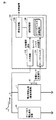
まず、本実施の形態に係る部分放電検出装置の装置構成の一例について説明する。図3は、本実施の形態に係る部分放電検出装置100の装置構成例を示す模式図である。図3を参照して、部分放電検出装置100は、電力用変圧器1(検査対象物)の充電部にインパルス電圧発生装置10からインパルス電圧を印加することで発生する部分放電を検出する。具体的には、部分放電検出装置100は、検査対象物の外面に装着される音響センサ30と、入力回路102と、ローパスフィルタ104と、波形記録部106と、信号処理部108とを含む。
[B. Device configuration]
First, an example of the device configuration of the partial discharge detection device according to the present embodiment will be described. FIG. 3 is a schematic diagram illustrating a device configuration example of the partial
音響センサ30は、典型的には、電力用変圧器1の高電圧充電部を収納する金属筐体(タンク)の外面に装着される。音響センサ30は、物質の機械的な動きによって発生する弾性波(ストレスウェーブ)をAE(Acoustic Emission)法によって検出し、その検出結果を電気信号として出力する。本実施の形態においては、検査対象物の内部で発生した部分放電に起因する音響信号を音響センサ30によって検出する。以下の説明においては、音響センサ30から出力される生の電気信号を「音響センサ測定信号」とも称す。
The
入力回路102は、インパルス電圧発生装置10と電力用変圧器1とを電気的に接続する印加ケーブル6に電気的に接続され、電力用変圧器1に印加される電圧の時間波形(以下、「印加電圧波形」とも称す。)を波形記録部106に入力可能な電圧値にまで降圧する分圧回路などを含む。すなわち、入力回路102からは、電力用変圧器1に印加される印加電圧波形を示す信号が出力される。入力回路102は、後述するような、インパルス電圧の電力用変圧器1(検査対象物)への印加が開始されたタイミング(以下、「インパルス電圧印加開始時刻」とも称す。)を取得する機能の一部を実現する。
The input circuit 102 is electrically connected to an
ローパスフィルタ104には、音響センサ30からの音響センサ測定信号が入力され、ローパスフィルタ104を通過後の音響信号(以下、「ローパスフィルタ処理信号」とも称す。)を波形記録部106へ出力する。後述するように、ローパスフィルタ104は、音響センサ30によって取得される音響センサ測定信号に重畳している電磁ノイズを除去する。
An acoustic sensor measurement signal from the
波形記録部106は、入力回路102からの印加電圧波形、および、ローパスフィルタ104からのローパスフィルタ処理信号の時間波形を記録する。波形記録部106は、複数回のインパルス電圧の印加それぞれについて、時間波形を記録できるように構成されている。なお、波形記録部106としては、一般的なオシロスコープを採用してもよい。
The
信号処理部108は、インパルス電圧印加開始時刻を取得するとともに、後述するようなノイズ除去処理を行った上で、電力用変圧器1(検査対象物)の内部での部分放電の発生の有無を判断する。信号処理部108は、この部分放電の検出の有無を診断結果として出力する。なお、後述するような信号処理部108における処理の一部または全部を作業者が行うようにしてもよい。つまり、波形記録部106に記録される信号波形を用いて部分放電の発生の有無を判断する処理については、完全に自動化、一部を自動化、すべてを手動化のいずれで実現してもよい。
The
[C.ノイズ除去処理の概要]
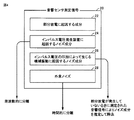
次に、本実施の形態に係る部分放電検出方法におけるノイズ除去処理の概要について説明する。図4は、本実施の形態に係る部分放電検出装置100において実行される音響センサ測定信号に対するノイズ除去処理の概要を説明するための図である。
[C. Overview of noise reduction processing]
Next, an outline of noise removal processing in the partial discharge detection method according to the present embodiment will be described. FIG. 4 is a diagram for explaining the outline of the noise removal process for the acoustic sensor measurement signal executed in the partial
図4を参照して、電気機器の雷インパルス耐電圧試験時において、音響センサ30によって取得される音響センサ測定信号20には、本来の検出対象である部分放電に起因する成分22と、インパルス電圧発生装置10に起因するノイズ成分24と、インパルス電圧の印加によって生じる機械振動に起因するノイズ成分26と、外来ノイズ成分28とが含まれる。
Referring to FIG. 4, during the lightning impulse withstand voltage test of the electrical equipment, the acoustic
(1) インパルス電圧発生装置10に起因するノイズ成分24の分離
本実施の形態に係る部分放電検出方法では、インパルス電圧発生装置10から放射される電磁ノイズの影響(ノイズ成分24)を周波数的に分離することで、部分放電に起因する成分22が電磁ノイズに埋没することを回避する。より具体的には、音響センサ測定信号20にローパスフィルタ104(図3参照)を適用することでローパスフィルタ処理信号が生成され、このローパスフィルタ処理信号においては、ノイズ成分24が実質的に除去されることになる。
(1) Separation of
(2) 機械振動に起因するノイズ成分26の除去
機械振動に起因するノイズ成分26については、部分放電が発生していないときに測定された音響信号によりノイズ成分26を推定して除去する。より具体的には、部分放電を確実に発生させない波高値の低いインパルス電圧を印加したときに現れる機械振動波形(ノイズ成分26)を利用して、部分放電が発生し得る波高値の高いインパルス電圧を印加したときに現れる機械振動成分を推定し除去することで、部分放電に起因する成分22のみを抽出する。
(2) Removal of
一般的に、電力用変圧器1のような大容量の電力機器に対して雷インパルス耐電圧試験を行う場合には、標準規格で規定された試験電圧をいきなり印加することはなく、まず規定どおりの波頭長および波尾長を有するインパルス電圧が出力されているかが確認される。このときの確認作業としては、電力用変圧器1の内部で部分放電を確実に発生させない波高値の低いインパルス電圧が数回出力される。波高値の低いインパルス電圧を印加した場合であっても電力用変圧器1のコイル3には充電電流が流れるため、検査対象物自体に機械振動が生じ、音響センサ30では、これに伴う機械振動に起因するノイズ成分26が検出される。
In general, when conducting a lightning impulse withstand voltage test on a large-capacity power device such as the
機械振動に起因するノイズ成分26は、検査対象物に印加するインパルス電圧の波高値を変化させても周期は全く同一であり、振幅値のみが変化すると考えられる。本願発明者らは、機械振動に起因するノイズ成分26の振幅値が、各巻線のコイル3に流れる充電電流の二乗に比例する、すなわち印加電圧の二乗に比例することを実験的に明らかにした。
It is considered that the
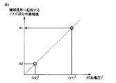
図5は、本実施の形態に係る印加されるインパルス電圧の印加電圧(波高値)とインパルス電圧の印加によって生じる機械振動に起因するノイズ成分の振幅値との関係を示す図である。図5に示すように、本願発明者らは、音響センサ測定信号に含まれる機械振動に起因するノイズ成分26の振幅値は、インパルス電圧の波高値の二乗に比例することを見出した。印加されるインパルス電圧の波高値と機械振動に起因するノイズ成分の振幅値との関係を利用して、まず、部分放電が発生しない低いインパルス電圧(波高値V2)の印加時に音響センサ30によって取得される検出信号(音響センサ測定信号20)に現れる機械振動に起因するノイズ成分の時間波形f2(t)を取得する。
FIG. 5 is a diagram showing the relationship between the applied voltage (crest value) of the applied impulse voltage according to the present embodiment and the amplitude value of the noise component caused by the mechanical vibration caused by the application of the impulse voltage. As shown in FIG. 5, the inventors of the present application have found that the amplitude value of the
次に、雷インパルス耐電圧試験の標準規格に準拠した高いインパルス電圧(波高値V1)を印加したとする。低いインパルス電圧(波高値V2)の印加時に取得された機械振動に起因するノイズ成分の時間波形の振幅値に対して、高電圧印加時の波高値V1を低電圧印加時の波高値V2で除した数値の二乗を乗じることで、高いインパルス電圧を印加したときに生じる機械振動に起因するノイズ成分26を決定できる。つまり、高いインパルス電圧(波高値V1)の印加時に音響センサ30によって取得される検出信号(音響センサ測定信号20)に現れる機械振動に起因するノイズ成分の時間波形f1(t)は、以下のような式で算出できる。
Next, it is assumed that a high impulse voltage (crest value V1) conforming to the standard of the lightning impulse withstand voltage test is applied. With respect to the amplitude value of the time waveform of the noise component resulting from mechanical vibration obtained when a low impulse voltage (peak value V2) is applied, the peak value V1 when a high voltage is applied is divided by the peak value V2 when a low voltage is applied. By multiplying the square of the numerical value, the
時間波形f1(t)=時間波形f2(t)×(V1/V2)2
高電圧印加時に取得されるローパスフィルタ処理信号とこの高電圧印加時の機械振動に起因するノイズ成分の時間波形f1(t)との差分を取ることで、機械振動に起因するノイズ成分26を除去することができる。このような手法を採用することで、インパルス電圧を印加することで検査対象物に充電電流が流れることで生じる検査対象物自体の機械振動の影響を除去することができる。すなわち、時間波形f2(t)は、ノイズ成分26の時間波形f1(t)を決定するための参照信号に相当する。
Time waveform f1 (t) = time waveform f2 (t) × (V1 / V2) 2
By taking the difference between the low-pass filter processing signal acquired when a high voltage is applied and the time waveform f1 (t) of the noise component caused by the mechanical vibration when the high voltage is applied, the
(3) 外来ノイズ成分28の除去
外来ノイズ成分28としては、例えば、雷インパルス耐電圧試験中に電力用変圧器1のタンク4に異物が衝突することによる衝撃音や、タンク4外で発生する音による弾性波等などに起因して生じ得る。このような外来ノイズ成分28については、部分放電に伴う弾性波信号が音響センサ30まで到達するのに要する最小時間と最大時間とを予め予測しておき、この最小時間から最大時間までの間に音響センサ30に到来する弾性波信号のみを有効な音響信号として取得することで、時間的に分離する。
(3) Removal of
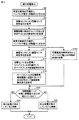
[D.具体的な処理手順]
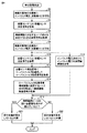
次に、本実施の形態に係る部分放電検出方法の具体的な処理手順について、図6および図7を参照しつつ説明する。図6は本実施の形態に係る部分放電検出方法の処理手順を示すフローチャートである。図7は、本実施の形態に係る部分放電検出方法によって取得される時間波形の一例である。
[D. Specific processing procedure]
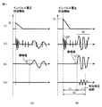
Next, a specific processing procedure of the partial discharge detection method according to the present embodiment will be described with reference to FIGS. FIG. 6 is a flowchart showing a processing procedure of the partial discharge detection method according to the present embodiment. FIG. 7 is an example of a time waveform acquired by the partial discharge detection method according to the present embodiment.
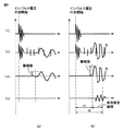
図7(a)には、部分放電が発生しない低いインパルス電圧(波高値V2)を電力用変圧器1の充電部に印加した場合に測定される時間波形を示し、図7(b)には、高いインパルス電圧(波高値V1)を電力用変圧器1の充電部に印加して、実際に部分放電が発生した場合に測定される時間波形を示す。図7において、(i)には、インパルス電圧発生装置10から検査対象物である電力用変圧器1の充電部に印加されるインパルス電圧の時間波形(印加電圧波形)の一例を示し、(ii)には、音響センサ30によって取得される音響センサ測定信号20の時間波形の一例を示し、(iii)には、ローパスフィルタ104を通過後の音響信号(ローパスフィルタ処理信号)の時間波形の一例を示し、(iv)には、ローパスフィルタ処理信号から検査対象物である電力用変圧器1の機械振動に起因するノイズ成分26を除去した後の時間波形の一例を示す。
FIG. 7A shows a time waveform measured when a low impulse voltage (crest value V2) at which partial discharge does not occur is applied to the charging part of the
図6を参照して、まず、インパルス電圧の印加によって生じる機械振動に起因するノイズ成分26を除去するための時間波形f2(t)が予め取得される(ステップS2〜S6)。但し、機械振動に起因するノイズ成分26を除去するための時間波形を取得する処理については、後述のステップS8〜S22の処理とは独立して行ってもよい。例えば、検査対象物が複数の電気機器である場合に、それらの間で電気的特性および機械的特性のバラツキが少ないときには、ある電気機器について、機械振動に起因するノイズ成分26を除去するための時間波形を予め取得しておき、これを複数の電気機器について共通的に用いるようにしてもよい。
Referring to FIG. 6, first, a time waveform f2 (t) for removing
より具体的には、検査対象物である電力用変圧器1の充電部にインパルス電圧(波高値V2:第2のインパルス電圧)が印加される(ステップS2)。つまり、電力用変圧器1の内部で部分放電を確実に発生させない波高値の低いインパルス電圧が印加される。ステップS2では、図7(a)の(i)に示すようなインパルス電圧が印加される。
More specifically, an impulse voltage (crest value V2: second impulse voltage) is applied to the charging part of the
続いて、検査対象物の外面に装着される音響センサ30により、インパルス電圧の印加に伴って発生する音響センサ測定信号20(第4の測定信号)が取得される(ステップS4)。音響センサ30は、典型的にはタンク4の外面に装着される。ステップS4では、図7(a)の(ii)に示すような音響センサ測定信号20が取得される。
Subsequently, the acoustic sensor measurement signal 20 (fourth measurement signal) generated with the application of the impulse voltage is acquired by the
さらに、取得された音響センサ測定信号20にローパスフィルタ104を適用することで、部分放電が発生し得る高いインパルス電圧(波高値V1)の印加によって生じる機械振動に起因するノイズ成分26(ノイズ成分)を決定するための時間波形f2(t)(参照信号)が取得される(ステップS6)。つまり、部分放電が発生しない低いインパルス電圧(波高値V2)の印加時に音響センサ30によって取得される検出信号(音響センサ測定信号20)に現れる機械振動に起因するノイズ成分の時間波形f2(t)が取得される。ステップS6では、図7(a)の(iii)に示すようなローパスフィルタ処理信号が時間波形f2(t)として取得される。ローパスフィルタ104の詳細については、後述する。
Furthermore, by applying the low-pass filter 104 to the acquired acoustic
なお、図7(a)の(iv)の時間波形に示すように、電力用変圧器1の内部で部分放電が発生していなければ、ローパスフィルタ処理信号から電力用変圧器1の機械振動に起因するノイズ成分26を除去すると、実質的に何らの成分も残らない。
As shown in the time waveform of (iv) in FIG. 7A, if partial discharge does not occur inside the
以上のステップによって、機械振動に起因するノイズ成分26を音響センサ測定信号20から除去するための参照信号が用意される。そして、通常の雷インパルス耐電圧試験が実行される。
Through the above steps, a reference signal for removing the
まず、雷インパルス耐電圧試験時に際し、検査対象物である電力用変圧器1の充電部に、標準規格を満たすインパルス電圧(波高値V1:第1のインパルス電圧)が印加される(ステップS8)。すなわち、検査対象物である電力用変圧器1の高電圧充電部を内部に収納した金属筐体(タンク)の外面に音響センサ30を装着し、インパルス電圧を検査対象物に印加する処理が実行される。このとき、電力用変圧器1の内部で部分放電が発生し得る高いインパルス電圧が印加される。一般的な高電圧機器の雷インパルス耐電圧試験時においては、標準規格で、印加されるインパルス電圧波形の波頭長および波尾長が定められており、また電気機器の定格電圧や容量に応じて波高値も定められている。ステップS8では、図7(b)の(i)に示すようなインパルス電圧が印加される。
First, during the lightning impulse withstand voltage test, an impulse voltage (crest value V1: first impulse voltage) satisfying the standard is applied to the charging part of the
すると、インパルス電圧の印加が開始されたタイミングが取得される(ステップS16)。すなわち、インパルス電圧波形を波形記録部106に取込み、インパルス電圧印加開始時刻を取得する処理が実行される。このタイミングの取得方法としては、図7(b)の(i)に示すようなインパルス電圧波形を波形記録部106に取込み、その振幅値が予め定められたしきい値を超えたタイミングをインパルス電圧印加開始時刻として決定できる。なお、雷インパルス耐電圧試験時におけるインパルス電圧は高電圧であるため、分圧回路などを含む入力回路102を介して波形記録部106に取込まれる。
Then, the timing when the application of the impulse voltage is started is acquired (step S16). That is, the process of acquiring the impulse voltage waveform in the
ステップS16と並行して、検査対象物である電力用変圧器1の外面に装着された音響センサ30によって音響センサ測定信号20(第1の測定信号)が取得される(ステップS10)。すなわち、インパルス電圧波形を波形記録部106に取込む処理と並行して、電力用変圧器1のタンク4の外面に装着した音響センサ30により、インパルス電圧の印加に伴う音響センサ測定信号20を取得する処理が実行される。ステップS10では、図7(b)の(ii)に示すような音響センサ測定信号20が取得される。
In parallel with step S16, the acoustic sensor measurement signal 20 (first measurement signal) is acquired by the
続いて、音響センサ測定信号20(第1の測定信号)にローパスフィルタ104を適用することでローパスフィルタ処理信号(第2の測定信号)が取得される(ステップS12)。すなわち、音響センサ30で検出される音響センサ測定信号20に重畳する電磁ノイズを、ローパスフィルタ104を介して除去する処理が実行される。ステップS12では、図7(b)の(iii)に示すようなローパスフィルタ処理信号が取得される。
Subsequently, the low-pass filter processing signal (second measurement signal) is obtained by applying the low-pass filter 104 to the acoustic sensor measurement signal 20 (first measurement signal) (step S12). That is, the process of removing the electromagnetic noise superimposed on the acoustic
上述したように、インパルス電圧発生装置10は、装置内に設置された球ギャップ14間に火花放電を発生させることで、要求されたインパルス電圧を出力する。球ギャップ14間の火花放電が発する非常に強い電磁ノイズが、部分放電の検出を困難にしている大きな要因である。一方で、電磁ノイズが集中的に継続する時間は、高々数10マイクロ秒程度である(図7(b)の(ii)に示す時間範囲52)。電力用変圧器1のタンク4内の絶縁油中における音響信号の伝播速度は、一般に毎秒1500メートルである。タンク4のサイズにも依存するが、タンク4内に収納されたコイル3から発せられた音響信号が音響センサ30に到達するためには、およそ数100マイクロ秒から数ミリ秒の時間を要する。すなわち、インパルス電圧の印加に伴って発生する音響信号が音響センサ30によって取得される時間範囲(図7(b)の(ii)に示す時間範囲54)は、インパルス電圧発生装置10から放射される非常に強い電磁ノイズの大半が減衰した後である。これが部分放電の検出手段として、音響センサ30を用いることの大きな利点である。
As described above, the
しかしながら、大半の電磁ノイズが減衰した後であっても、音響センサ測定信号20には依然として電磁ノイズ成分が重畳した波形となっている。そこで、取得された音響センサ測定信号20をローパスフィルタ104に通過させることで、電磁ノイズの成分(インパルス電圧発生装置10に起因するノイズ成分24)を音響センサ測定信号20から除去する。図3に示す部分放電検出装置100のローパスフィルタ104は、音響センサ30で検出された音響センサ測定信号20(第1の測定信号)にローパスフィルタを適用することでローパスフィルタ処理信号(第2の測定信号)を出力する信号処理部に相当する。なお、ローパスフィルタ104の機能を、波形記録部106および/または信号処理部108でのデジタル信号処理によって実現してもよい。
However, even after most of the electromagnetic noise is attenuated, the acoustic
ローパスフィルタ104としては、本来の音響信号と電磁ノイズとを周波数的に分離できるカットオフ周波数特性を有するものが選定される。インパルス電圧発生装置10の球ギャップ14間の火花放電により放射される電磁ノイズは、数100MHzオーダの成分が強い一方で、音響信号は、数10〜数100kHzである。例えば、カットオフ周波数が1MHz程度のローパスフィルタ104を採用することで、音響センサ測定信号20に重畳する電磁ノイズの成分を除去し、検出対象の音響信号の成分のみを通過させることができる。
As the low-pass filter 104, a filter having a cutoff frequency characteristic capable of separating the original acoustic signal and electromagnetic noise in terms of frequency is selected. The electromagnetic noise radiated by the spark discharge between the
以上のステップにより、電磁ノイズを除去することでインパルス電圧の印加に伴って生じる音響信号の主成分を取得することができる。しかしこの時点では、電力用変圧器1の内部における部分放電の発生の有無にかかわらず、充電電流が瞬間的に流れることによって生じる電力用変圧器1のコイル3の機械振動に起因するノイズ成分26がローパスフィルタ処理信号に含まれている。そこで、次のステップでは、ローパスフィルタ処理信号に含まれる機械振動に起因するノイズ成分26を除去する処理が実行される。
Through the above steps, the main component of the acoustic signal generated by applying the impulse voltage can be acquired by removing electromagnetic noise. However, at this point, the
すなわち、ローパスフィルタ処理信号(第2の測定信号)から検査対象物である電力用変圧器1の機械振動に起因するノイズ成分26を除去することで機械振動除去信号(第3の測定信号)が取得される(ステップS14)。ステップS14では、図7(b)の(iv)に示すような機械振動除去信号が取得される。すなわち、予め取得しておいた、部分放電が発生しない低電圧印加時に音響センサ30に現れる検査対象物の機械振動成分をもとに、高電圧印加時の音響信号から機械振動成分が除去される。
That is, the mechanical vibration removal signal (third measurement signal) is obtained by removing the
より具体的には、上述のステップS6の実行によって予め取得された時間波形f2(t)(参照信号)の振幅に(波高値V1/波高値V2)2を乗じることで、ノイズ成分としての時間波形を算出し、これをローパスフィルタ処理信号から差し引くことで、機械振動除去信号が取得される。このように、インパルス電圧の印加によって生じる機械振動に起因するノイズ成分26は、検査対象物である電力用変圧器1で部分放電を発生させない、標準規格を満たす波高値V1のインパルス電圧(第1のインパルス電圧)より低い波高値V2のインパルス電圧(第2のインパルス電圧)を電力用変圧器1(検査対象物)の充電部に印加したときに、音響センサ30によって取得される音響センサ測定信号20(第4の測定信号)に基づいて決定される。
More specifically, the time as a noise component is obtained by multiplying the amplitude of the time waveform f2 (t) (reference signal) acquired in advance by the execution of the above-described step S6 by (wave height value V1 / wave height value V2) 2. A mechanical vibration removal signal is obtained by calculating a waveform and subtracting this from the low-pass filter processing signal. As described above, the
以上のステップにより、音響センサ30によって取得される音響センサ測定信号から、インパルス電圧発生装置10から放射される電磁ノイズによる影響(ノイズ成分24)、および、電力用変圧器1のコイル3の機械振動に起因する影響(ノイズ成分26)を除去することができる。但し、音響センサ30を用いて取得した音響センサ測定信号には、ここで挙げた部分放電信号由来以外の外来ノイズが重畳している可能性が残っている。例えば、雷インパルス耐電圧試験中に電力用変圧器1のタンク4に異物が衝突することによる衝撃音や、タンク4外で発生する音による弾性波等がタンク4の外面に装着した音響センサ30で外来ノイズとして検出されることなどが考えられる。そこで、本実施の形態に係る部分放電検出方法の最後のステップとして、外来ノイズの影響を除去する処理が実行される。
From the acoustic sensor measurement signal acquired by the
電力用変圧器1のタンク4内の絶縁油中における音響信号の伝播速度は、一般に毎秒1500メートルである。この伝播速度と予め把握してある電力用変圧器1の構造物における高電圧充電部と音響センサ30との距離に基づいて、インパルス電圧印加開始時刻から、部分放電に伴う弾性波信号が音響センサ30まで到達するまでの時間差をある時間範囲の中で予測しておくことができる。すなわち、部分放電に伴う弾性波信号が音響センサ30まで到達するのに要する最小時間と最大時間とを予め予測しておき、この最小時間から最大時間までの間に音響センサ30に到来する弾性波信号のみを有効な音響信号として取得する。
The propagation speed of the acoustic signal in the insulating oil in the
より具体的には、電力用変圧器1の構造物における高電圧充電部から音響センサ30の装着位置までの最短距離を、絶縁油中の音響信号の伝播速度で除した時間をt1とし、電力用変圧器1の構造物における高電圧充電部と音響センサ30までの最長距離を、絶縁油中の音響信号の伝播速度で除した時間をt2とした場合、インパルス電圧印加開始時刻を基準として、電力用変圧器1の構造物における高電圧充電部と音響センサ30の装着位置との間の距離によって定まる所定の時間範囲t1〜t2の間に現れる音響信号成分のみを用いて、部分放電の発生の有無を判断することで、外来ノイズを部分放電の発生と誤診する可能性を実質的に無くすことができる。つまり、高電圧充電部と音響センサ30との位置関係で決まる所定の時間範囲t1〜t2の間に音響信号成分が現れているか否かが判断される(ステップS18)。そして、所定の時間範囲t1〜t2の間に音響信号成分が現れている場合(ステップS18においてYESの場合)には、検査対象物である電力用変圧器1の内部において部分放電が発生していると判断される(ステップS20)。これに対して、所定の時間範囲t1〜t2の間に音響信号成分が現れていない場合(ステップS18においてNOの場合)には、検査対象物である電力用変圧器1の内部において部分放電が発生していないと判断される(ステップS22)。
More specifically, the time obtained by dividing the shortest distance from the high voltage charging part in the structure of the
このように、取得されたインパルス電圧の印加が開始されたタイミングを基準として、検査対象物である電力用変圧器1における充電部と音響センサ30との位置関係に応じて定まる有効測定期間内に現れる、機械振動除去信号(第3の測定信号)の時間波形に基づいて、検査対象物での部分放電の発生の有無が判断される。つまり、機械振動成分を除去した音響信号波形のうち、インパルス電圧印加開始時刻を基準とし、検査対象物の高電圧充電部と音響センサ30の装着位置とによって定まる所定の時間範囲内に現れる音響信号を部分放電であると判断する処理が実行される。
Thus, within the effective measurement period that is determined according to the positional relationship between the charging unit and the
以上のステップにより、電力用変圧器1の雷インパルス耐電圧試験時においても、インパルス電圧発生装置10に起因するノイズ、電力用変圧器1のコイル3の機械振動に起因するノイズ、および他の外来ノイズの影響を回避し、電力用変圧器1の内部で発生する部分放電を適切に検出できる。
Through the above steps, even during the lightning impulse withstand voltage test of the
図3に示す部分放電検出装置100の信号処理部108は、上述のステップS16に示される、インパルス電圧の印加が開始されたタイミングを取得する機能を含む。また、信号処理部108は、上述のステップS14に示される、ローパスフィルタ処理信号(第2の測定信号)から検査対象物である電力用変圧器1の機械振動に起因するノイズ成分26を除去することで機械振動除去信号(第3の測定信号)を取得する機能と、ステップS20に示される、取得されたタイミングを基準として、検査対象物である電力用変圧器1における充電部と音響センサ30との位置関係に応じて定まる有効測定期間内に現れる、機械振動除去信号(第3の測定信号)の時間波形に基づいて、検査対象物での部分放電の発生の有無を判断する機能とを有する。
The
このような信号処理部108を有する部分放電検出装置100を用いることで、上述の処理手順を実行することができる。これによって、インパルス電圧発生装置10を用いて検査対象物である電力用変圧器1にインパルス電圧を印加した場合に、電力用変圧器1の内部で発生する部分放電を検出することができる。
By using the partial
また、本実施の形態に係る部分放電検出方法によれば、インパルス電圧発生装置10から放射される電磁ノイズによる影響、および、インパルス電圧を印加することで検査対象物に充電電流が流れることで生じる検査対象物自体の機械振動の影響、を除去することができる。これによって、雷インパルス耐電圧試験時において機器内部で発生する部分放電を適切に検出することができる。
In addition, according to the partial discharge detection method according to the present embodiment, it is caused by the influence of electromagnetic noise radiated from the
[E.インパルス電圧の印加が開始されたタイミング取得についての第1変形例]
上述の実施の形態においては、インパルス電圧の電力用変圧器1(検査対象物)への印加が開始されたタイミング(インパルス電圧印加開始時刻)を取得する手段として、電力用変圧器1に印加される電圧の時間波形(印加電圧波形)を取込み、この時間的変化に基づいて、インパルス電圧印加開始時刻を取得する方法について例示した。このような手法に代えて、電磁波センサを用いて、電圧印加開始時刻を取得してもよい。以下、電磁波センサを用いて電圧印加開始時刻を取得する変形例について例示する。
[E. First modified example of timing acquisition at which application of impulse voltage is started]
In the above-described embodiment, it is applied to the
図8は本実施の形態の第1変形例に係る部分放電検出方法の処理手順を示すフローチャートである。図9は、本実施の形態の第1変形例に係る部分放電検出方法によって取得される時間波形の一例である。図9(a)には、部分放電が発生しない低いインパルス電圧(波高値V2)を電力用変圧器1の充電部に印加した場合に測定される時間波形を示し、図9(b)には、高いインパルス電圧(波高値V1)を電力用変圧器1の充電部に印加して、実際に部分放電が発生した場合に測定される時間波形を示す。図9において、(i)には、インパルス電圧発生装置10から放射される電磁ノイズを電磁波センサで取得した時間波形の一例を示す。その他の(ii)〜(iv)については、図7の(ii)〜(iv)と同様である。
FIG. 8 is a flowchart showing a processing procedure of the partial discharge detection method according to the first modification of the present embodiment. FIG. 9 is an example of a time waveform acquired by the partial discharge detection method according to the first modification of the present embodiment. FIG. 9A shows a time waveform measured when a low impulse voltage (crest value V2) at which partial discharge does not occur is applied to the charging part of the
本変形例においては、図3に示す部分放電検出装置100において、入力回路102に代えて、電磁波センサが設けられている。電磁波センサとしては、典型的には、電磁波アンテナが用いられるが、インパルス電圧発生装置10が放射する電磁ノイズを検出できるデバイスであれば、どのようなものを採用してもよい。
In this modification, an electromagnetic wave sensor is provided in place of the input circuit 102 in the partial
上述したように、インパルス電圧発生装置10は、動作原理として球ギャップ14間の火花放電を利用しており、インパルス電圧の出力と同時に非常に強い電磁ノイズが放射される。この電磁ノイズは、部分放電を検出する上では障害となるものであるが、原理上、インパルス電圧の印加と同じタイミングで放射されるものであるので、インパルス電圧印加開始時刻を取得する際に利用できる。特に、電磁ノイズに含まれる周波数成分としては数100MHz程度の周波数帯域成分が多く、電磁波センサを用いて電磁ノイズの波形を取得すると、その検出信号における立ち上がりが非常に早いという特徴がある(図9(a)および(b)の(i)に示す電磁波センサの検出結果)。
As described above, the
したがって、電磁波センサを用いてインパルス電圧印加開始時刻を取得するという手法を採用することにより、インパルス電圧印加開始時刻をより正確に取得することができる。また、電力用変圧器1に印加される電圧の時間波形(印加電圧波形)を取込む場合には、比較的高圧の信号が入力されるので、入力回路102の絶縁耐性を考慮しなければならないが、電磁波センサの場合であれば、このような点を考慮しなくてもよいという利点もある。
Therefore, by adopting a method of acquiring the impulse voltage application start time using an electromagnetic wave sensor, the impulse voltage application start time can be acquired more accurately. In addition, when a time waveform (applied voltage waveform) of a voltage applied to the
図8に示す本変形例に係る処理手順は、図6に示す本実施の形態に係る処理手順に比較して、ステップS16に代えて、ステップS16Aが採用されている。ステップS16Aにおいては、インパルス電圧発生装置10から放射される電磁ノイズの時間波形を、電磁波センサを用いて波形記録部106に取込み、インパルス電圧印加開始時刻を取得する処理が実行される。このタイミングの取得方法としては、その振幅値が予め定められたしきい値を超えたタイミングをインパルス電圧印加開始時刻として決定できる。つまり、インパルス電圧の印加が開始されたタイミングを取得するステップは、インパルス電圧の印加によって生じる電磁波の変化を電磁波センサによって検出するステップを含む。
The processing procedure according to this modification shown in FIG. 8 employs step S16A instead of step S16, as compared to the processing procedure according to the present embodiment shown in FIG. In step S <b> 16 </ b> A, a process of acquiring a time waveform of electromagnetic noise radiated from the
本変形例においては、インパルス電圧印加開始時刻を取得するため、電磁波センサが用いられる。このような構成を採用することで、高周波成分を含み、立ち上がりの早い電磁波を利用することができ、インパルス電圧印加開始時刻をより明確に把握することができる。 In this modification, an electromagnetic wave sensor is used to acquire the impulse voltage application start time. By adopting such a configuration, it is possible to use an electromagnetic wave that includes a high-frequency component and has a fast rise, and can more clearly grasp the impulse voltage application start time.
[F.インパルス電圧の印加が開始されたタイミング取得についての第2変形例]
上述の実施の形態においては、インパルス電圧の電力用変圧器1(検査対象物)への印加が開始されたタイミング(インパルス電圧印加開始時刻)を取得する手段として、電力用変圧器1に印加される電圧の時間波形(印加電圧波形)を取込み、この時間的変化に基づいて、インパルス電圧印加開始時刻を取得する方法について例示した。このような手法に代えて、電流センサを用いて、電圧印加開始時刻を取得してもよい。すなわち、検査対象物である電力用変圧器1にインパルス電圧発生装置10からインパルス電圧を印加すると、電力用変圧器1の静電容量を介して充電電流が流れる。電流センサを用いて、この充電電流が検出される。以下、電流センサを用いて電圧印加開始時刻を取得する変形例について例示する。
[F. Second Modified Example Regarding Timing Acquisition at which Impulse Voltage Application is Started]
In the above-described embodiment, it is applied to the
図10は、本実施の形態の第2変形例に係る部分放電検出方法の処理手順を示すフローチャートである。図11は、本実施の形態の第2変形例に係る部分放電検出方法によって取得される時間波形の一例である。図11(a)には、部分放電が発生しない低いインパルス電圧(波高値V2)を電力用変圧器1の充電部に印加した場合に測定される時間波形を示し、図11(b)には、高いインパルス電圧(波高値V1)を電力用変圧器1の充電部に印加して、実際に部分放電が発生した場合に測定される時間波形を示す。図11において、(i)には、インパルス電圧発生装置10からインパルス電圧が印加された際に、電力用変圧器1の静電容量を介して流れる充電電流を電流センサで取得した時間波形の一例を示す。その他の(ii)〜(iv)については、図7および図9の(ii)〜(iv)と同様である。
FIG. 10 is a flowchart showing a processing procedure of the partial discharge detection method according to the second modification of the present embodiment. FIG. 11 is an example of a time waveform acquired by the partial discharge detection method according to the second modification of the present embodiment. FIG. 11A shows a time waveform measured when a low impulse voltage (crest value V2) at which partial discharge does not occur is applied to the charging portion of the
本変形例においては、図3に示す部分放電検出装置100において、入力回路102に代えて、電流センサが設けられている。
In this modification, a current sensor is provided in place of the input circuit 102 in the partial
上述したように、インパルス電圧発生装置10からインパルス電圧が電力用変圧器1に印加されると、電力用変圧器1の静電容量を介して充電電流が流れる。インパルス電圧の立ち上がり時間は1マイクロ秒程度と短いため、充電電流の周波数成分も高くなるため、電流センサを用いてインパルス電圧印加開始時刻を取得するという処理により、電圧印加開始時刻を明確に取得することが可能となる(図11(a)および(b)の(i)に示す電磁波センサの検出結果)。
As described above, when the impulse voltage is applied from the
したがって、電力用変圧器1の静電容量を介して流れる充電電流を、電流センサを用いて測定することで、インパルス電圧印加開始時刻を取得するという手法を採用することにより、インパルス電圧印加開始時刻をより正確に取得することができる。
Therefore, by adopting a method of acquiring the impulse voltage application start time by measuring the charging current flowing through the capacitance of the
図10に示す本変形例に係る処理手順は、図6に示す本実施の形態に係る処理手順に比較して、ステップS16に代えて、ステップS16Bが採用されている。ステップS16Bにおいては、インパルス電圧発生装置10からインパルス電圧が印加されることで電力用変圧器1の静電容量を介して流れる充電電流の時間波形を、電流センサを用いて波形記録部106に取込み、インパルス電圧印加開始時刻を取得する処理が実行される。このタイミングの取得方法としては、その振幅値が予め定められたしきい値を超えたタイミングをインパルス電圧印加開始時刻として決定できる。つまり、インパルス電圧の印加が開始されたタイミングを取得するステップは、インパルス電圧の印加によって生じる電流の変化を電流センサによって検出するステップを含む。
The processing procedure according to this modification shown in FIG. 10 employs step S16B instead of step S16 as compared to the processing procedure according to the present embodiment shown in FIG. In step S16B, the time waveform of the charging current flowing through the capacitance of the
本変形例においては、インパルス電圧印加開始時刻を取得するため、電流センサが用いられる。このような構成を採用することで、高周波成分を含み、立ち上がりの早い電流信号を利用することができ、インパルス電圧印加開始時刻をより明確に把握することができる。 In this modification, a current sensor is used to acquire the impulse voltage application start time. By adopting such a configuration, it is possible to use a current signal that includes a high-frequency component and has a fast rise, and can more clearly grasp the impulse voltage application start time.
[G.部分放電が発生している位置の標定機能(第3変形例)]
上述の実施の形態およびその変形例の説明においては、基本的な構成として、1つの音響センサ30を用いて、検査対象物の内部で発生する部分放電を検出する実施形態について説明したが、複数の音響センサ30を検査対象物の外面に装着し、部分放電が発生している位置を標定(特定)してもよい。
[G. Positioning function of position where partial discharge is occurring (third modification)]
In the description of the above-described embodiment and its modified examples, the embodiment has been described in which the partial discharge generated inside the inspection object is detected using one
3次元構造をもつタンク4の内部で発生する部分放電の位置を一意に標定するためには、原理的に4つの音響センサ30が必要である。但し、5つ以上の音響センサ30で同時計測を行うことで、部分放電の位置標定の精度を高めることができる。以下、電力用変圧器1の高電圧充電部を収納するタンク4の外面に、4つ以上の音響センサ30が装着されているとして説明を行う。また、図3に示す部分放電検出装置100においては、装着された音響センサ30の数と同数のローパスフィルタ104が設けられており、また波形記録部106は、それぞれのローパスフィルタ104から出力されるローパスフィルタ処理信号を記録できるように構成されているとする。その他の部位については、上述した構成と同様であるので、詳細な説明は繰返さない。
In order to uniquely determine the position of the partial discharge generated inside the
タンク4の外面に複数の音響センサ30を装着した場合にも、電力用変圧器1にインパルス電圧を印加する、音響センサ30の各々において電力用変圧器1のコイル3の機械振動に起因するノイズ成分が検出される。但し、一般的には、電力用変圧器1の構造物における高電圧充電部と各音響センサ30との距離が互いに異なっていたり、各音響センサ30から高電圧充電部への角度が異なっていたりしているため、音響センサ30の各々では互いに異なった固有の機械振動波形が検出される。
Even when a plurality of
このような場合であっても、音響センサ30の各々に現れる機械振動に起因するノイズ成分26は、検査対象物に印加するインパルス電圧の波高値を変化させても周期は全く同一であり、振幅値のみが変化する。また、機械振動に起因するノイズ成分26の振幅値は、各巻線のコイル3に流れる充電電流の二乗に比例する、すなわち印加電圧の二乗に比例する。このような特徴については、音響センサ30が一つの場合と変わらない。但し、振幅値の変化に係る比例定数は、音響センサ30毎に異なったものとなる。
Even in such a case, the
このような特徴を考慮すると、部分放電を確実に発生させない波高値の低いインパルス電圧を印加したときに現れる機械振動波形(ノイズ成分26)を音響センサ30毎にそれぞれ測定しておき、実際に、標準規格で定められた波高値をもつインパルス波形を印加した際に音響センサ30の各々に現れる機械振動波形から、上述した手法を用いて機械振動波形を除去すれば、音響センサ30の各々において、本来の検出対象である部分放電に起因する成分のみを抽出することができる。
Considering such characteristics, the mechanical vibration waveform (noise component 26) that appears when an impulse voltage having a low peak value that does not reliably generate partial discharge is applied is measured for each
なお、充電部と音響センサ30の各々との位置関係に応じて定まる有効測定期間内に現れる、機械振動除去信号(第3の測定信号)の時間波形に基づいて、検査対象物での部分放電の発生の有無が判断されるが、この有効測定期間(時間範囲t1〜t2)についても、音響センサ30の各々について固有の値が用いられる。
In addition, based on the time waveform of the mechanical vibration removal signal (third measurement signal) that appears within an effective measurement period determined according to the positional relationship between the charging unit and each of the
その上で、インパルス電圧印加開始時刻を共通の基準として、音響センサ30の各々について、インパルス電圧印加開始時刻から各音響信号が現れるまでの時間遅れに基づいて、電力用変圧器1の内部における部分放電の発生位置を標定することができる。つまり、音響センサ30の各々に現れる部分放電信号の到達時間差を波形記録部106から取得することで、絶縁油中の音響信号の伝播速度に基づいて、部分放電の発生位置を標定できる。この部分放電の発生位置の標定方法については、公知の方法を採用できるので、詳細な説明は行わない。
In addition, with the impulse voltage application start time as a common reference, a portion inside the
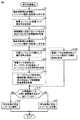
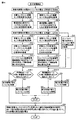
図12は本実施の形態の第3変形例に係る部分放電検出方法の処理手順を示すフローチャートである。図12に示すステップのうち、図6に示すフローチャートに示すステップと実質的に同一の処理を行うものについては、同一のステップ番号を付与している。具体的には、N個(N≧4)の音響センサ30が装着されているとして、例えば、ステップS4_1については、1番目の音響センサ30について、図6のステップS4と実質的に同一の処理が実行されることを示す。
FIG. 12 is a flowchart showing the processing procedure of the partial discharge detection method according to the third modification of the present embodiment. Of the steps shown in FIG. 12, those that perform substantially the same processing as the steps shown in the flowchart of FIG. 6 are given the same step numbers. Specifically, assuming that N (N ≧ 4)
図12を参照して、まず、検査対象物である電力用変圧器1の充電部にインパルス電圧(波高値V2:第2のインパルス電圧)が印加される(ステップS2)。そして、音響センサ30の各々について、ステップS4およびS6が実行されて、ノイズ成分26(ノイズ成分)を決定するための、各音響センサ30固有の時間波形f2(t)(参照信号)が取得される。
Referring to FIG. 12, first, an impulse voltage (crest value V2: second impulse voltage) is applied to the charging portion of
続いて、検査対象物である電力用変圧器1の充電部に、標準規格を満たすインパルス電圧(波高値V1:第1のインパルス電圧)が印加される(ステップS8)。すると、インパルス電圧の印加が開始されたタイミングが取得される(ステップS16)。
Subsequently, an impulse voltage (crest value V1: first impulse voltage) satisfying the standard is applied to the charging part of the
ステップS16と並行して、音響センサ30の各々について、ステップS10〜S14が実行されて、機械振動除去信号(第3の測定信号)がそれぞれ取得される。さらに、音響センサ30の各々について、対応する機械振動除去信号において、高電圧充電部と音響センサ30との位置関係で決まる各音響センサ30に固有の時間範囲t1〜t2の間に音響信号成分が現れているか否かが判断される(ステップS18)。所定の時間範囲t1〜t2の間に音響信号成分が現れていない場合(ステップS18においてNOの場合)には、検査対象物である電力用変圧器1の内部において部分放電が発生していないと判断される(ステップS22)。
In parallel with step S <b> 16, steps S <b> 10 to S <b> 14 are executed for each of the
これに対して、所定の時間範囲t1〜t2の間に音響信号成分が現れている場合(ステップS18においてYESの場合)には、検査対象物である電力用変圧器1の内部において部分放電が発生していると判断される(ステップS20)。すると、ステップS30の部分放電が発生している位置の標定処理が実行される。なお、電力用変圧器1の内部で部分放電が発生している場合には、通常は、すべての音響センサ30について、ステップS18においてYESと判断されることになる。
On the other hand, when an acoustic signal component appears in the predetermined time range t1 to t2 (in the case of YES in step S18), partial discharge occurs in the
このように、検査対象物の外面に複数の音響センサ30を装着し、音響センサ測定信号20(第1の測定信号)を取得するステップS10と、ローパスフィルタ処理信号(第2の測定信号)を取得するステップS12と、機械振動除去信号(第3の測定信号)を取得するステップS14と、検査対象物での部分放電の発生の有無を判断するステップS18とが、複数の音響センサ30の別にそれぞれ実行される。
As described above, the step S10 for obtaining the acoustic sensor measurement signal 20 (first measurement signal) by attaching the plurality of
そして、検査対象物である電力用変圧器1の内部で部分放電が発生していると判断されると(ステップS18においてYESの場合)、複数の音響センサ30からそれぞれ取得された複数の機械振動除去信号において部分放電の発生を示す時間波形が現れるタイミングの差に基づいて、部分放電の発生位置が標定される(ステップS30)。すなわち、各音響センサ30に現れる部分放電に起因する音響信号の時間差をもとに、部分放電の発生位置が標定される。
And if it is judged that the partial discharge has generate | occur | produced inside the
本変形例によれば、電気機器の雷インパルス耐電圧試験時において、複数の音響センサ30を用いて、各音響センサ30によって部分放電に起因する音響信号を検出し、それぞれに現れる部分放電を示す時間波形の時間差に基づいて、電力用変圧器1の内部における部分放電の発生箇所を標定することが可能となる。そのため、電気機器の設計にフィードバックしたり、補修時における有益な情報を取得したりすることができる。
According to this modification, during a lightning impulse withstand voltage test of an electrical device, a plurality of
[H.利点]
本実施の形態に係る部分放電検出方法によれば、電気機器の雷インパルス耐電圧試験時において、インパルス電圧発生装置10から放射される電磁ノイズによる影響、インパルス電圧を印加することで検査対象物に充電電流が流れることで生じる検査対象物自体の機械振動の影響、および、外来ノイズの影響を除去した上で、機器内部で発生する部分放電を判断する。そのため、雷インパルス耐電圧試験時といった外来からのノイズが多い状態であっても、機器内部で発生する部分放電を適切に検出することができる。
[H. advantage]
According to the partial discharge detection method according to the present embodiment, the influence of electromagnetic noise radiated from the
上述の実施の形態として例示した構成は、本発明の実施の形態の一例であり、別の公知の技術と組み合わせることも可能であるし、本発明の要旨を逸脱しない範囲で、一部を省略する等、変更して構成することも可能である。 The configuration illustrated as the above-described embodiment is an example of the embodiment of the present invention, and can be combined with another known technique, and a part thereof is omitted without departing from the gist of the present invention. It is also possible to change and configure it.
今回開示された実施の形態はすべての点で例示であって制限的なものではないと考えられるべきである。本発明の範囲は、上記した説明ではなく、特許請求の範囲によって示され、特許請求の範囲と均等の意味および範囲内でのすべての変更が含まれることが意図される。 The embodiment disclosed this time should be considered as illustrative in all points and not restrictive. The scope of the present invention is defined by the terms of the claims, rather than the description above, and is intended to include any modifications within the scope and meaning equivalent to the terms of the claims.
1 電力用変圧器、2 鉄心、3 コイル、4 タンク、6 印加ケーブル、10 インパルス電圧発生装置、12 コンデンサ、14 球ギャップ、16 入力端子対、17 放電抵抗、18 波頭長調整用コンデンサ、20 音響センサ測定信号、30 音響センサ、100 部分放電検出装置、102 入力回路、104 ローパスフィルタ、106 波形記録部、108 信号処理部。 1 power transformer, 2 iron core, 3 coil, 4 tank, 6 applied cable, 10 impulse voltage generator, 12 capacitor, 14 ball gap, 16 input terminal pair, 17 discharge resistance, 18 wave head length adjusting capacitor, 20 acoustic Sensor measurement signal, 30 acoustic sensor, 100 partial discharge detection device, 102 input circuit, 104 low-pass filter, 106 waveform recording unit, 108 signal processing unit.
Claims (6)
前記第1のインパルス電圧の印加が開始されたタイミングを取得するステップと、
前記検査対象物の外面に装着された音響センサによって第1の測定信号を取得するステップと、
前記第1の測定信号にローパスフィルタを適用することで第2の測定信号を取得するステップと、
前記第2の測定信号から前記検査対象物の機械振動に起因するノイズ成分を除去することで第3の測定信号を取得するステップと、
前記取得されたタイミングを基準として、前記検査対象物における前記充電部と前記音響センサとの位置関係に応じて定まる有効測定期間内に現れる、前記第3の測定信号の時間波形に基づいて、前記検査対象物での部分放電の発生の有無を判断するステップとを備え、
前記ノイズ成分は、前記検査対象物で部分放電を発生させない、前記第1のインパルス電圧より低い第2のインパルス電圧を前記検査対象物の前記充電部に印加したときに、前記音響センサによって取得される第4の測定信号に基づいて決定される、部分放電検出方法。 Applying a first impulse voltage to the charging part of the inspection object;
Obtaining a timing at which application of the first impulse voltage is started;
Obtaining a first measurement signal by an acoustic sensor mounted on the outer surface of the inspection object;
Obtaining a second measurement signal by applying a low pass filter to the first measurement signal;
Obtaining a third measurement signal by removing a noise component caused by mechanical vibration of the inspection object from the second measurement signal;
Based on the time waveform of the third measurement signal, which appears within an effective measurement period determined according to the positional relationship between the charging unit and the acoustic sensor in the inspection object, based on the acquired timing, And determining whether or not partial discharge has occurred in the inspection object,
The noise component is acquired by the acoustic sensor when a second impulse voltage lower than the first impulse voltage that does not cause partial discharge in the inspection object is applied to the charging unit of the inspection object. A partial discharge detection method that is determined based on the fourth measurement signal.
前記音響センサによって前記第4の測定信号を取得するステップと、
前記第4の測定信号に前記ローパスフィルタを適用することで前記ノイズ成分を決定するための参照信号を取得するステップとをさらに備える、請求項1に記載の部分放電検出方法。 Applying the second impulse voltage to the charging unit of the inspection object;
Obtaining the fourth measurement signal by the acoustic sensor;
The partial discharge detection method according to claim 1, further comprising: obtaining a reference signal for determining the noise component by applying the low-pass filter to the fourth measurement signal.
前記検査対象物で部分放電が発生していると判断されると、複数の音響センサからそれぞれ取得された複数の第3の測定信号において部分放電の発生を示す時間波形が現れるタイミングの差に基づいて、部分放電の発生位置を標定するステップとをさらに備える、請求項1または2に記載の部分放電検出方法。 Attaching a plurality of acoustic sensors to the outer surface of the inspection object, obtaining the first measurement signal, obtaining the second measurement signal, and obtaining the third measurement signal; Determining whether or not partial discharge has occurred in the inspection object, and performing each separately for the plurality of acoustic sensors;
When it is determined that a partial discharge has occurred in the inspection object, based on a difference in timing at which time waveforms indicating the occurrence of partial discharge appear in a plurality of third measurement signals respectively acquired from a plurality of acoustic sensors. The partial discharge detection method according to claim 1, further comprising a step of locating a partial discharge occurrence position.
第1のインパルス電圧の前記検査対象物への印加が開始されたタイミングを取得するタイミング取得手段と、
前記検査対象物の外面に装着される音響センサと、
前記音響センサで検出された第1の測定信号にローパスフィルタを適用することで第2の測定信号を出力する第1の信号処理部と、
前記第2の測定信号から前記検査対象物の機械振動に起因するノイズ成分を除去することで第3の測定信号を出力する第2の信号処理部と、
前記取得されたタイミングを基準として、前記検査対象物における前記充電部と前記音響センサとの位置関係に応じて定まる有効測定期間内に現れる、前記第3の測定信号の時間波形に基づいて、前記検査対象物での部分放電の発生の有無を判断する判断手段とを備え、
前記ノイズ成分は、前記検査対象物で部分放電を発生させない、前記第1のインパルス電圧より低い第2のインパルス電圧を前記検査対象物の前記充電部に印加したときに、前記音響センサによって取得される第4の測定信号に基づいて決定される、部分放電検出装置。 A partial discharge detection device for detecting a partial discharge generated by applying an impulse voltage to a charged part of an inspection object,
Timing acquisition means for acquiring timing at which application of the first impulse voltage to the inspection object is started;
An acoustic sensor mounted on the outer surface of the inspection object;
A first signal processing unit that outputs a second measurement signal by applying a low-pass filter to the first measurement signal detected by the acoustic sensor;
A second signal processing unit that outputs a third measurement signal by removing a noise component caused by mechanical vibration of the inspection object from the second measurement signal;
Based on the time waveform of the third measurement signal, which appears within an effective measurement period determined according to the positional relationship between the charging unit and the acoustic sensor in the inspection object, based on the acquired timing, And a judging means for judging whether or not partial discharge occurs in the inspection object,
The noise component is acquired by the acoustic sensor when a second impulse voltage lower than the first impulse voltage that does not cause partial discharge in the inspection object is applied to the charging unit of the inspection object. A partial discharge detection device determined based on the fourth measurement signal.
Priority Applications (1)
| Application Number | Priority Date | Filing Date | Title |
|---|---|---|---|
| JP2013255684A JP6008833B2 (en) | 2013-12-11 | 2013-12-11 | Partial discharge detection method and partial discharge detection apparatus |
Applications Claiming Priority (1)
| Application Number | Priority Date | Filing Date | Title |
|---|---|---|---|
| JP2013255684A JP6008833B2 (en) | 2013-12-11 | 2013-12-11 | Partial discharge detection method and partial discharge detection apparatus |
Publications (2)
| Publication Number | Publication Date |
|---|---|
| JP2015114185A true JP2015114185A (en) | 2015-06-22 |
| JP6008833B2 JP6008833B2 (en) | 2016-10-19 |
Family
ID=53528111
Family Applications (1)
| Application Number | Title | Priority Date | Filing Date |
|---|---|---|---|
| JP2013255684A Active JP6008833B2 (en) | 2013-12-11 | 2013-12-11 | Partial discharge detection method and partial discharge detection apparatus |
Country Status (1)
| Country | Link |
|---|---|
| JP (1) | JP6008833B2 (en) |
Cited By (4)
| Publication number | Priority date | Publication date | Assignee | Title |
|---|---|---|---|---|
| JP2019184246A (en) * | 2018-04-02 | 2019-10-24 | シンフォニアテクノロジー株式会社 | Safety device for electrical device |
| CN112305300A (en) * | 2019-07-31 | 2021-02-02 | 株洲中车时代半导体有限公司 | A voltage detection sensor and system |
| CN116754910A (en) * | 2023-08-14 | 2023-09-15 | 广东电网有限责任公司珠海供电局 | Cable partial discharge monitoring method, system and equipment based on multi-channel optical fiber differential |
| CN120801963A (en) * | 2025-09-12 | 2025-10-17 | 武汉摩恩智能电气有限公司 | Integrated partial discharge-free withstand voltage test device and partial discharge detection method |
Citations (3)
| Publication number | Priority date | Publication date | Assignee | Title |
|---|---|---|---|---|
| JPS6069570A (en) * | 1983-09-26 | 1985-04-20 | Fuji Electric Corp Res & Dev Ltd | Impulse corona detector of stationary electric apparatus |
| JPH0222569A (en) * | 1988-07-12 | 1990-01-25 | Mitsubishi Electric Corp | Partial discharge detecting device |
| JPH04194762A (en) * | 1990-11-28 | 1992-07-14 | Toshiba Corp | Device for monitoring partial discharge of electric apparatus |
-
2013
- 2013-12-11 JP JP2013255684A patent/JP6008833B2/en active Active
Patent Citations (3)
| Publication number | Priority date | Publication date | Assignee | Title |
|---|---|---|---|---|
| JPS6069570A (en) * | 1983-09-26 | 1985-04-20 | Fuji Electric Corp Res & Dev Ltd | Impulse corona detector of stationary electric apparatus |
| JPH0222569A (en) * | 1988-07-12 | 1990-01-25 | Mitsubishi Electric Corp | Partial discharge detecting device |
| JPH04194762A (en) * | 1990-11-28 | 1992-07-14 | Toshiba Corp | Device for monitoring partial discharge of electric apparatus |
Cited By (6)
| Publication number | Priority date | Publication date | Assignee | Title |
|---|---|---|---|---|
| JP2019184246A (en) * | 2018-04-02 | 2019-10-24 | シンフォニアテクノロジー株式会社 | Safety device for electrical device |
| CN112305300A (en) * | 2019-07-31 | 2021-02-02 | 株洲中车时代半导体有限公司 | A voltage detection sensor and system |
| CN112305300B (en) * | 2019-07-31 | 2023-11-03 | 株洲中车时代半导体有限公司 | A voltage detection sensor and system |
| CN116754910A (en) * | 2023-08-14 | 2023-09-15 | 广东电网有限责任公司珠海供电局 | Cable partial discharge monitoring method, system and equipment based on multi-channel optical fiber differential |
| CN116754910B (en) * | 2023-08-14 | 2024-01-09 | 广东电网有限责任公司珠海供电局 | Cable partial discharge monitoring method, system and equipment based on multipath optical fiber difference |
| CN120801963A (en) * | 2025-09-12 | 2025-10-17 | 武汉摩恩智能电气有限公司 | Integrated partial discharge-free withstand voltage test device and partial discharge detection method |
Also Published As
| Publication number | Publication date |
|---|---|
| JP6008833B2 (en) | 2016-10-19 |
Similar Documents
| Publication | Publication Date | Title |
|---|---|---|
| JP6045757B2 (en) | Power device partial discharge determination method, partial discharge determination device, partial discharge determination system, and method of manufacturing power device including partial discharge determination method | |
| EP3182114B1 (en) | Partial discharge monitoring of electrical machines using acoustic emission sensors and electrical sensors | |
| GB2536989B (en) | Condition monitoring method and apparatus for high-voltage AC electrical systems | |
| JP5530966B2 (en) | Method and apparatus for testing insulation performance of gas insulation equipment | |
| JPS62250378A (en) | Method and device for recognizing trouble of electric facility and making sure position thereof | |
| EP2453247A1 (en) | Partial discharge coupler for application on high voltage generator bus works | |
| JP2009115505A (en) | Winding inspection apparatus and inspection method | |
| Zhao et al. | Performance evaluation of online transformer internal fault detection based on transient overvoltage signals | |
| JP6008833B2 (en) | Partial discharge detection method and partial discharge detection apparatus | |
| Abadie et al. | Influence of pressure on partial discharge spectra | |
| CN106526406A (en) | Inter-tern short-circuit detection device, analysis method and device for voltage transformer | |
| EP3754348A1 (en) | Systems and methods for acoustically detecting dielectric breakdown and partial discharge events in electrical devices | |
| Bagheri et al. | Bushing characteristic impacts on on-line frequency response analysis of transformer winding | |
| KR101886192B1 (en) | Apparatus for diagnosing a power transformer | |
| JP2010204067A (en) | Device for measuring partial discharge occurrence frequency | |
| JP5204558B2 (en) | Discharge measuring device for impulse test and discharge discrimination method | |
| US8193818B2 (en) | Partial corona discharge detection | |
| JP2008215864A (en) | Partial discharge detection device and partial discharge detection method for rotating electrical machine | |
| JP7339881B2 (en) | Partial discharge detection device and partial discharge detection method | |
| JP2019117114A (en) | Partial discharge detector and partial discharge detection method | |
| CN115877050B (en) | High-frequency oscillation suppressor and test circuit for neutral point current waveform during lightning impulse | |
| Fornasari et al. | Partial discharge measurements in electrical machines controlled by variable speed drives: From design validation to permanent PD monitoring | |
| Ziomek et al. | Location and recognition of partial discharge sources in a power transformer using advanced acoustic emission method | |
| Lopes et al. | A methodology to predict the lightning insulation strength for distribution transformers by applications of reduced lightning standard impulse voltages | |
| Pfeffer et al. | Onsite experiences with multi-terminal IEC PD measurements and UHF PD measurements |
Legal Events
| Date | Code | Title | Description |
|---|---|---|---|
| A621 | Written request for application examination |
Free format text: JAPANESE INTERMEDIATE CODE: A621 Effective date: 20151021 |
|
| A977 | Report on retrieval |
Free format text: JAPANESE INTERMEDIATE CODE: A971007 Effective date: 20160804 |
|
| TRDD | Decision of grant or rejection written | ||
| A01 | Written decision to grant a patent or to grant a registration (utility model) |
Free format text: JAPANESE INTERMEDIATE CODE: A01 Effective date: 20160816 |
|
| A61 | First payment of annual fees (during grant procedure) |
Free format text: JAPANESE INTERMEDIATE CODE: A61 Effective date: 20160913 |
|
| R150 | Certificate of patent or registration of utility model |
Ref document number: 6008833 Country of ref document: JP Free format text: JAPANESE INTERMEDIATE CODE: R150 |
|
| R250 | Receipt of annual fees |
Free format text: JAPANESE INTERMEDIATE CODE: R250 |
|
| R250 | Receipt of annual fees |
Free format text: JAPANESE INTERMEDIATE CODE: R250 |
|
| R250 | Receipt of annual fees |
Free format text: JAPANESE INTERMEDIATE CODE: R250 |
|
| R250 | Receipt of annual fees |
Free format text: JAPANESE INTERMEDIATE CODE: R250 |
|
| R250 | Receipt of annual fees |
Free format text: JAPANESE INTERMEDIATE CODE: R250 |
|
| R250 | Receipt of annual fees |
Free format text: JAPANESE INTERMEDIATE CODE: R250 |
|
| R250 | Receipt of annual fees |
Free format text: JAPANESE INTERMEDIATE CODE: R250 |