JP2015114172A - Image processing apparatus, microscope system, image processing method, and image processing program - Google Patents
Image processing apparatus, microscope system, image processing method, and image processing program Download PDFInfo
- Publication number
- JP2015114172A JP2015114172A JP2013255413A JP2013255413A JP2015114172A JP 2015114172 A JP2015114172 A JP 2015114172A JP 2013255413 A JP2013255413 A JP 2013255413A JP 2013255413 A JP2013255413 A JP 2013255413A JP 2015114172 A JP2015114172 A JP 2015114172A
- Authority
- JP
- Japan
- Prior art keywords
- shape
- image
- tissue
- organelle
- image processing
- Prior art date
- Legal status (The legal status is an assumption and is not a legal conclusion. Google has not performed a legal analysis and makes no representation as to the accuracy of the status listed.)
- Pending
Links
- 238000012545 processing Methods 0.000 title claims abstract description 80
- 238000003672 processing method Methods 0.000 title claims description 12
- 210000001519 tissue Anatomy 0.000 claims description 158
- 238000000034 method Methods 0.000 claims description 77
- 210000003463 organelle Anatomy 0.000 claims description 61
- 238000004364 calculation method Methods 0.000 claims description 30
- 238000003384 imaging method Methods 0.000 claims description 20
- 230000008569 process Effects 0.000 claims description 10
- 210000003470 mitochondria Anatomy 0.000 claims description 9
- 238000005315 distribution function Methods 0.000 claims description 7
- 210000003205 muscle Anatomy 0.000 claims description 6
- 238000012886 linear function Methods 0.000 claims description 4
- 210000002435 tendon Anatomy 0.000 claims description 4
- 210000004204 blood vessel Anatomy 0.000 claims description 3
- 238000000611 regression analysis Methods 0.000 claims description 3
- 210000005036 nerve Anatomy 0.000 claims description 2
- 238000002360 preparation method Methods 0.000 abstract description 3
- 230000006870 function Effects 0.000 description 74
- 210000004126 nerve fiber Anatomy 0.000 description 31
- 238000005286 illumination Methods 0.000 description 26
- 238000010586 diagram Methods 0.000 description 19
- 230000003287 optical effect Effects 0.000 description 15
- 239000013598 vector Substances 0.000 description 14
- 238000006243 chemical reaction Methods 0.000 description 13
- 238000012986 modification Methods 0.000 description 12
- 230000004048 modification Effects 0.000 description 12
- 238000011156 evaluation Methods 0.000 description 11
- WZUVPPKBWHMQCE-UHFFFAOYSA-N Haematoxylin Chemical compound C12=CC(O)=C(O)C=C2CC2(O)C1C1=CC=C(O)C(O)=C1OC2 WZUVPPKBWHMQCE-UHFFFAOYSA-N 0.000 description 8
- 238000003860 storage Methods 0.000 description 7
- 230000005540 biological transmission Effects 0.000 description 5
- YQGOJNYOYNNSMM-UHFFFAOYSA-N eosin Chemical compound [Na+].OC(=O)C1=CC=CC=C1C1=C2C=C(Br)C(=O)C(Br)=C2OC2=C(Br)C(O)=C(Br)C=C21 YQGOJNYOYNNSMM-UHFFFAOYSA-N 0.000 description 5
- 239000000835 fiber Substances 0.000 description 5
- 238000004458 analytical method Methods 0.000 description 4
- 238000013500 data storage Methods 0.000 description 4
- 210000000981 epithelium Anatomy 0.000 description 4
- 238000009499 grossing Methods 0.000 description 4
- 210000001087 myotubule Anatomy 0.000 description 4
- 238000007781 pre-processing Methods 0.000 description 4
- 238000010186 staining Methods 0.000 description 4
- 241000270295 Serpentes Species 0.000 description 3
- 210000000601 blood cell Anatomy 0.000 description 3
- 230000008602 contraction Effects 0.000 description 3
- 230000005484 gravity Effects 0.000 description 3
- 238000007490 hematoxylin and eosin (H&E) staining Methods 0.000 description 3
- 230000010354 integration Effects 0.000 description 3
- 230000000877 morphologic effect Effects 0.000 description 3
- 235000005811 Viola adunca Nutrition 0.000 description 2
- 240000009038 Viola odorata Species 0.000 description 2
- 235000013487 Viola odorata Nutrition 0.000 description 2
- 235000002254 Viola papilionacea Nutrition 0.000 description 2
- 230000008859 change Effects 0.000 description 2
- 210000000805 cytoplasm Anatomy 0.000 description 2
- 238000013213 extrapolation Methods 0.000 description 2
- 238000003703 image analysis method Methods 0.000 description 2
- 238000003709 image segmentation Methods 0.000 description 2
- 239000011159 matrix material Substances 0.000 description 2
- 230000015654 memory Effects 0.000 description 2
- 210000001700 mitochondrial membrane Anatomy 0.000 description 2
- 210000003101 oviduct Anatomy 0.000 description 2
- 238000010827 pathological analysis Methods 0.000 description 2
- 238000012805 post-processing Methods 0.000 description 2
- 230000009467 reduction Effects 0.000 description 2
- 230000011218 segmentation Effects 0.000 description 2
- 238000007447 staining method Methods 0.000 description 2
- 238000002945 steepest descent method Methods 0.000 description 2
- 102000008186 Collagen Human genes 0.000 description 1
- 108010035532 Collagen Proteins 0.000 description 1
- 241000282342 Martes americana Species 0.000 description 1
- 244000061458 Solanum melongena Species 0.000 description 1
- 235000002597 Solanum melongena Nutrition 0.000 description 1
- 210000001361 achilles tendon Anatomy 0.000 description 1
- 238000013459 approach Methods 0.000 description 1
- 238000013528 artificial neural network Methods 0.000 description 1
- 210000003050 axon Anatomy 0.000 description 1
- 210000000013 bile duct Anatomy 0.000 description 1
- 238000004422 calculation algorithm Methods 0.000 description 1
- 229920001436 collagen Polymers 0.000 description 1
- 238000004891 communication Methods 0.000 description 1
- 238000012790 confirmation Methods 0.000 description 1
- 210000002808 connective tissue Anatomy 0.000 description 1
- 239000000470 constituent Substances 0.000 description 1
- 238000012937 correction Methods 0.000 description 1
- 238000005520 cutting process Methods 0.000 description 1
- 238000003066 decision tree Methods 0.000 description 1
- 230000001419 dependent effect Effects 0.000 description 1
- 238000001514 detection method Methods 0.000 description 1
- 201000010099 disease Diseases 0.000 description 1
- 208000037265 diseases, disorders, signs and symptoms Diseases 0.000 description 1
- 210000004177 elastic tissue Anatomy 0.000 description 1
- 238000005516 engineering process Methods 0.000 description 1
- 238000000556 factor analysis Methods 0.000 description 1
- 238000001914 filtration Methods 0.000 description 1
- 210000001035 gastrointestinal tract Anatomy 0.000 description 1
- 230000002068 genetic effect Effects 0.000 description 1
- 230000000762 glandular Effects 0.000 description 1
- 210000003734 kidney Anatomy 0.000 description 1
- 210000003041 ligament Anatomy 0.000 description 1
- 230000001926 lymphatic effect Effects 0.000 description 1
- 238000010801 machine learning Methods 0.000 description 1
- 238000000386 microscopy Methods 0.000 description 1
- 239000000203 mixture Substances 0.000 description 1
- 210000004165 myocardium Anatomy 0.000 description 1
- 210000003365 myofibril Anatomy 0.000 description 1
- 210000000944 nerve tissue Anatomy 0.000 description 1
- 210000002241 neurite Anatomy 0.000 description 1
- 230000006911 nucleation Effects 0.000 description 1
- 238000010899 nucleation Methods 0.000 description 1
- 238000003909 pattern recognition Methods 0.000 description 1
- 238000012567 pattern recognition method Methods 0.000 description 1
- 238000000513 principal component analysis Methods 0.000 description 1
- 102000004169 proteins and genes Human genes 0.000 description 1
- 108090000623 proteins and genes Proteins 0.000 description 1
- 239000004065 semiconductor Substances 0.000 description 1
- 210000002027 skeletal muscle Anatomy 0.000 description 1
- 210000002460 smooth muscle Anatomy 0.000 description 1
- 238000004611 spectroscopical analysis Methods 0.000 description 1
- 238000007619 statistical method Methods 0.000 description 1
- 210000003699 striated muscle Anatomy 0.000 description 1
- 238000012706 support-vector machine Methods 0.000 description 1
- 210000003437 trachea Anatomy 0.000 description 1
- 210000001170 unmyelinated nerve fiber Anatomy 0.000 description 1
- 210000000626 ureter Anatomy 0.000 description 1
- 210000001635 urinary tract Anatomy 0.000 description 1
- 210000001177 vas deferen Anatomy 0.000 description 1
- 230000009278 visceral effect Effects 0.000 description 1
- XLYOFNOQVPJJNP-UHFFFAOYSA-N water Substances O XLYOFNOQVPJJNP-UHFFFAOYSA-N 0.000 description 1
Images
Landscapes
- Investigating Or Analysing Biological Materials (AREA)
- Investigating Or Analysing Materials By Optical Means (AREA)
- Image Processing (AREA)
- Image Analysis (AREA)
Abstract
Description
本発明は、生体標本の顕微鏡観察画像に写った繊維状組織又は管状組織の形状を認識する画像処理装置、顕微鏡システム、画像処理方法、及び画像処理プログラムに関する。 The present invention relates to an image processing apparatus, a microscope system, an image processing method, and an image processing program for recognizing the shape of a fibrous tissue or tubular tissue reflected in a microscope observation image of a biological specimen.
従来、生体観察や病理診断においては、生体から採取した組織標本の顕微鏡観察画像に写った組織が有する特徴に基づいて、生体の状態や病状を判断することが行われている。例えば、特許文献1には、染色された組織標本の画像から、画素の輝度値に基づいて細胞核領域、細胞質領域、腺腔領域をそれぞれ抽出し、これらの各領域の形状の特徴を示す基本特徴量を計測し、輝度値及び基本特徴量に基づき、組織標本の病状に応じて限定的に出現する特殊領域がこれらの各領域に存在するか否かを確認する技術が開示されている。
Conventionally, in living body observation and pathological diagnosis, the state of a living body and a medical condition are determined based on the characteristics of a tissue shown in a microscopic observation image of a tissue specimen collected from the living body. For example,
上記特許文献1においては、生体の状態や病状の判断にあたって、病状の確認に利用される特殊領域以外の領域の特徴、例えば、組織の境界や該境界内部の領域の特徴は考慮されておらず、精度の良い境界認識も行われていない。しかしながら、組織の境界によって特定される該組織の形状や、境界によって区切られる領域ごと(内部領域及び外部領域)の特徴も、病理診断等においては重要な判断要素となることがある。例えば、繊維状組織や管状組織の境界を精度良く認識することができれば、それらの境界情報を種々の診断に利用できる、或いは新しい解剖学的知見が得られる可能性がある。
In the above-mentioned
本発明は上記に鑑みてなされたものであり、生体から採取した組織標本の画像に写った繊維状組織又は管状組織の境界の認識精度を向上させる画像処理装置、顕微鏡システム、画像処理方法、及び画像処理プログラムを提供することを目的とする。 The present invention has been made in view of the above, and an image processing apparatus, a microscope system, an image processing method, and an image processing apparatus that improve the recognition accuracy of the boundary of a fibrous tissue or tubular tissue reflected in an image of a tissue specimen collected from a living body, and An object is to provide an image processing program.
上述した課題を解決し、目的を達成するために、本発明に係る画像処理装置は、生体から採取した組織標本の画像を取得する画像取得部と、前記画像に写った所定の細胞小器官の形状を個別に認識する細胞小器官認識部と、前記所定の細胞小器官の形状に基づいて、前記画像に写った繊維状組織又は管状組織の形状を認識する組織認識部と、を備えることを特徴とする。 In order to solve the above-described problems and achieve the object, an image processing apparatus according to the present invention includes an image acquisition unit that acquires an image of a tissue specimen collected from a living body, and a predetermined organelle captured in the image. An organelle recognizing unit that individually recognizes the shape, and a tissue recognizing unit that recognizes the shape of the fibrous tissue or the tubular tissue reflected in the image based on the shape of the predetermined organelle. Features.
上記画像処理装置において、前記細胞小器官認識部は、前記画像を構成する各画素が前記所定の細胞小器官を表す画素であるか否かを判定し、前記所定の細胞小器官を表すと判定された画素の領域である細胞小器官領域の形状を認識する細胞小器官形状認識部と、前記細胞小器官領域の形状を定量化した情報である細胞小器官情報を生成する細胞小器官情報生成部と、を備えることを特徴とする。 In the image processing apparatus, the organelle recognition unit determines whether each pixel constituting the image is a pixel representing the predetermined organelle, and determines that the pixel represents the predetermined organelle. An organelle shape recognition unit for recognizing the shape of an organelle region that is a region of a pixel, and organelle information generation that generates organelle information that is information obtained by quantifying the shape of the organelle region And a section.
上記画像処理装置において、前記細胞小器官情報は、前記細胞小器官領域の形状を直線に近似したときの該直線の傾き又は該直線と所定の角度をなす直線の傾きであることを特徴とする。 In the image processing apparatus, the organelle information is a slope of the straight line when the shape of the organelle region is approximated to a straight line or a slope of a straight line that forms a predetermined angle with the straight line. .
上記画像処理装置において、前記直線は、前記細胞小器官領域の形状を回帰分析により近似した一次関数によって表される直線、又は前記細胞小器官領域の形状の慣性主軸であることを特徴とする。 In the image processing apparatus, the straight line is a straight line represented by a linear function obtained by approximating the shape of the organelle region by regression analysis, or an inertia main axis of the shape of the organelle region.
上記画像処理装置において、前記組織認識部は、前記画像から抽出された複数の前記細胞小器官領域についてそれぞれ生成された前記細胞小器官情報の統計情報を算出する統計情報算出部と、前記統計情報算出部により算出された前記統計情報に基づいて、前記繊維状組織又は前記管状組織の形状を認識する組織形状認識部と、を備えることを特徴とする。 In the image processing apparatus, the tissue recognition unit calculates statistical information of the organelle information generated for each of the plurality of organelle regions extracted from the image, and the statistical information A tissue shape recognition unit for recognizing the shape of the fibrous tissue or the tubular tissue based on the statistical information calculated by the calculation unit.
上記画像処理装置において、前記統計情報は、平均値、中央値、最頻値、分散、標準偏差、尖度、歪度、エントロピー及び分布関数のうちの少なくとも1つであることを特徴とする。 In the image processing apparatus, the statistical information is at least one of an average value, median value, mode value, variance, standard deviation, kurtosis, skewness, entropy, and distribution function.
上記画像処理装置において、前記組織形状認識部は、前記画像内における前記繊維状組織又は前記管状組織の形状を推定し、該推定した前記繊維状組織又は前記管状組織の形状を定量化した形状情報と、前記統計情報算出部によって算出された前記統計情報の算出結果とを比較することにより、前記繊維状組織又は前記管状組織の形状を認識する、ことを特徴とする。 In the image processing apparatus, the tissue shape recognition unit estimates the shape of the fibrous tissue or the tubular tissue in the image, and shape information obtained by quantifying the estimated shape of the fibrous tissue or the tubular tissue. And the calculation result of the statistical information calculated by the statistical information calculation unit to recognize the shape of the fibrous tissue or the tubular tissue.
上記画像処理装置において、前記組織形状認識部は、前記細胞小器官領域の形状を事前知識として用いて前記繊維状組織又は前記管状組織の形状を認識することを特徴とする。 In the image processing apparatus, the tissue shape recognition unit recognizes the shape of the fibrous tissue or the tubular tissue using the shape of the organelle region as prior knowledge.
上記画像処理装置において、前記所定の細胞小器官は、核又はミトコンドリアであることを特徴とする。 In the image processing apparatus, the predetermined organelle is a nucleus or a mitochondria.
上記画像処理装置において、前記繊維状組織又は前記管状組織は、神経、筋、腱、及び血管のうちの少なくとも1つであることを特徴とする。 In the image processing apparatus, the fibrous tissue or the tubular tissue is at least one of a nerve, a muscle, a tendon, and a blood vessel.
本発明に係る顕微鏡システムは、前記画像処理装置と、生体から採取した組織標本の拡大像を生成する顕微鏡装置と、前記拡大像を撮像することにより画像を生成して前記画像取得部に入力する撮像部と、を備えることを特徴とする。 The microscope system according to the present invention generates the image by capturing the magnified image by inputting the image processing device, the microscope device that generates the magnified image of the tissue specimen collected from the living body, and inputs the image to the image acquisition unit. And an imaging unit.
本発明に係る画像処理方法は、生体から採取した組織標本の画像を処理する画像処理装置が実行する画像処理方法において、演算部が、画像データを読み込むことにより前記画像を取得する画像取得ステップと、前記演算部が、前記画像に写った所定の細胞小器官の形状を個別に認識する細胞小器官認識ステップと、前記演算部が、前記所定の細胞小器官の形状に基づいて、前記画像に写った繊維状組織又は管状組織の形状を認識する組織認識ステップと、を含むことを特徴とする。 An image processing method according to the present invention is an image processing method executed by an image processing apparatus that processes an image of a tissue specimen collected from a living body, and an image acquisition step in which a calculation unit acquires the image by reading image data; The organelle recognition step for individually recognizing the shape of the predetermined organelle captured in the image, and the computing portion adds the image to the image based on the shape of the organelle. A tissue recognition step of recognizing the shape of the captured fibrous tissue or tubular tissue.
本発明に係る画像処理プログラムは、体から採取した組織標本の画像を取得する画像取得ステップと、前記画像に写った所定の細胞小器官の形状を個別に認識する細胞小器官認識ステップと、前記所定の細胞小器官の形状に基づいて、前記画像に写った繊維状組織又は管状組織の形状を認識する組織認識ステップと、をコンピュータに実行させることを特徴とする。 An image processing program according to the present invention includes an image acquisition step of acquiring an image of a tissue specimen collected from a body, an organelle recognition step of individually recognizing a shape of a predetermined organelle reflected in the image, And a tissue recognition step of recognizing the shape of the fibrous tissue or tubular tissue shown in the image based on the shape of a predetermined organelle.
本発明によれば、画像内で認識された細胞小器官の形状をもとに繊維状組織又は管状組織の形状を認識するので、繊維状組織又は管状組織の形状の認識精度を向上させることが可能となる。 According to the present invention, since the shape of the fibrous tissue or tubular tissue is recognized based on the shape of the organelle recognized in the image, the recognition accuracy of the shape of the fibrous tissue or tubular tissue can be improved. It becomes possible.
以下、本発明に係る画像処理装置、顕微鏡システム、画像処理方法、及び画像処理プログラムの実施の形態について、図面を参照しながら詳細に説明する。なお、これらの実施の形態により本発明が限定されるものではない。また、各図面の記載において、同一部分には同一の符号を付して示している。 Hereinafter, embodiments of an image processing apparatus, a microscope system, an image processing method, and an image processing program according to the present invention will be described in detail with reference to the drawings. Note that the present invention is not limited to these embodiments. Moreover, in description of each drawing, the same code | symbol is attached | subjected and shown to the same part.
(実施の形態1)
図1は、本発明の実施の形態1に係る画像処理装置の構成を示すブロック図である。図1に示すように、実施の形態1に係る画像処理装置10は、当該画像処理装置10に対する指示や情報の入力する際に用いられる入力部11と、処理対象の画像に対応する画像情報(画像データ)を取得する画像取得部12と、処理対象の画像や種々の演算結果を出力する出力部13と、記憶部14と、入力された画像に所定の演算処理を施す演算部15と、これらの各部の動作を制御する制御部16とを備える。また、画像処理装置10に、出力部13から出力された画像や演算結果、その他各種情報を画面に表示する表示装置17を接続しても良い。
(Embodiment 1)
FIG. 1 is a block diagram showing a configuration of an image processing apparatus according to
入力部11は、キーボード、各種ボタン、各種スイッチ等の入力デバイスや、マウスやタッチパネル等のポインティングデバイスを含み、これらのデバイスに対する操作に応じた信号を制御部16に入力する。
The
画像取得部12は、例えば顕微鏡装置に取り付けられた撮像装置(カメラ)やサーバ等(いずれも図示せず)から出力された画像データを当該画像処理装置10に取り込むインタフェースである。画像取得部12は、撮像装置から画像データを直接、リアルタイムに取り込んでも良いし、サーバに一旦保存された画像データを随時取り込んでも良い。
The
ここで、撮像装置は、撮像素子が有する各画素においてR(赤)、G(緑)、B(青)の各バンドにおける画素レベル(画素値)を持つカラー画像を生成可能なカメラを用いて構成される。また、撮像装置は、RGB色空間で表された画素値を、YCbCr色空間で表された画素値に変換した画像データを生成しても良い。画像取得部12は、このような画像データを撮像装置等から取得して記憶部14に記憶させる。
Here, the imaging apparatus uses a camera capable of generating a color image having pixel levels (pixel values) in each band of R (red), G (green), and B (blue) in each pixel included in the imaging element. Composed. The imaging apparatus may generate image data obtained by converting pixel values represented in the RGB color space into pixel values represented in the YCbCr color space. The
記憶部14は、更新記録可能なフラッシュメモリ、RAM、ROM等の半導体メモリや、内蔵若しくはデータ通信端子で接続されたハードディスク、MO、CD−R、DVD−R等の記録媒体及び該記録媒体に記録された情報を読み取る読取装置等によって構成される。記憶部14は、画像取得部12が取り込んだ画像データや、演算部15及び制御部16がそれぞれ実行する各種プログラム及び各種設定情報を記憶する。具体的には、記憶部14は、生体から採取した組織標本の顕微鏡観察画像から繊維状組織又は管状組織の輪郭を認識する画像処理プログラムを記憶するプログラム記憶部141と、画像取得部12が取得した画像データを記憶する画像データ記憶部142とを備える。
The
演算部15は、例えばCPU等のハードウェアによって構成され、プログラム記憶部141に記憶された画像処理プログラムを読み込むことにより、所定の画像処理を実行する。具体的には、演算部15は、画像データ記憶部142に記憶された画像データに対し、必要に応じ、前処理としてホワイトバランス処理、デモザイキング、色変換、濃度変換(ガンマ変換等)、平滑化(ノイズ除去等)、鮮鋭化(エッジ強調等)等の画像処理を施すことにより画像を生成し、生成した画像から繊維状組織又は管状組織の輪郭を認識する画像処理を実行する。演算部15の詳細な構成については、後述する。
The
制御部16は、例えばCPU等のハードウェアによって構成され、プログラム記憶部141に記憶された各種制御プログラムを読み込むことにより、該プログラム記憶部141に記憶された各種設定情報や入力部11から入力された情報に基づいて、当該画像処理装置10を統括的に制御する。
The
表示装置17は、例えば、LCD、ELディスプレイ、CRTディスプレイ等の表示装置によって構成され、画像処理装置10の出力部13から出力された画像や、該画像から抽出された繊維状組織又は管状組織に関する情報等を画面に表示する。
なお、実施の形態1においては、表示装置17を画像処理装置10の外部に設けているが、表示装置17を画像処理装置10の内部に設けても良い。
The
In the first embodiment, the
次に、演算部15の詳細な構成について説明する。
図1に示すように、演算部15は、画像データ記憶部142に記憶された画像データを読み出し、該画像データに対応する画像から、標本内に存在する所定の細胞小器官、具体的には核の形状を個別に認識する細胞小器官認識部の一例としての単一核認識部151と、該単一核認識部151により認識された核の形状に基づいて、当該標本内に存在する繊維状組織又は管状組織の形状を認識する組織認識部152とを備える。
Next, the detailed structure of the calculating
As shown in FIG. 1, the
ここで、繊維状組織とは、上皮組織、結合組織、筋組織、神経組織のことである。具体例としては、筋繊維、筋肉繊維、筋原繊維、筋束、腱、神経繊維、神経繊維束等が挙げられる。より詳細には、弾性繊維、膠原繊維、平滑筋、横紋筋、内臓筋、心筋、骨格筋、靭帯、アキレス腱、無髄無鞘神経繊維、無髄有鞘神経繊維、有髄無鞘神経繊維、有髄有鞘神経繊維等の細長い形状をなす組織のことである。一般に、筋や腱のように、一定の方向に絶えず引っ張る力がかかるような部位においては、力のかかる方向と平行に繊維が緻密に配列される。また、管状組織には、血管、リンパ管、水管、消化管、胆管、気管、輸尿管、細尿管、尿管、マルピーギ管、腎管、原腎管、輸卵管、輸精管、産卵管等が含まれる。 Here, the fibrous tissue refers to epithelial tissue, connective tissue, muscle tissue, and nerve tissue. Specific examples include muscle fibers, muscle fibers, myofibrils, muscle bundles, tendons, nerve fibers, nerve fiber bundles, and the like. More specifically, elastic fiber, collagen fiber, smooth muscle, striated muscle, visceral muscle, myocardium, skeletal muscle, ligament, Achilles tendon, unmyelinated and unsheathed nerve fiber, unmyelinated and sheath-free nerve fiber A tissue having an elongated shape such as a myelinated sheathed nerve fiber. In general, in a portion such as a muscle or a tendon that is constantly pulled in a certain direction, fibers are densely arranged parallel to the direction in which the force is applied. Tubular tissues include blood vessels, lymphatic tubes, water tubes, digestive tracts, bile ducts, trachea, ureteral tubes, urinary tracts, ureters, malpighian tubes, renal tubes, primary kidney tubes, oviduct tubes, vas deferens tubes, oviduct tubes, etc. .
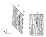
図2は、繊維状組織の一例としての複数の神経繊維を拡大して示す模式図である。図2に示す1本の神経繊維(輪郭BFによって画定される領域)は、軸索や神経突起の単体又は集合体からなり、神経繊維の束又は神経繊維束と表現する場合もある。本出願において神経繊維という場合、神経繊維の束(神経繊維束)を含むものとする。図2においては、神経繊維が伸びる方向(長手方向)をZ方向としている。ここで、生体組織の形態観察において一般的に用いられる染色方法として、ヘマトキシリン・エオジン染色(以下、HE染色という)が知られている。HE染色においては、細胞小器官の1つである核がヘマトキシリンにおいて青紫色に染色され、細胞質がエオジンによって赤色に染色される。それに加えて、ミトコンドリアもエオジンに好適に染色される。これは、ミトコンドリアの外膜や内膜に含まれる様々なたんぱく質の量が他の細胞小器官と比べて多いためと考えられる。 FIG. 2 is an enlarged schematic view showing a plurality of nerve fibers as an example of a fibrous tissue. One nerve fiber (region defined by the contour BF ) shown in FIG. 2 is composed of a single unit or aggregate of axons and neurites, and may be expressed as a nerve fiber bundle or nerve fiber bundle. In the present application, the term “nerve fiber” includes a bundle of nerve fibers (nerve fiber bundle). In FIG. 2, the direction (longitudinal direction) in which the nerve fibers extend is the Z direction. Here, hematoxylin / eosin staining (hereinafter referred to as HE staining) is known as a staining method generally used in morphological observation of living tissue. In HE staining, the nucleus, which is one of organelles, is stained blue-purple in hematoxylin, and the cytoplasm is stained red by eosin. In addition, mitochondria are also favorably stained with eosin. This is probably because the amount of various proteins contained in the outer and inner mitochondrial membranes is higher than in other organelles.
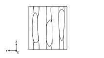
図3は、図2に示す神経繊維のうち、1本の神経繊維(神経繊維束)の一部(例えば領域R1)を拡大して示す模式図である。図3(a)は該標本のYZ平面における断面を示し、図3(b)は該標本のXZ平面における断面を示す。 FIG. 3 is an enlarged schematic diagram showing a part (for example, region R1) of one nerve fiber (nerve fiber bundle) among the nerve fibers shown in FIG. FIG. 3A shows a cross section of the specimen in the YZ plane, and FIG. 3B shows a cross section of the specimen in the XZ plane.
図4は、図3に示す神経繊維の一部(例えば領域R2)を拡大して示す模式図である。図3及び図4に示すように、神経繊維においては、染色されたミトコンドリアが、繊維が伸びる方向に沿って存在していることが観察される。 FIG. 4 is an enlarged schematic view showing a part of the nerve fiber (for example, the region R2) shown in FIG. As shown in FIGS. 3 and 4, in nerve fibers, it is observed that stained mitochondria are present along the direction in which the fibers extend.
また、図示はしないが、筋繊維を同様に染色して観察した場合には、染色された核が、筋繊維が伸びる方向に沿って存在していることが観察される。 Although not shown, when the muscle fibers are similarly stained and observed, it is observed that the dyed nuclei exist along the direction in which the muscle fibers extend.
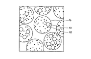
図5は、複数の神経繊維を、該神経繊維が伸びる方向とほぼ直交する面(例えば図2においては、L1−L1線を通る面)で切断した場合の断面を示す模式図である。この場合、図5に示すように、切断面における神経繊維の輪郭BFの形状は、概ね円に近い形状となる。 FIG. 5 is a schematic diagram showing a cross section when a plurality of nerve fibers are cut along a plane that is substantially orthogonal to the direction in which the nerve fibers extend (for example, in FIG. 2, a plane that passes through the line L1-L1). In this case, as shown in FIG. 5, the shape of the nerve fiber outline BF on the cut surface is substantially a circle.
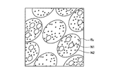
図6は、複数の神経繊維を、該神経繊維が伸びる方向とほぼ直交する面に対して傾斜した面(例えば図2においては、L2−L2線を通る面)で切断した場合の断面を示す模式図である。この場合、切断面における神経繊維の輪郭BFの形状は、切断面の傾斜に応じて扁平な形状となる。 FIG. 6 shows a cross section when a plurality of nerve fibers are cut along a plane inclined with respect to a plane substantially orthogonal to the direction in which the nerve fibers extend (for example, a plane passing through the line L2-L2 in FIG. 2). It is a schematic diagram. In this case, the shape of the outline BF of the nerve fiber on the cut surface is a flat shape according to the inclination of the cut surface.
本願発明者は、このように、種々の繊維状組織や管状組織の標本を様々な面で切断し、各切断面における顕微鏡観察像を鋭意観察した結果、切断面における繊維状組織や管状組織の輪郭形状と、同じ切断面において観察される細胞小器官、具体的には、核やミトコンドリアの形状とに相関があることを見出した。例えば、図5において、核N1やミトコンドリアN2の形状は、その周囲に示す神経繊維の輪郭BFの形状と同様に、概ね円形状をなしている。それに対し、図6において、核N1やミトコンドリアN2の形状は、その周囲に示す神経繊維の輪郭BFの形状と同様に、扁平な形状をなしている。 As described above, the inventors of the present invention cut specimens of various fibrous tissues and tubular tissues on various surfaces, and as a result of intensively observing microscopic observation images on the respective cut surfaces, the results of the fibrous tissues and tubular tissues on the cut surfaces were obtained. It was found that there is a correlation between the contour shape and the organelles observed on the same cut plane, specifically, the shape of the nucleus and mitochondria. For example, in FIG. 5, the shape of the nucleus N1 and the mitochondria N2 is substantially circular, similar to the shape of the nerve fiber outline B F shown in the periphery thereof. On the other hand, in FIG. 6, the shapes of the nucleus N1 and the mitochondria N2 are flat, similar to the shape of the outline BF of the nerve fiber shown around them.
このような観察結果から、本願発明者は、繊維状組織や管状組織の輪郭を認識する際に、核やミトコンドリアといった細胞小器官の形状に関する情報を利用することで、認識精度を向上させることができる本願発明に想到した。 From such observation results, the present inventor can improve recognition accuracy by using information on the shape of organelles such as nuclei and mitochondria when recognizing the outline of fibrous tissue or tubular tissue. The present invention has been conceived.
再び図1を参照すると、単一核認識部151は、処理対象である画像を構成する各画素が核を表す画素であるか否かを判定し、核を表すと判定された画素の領域である核領域の形状を認識する細胞小器官形状認識部の一例としての核形状認識部151aと、認識された核領域の形状を定量化した情報である核情報を生成する細胞小器官情報生成部の一例としての核情報生成部151bとを備える。
Referring to FIG. 1 again, the single
また、組織認識部152は、単一核認識部151によって算出された核領域の核情報の統計情報を算出する統計情報算出部としての統計値算出部152aと、核情報の統計情報の算出結果に基づいて、画像内の繊維状組織又は管状組織の形状を認識する組織形状認識部152bとを備える。
In addition, the
次に、画像処理装置10の動作について説明する。図7は、画像処理装置10の動作を示すフローチャートである。なお、以下においては、標本の観察画像内に存在する繊維状組織の形状を認識する場合を説明するが、管状組織についても同様の手法により形状を認識することができる。また、以下においては、細胞小器官の一例として核の形状に基づいて繊維状組織の形状を認識する場合を説明するが、核の形状の代わりに、ミトコンドリア等、繊維状組織や管状組織が伸びる方向に沿って存在する他の細胞小器官の形状に基づいて、同様に繊維状組織や管状組織の形状を認識することも可能である。
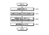
Next, the operation of the
まず、ステップS10において、演算部15は、画像データ記憶部142から画像データを読み込むことにより、処理対象の画像(生体の組織標本の観察画像)を取得する。処理対象の画像は、生体から採取された検体に、少なくとも核及び繊維状組織を染色可能な染色処理(例えば、ヘマトキリシン・エオジン(HE)染色)が施された標本を、顕微鏡装置に設けられた撮像装置で撮像することによって取得されたものである。
First, in step S <b> 10, the
続くステップS11において、単一核認識部151は、ステップS10において取得された画像に対し、必要に応じて、ホワイトバランス処理、デモザイキング、色変換、濃度変換(ガンマ変換等)、平滑化(ノイズ除去等)、鮮鋭化(エッジ強調等)等の前処理(画像処理)を施した上で、画像内に存在する核の領域を個別に認識する処理を行う。図8は、単一核認識部151が実行する核認識処理を示すフローチャートである。
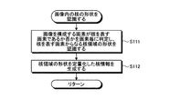
In subsequent step S11, the single
ステップS111において、核形状認識部151aは、画像を構成する画素が核を表す画素であるか否かを画素毎に判定し、核を表す画素からなる核領域の形状を認識する。核を表す画素であるか否かの判定は、例えば、各画素の画素値、又は該画素値から算出される色情報(色差、色比、色相等)に基づいて行われる。具体的には、HE染色が施された標本においては、核が青紫色に染色されるので、画素値から算出される色特徴量が青紫色の色特徴量の範囲に含まれる画素が、核を表す画素であると判定される。 In step S111, the nucleus shape recognition unit 151a determines, for each pixel, whether or not a pixel constituting the image is a pixel representing a nucleus, and recognizes a shape of a nucleus region including pixels representing the nucleus. The determination of whether or not the pixel represents a nucleus is made based on, for example, the pixel value of each pixel or color information (color difference, color ratio, hue, etc.) calculated from the pixel value. Specifically, in the HE-stained specimen, since the nucleus is stained blue-violet, the pixel whose color feature amount calculated from the pixel value is included in the range of the blue-violet color feature amount is the nucleus. It is determined that the pixel represents.
続いて、核形状認識部151aは、核を表す画素と判定した画素群からなる領域、即ち核領域の形状を認識する。核領域の形状の認識方法としては、公知の種々の方法が挙げられる。具体的には、二値化法、p−タイル法、微分ヒストグラム法、モード法、可変閾値法、対応領域探索法、テンプレートマッチング法等の一般的画像解析方法や、動的輪郭法(スネーク法)、領域成長法(極値収束法、分水嶺法)、領域競合法、領域拡張法、分割・統合法、グラフカット法等の輪郭検出方法や、判別分析、因子分析、主成分分析、独立成分分析、決定木、ニューラルネットワーク、自己組織化マップ、ノンパラメトリック手法、遺伝的アルゴリズム、サポートベクターマシーン、ブースティング、ベイズ判別、機械学習、クラスタリング、クラシフィケーション等のパターン認識(識別)方法を用いることができる。 Subsequently, the nucleus shape recognizing unit 151a recognizes a region composed of a pixel group determined as a pixel representing a nucleus, that is, a shape of the nucleus region. As a method for recognizing the shape of the nucleus region, various known methods can be cited. Specifically, a general image analysis method such as a binarization method, a p-tile method, a differential histogram method, a mode method, a variable threshold method, a corresponding region search method, a template matching method, a dynamic contour method (the snake method) ), Contour growth methods (extreme convergence method, diversion method), region competition method, region expansion method, segmentation / integration method, graph cut method, discriminant analysis, factor analysis, principal component analysis, independent component Use pattern recognition (discrimination) methods such as analysis, decision trees, neural networks, self-organizing maps, nonparametric methods, genetic algorithms, support vector machines, boosting, Bayesian discrimination, machine learning, clustering, classification, etc. Can do.
実施の形態1においては、一例として、レベルセット(Level Set Method:LSM)法を用いて核領域の形状を認識する。LSM法とは、画像内において認識対象(例えば、核や繊維)と背景(認識対象外である血球、間質、上皮等)が明確に分離されていない状況であっても、認識対象と背景との境界を認識することができる技術である。LSM法においては、認識対象の輪郭(例えば、核領域の輪郭)の初期値を設定すると共に、エネルギー関数(又は評価関数)を設定し、該エネルギー関数が最小化されるように輪郭を更新することで、輪郭を初期値から認識対象の境界に近づける手法である。 In the first embodiment, as an example, the shape of the nucleus region is recognized using a level set method (LSM) method. The LSM method refers to a recognition target and a background even if the recognition target (eg, nucleus or fiber) and the background (blood cells, stroma, epithelium, etc., which are not the recognition target) are not clearly separated in the image. It is a technology that can recognize the boundary. In the LSM method, an initial value of a contour to be recognized (for example, a contour of a nucleus region) is set, an energy function (or evaluation function) is set, and the contour is updated so that the energy function is minimized. In this way, the contour approaches the boundary of the recognition target from the initial value.
以下においては、図9〜図12を参照しながら、チャン(Chan)らが提案した領域依存のエネルギー関数で定義されるLSM法を核領域の形状認識に適用した例を説明する。なお、エネルギー関数で定義されるLSM法については、特許第4614149号公報、及び、チャン(Chan)等による「Active Contours Without Edges」(IEEE TRANSACTIONS ON IMAGE PROCESSING, Vol. 10, No. 2(2001年2月)、第266〜277頁)も参照されたい。 Hereinafter, an example in which the LSM method defined by the region-dependent energy function proposed by Chan et al. Is applied to the shape recognition of the nuclear region will be described with reference to FIGS. The LSM method defined by the energy function is disclosed in Japanese Patent No. 46614149 and “Active Contours Without Edges” (IEEE TRANSACTIONS ON IMAGE PROCESSING, Vol. 10, No. 2 (2001). (February), pp. 266-277).
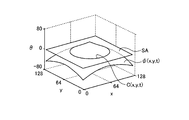
LSM法においては、図9に示すように、3次元のレベルセット関数φ(x,y,t)のゼロ等位面SA、即ち、φ=0となる面において、次式(1)によって与えられる2次元の輪郭C(x,y,t)を表現する。
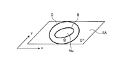
図10は、レベルセット関数φ(x,y,t)をゼロ等位面SAで切った切り口、即ち輪郭Cを概略的に示す図である。次式(2−1)〜(2−3)に示すように、図10に示す領域Ωは輪郭Cの内側の領域を示し、領域Ω*は輪郭Cの外側の領域を示す。
ここでは、説明を簡単にするために、図10に示すように、処理対象の画像内に形状認識の対象である1つの核領域Nuが存在し、輪郭Cが核領域Nuの外側に初期設定されたものとする。また、核領域Nuと背景との境界を符号Bで示す。なお、以下の説明は、核領域Nuが複数個存在する場合であっても、同様に成立する。 Here, in order to simplify the explanation, as shown in FIG. 10, there is one nucleus region Nu as a shape recognition target in the image to be processed, and the contour C is initially set outside the nucleus region Nu. It shall be assumed. Further, a boundary between the nucleus region Nu and the background is indicated by a symbol B. The following description holds true even when there are a plurality of nucleus regions Nu.
核形状認識部151aは、関数φによって与えられる輪郭Cを境界Bと一致させることで、核領域Nuの境界Bを認識することができる。具体的には、核形状認識部151aは、レベルセット関数φに適当な初期値を与え、次式(3)に示すようにエネルギー関数Eが最小となるようにレベルセット関数φを更新することにより、核領域Nuの境界Bを認識する。
図11は、エネルギー関数Eを示すグラフである。図11に示す横軸は、輪郭Cが取り得る形状を定量化した値を示す。このエネルギー関数Eは、輪郭Cが核領域Nuの境界に沿っている程度指標であり、輪郭Cが核領域Nuの境界に完全に沿っているときに極小(C=C(Nu))となる。 FIG. 11 is a graph showing the energy function E. The horizontal axis shown in FIG. 11 indicates a value obtained by quantifying the shape that the contour C can take. This energy function E is a measure of the degree to which the contour C is along the boundary of the nucleus region Nu, and is minimal (C = C (Nu)) when the contour C is completely along the boundary of the nucleus region Nu. .
ここで、核領域Nuと背景との境界B近傍における輝度変化が明瞭でない場合においても、境界Bを認識できるように、次式(4)によって与えられるエネルギー式を利用する。
式(4)に示す符号Einは、輪郭Cの内側におけるエネルギー関数(以下、内部エネルギー関数と言う)であり、次式(5)によって与えられる。
一方、式(4)に示す符号Eoutは、輪郭Cにおける外側のエネルギー関数(以下、外部エネルギー関数と言う)であり、次式(6)によって与えられる。
式(5)及び(6)に示す符号Iは、画像中の座標(x,y)の輝度値I(x,y)を示す。また、次式(7−1)及び(7−2)に示すように、符号Iin及びIoutは、領域Ω及び領域Ω*における輝度値の面積平均をそれぞれ示す。
式(5)及び(6)に示す符号H(φ)は、次式(8)によって与えられるヘビサイド関数を示す。
式(8)に示すヘビサイド関数を利用すると、1次元のデルタ関数は、次式(9)のように表すことができる。
関数φの空間変化が小さければ、内部エネルギー関数Einは小さくなる。即ち、内部エネルギー関数Einは、輪郭Cを含む関数φの形状を滑らかにする機能、即ちスムーザーの機能を有する。 The smaller the spatial variation of the function φ, the internal energy function E in the smaller. That is, the internal energy function E in has the ability to smooth the shape of the function φ comprising contour C, that is the function of the smoother.
輪郭Cが核領域Nuの境界Bと一致している場合、外部エネルギー関数Eoutは最小値となる。即ち、外部エネルギー関数Eout=0を取る。つまり、外部エネルギー関数Eoutは、境界Bを認識する機能、即ちディテクターの機能を有する。 When the contour C coincides with the boundary B of the nucleus region Nu, the external energy function E out becomes the minimum value. That is, the external energy function E out = 0 is taken. That is, the external energy function E out has a function of recognizing the boundary B, that is, a function of a detector.
図12(a)〜(d)は、核領域Nuと輪郭Cとの関係を示す模式図である。ここで、核領域Nuと背景BGとの境界Bを境として、境界Bの内部の領域(核領域Nu)における輝度、及び境界Bの外部の領域(背景BG)における輝度はそれぞれ一定であるものと仮定し、外部エネルギー関数Eoutはこの仮定を前提として計算される。 12A to 12D are schematic views showing the relationship between the nucleus region Nu and the contour C. FIG. Here, with respect to the boundary B between the nucleus region Nu and the background BG, the luminance in the region inside the boundary B (nuclear region Nu) and the luminance in the region outside the boundary B (background BG) are constant. And the external energy function E out is calculated assuming this assumption.
図12(a)は、輪郭Cが境界Bの外側に設定されている場合を示し、F1(φ)>0、且つF2(φ)≒0となる。従って、この場合、輪郭Cは境界Bと一致しないと判断される。 FIG. 12A shows a case where the contour C is set outside the boundary B, and F 1 (φ)> 0 and F 2 (φ) ≈0. Therefore, in this case, it is determined that the contour C does not coincide with the boundary B.
図12(b)は、輪郭Cが境界Bの内側に設定されている場合を示し、F1(φ)≒0、且つF2(φ)>0となる。従って、この場合、輪郭Cは境界Bと一致しないと判断される。 FIG. 12B shows a case where the contour C is set inside the boundary B, and F 1 (φ) ≈0 and F 2 (φ)> 0. Therefore, in this case, it is determined that the contour C does not coincide with the boundary B.
図12(c)は、輪郭Cが境界Bの外側と内側とに跨っている場合を示し、F1(φ)>0、且つF2(φ)>0となる。従って、この場合、輪郭Cは境界Bと一致しないと判断される。 FIG. 12C shows a case where the contour C extends over the outside and the inside of the boundary B, and F 1 (φ)> 0 and F 2 (φ)> 0. Therefore, in this case, it is determined that the contour C does not coincide with the boundary B.
図12(d)は、輪郭Cが境界Bとほぼ一致している場合を示し、F1(φ)≒0、且つF2(φ) ≒0となる。従って、この場合、外部エネルギー関数Eoutは最小値となり、輪郭Cが検出されたことになる。 FIG. 12D shows a case where the contour C substantially coincides with the boundary B, and F 1 (φ) ≈0 and F 2 (φ) ≈0. Therefore, in this case, the external energy function E out becomes the minimum value, and the contour C is detected.
このような機能を有するエネルギー関数E(φ)(式(3)参照)は、輪郭Cを滑らかにすると同時に、輪郭Cを、初期設定された位置及び形状から核領域Nuの境界Bに近似する位置及び形状に変化させる。この式(3)は、式(4)〜(6)をオイラー・ラグランジェ方程式に対して最急降下法を用いて解くことにより、次式(10)として表すことができる。
さらに、関数φの曲率κ(φ)は、次式(11)によって与えられる。
式(10)を、空間的、時間的に離散化することにより、関数φを更新しつつ演算を繰り返す(イタレーション)ことができる。そして、連続する2回の演算により得られた関数φの値の差が閾値φthよりも小さくなれば、式(10)が収束したと判定し、そのときの輪郭Cの形状を、核領域Nuの形状として認識する。 By discretizing Equation (10) spatially and temporally, the calculation can be repeated (iteration) while updating the function φ. Then, if the difference between the values of the function φ obtained by two consecutive operations is smaller than the threshold φ th , it is determined that the expression (10) has converged, and the shape of the contour C at that time is determined as the core region. Recognize as the shape of Nu.
このようにLSM法を利用することで、核領域Nuと背景BGとの境界Bが明瞭に区別できない場合であっても、境界Bを認識することができる。また、画像内に複数の核が存在する場合であっても、核の形状を個別に認識することができる。 By using the LSM method in this way, the boundary B can be recognized even when the boundary B between the nucleus region Nu and the background BG cannot be clearly distinguished. Further, even when there are a plurality of nuclei in the image, the shape of the nuclei can be individually recognized.
さらに、核形状認識部151aは、認識した核の形状に対して、収縮、膨張、排他的収縮、排他的膨張、オープニング、クロージング、トップハット、ボトムハット、穴埋め、孤立穴除去、孤立点除去、細線化、スケルトン等のモルフォロジー処理や例外処理等の後処理(画像処理)を施しても良い。 Further, the nuclear shape recognition unit 151a performs contraction, expansion, exclusive contraction, exclusive expansion, opening, closing, top hat, bottom hat, hole filling, isolated hole removal, isolated point removal, with respect to the recognized core shape. Post-processing (image processing) such as thinning, morphological processing such as skeleton, and exception processing may be performed.
以下においては一例として、図13に示すように、処理対象の画像M1から複数の核領域Nun(n=1、2、…)が認識されたものとして説明する。 Hereinafter, as an example, as illustrated in FIG. 13, it is assumed that a plurality of nucleus regions Nu n (n = 1, 2,...) Are recognized from the processing target image M1.
図8に示すステップS111に続くステップS112において、核情報生成部151bは、核領域Nunの形状を定量化することにより核情報を生成する。核情報としては、例えば、核領域Nunを特定の形状に近似することによって得られるパラメータが用いられる。具体的には、核領域Nunの形状を3次元的な二次曲面(円柱、円錐、楕円体等の切断面)や、二次曲線(円、楕円)や、直線等に近似して得られた多項式の係数を核情報として用いることができる。或いは、多項式そのものや、パラメータの解析値を核情報として用いても良い。また、多項式の代わりに、ガウス分布や正規分布の分布関数、フーリエ変換、フーリエ記述子、回転子、位相回転子、ウェーブレット変換を用いて近似し、それらの式そのもの、パラメータ、パラメータの解析値を核情報として用いても良い。 In step S112 following the step S111 shown in FIG 8, the nuclear information generation unit 151b generates a nuclear information by quantifying the shape of the nucleus region Nu n. As the nuclear information, for example, a parameter obtained by approximating the nuclear region Nu n to a specific shape is used. Specifically, the shape of the core region Nu n is obtained by approximating a three-dimensional quadratic surface (cut surface such as a cylinder, a cone, or an ellipsoid), a quadratic curve (circle, ellipse), a straight line, or the like. The coefficients of the obtained polynomial can be used as kernel information. Alternatively, a polynomial itself or an analysis value of a parameter may be used as core information. Instead of polynomials, approximation is performed using Gaussian or normal distribution functions, Fourier transforms, Fourier descriptors, rotators, phase rotators, and wavelet transforms. It may be used as nuclear information.
また、核情報として、核領域Nunの形状そのものを表す特徴量や、該特徴量の解析値を用いることもできる。具体的には、面積、周囲長、中心値、質量中心値、円形度、真円度、複雑度、針状比、伸長度、オイラー数、連結成分の数、穴の数、多重連結成分の数、凸凹度、フィルタ処理を行うことにより算出された核領域の局所的な形状を表す特徴量、同時生起行列、フラクタル特徴量、高次局所自己相関特徴、歪度、尖度、長軸径、短軸径、最大径、最小径、対角幅、定方向径(フェレー径、クラムバイン径)、平均径(ヘイウッド径、マーテン径)、相当径(面積円相当径、周長円相当径)、有効径、最大弦長、投影長、等分径、外接円又は内接円の径、外接長方形又は内接長方形の径、外接楕円又は内接楕円の径、所定の軸に対するこれらの径の角度、核領域のモーメント情報を用いて正規化された楕円の偏心率及び長軸又は短軸の長さ及び所定の軸に対する角度、核領域Nun内に存在する凸包のピクセルの比率(Solidity)、核領域Nun内のピクセル数と境界全体のピクセル数との割合、核の極値点、トポロジー特徴量、ホモロジー特徴量等の特徴量等が挙げられる。 In addition, as the core information, a feature amount representing the shape of the core region Nu n itself or an analysis value of the feature amount can be used. Specifically, area, perimeter, center value, center of mass, circularity, roundness, complexity, needle ratio, elongation, Euler number, number of connected components, number of holes, multiple connected components Number, irregularity, feature quantity representing the local shape of the nuclear region calculated by filtering, co-occurrence matrix, fractal feature quantity, higher-order local autocorrelation feature, skewness, kurtosis, major axis diameter , Minor axis diameter, maximum diameter, minimum diameter, diagonal width, constant direction diameter (Ferrey diameter, clamvine diameter), average diameter (Haywood diameter, Marten diameter), equivalent diameter (area equivalent circle diameter, circumference equivalent circle diameter) Effective diameter, maximum chord length, projected length, equal diameter, circumscribed circle or inscribed circle diameter, circumscribed rectangle or inscribed rectangle diameter, circumscribed ellipse or inscribed ellipse diameter, these diameters for a given axis Angle, ellipse eccentricity normalized using the moment information of the nuclear region and the length and position of the major or minor axis Angle relative to the axis, the ratio of the convex hull present in the nuclear region Nu n pixels (solidity), the ratio between the number of pixels the total number of pixels and the boundary in the nucleus region Nu n, the nuclei of extreme points, topological feature quantity And feature quantities such as homology feature quantities.
実施の形態1においては、一例として、核領域Nunの形状を直線に近似して得られたパラメータを核情報として利用する。即ち、図13に示すように、画像M1において認識された各核領域Nunに対し、回帰分析等の公知の手法により、当該画像M1のXY座標において各核領域Nunの形状を近似する1次関数Y=anX+bnを求める。この1次関数の傾きを表すパラメータanが、当該核領域Nunの核情報として用いられる。このパラメータanは、該1次関数とX軸とのなす角度(X軸からの回転角)ωを用いて、an=tanωと表すこともできる。
その後、画像処理装置10の動作はメインルーチンに戻る。
In the first embodiment, as an example, parameters obtained by approximating the shape of the nucleus region Nu n to a straight line are used as nucleus information. That is, as shown in FIG. 13, for each nucleus region Nu n recognized in the image M1, the shape of each nucleus region Nu n is approximated 1 in the XY coordinates of the image M1 by a known method such as regression analysis. Request following function Y = a n X + b n . Parameters a n representing the slope of the linear function is used as the core information of the nucleus region Nu n. The parameter a n, using the omega (rotational angle from the X-axis) angle between the primary function and the X-axis may be expressed as a n = tan .omega.
Thereafter, the operation of the
図7に示すステップS11に続くステップS12において、組織認識部152は、ステップS10において取得された画像に対し、必要に応じて、ホワイトバランス処理、デモザイキング、色変換、濃度変換(ガンマ変換等)、平滑化(ノイズ除去等)、鮮鋭化(エッジ強調等)等の前処理(画像処理)を施した上で、ステップS11において認識された核領域Nunの形状に基づいて、繊維状組織の輪郭形状を認識する処理を行う。図14は、組織認識部152が実行する組織認識処理を示すフローチャートである。
In step S12 following step S11 shown in FIG. 7, the
まず、ステップS121において、統計値算出部152aは、ステップS11において生成された核情報の統計値を算出する。統計値としては、平均値、中央値、最頻値、分散、標準偏差、尖度、歪度、エントロピー等が用いられる。或いは、統計値の代わりに核情報の分布関数等の統計情報を用いても良い。例えばステップS11において、画像M1から複数の核領域Nunが認識され、各核領域Nunに対して1次関数の傾きを表すパラメータanが算出された場合、パラメータanの統計値S(an)が算出される。
First, in step S121, the statistical
続くステップS122において、組織形状認識部152bは、繊維状組織の輪郭形状を推定する。繊維状組織の輪郭形状の推定方法としては、例えば、上述したLSM法を用いても良いし、その他の公知の一般的画像解析方法、輪郭検出方法、パターン認識方法を用いても良い。
In subsequent step S122, the tissue
ステップS123において、組織形状認識部152bは、ステップS122において推定した繊維状組織の輪郭形状を、評価関数を用いて評価する。より詳細には、まず、組織形状認識部152bは、ステップS112における核情報の生成と同様の手法で、推定した繊維状組織の輪郭形状を定量化した形状パラメータを算出する。例えば、上述したように、核領域Nunの形状を近似した直線の傾きを核情報として算出した場合、推定した繊維状組織の輪郭形状を直線に近似し、その傾きを算出する。
In step S123, the tissue
続いて、組織形状認識部152bは、評価関数として、ステップS121において算出した核情報の統計値(例えば、パラメータanの統計値S(an))と、推定した繊維状組織の輪郭形状の形状パラメータ(例えば、輪郭形状を近似した直線の傾き)との差分の絶対値を算出する。そして、算出した差分の絶対値が所定の閾値以下であるか否かを判定する。
Subsequently, the tissue
評価関数の値(差分の絶対値)が所定の閾値よりも大きい場合(ステップS124:No)、処理はステップS122に戻る。この場合、組織形状認識部152bは、繊維状組織の輪郭形状の推定をやり直す。
When the value of the evaluation function (absolute value of the difference) is larger than the predetermined threshold (step S124: No), the process returns to step S122. In this case, the tissue
一方、評価関数の値(差分の絶対値)が所定の閾値以下である場合(ステップS124:Yes)、組織形状認識部152bは、推定した輪郭形状を、繊維状組織の輪郭形状として認識し、輪郭情報を生成する(ステップS125)。この際、組織形状認識部152bは、認識した組織形状に対して、収縮、膨張、排他的収縮、排他的膨張、オープニング、クロージング、トップハット、ボトムハット、穴埋め、孤立穴除去、孤立点除去、細線化、スケルトン等のモルフォロジー処理や例外処理等の後処理(画像処理)を施しても良い。
その後、処理はメインルーチンに戻る。
On the other hand, when the value of the evaluation function (absolute value of the difference) is equal to or less than the predetermined threshold (step S124: Yes), the tissue
Thereafter, the process returns to the main routine.
ステップS12に続くステップS13において、演算部15は、生成した輪郭情報を出力して、表示装置17に表示させると共に、該輪郭情報を処理対象の画像データと関連づけて記憶部14に記憶させる。
その後、当該処理対象の画像に対する画像処理装置10の動作は終了する。
In step S13 subsequent to step S12, the
Thereafter, the operation of the
以上説明したように、実施の形態1によれば、画像内において認識された核領域の形状をもとに、繊維状組織の輪郭形状を推定し、評価関数を用いて推定した輪郭形状を評価するので、繊維状組織の輪郭形状を効率良く、且つ従来よりも精度良く認識することが可能となる。 As described above, according to the first embodiment, the contour shape of the fibrous tissue is estimated based on the shape of the core region recognized in the image, and the estimated contour shape is evaluated using the evaluation function. Therefore, the contour shape of the fibrous tissue can be recognized efficiently and more accurately than in the past.
なお、上記ステップS123においては、評価関数として、核情報の統計値と、推定した繊維状組織の輪郭形状の形状パラメータとの差分の絶対値を用いたが、評価関数はこの例に限定されない。例えば、両者の差分の2乗を評価関数としても良い。或いは、推定した輪郭形状の内側に含まれる核領域Nunの形状パラメータの分散、標準偏差、尖度、歪度、エントロピーを評価関数としても良いし、該形状パラメータの分布関数そのものを評価関数としても良い。 In step S123, the absolute value of the difference between the statistical value of the nuclear information and the estimated shape parameter of the contour shape of the fibrous tissue is used as the evaluation function. However, the evaluation function is not limited to this example. For example, the square of the difference between the two may be used as the evaluation function. Alternatively, the variance, standard deviation, kurtosis, skewness, and entropy of the shape parameter of the core region Nu n included inside the estimated contour shape may be used as the evaluation function, and the distribution function of the shape parameter itself is used as the evaluation function. Also good.
また、上記ステップS112においては、核領域Nunの形状を近似した直線の傾きを核情報として用いたが、該近似した直線と直交する直線の傾きや、該近似した直線と所定の角度をなす直線の傾きを核情報として用いても良い。この場合、ステップS123においても、推定した繊維状組織の輪郭形状を近似した直線と直交する直線の傾きや、該近似した直線と所定の角度をなす直線の傾きを用いて、推定した繊維状組織の輪郭形状を評価する。 In the above step S112, although the slope of the straight line that approximates the shape of the nucleus region Nu n was used as the core information, eggplant or the slope of the straight line perpendicular to the approximate straight line, a straight line with a predetermined angle which is similar near- The slope of the straight line may be used as nuclear information. In this case, also in step S123, the estimated fibrous structure is estimated using the inclination of a straight line orthogonal to a straight line approximating the contour shape of the estimated fibrous structure, or the inclination of a straight line that forms a predetermined angle with the approximated straight line. Evaluate the contour shape.
(変形例1)
次に、本発明の実施の形態の変形例1について説明する。
上記実施の形態1においては、画像内に存在する核領域の形状を認識する際に(図8のステップS111参照)、背景が1種類であるという前提で、核領域と背景との境界を認識する演算を行った。しかしながら、実際の生体標本の顕微鏡観察画像においては、認識対象である核領域の他に、血球、間質、上皮等の種々の要素が存在するため、これらの各々と核領域とを分離する必要がある。そこで、本変形例1においては、2種類以上の背景に対して核領域の境界を認識可能なLSM法を説明する。なお、背景を2種類以上に分離する手法については、ベッセ(Vese)等による「A Multiphase Level Set Framework for Image Segmentation Using the Mumford and Shah Model」(International Journal of Computer Vision, 50(3)(2002年)、第271〜293頁)、及び、ヘ(He)等による「Local and Global Gaussian Mixture Models for Hematoxylin and Eosin Stained Histology Image Segmentation」(Hybrid Intelligent Systems (HIS)、2010 10th International Conference on IEEE(2010年)、第223〜228頁)も参照されたい。また、変形例1に係る画像処理装置の構成及び動作は、全体として実施の形態1と同様である(図1及び図7参照)。
(Modification 1)
Next,
In
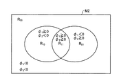
式(4)に示すエネルギー関数E(φ)におけるレベルセット関数φを、次式(12)に示すように2種類のレベルセット関数φ1、φ2に拡張する。この場合、式(5)、(6)はそれぞれ、次式(13)、(14)に変形される。
図15は、2種類のレベルセット関数における符号の組み合わせに応じて分類される4つの領域を示す模式図である。図15に示すように、処理対象の画像M2内の領域は、2種類のレベルセット関数φ1、φ2における符号の組み合わせに応じて、4つの領域R11(φ1≧0且つφ2≧0)、R10(φ1≧0且つφ2<0)、R01(φ1<0且つφ2≧0)、R00(φ1<0且つφ2<0)に分類することができる。各領域R11、R10、R01、R00に含まれる画素の画素値の面積平均c11、c10、c01、c00は、次式(15−1)〜(15−4)によって与えられる。
式(12)によって与えられるエネルギー関数E(φ1,φ2)が最小化されるようにレベルセット関数φ1及びφ2を更新すると、レベルセット関数φ1とφ2の符号の組み合わせに応じて分類される4つの領域R11、R10、R01、R00を用いて、4つの境界を示すことができる。これにより、HE染色が施された標本の画像を、核、血球、間質、及び上皮の4種類の領域に分類することができる。 Energy function E (phi 1, phi 2) given by Equation (12) when the updating level set function phi 1 and phi 2 to be minimized, the level set function phi 1 and phi 2 according to the combination of the code By using the four regions R 11 , R 10 , R 01 and R 00 classified as follows, four boundaries can be shown. As a result, the image of the specimen subjected to HE staining can be classified into four types of regions: nucleus, blood cell, stroma, and epithelium.
(変形例2)
次に、本発明の実施の形態1の変形例2について説明する。
上記実施の形態1においては、LSM法を用いて核領域と背景との境界を認識する方法を説明した。これに対してさらに、認識した境界をもとに、核領域と背景とに二値のラベルを付与することにより、画像内を二値化し、それによって得られた二値化画像から、核情報として核領域の慣性主軸方向を検出することができる。なお、二値化画像から形状の特徴を求める手法については、CG−ARTS協会、「ディジタル画像処理」第2版(2009年)、第182〜183頁も参照されたい。
(Modification 2)
Next, a second modification of the first embodiment of the present invention will be described.
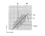
In the first embodiment, the method of recognizing the boundary between the nucleus region and the background using the LSM method has been described. On the other hand, based on the recognized boundary, binary labels are assigned to the core region and the background to binarize the image, and the binary information is obtained from the binarized image obtained thereby. As a result, the inertial principal axis direction of the nuclear region can be detected. For the method of obtaining the shape feature from the binarized image, see also CG-ARTS Association, “Digital Image Processing”, 2nd edition (2009), pages 182-183.
例えば図16に示すように、核領域が黒画素によって示された二値化画像M3が得られた場合、形状の特徴は、次式(16)に示すように、pq次モーメントM(p,q)によって与えられる。
式(16)において、符号i及びjはそれぞれ、画像内のX軸及びY軸において黒画素が存在する位置を示す。例えば、モーメントM(0,0)は、黒画素があったときに1が加算されるので、核領域Nuの面積を与える。また、M(1,0)は、X軸における1次モーメントであり、M(0,1)は、Y軸における1次モーメントである。従って、核領域Nuの重心(gX,gY)は、次式(17)によって与えられる。
さらに、核領域Nuの慣性主軸PAの方向を、重心(gX,gY)を通る直線とすると、次式(18)が成り立つ。
なお、核情報としては、核領域の慣性主軸PAの方向の代わりに、該慣性主軸PAと直交する方向を用いることもできる。或いは、該直交する方向以外にも、慣性主軸に対して所定の角度をなす方向を用いても良い。 As the nuclear information, a direction orthogonal to the inertial principal axis PA can be used instead of the direction of the inertial principal axis PA of the nucleus region. Or you may use the direction which makes a predetermined angle with respect to an inertial principal axis besides the orthogonal direction.
(実施の形態2)
次に、本発明の実施の形態2について説明する。
上記実施の形態1においては、LSM法等により繊維状組織の輪郭形状を推定し、該輪郭形状を評価する際に核情報を用いた。それに対し、本実施の形態2においては、繊維状組織の輪郭形状を推定する際に(図14のステップS122参照)核情報を用いる手法を説明する。なお、実施の形態2に係る画像処理装置及び画像処理方法は、全体として実施の形態1と同様である(図1及び図7参照)。
(Embodiment 2)
Next, a second embodiment of the present invention will be described.
In the first embodiment, the contour shape of the fibrous tissue is estimated by the LSM method or the like, and the nuclear information is used when evaluating the contour shape. On the other hand, in the second embodiment, a method of using nuclear information when estimating the contour shape of a fibrous tissue (see step S122 in FIG. 14) will be described. Note that the image processing apparatus and the image processing method according to the second embodiment are the same as those of the first embodiment as a whole (see FIGS. 1 and 7).
一般に、LSM法においては、画像中の画素が持つ情報として画素値(輝度値)を用いて演算が行われる。しかしながら、本実施の形態2においては、核領域に含まれる画素については、画素が持つ情報として、画素値(輝度値)の代わりに当該核領域の慣性主軸方向の情報を用いる。なお、慣性主軸方向の角度統計手法については、石原秀至、「角度データの統計処理基礎」、第4回定量生物学の会 チュートリアル(2012年1月7日)も参照されたい。 In general, in the LSM method, calculation is performed using a pixel value (luminance value) as information held by a pixel in an image. However, in the second embodiment, for the pixels included in the nucleus region, information on the inertial principal axis direction of the nucleus region is used instead of the pixel value (luminance value) as information held by the pixel. Please refer to Hidetoshi Ishihara, “Statistical Processing of Angle Data”, 4th Quantitative Biology Society Tutorial (January 7, 2012) for the statistical method of angle in the principal axis direction of inertia.
図17は、本発明の実施の形態2に係る画像処理方法を説明するための模式図である。例えば図17に示すように、処理対象の画像M4から複数の核領域Nunが検出され、各核領域Nunの慣性主軸方向の情報(直線の傾き)が算出された場合、組織認識部152は、各核領域Nunの重心位置に最も近い画素に、該慣性主軸方向の情報を付加する。慣性主軸方向の情報は、例えば、画像内の座標系(XY座標)における2次元ベクトルV(vX,vY)によって表される。なお、各ベクトルV(vX,vY)は、ベクトルの長さ√(vX 2+vY 2)が全ての核領域Nunの間で同じ長さとなるように予め規格化される。また、各領域Nunの重心位置に最も近い画素ではなく、該慣性主軸方向の情報を付加されなかった画素のベクトルV(vX,vY)の値は、(0,0)等の定数を代入しても良いし、近辺の画素が持つベクトルV(vX,vY)の値を用いて内挿、外挿、補間、又は推定をする、或いは、近辺の画素のベクトルV(vX,vY)にフィルタをかけた結果の値を代入するなどして求めても良い。内挿、外挿、補間、又は推定の方法としては、0次補間(最近傍補間、最近傍点補間)、線形補間(直線補間、1次補間)、放物線補間(2次補間)、多項式補間、キュービック補間(3次補間)、キュービックコンボリューション、ラグランジュ補間、スプライン補間、シンク関数を用いた補間、ランツォシュ補間、カーネル密度推定等が挙げられる。
FIG. 17 is a schematic diagram for explaining an image processing method according to the second embodiment of the present invention. For example, as shown in FIG. 17, when a plurality of nucleus regions Nu n are detected from the image M4 to be processed and the inertia principal axis information (straight line inclination) of each nucleus region Nu n is calculated, the
組織認識部152は、このように核領域Nunの慣性主軸方向の情報が付加された画像に対し、必要に応じて、ホワイトバランス処理、デモザイキング、色変換、濃度変換(ガンマ変換等)、平滑化(ノイズ除去等)、鮮鋭化(エッジ強調等)等の前処理(画像処理)を施した上で、LSM法を適用する。
The
上述したようなベクトル値を有する画素に対してLSM法を適用すると、慣性主軸方向(ベクトルV)が近い画素同士をまとめるように輪郭BFが認識される。ここで、繊維状組織内に含まれる核同士は互いに慣性主軸方向が近いので、このようにして認識された輪郭BFを繊維状組織の輪郭として認識することができる。従って、この手法を、実施の形態1と組み合わせることで、繊維状組織の認識性能をさらに向上させることもできる。
When the LSM method is applied to the pixels having the vector values as described above, the contour BF is recognized so that the pixels having the inertial principal axis directions (vector V) are close to each other. Here, since the nuclei contained in the fibrous tissue are close to each other in the principal axis direction of inertia, the contour BF recognized in this way can be recognized as the contour of the fibrous tissue. Therefore, by combining this method with
また、LSM法の他にも、認識した輪郭BF内に含まれる核領域Nunの慣性主軸方向(ベクトルV)の標準偏差や分散が小さくなるように輪郭BFを更新することで、輪郭BFを認識しても良い。或いは、慣性主軸方向の分布関数に基づいて決定される特徴に基づき、例えばエントロピーが最小化されるように輪郭BFを更新することで、輪郭BFを認識しても良い。 In addition to the LSM method, the contour BF is updated so that the standard deviation and variance in the inertial principal axis direction (vector V) of the nucleus region Nu n included in the recognized contour BF are reduced. BF may be recognized. Alternatively, the contour BF may be recognized by updating the contour BF so as to minimize the entropy, for example, based on characteristics determined based on the distribution function in the inertial principal axis direction.
なお、LSM法においては、計算を簡単にするために、実施の形態1における式(4)〜(6)を、次式(19)〜(21)のように変形しても良い。
このうち、式(21)における輝度値Iの代わりにベクトルVが代入される。この際、ベクトルVの和、差、及び平均は、角度統計に従ってベクトルとして算出される。また、絶対値はベクトルの長さとして算出される。 Of these, the vector V is substituted for the luminance value I in the equation (21). At this time, the sum, difference, and average of the vectors V are calculated as vectors according to the angle statistics. The absolute value is calculated as the length of the vector.
本実施の形態2においても、実施の形態1の変形例1と同様に、複数種類のレベルセット関数を用いてLSM法の演算を行っても良い。 Also in the second embodiment, similarly to the first modification of the first embodiment, the LSM method may be calculated using a plurality of types of level set functions.
(実施の形態3)
次に、本発明の実施の形態3について説明する。
本実施の形態3においては、繊維状組織の輪郭形状を推定する際に(図14のステップS122参照)、事前知識を用いる手法を説明する。なお、事前知識を用いた画像認識の手法については、フッセネガー(Fussenegger)等による「A Multiphase Level Set Based Segmentation Framework with Pose Invariant Shape Priors」(Computer Vision−ACCV 2006, Springer Berlin Heidelberg(2006年)、第395〜404頁)も参照されたい。また、実施の形態3に係る画像処理装置及び画像処理方法は、全体として実施の形態1と同様である(図1及び図7参照)。
(Embodiment 3)
Next, a third embodiment of the present invention will be described.
In the third embodiment, a method of using prior knowledge when estimating the contour shape of a fibrous tissue (see step S122 in FIG. 14) will be described. As for the image recognition method using prior knowledge, “A Multiphase Level Set Based Segmentation Framework with Pose Invariant Shape Priors” (Computer Vision-ACCV 2006, Springer Berlin Heidelberg (2006)) Pp. 395-404). The image processing apparatus and the image processing method according to the third embodiment are the same as those of the first embodiment as a whole (see FIGS. 1 and 7).
ここで、繊維状組織の断面における輪郭形状は、概ね円形又は楕円形をなしている。しかしながら、観察対象である生体標本の作成条件(染色法、切断面等)や顕微鏡における観察条件(検鏡法、倍率等)は観察の都度異なるため、事前知識として、楕円の大きさ、傾き、及び位置を予め指定することは困難である。そこで、本実施の形態3においては、事前知識として用いる楕円の情報に対し、拡大縮小、回転、移動の自由度を与えて繊維状組織の境界を認識する方法を説明する。 Here, the contour shape in the cross section of the fibrous tissue is generally circular or elliptical. However, the preparation conditions (staining method, cut surface, etc.) of the biological specimen to be observed and the observation conditions (microscopy method, magnification, etc.) in the microscope differ for each observation, so as prior knowledge, the size, inclination, And it is difficult to specify the position in advance. Therefore, in the third embodiment, a method of recognizing the boundary of the fibrous tissue by giving the ellipse information used as prior knowledge the degree of freedom of enlargement / reduction, rotation, and movement will be described.
まず、上述したエネルギー関数E(φ)の式(4)を、次式(22)のように変形する。
また、右辺の第3項Eshapeは、事前知識に関する項であり、次式(23)によって与えられる。
このようなエネルギー関数E(φ)を、最急降下法を用いて解くと、次式(25)が得られる。
ただし、倍率s、回転角θ、移動量Tは、次式(26)〜(28)に示す自己無撞着方程式に従って更新する。
これらの式(25)〜(28)によって得られるレベルセット関数φの輪郭C(図9参照)が、楕円形状の情報を事前知識として用いた場合における境界認識結果(即ち、繊維状組織の輪郭)を示す。 The contour C (see FIG. 9) of the level set function φ obtained by these equations (25) to (28) is the boundary recognition result (ie, the contour of the fibrous tissue) when the elliptical information is used as prior knowledge. ).
このように、繊維状組織の輪郭が楕円形状に近いと予測される場合には、事前知識を用いることで、輪郭の認識性能を向上させることができる。また、事前知識を用いる手法を他の実施の形態と組み合わせることで、輪郭の認識性能を向上させることもできる。事前知識の組み合わせ方法の例としては、上述したレベルセット関数として組み合わせる方法の他にも、事前知識をパラメータ、目標値、正解値、参照値、参考値、修正値、引数として用いる方法が挙げられる。また、事前知識を用いて形状を認識する手法は、ステップS11において核領域の形状を認識する際にも適用することができる。 Thus, when it is predicted that the contour of the fibrous tissue is close to an elliptical shape, the recognition performance of the contour can be improved by using prior knowledge. In addition, it is also possible to improve the contour recognition performance by combining a technique using prior knowledge with another embodiment. Examples of the prior knowledge combination method include a method of using prior knowledge as a parameter, target value, correct value, reference value, reference value, correction value, and argument in addition to the above-described level set function. . Moreover, the method of recognizing the shape using prior knowledge can also be applied when recognizing the shape of the nucleus region in step S11.
(変形例3)
次に、実施の形態3の変形例について説明する。
上記実施の形態3においては、演算子Aを構成する倍率s、回転角θ、及び移動量Tを、自己無撞着方程式に従って更新したが、このうちの回転角θについては、以下に説明する方法によって更新しても良い。
(Modification 3)
Next, a modification of the third embodiment will be described.
In the third embodiment, the magnification s, the rotation angle θ, and the movement amount T constituting the operator A are updated in accordance with the self-consistent equation. Of these, the rotation angle θ is a method described below. May be updated by
例えば、レベルセット関数φを更新する際のイタレーションごとに、レベルセット関数φの輪郭C内の核領域の慣性主軸方向(X軸からの回転角ω、図16参照)を算出し、該回転角ωの平均値と事前知識としての楕円の慣性主軸方向が一致するように、回転角θを更新させる。或いは、回転角ωの平均値と事前知識としての楕円の慣性主軸方向との差分が小さくなるように、回転角θを更新しても良い。それにより、輪郭C内の核領域の慣性主軸方向と、楕円形状を事前知識として認識した繊維状組織の輪郭の慣性主軸方向とを近づけることができる。このように、輪郭C内の核領域の慣性主軸方向と、繊維状組織の輪郭の慣性主軸方向とが近い場合、実施の形態3の変形例を他の実施の形態(例えば実施の形態1)と組み合わせることで、繊維状組織の認識性能を向上させることができる。 For example, for each iteration when updating the level set function φ, the inertial principal axis direction (rotation angle ω from the X axis, see FIG. 16) of the nucleus region in the contour C of the level set function φ is calculated, and the rotation The rotation angle θ is updated so that the average value of the angle ω matches the inertial principal axis direction of the ellipse as prior knowledge. Alternatively, the rotation angle θ may be updated so that the difference between the average value of the rotation angle ω and the inertial principal axis direction of the ellipse as prior knowledge becomes small. Thereby, the inertial principal axis direction of the nucleus region in the contour C can be brought close to the inertial principal axis direction of the contour of the fibrous tissue in which the elliptical shape is recognized as prior knowledge. Thus, when the inertial principal axis direction of the nucleus region in the contour C is close to the inertial principal axis direction of the contour of the fibrous tissue, the modification of the third embodiment is another embodiment (for example, the first embodiment). By combining with, the recognition performance of the fibrous tissue can be improved.
また、事前知識としての楕円の慣性主軸方向との比較対象として、回転角ωの平均値の代わりに、回転角ωの中央値、最頻値、尖度、歪度、エントロピー等の統計値や、分布関数そのものを用いても良い。 Also, as a comparison object with the inertial principal axis direction of the ellipse as prior knowledge, instead of the average value of the rotation angle ω, statistical values such as the median value, mode value, kurtosis, skewness, entropy of the rotation angle ω Alternatively, the distribution function itself may be used.
このような回転角θの更新方法も、事前知識を用いて核領域の形状を認識する際に適用することができる。 Such a method of updating the rotation angle θ can also be applied when recognizing the shape of the nucleus region using prior knowledge.
(実施の形態4)
次に、本発明の実施の形態4について説明する。
図18は、本実施の形態4に係る顕微鏡システムの構成を示す図である。図18に示すように、本実施の形態4に係る顕微鏡システムは、画像処理装置10と、生体から採取した組織標本の拡大像を生成する顕微鏡装置20と、該顕微鏡装置20が生成した拡大像を撮像することにより画像データを生成して画像処理装置10に入力する撮像部30とを備える。
(Embodiment 4)
Next, a fourth embodiment of the present invention will be described.
FIG. 18 is a diagram illustrating a configuration of a microscope system according to the fourth embodiment. As shown in FIG. 18, the microscope system according to the fourth embodiment includes an
図18に示すように、顕微鏡装置20は、略C字形のアーム200と、該アーム200上に三眼鏡筒ユニット201を介して支持された鏡筒202及び接眼レンズユニット203と、アーム200に設けられた落射照明ユニット210及び透過照明ユニット220と、組織標本Sが載置されるステージ231を含む電動ステージユニット230と、鏡筒202の一端側に三眼鏡筒ユニット201を介してステージ231と対向するように設けられ、組織標本Sからの観察光を結像する対物レンズ240とを備える。
As shown in FIG. 18, the
三眼鏡筒ユニット201は、対物レンズ240から入射した観察光を、ユーザが組織標本Sを直接観察するための接眼レンズユニット203と、後述する撮像部30との方向に分岐する。
The
落射照明ユニット210は、落射照明用光源211及び落射照明光学系212を備え、組織標本Sに対して落射照明光を照射する。落射照明光学系212は、落射照明用光源211から出射した照明光を集光して、観察光学系204の光軸Lの方向に導く種々の光学部材(フィルタユニット、シャッタ、視野絞り、開口絞り等)を含む。
The epi-
透過照明ユニット220は、透過照明用光源221及び透過照明光学系222を備え、組織標本Sに対して透過照明光を照射する。透過照明光学系222は、透過照明用光源221から出射した照明光を集光して光軸Lの方向に導く種々の光学部材(フィルタユニット、シャッタ、視野絞り、開口絞り等)を含む。
The transmitted
これらの落射照明ユニット210及び透過照明ユニット220は、検鏡法に応じていずれかが選択されて使用される。なお、顕微鏡装置20に、落射照明ユニット210と透過照明ユニット220とのいずれか一方のみを設けることとしても良い。
Either one of the epi-
電動ステージユニット230は、ステージ231と、該ステージ231を駆動させるステージ駆動部232とを備える。ステージ駆動部232は、例えばモータによって構成され、ステージ231を光軸Lと直交する面内(即ちxy平面内)において移動させる。また、ステージ駆動部232は、ステージ231をz軸に沿って移動させることにより、対物レンズ240を組織標本Sに対して合焦させる。なお、ステージ駆動部232の代わりに調節ツマミ等を用いて、ユーザがステージ231を手動で移動させる構成としても良い。
The
対物レンズ240は、倍率が互いに異なる複数の対物レンズ(例えば、対物レンズ240、241)を保持可能なレボルバ242に取り付けられている。レボルバ242を回転させ、ステージ231と対向する対物レンズ240、241を変更することにより、撮像倍率を変化させることができる。
The
撮像部30は、例えばCCDやCMOS等からなる撮像素子31を備え、撮像素子31が備える各画素においてR(赤)、G(緑)、B(青)の各バンドにおける画素レベル(画素値)を持つカラー画像を撮像可能なカメラを用いて構成される。撮像部30は、観察光学系204(鏡筒202)の一端に設けられ、観察光学系204を介して撮像素子31の受光面に入射した観察光を光電変換することにより、観察光学系204の視野に対応する画像を表す画像データを生成し、画像処理装置10の画像取得部12(図1参照)に入力する。
The
以上説明した実施の形態1〜4及びこれらの変形例はそのままに限定されるものではなく、各実施の形態1〜4及びこれらの変形例に開示されている複数の構成要素を適宜組み合わせることによって、種々の発明を形成することができる。例えば、実施の形態に示される全構成要素からいくつかの構成要素を除外して形成しても良い。或いは、異なる実施の形態に示した構成要素を適宜組み合わせて形成しても良い。
10 画像処理装置
11 入力部
12 画像取得部
13 出力部
14 記憶部
15 演算部
16 制御部
17 表示装置
151 単一核認識部
151a 核形状認識部
151b 核情報生成部
152 組織認識部
152a 統計値算出部
152b 組織形状認識部
20 顕微鏡装置
200 アーム
201 三眼鏡筒ユニット
202 鏡筒
203 接眼レンズユニット
204 観察光学系
210 落射照明ユニット
211 落射照明用光源
212 落射照明光学系
220 透過照明ユニット
221 透過照明用光源
222 透過照明光学系
230 電動ステージユニット
231 ステージ
232 ステージ駆動部
240、241 対物レンズ
242 レボルバ
30 撮像部
31 撮像素子
DESCRIPTION OF
Claims (13)
前記画像に写った所定の細胞小器官の形状を個別に認識する細胞小器官認識部と、
前記所定の細胞小器官の形状に基づいて、前記画像に写った繊維状組織又は管状組織の形状を認識する組織認識部と、
を備えることを特徴とする画像処理装置。 An image acquisition unit for acquiring an image of a tissue specimen collected from a living body;
An organelle recognition unit that individually recognizes the shape of a predetermined organelle reflected in the image;
A tissue recognition unit for recognizing the shape of a fibrous tissue or tubular tissue reflected in the image based on the shape of the predetermined organelle;
An image processing apparatus comprising:
前記画像を構成する各画素が前記所定の細胞小器官を表す画素であるか否かを判定し、前記所定の細胞小器官を表すと判定された画素の領域である細胞小器官領域の形状を認識する細胞小器官形状認識部と、
前記細胞小器官領域の形状を定量化した情報である細胞小器官情報を生成する細胞小器官情報生成部と、
を備えることを特徴とする請求項1に記載の画像処理装置。 The organelle recognition unit is
It is determined whether each pixel constituting the image is a pixel representing the predetermined organelle, and the shape of the organelle region that is a region of the pixel determined to represent the predetermined organelle is determined. An organelle shape recognition unit for recognizing;
An organelle information generating unit that generates organelle information that is information obtained by quantifying the shape of the organelle region;
The image processing apparatus according to claim 1, further comprising:
前記画像から抽出された複数の前記細胞小器官領域についてそれぞれ生成された前記細胞小器官情報の統計情報を算出する統計情報算出部と、
前記統計情報算出部により算出された前記統計情報に基づいて、前記繊維状組織又は前記管状組織の形状を認識する組織形状認識部と、
を備えることを特徴とする請求項2〜4のいずれか1項に記載の画像処理装置。 The tissue recognition unit
A statistical information calculation unit that calculates statistical information of the organelle information generated for each of the plurality of organelle regions extracted from the image;
Based on the statistical information calculated by the statistical information calculation unit, a tissue shape recognition unit for recognizing the shape of the fibrous tissue or the tubular tissue,
The image processing apparatus according to claim 2, further comprising:
ことを特徴とする請求項5又は6に記載の画像処理装置。 The tissue shape recognition unit estimates the shape of the fibrous tissue or the tubular tissue in the image, and calculates the statistical information and the shape information obtained by quantifying the estimated shape of the fibrous tissue or the tubular tissue. Recognizing the shape of the fibrous tissue or the tubular tissue by comparing the calculation result of the statistical information calculated by the unit,
The image processing apparatus according to claim 5, wherein the image processing apparatus is an image processing apparatus.
生体から採取した組織標本の拡大像を生成する顕微鏡装置と、
前記拡大像を撮像することにより画像データを生成して前記画像取得部に入力する撮像部と、
を備えることを特徴とする顕微鏡システム。 The image processing apparatus according to any one of claims 1 to 10,
A microscope device for generating an enlarged image of a tissue specimen collected from a living body;
An imaging unit that generates image data by capturing the magnified image and inputs the image data to the image acquisition unit;
A microscope system comprising:
演算部が、画像データを読み込むことにより前記画像を取得する画像取得ステップと、
前記演算部が、前記画像に写った所定の細胞小器官の形状を個別に認識する細胞小器官認識ステップと、
前記演算部が、前記所定の細胞小器官の形状に基づいて、前記画像に写った繊維状組織又は管状組織の形状を認識する組織認識ステップと、
を含むことを特徴とする画像処理方法。 In an image processing method executed by an image processing apparatus that processes an image of a tissue specimen collected from a living body,
An image acquisition step in which the calculation unit acquires the image by reading image data;
The organelle recognition step for individually recognizing the shape of a predetermined organelle shown in the image by the calculation unit;
The tissue recognition step for recognizing the shape of the fibrous tissue or tubular tissue shown in the image based on the shape of the predetermined organelle,
An image processing method comprising:
前記画像に写った所定の細胞小器官の形状を個別に認識する細胞小器官認識ステップと、
前記所定の細胞小器官の形状に基づいて、前記画像に写った繊維状組織又は管状組織の形状を認識する組織認識ステップと、
をコンピュータに実行させることを特徴とする画像処理プログラム。 An image acquisition step of acquiring an image of a tissue specimen collected from a living body;
Organelle recognition step for individually recognizing the shape of a predetermined organelle shown in the image,
A tissue recognition step for recognizing the shape of a fibrous tissue or tubular tissue shown in the image based on the shape of the predetermined organelle;
An image processing program for causing a computer to execute.
Priority Applications (1)
| Application Number | Priority Date | Filing Date | Title |
|---|---|---|---|
| JP2013255413A JP2015114172A (en) | 2013-12-10 | 2013-12-10 | Image processing apparatus, microscope system, image processing method, and image processing program |
Applications Claiming Priority (1)
| Application Number | Priority Date | Filing Date | Title |
|---|---|---|---|
| JP2013255413A JP2015114172A (en) | 2013-12-10 | 2013-12-10 | Image processing apparatus, microscope system, image processing method, and image processing program |
Publications (1)
| Publication Number | Publication Date |
|---|---|
| JP2015114172A true JP2015114172A (en) | 2015-06-22 |
Family
ID=53528099
Family Applications (1)
| Application Number | Title | Priority Date | Filing Date |
|---|---|---|---|
| JP2013255413A Pending JP2015114172A (en) | 2013-12-10 | 2013-12-10 | Image processing apparatus, microscope system, image processing method, and image processing program |
Country Status (1)
| Country | Link |
|---|---|
| JP (1) | JP2015114172A (en) |
Cited By (8)
| Publication number | Priority date | Publication date | Assignee | Title |
|---|---|---|---|---|
| WO2016152242A1 (en) * | 2015-03-25 | 2016-09-29 | 株式会社日立ハイテクノロジーズ | Cytodiagnosis assistance device, cytodiagnosis assistance method, remote diagnosis assistance system, service provision system, and image processing method |
| JP2020092941A (en) * | 2018-12-14 | 2020-06-18 | キヤノンメディカルシステムズ株式会社 | Ultrasonic diagnostic device, medical information processing device, medical information processing program |
| CN111445490A (en) * | 2020-02-21 | 2020-07-24 | 于兴虎 | Method and system for extracting target foreground of micro-operation system |
| JP2021152463A (en) * | 2020-03-24 | 2021-09-30 | 株式会社ブレイン | Diagnosis support method and system thereof |
| JP2021533505A (en) * | 2018-12-29 | 2021-12-02 | ベイジン センスタイム テクノロジー デベロップメント カンパニー, リミテッド | Deep model training methods and their equipment, electronics and storage media |
| JP2023010124A (en) * | 2021-07-09 | 2023-01-20 | 横河電機株式会社 | Determination device, determination method, and determination program |
| WO2023136240A1 (en) | 2022-01-11 | 2023-07-20 | Jfeスチール株式会社 | Information processing method, information processing device, information processing system, information processing program, and sintered ore production method |
| CN117611654A (en) * | 2024-01-24 | 2024-02-27 | 深圳市爱贝科精密工业股份有限公司 | A spindle thermal elongation testing method and testing device |
-
2013
- 2013-12-10 JP JP2013255413A patent/JP2015114172A/en active Pending
Cited By (16)
| Publication number | Priority date | Publication date | Assignee | Title |
|---|---|---|---|---|
| US10453192B2 (en) | 2015-03-25 | 2019-10-22 | Hitachi High-Technologies Corporation | Cytologic diagnosis support apparatus, cytologic diagnosis support method, remote diagnosis support system, service providing system, and image processing method |
| WO2016152242A1 (en) * | 2015-03-25 | 2016-09-29 | 株式会社日立ハイテクノロジーズ | Cytodiagnosis assistance device, cytodiagnosis assistance method, remote diagnosis assistance system, service provision system, and image processing method |
| US11712219B2 (en) | 2018-12-14 | 2023-08-01 | Canon Medical Systems Corporation | Ultrasonic wave diagnostic apparatus, medical information processing apparatus, and computer program product |
| JP2020092941A (en) * | 2018-12-14 | 2020-06-18 | キヤノンメディカルシステムズ株式会社 | Ultrasonic diagnostic device, medical information processing device, medical information processing program |
| JP7258538B2 (en) | 2018-12-14 | 2023-04-17 | キヤノンメディカルシステムズ株式会社 | Ultrasound diagnostic equipment, medical information processing equipment, medical information processing program |
| JP2021533505A (en) * | 2018-12-29 | 2021-12-02 | ベイジン センスタイム テクノロジー デベロップメント カンパニー, リミテッド | Deep model training methods and their equipment, electronics and storage media |
| JP7158563B2 (en) | 2018-12-29 | 2022-10-21 | ベイジン・センスタイム・テクノロジー・デベロップメント・カンパニー・リミテッド | Deep model training method and its device, electronic device and storage medium |
| CN111445490A (en) * | 2020-02-21 | 2020-07-24 | 于兴虎 | Method and system for extracting target foreground of micro-operation system |
| CN111445490B (en) * | 2020-02-21 | 2023-10-20 | 于兴虎 | A method and system for extracting target foreground of microscopic operating system |
| JP2021152463A (en) * | 2020-03-24 | 2021-09-30 | 株式会社ブレイン | Diagnosis support method and system thereof |
| JP7473893B2 (en) | 2020-03-24 | 2024-04-24 | 株式会社ブレイン | Diagnostic support method and system thereof |
| JP2023010124A (en) * | 2021-07-09 | 2023-01-20 | 横河電機株式会社 | Determination device, determination method, and determination program |
| JP7635661B2 (en) | 2021-07-09 | 2025-02-26 | 横河電機株式会社 | Determination device, determination method, and determination program |
| WO2023136240A1 (en) | 2022-01-11 | 2023-07-20 | Jfeスチール株式会社 | Information processing method, information processing device, information processing system, information processing program, and sintered ore production method |
| CN117611654A (en) * | 2024-01-24 | 2024-02-27 | 深圳市爱贝科精密工业股份有限公司 | A spindle thermal elongation testing method and testing device |
| CN117611654B (en) * | 2024-01-24 | 2024-04-16 | 深圳市爱贝科精密工业股份有限公司 | Spindle thermal elongation testing method and testing device |
Similar Documents
| Publication | Publication Date | Title |
|---|---|---|
| JP7422825B2 (en) | Focus-weighted machine learning classifier error prediction for microscope slide images | |
| JP2015114172A (en) | Image processing apparatus, microscope system, image processing method, and image processing program | |
| Smal et al. | Particle filtering for multiple object tracking in dynamic fluorescence microscopy images: Application to microtubule growth analysis | |
| JP6791245B2 (en) | Image processing device, image processing method and image processing program | |
| JP2022506135A (en) | Segmentation of 3D intercellular structures in microscopic images using iterative deep learning flows that incorporate human contributions | |
| Sbalzarini | Seeing is believing: quantifying is convincing: computational image analysis in biology | |
| CN112348059A (en) | Deep learning-based method and system for classifying multiple dyeing pathological images | |
| WO2017150194A1 (en) | Image processing device, image processing method, and program | |
| WO2021150973A1 (en) | Intelligent automated imaging system | |
| CN110736747A (en) | cell liquid based smear under-mirror positioning method and system | |
| CN114926357B (en) | Self-correction method of LED array light source position in computational microscopy imaging system | |
| CN111369553A (en) | Sample slide scanning and image processing method and digital microscope system | |
| Kanwal et al. | Quantifying the effect of color processing on blood and damaged tissue detection in whole slide images | |
| Kromp et al. | Deep Learning architectures for generalized immunofluorescence based nuclear image segmentation | |
| Roudot et al. | u-track 3D: measuring and interrogating dense particle dynamics in three dimensions | |
| WO2023204959A1 (en) | Cell classification using center emphasis of a feature map | |
| WO2021067507A1 (en) | Building computational transfer functions on 3d light microscopy images using deep learning | |
| JP2023537978A (en) | Active learning system for digital pathology | |
| US20200074628A1 (en) | Image processing apparatus, imaging system, image processing method and computer readable recoding medium | |
| JP2013113818A (en) | Image processing device, microscope system, image processing method and image processing program | |
| EP4202523A1 (en) | System, method and computer program for a surgical microscope system and corresponding surgical microscope system | |
| JP2025535808A (en) | Quality control of in vitro analytical sample output | |
| WO2015089564A1 (en) | Thickness estimation for microscopy | |
| JP2022023322A (en) | Charged particle beam device and charge evaluation method | |
| CN112069735A (en) | Full-slice digital imaging high-precision automatic focusing method based on asymmetric aberration |


