JP2015113563A - Screw pile and burying method thereof - Google Patents
Screw pile and burying method thereof Download PDFInfo
- Publication number
- JP2015113563A JP2015113563A JP2013253967A JP2013253967A JP2015113563A JP 2015113563 A JP2015113563 A JP 2015113563A JP 2013253967 A JP2013253967 A JP 2013253967A JP 2013253967 A JP2013253967 A JP 2013253967A JP 2015113563 A JP2015113563 A JP 2015113563A
- Authority
- JP
- Japan
- Prior art keywords
- pile
- hole
- spiral
- central
- tip
- Prior art date
- Legal status (The legal status is an assumption and is not a legal conclusion. Google has not performed a legal analysis and makes no representation as to the accuracy of the status listed.)
- Pending
Links
Images


Abstract
Description
本発明は、螺旋杭および埋設方法に関する。 The present invention relates to a spiral pile and a burying method.
近年、太陽光発電システムが各地に建設されている。従来は、太陽電池パネルを設置する架台を固定するために、地面を掘削してコンクリートを打設することで基礎を作っていた。これに代わり、作業を容易にし、工期を短縮するために、螺旋杭(スパイラル杭)を地中に直接打ち込み、螺旋杭に架台を固定する方法がある(特許文献1参照)。 In recent years, solar power generation systems have been built in various places. Conventionally, in order to fix a platform on which a solar cell panel is installed, a foundation is made by excavating the ground and placing concrete. Instead of this, in order to facilitate the work and shorten the construction period, there is a method in which a spiral pile (spiral pile) is directly driven into the ground and a gantry is fixed to the spiral pile (see Patent Document 1).
また、螺旋杭の側面の透孔から土中にモルタルを圧出し、モルタル塊を形成することで埋設支持力を増強する方法が提案されている(特許文献2参照)。 In addition, a method has been proposed in which mortar is pressed into the soil from the through-holes on the side surfaces of the spiral pile and mortar lumps are formed to enhance the embedding support force (see Patent Document 2).
太陽電池パネルは、入射光に対して受光面をできるだけ垂直にするように設置するのが望ましいので、水平に対して30°程度傾斜させて設置することが一般的になっている。この傾斜角度によって、横風が太陽電池パネルを鉛直上方向に持ち上げるように作用する。強い横風が吹くと大きな力が鉛直上方向に働き、螺旋杭の支持力を超えて、螺旋杭が抜けてしまうことが問題になっている。螺旋杭の側面にモルタル塊を形成するようにした場合、埋設支持力は増強されるが、モルタル塊は螺旋杭の周囲付近に形成されるだけなので、鉛直上方向に働く力に弱い。 Since it is desirable to install the solar cell panel so that the light receiving surface is as vertical as possible with respect to the incident light, it is generally installed with an inclination of about 30 ° with respect to the horizontal. By this inclination angle, the cross wind acts to lift the solar cell panel vertically upward. When a strong crosswind blows, a large force works vertically upward, exceeding the support capacity of the spiral pile, causing the spiral pile to fall out. When the mortar lump is formed on the side surface of the spiral pile, the embedding support force is enhanced, but the mortar lump is only formed in the vicinity of the periphery of the spiral pile, so it is weak against the force acting in the vertical upward direction.
本発明は上記した事情のもとで考え出されたものであって、支持力をより大きくすることができる螺旋杭を提供することをその目的としている。 The present invention has been conceived under the circumstances described above, and an object of the present invention is to provide a spiral pile capable of increasing the supporting force.
上記課題を解決するため、本発明では、次の技術的手段を講じている。 In order to solve the above problems, the present invention takes the following technical means.
本発明の第1の側面によって提供される螺旋杭は、先端が略円錐尖端形状で、内部に空洞部を有する杭本体と、前記杭本体の先端側の外周に螺旋状に設けられた螺旋板と、前記杭本体の側面に設けられており、前記空洞部につながる透孔と、土壌を固結させるための流動体を、前記空洞部に注入するための注入部とを備える中心杭と、前記中心杭の側面から突出可能に配置される突出部材とを備えており、前記突出部材にも、前記空洞部につながる透孔が設けられていることを特徴とする。 The spiral pile provided by the first aspect of the present invention includes a pile main body having a substantially conical tip shape and a hollow portion inside, and a spiral plate provided spirally on the outer periphery of the pile main body on the tip end side. And a central pile provided on a side surface of the pile body, including a through hole connected to the cavity, and a fluid for solidifying soil, and an injection part for injecting the cavity into the cavity, And a projecting member arranged to project from the side surface of the central pile, and the projecting member is also provided with a through hole connected to the cavity.
本発明の好ましい実施の形態において、前記突出部材は、前記中心杭と同様の形状であり、前記中心杭の後端に設けられた開口部から挿入されて、前記中心杭の側面に設けられた孔から、前記中心杭の先端側に向かって突出する。 In preferable embodiment of this invention, the said protrusion member is the same shape as the said center pile, It was inserted from the opening part provided in the rear end of the said center pile, and was provided in the side surface of the said center pile. It protrudes toward the front end side of the central pile from the hole.
本発明の好ましい実施の形態において、前記突出部材が複数設けられている。 In a preferred embodiment of the present invention, a plurality of the protruding members are provided.
本発明の好ましい実施の形態において、前記流動体は、セメントミルクである。 In a preferred embodiment of the present invention, the fluid is cement milk.
本発明の第2の側面によって提供される埋設方法は、先端が略円錐尖端形状で内部に空洞部を有する杭本体と、前記杭本体の先端側の外周に螺旋状に設けられた螺旋板と、前記杭本体の側面に設けられており前記空洞部につながる透孔とを備える中心杭を、中心軸の周方向に回転させることで地中に埋設する第1の工程と、前記空洞部につながる透孔が設けられている突出部材を、前記中心杭の側面に設けられた孔から突出させる第2の工程と、土壌を固結させるための流動体を、前記空洞部に注入することで、前記各透孔から地中に吐出させる第3の工程とを備えていることを特徴とする。 The embedding method provided by the second aspect of the present invention includes a pile main body having a substantially conical pointed tip and a hollow portion therein, and a spiral plate spirally provided on the outer periphery on the tip side of the pile main body. A first step of burying a central pile provided on a side surface of the pile body and having a through hole connected to the hollow portion in the ground by rotating in a circumferential direction of a central axis; and By injecting into the cavity the second step of projecting the projecting member provided with the connecting through hole from the hole provided in the side surface of the central pile and the fluid for solidifying the soil. And a third step of discharging into the ground from each through hole.
本発明の好ましい実施の形態において、前記突出部材は前記中心杭と同様の形状であり、前記第2の工程は、前記中心杭の後端に設けられた開口部から前記突出部材を挿入する第4の工程と、前記突出部材を中心軸の周方向に回転させることで、前記中心杭の側面に設けられた孔から前記中心杭の先端側に向かって、地中に埋設させる第5の工程とを備えている。
In a preferred embodiment of the present invention, the protruding member has the same shape as the central pile, and the second step is a step of inserting the protruding member through an opening provided at a rear end of the central pile.
本発明によると、本発明に係る螺旋杭が埋設され、土壌を固結させるための流動体が空洞部に注入されると、当該流動体が中心杭の透孔から地中に吐出される。地中に吐出された流動体は、土壌を固結させて、中心杭と一体となった固結塊を形成する。また、当該流動体は、中心杭の側面から突出された突出部材の透孔からも地中に吐出される。したがって、形成される固結塊は、中心杭の側面方向に広がったものになる。これにより、螺旋杭の支持力をより大きくすることができる。 According to the present invention, when the spiral pile according to the present invention is embedded and a fluid for solidifying the soil is injected into the cavity, the fluid is discharged from the through hole of the central pile into the ground. The fluid discharged into the ground consolidates the soil and forms a consolidated mass integrated with the central pile. Moreover, the said fluid is discharged in the ground also from the through-hole of the protrusion member protruded from the side surface of the center pile. Therefore, the formed solid lump is expanded in the lateral direction of the central pile. Thereby, the support force of a spiral pile can be enlarged more.
本発明のその他の特徴および利点は、添付図面を参照して以下に行う詳細な説明によって、より明らかとなろう。 Other features and advantages of the present invention will become more apparent from the detailed description given below with reference to the accompanying drawings.
以下、本発明の実施の形態を、図面を参照して具体的に説明する。 Embodiments of the present invention will be specifically described below with reference to the drawings.
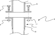
図1は、第1実施形態に係る螺旋杭Aを説明するための外観斜視図である。螺旋杭Aは、地中に埋設されて、例えば太陽電池パネルの架台などを固定するためのものである。螺旋杭Aは、第一杭1、第二杭2、および、ボルト3を備えている。
図2(a)は、第一杭1を説明するためのものであり、図1に示すII−II線に沿う断面図である。第一杭1は、杭本体10、開口部11、空洞部12、螺旋板13、透孔14、第二杭用孔15、および、ボルト用孔16を備えている。第一杭1は、本発明に係る「中心杭」の一例である。
Fig.2 (a) is for demonstrating the
杭本体10は、第一杭1の本体であり、先端が円錐尖端形状で、後端に開口部11が設けられた筒形状をなす。杭本体10は、鋼管の一端を円錐状に絞って閉止することで形成される。なお、杭本体10の製法は限定されず、鋼管の一端に円錐形状の部材を固着するようにして形成してもよいし、板材を円錐形状に溶接して形成してもよい。杭本体10の内部には、開口部11につながる空洞部12が設けられている。
The pile
螺旋板13は、杭本体10の先端側の外周に螺旋状に設けられた鋼板であり、杭本体10にねじ山を形成している(図1参照)。これにより、第一杭1の先端を地中に向けて、第一杭1の中心軸の周方向(図1の場合、時計回り)に回転させることで、第一杭1が先端方向に進んで、地中に埋設される。本実施形態では、杭本体10の先端から約半分の長さの位置まで、螺旋板13を設けている。なお、螺旋板13を設ける位置は限定されず、より先端に近い位置までだけ設けるようにしてもよいし、第二杭用孔15の手前まで設けるようにしてもよい。
The
なお、杭本体10および螺旋板13の材質は限定されず、ステンレスやアルミニウムであってもよい。また、金属に限定されず、プラスチックやセラミックであってもよい。
In addition, the material of the pile
透孔14は、杭本体10の側面に設けられた複数の孔であり、空洞部12につながっている。透孔14は、螺旋板13に沿って等間隔に配置されている(図1参照)。なお、透孔14の数および配置される位置は限定されない。例えば、杭本体10の先端付近にも配置するようにしてもよいし、第二杭用孔15の手前まで配置するようにしてもよい。また、透孔14を均等に配置する必要もなく、杭本体10の先端側により密集させるように配置してもよい。
The through
第二杭用孔15は、第二杭2を突出させるための孔であり、空洞部12につながっている。第二杭用孔15は、杭本体10の側面の後端部寄りに2つ、対向するように配置されている。第二杭用孔15は、用いられる第二杭2の数に合わせて設けられる。本実施形態では、2つの第二杭2を用いるため、第二杭用孔15が2つ設けられている。なお、第二杭用孔15の配置される位置は限定されない。例えば、杭本体10のより先端側に配置するようにしてもよいし、後端側に配置するようにしてもよい。また、設ける数に応じて配置位置を適宜決定すればよい。
The
ボルト用孔16は、ボルト3を通すための孔であり、空洞部12につながっている。ボルト用孔16は、杭本体10の側面の後端部付近に等間隔に4つ配置されている。ボルト用孔16は、用いられるボルト3の数に合わせて設けられる。本実施形態では、4つのボルト3を用いるため、ボルト用孔16が4つ設けられている。なお、ボルト用孔16の配置される位置は限定されないが、第一杭1を地中に埋設したときに地上に出る部分に配置する必要がある。
The
図2(b)は、第二杭2を説明するためのものであり、同図(a)と同様の断面図である。第二杭2は、第一杭1を地中に埋設した後、第一杭の開口部11から挿入されて、第二杭用孔15から第一杭1の先端方向に向けて、地中に埋設されるものである。第二杭2は、第一杭1を小さくしたものであり、杭本体20、開口部21、空洞部22、螺旋板23、および、透孔24を備えている。第二杭2は、本発明に係る「突出部材」の一例である。
FIG.2 (b) is for demonstrating the
杭本体20は、第二杭2の本体であり、先端が円錐尖端形状で、後端に開口部21が設けられた筒形状をなす。杭本体20は、鋼管の一端を円錐状に絞って閉止することで形成される。なお、杭本体20の製法は限定されない。杭本体20の内部には、開口部21につながる空洞部22が設けられている。
The pile
螺旋板23は、杭本体20の先端側の外周に螺旋状に設けられた鋼板であり、杭本体20にねじ山を形成している(図1参照)。これにより、第二杭2の先端を第一杭1の第二杭用孔15から地中に向けて、第二杭2の中心軸の周方向(図1の場合、時計回り)に回転させることで、第二杭2が先端方向に進んで、地中に埋設される。本実施形態では、杭本体20の先端から約半分の長さの位置まで、螺旋板23を設けている。なお、螺旋板23を設ける位置は限定されない。また、杭本体20および螺旋板23の材質は限定されない。
The
透孔24は、杭本体20の側面に設けられた複数の孔であり、空洞部22につながっている。透孔24は、螺旋板23に沿って等間隔に配置されている(図1参照)。なお、透孔24の数および配置される位置は限定されない。第二杭2を第一杭1の第二杭用孔15から突出させたとき(図1参照)、第二杭2の空洞部22が第一杭1の空洞部12とつながるので、各透孔24も第一杭1の空洞部12とつながる。
The through holes 24 are a plurality of holes provided in the side surface of the
ボルト3は、第一杭1の開口部11から挿入された支柱B(図3(d)参照)を固定するものである。本実施形態では、4つのボルト3を用いて支柱Bを固定する。なお、固定に用いるボルトの数はこれに限られない。
The
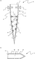
次に、図3を参照して、螺旋杭Aの埋設方法を説明する。 Next, a method for burying the spiral pile A will be described with reference to FIG.
図3(a)は、第一杭1を地中に埋設した状態を示している。第一杭1は、第二杭用孔15の上(後端側)まで埋設されている。第一杭1は、先端部を地面に向けて、第一杭1の中心軸が地面に対して略垂直になるようにして、中心軸の周方向に回転させることで、地中に埋設される。第一杭1の埋設は、小型の杭打ち機によって行ってもよいし、杭打ち用の工具を用いて人力で行ってもよい。なお、螺旋杭Aを建物の支柱を固定するために用いるのであれば、螺旋杭Aの大きさも大きくなるので、この場合は、第一杭1の埋設を建設用の杭打ち機で行うようにすればよい。なお、第一杭1は、必ずしも地面に対して略垂直に埋設する必要はない。例えば、地面が傾斜している場合は、地面に対して傾斜させて埋設してもよい。
Fig.3 (a) has shown the state which embed | buried the
図3(b)は、一方の第二杭2(図の左側)を地中に埋設し、他方の第二杭2(図の右側)の先端を地中に突き刺した状態を示している。各第二杭2は、第一杭1の開口部11から挿入されて、第二杭用孔15から第一杭1の先端方向に向けて、地中に埋設される。第二杭2は、先端部を第二杭用孔15に露出している地面に向けて、第二杭2の中心軸の周方向に回転させることで、地中に埋設される。第二杭2の埋設も、小型の杭打ち機によって行ってもよいし、杭打ち用の工具を用いて人力で行ってもよい。また、建設用の杭打ち機で行ってもよい。
FIG.3 (b) has shown the state which embed | buried one 2nd pile 2 (left side of a figure) in the ground, and pierced the front-end | tip of the other 2nd pile 2 (right side of a figure) in the ground. Each
図3(c)は、両方の第二杭2が地中に埋設され、第一杭1の開口部11から空洞部12にセメントミルク4を注入している状態を示している。セメントミルク4は、セメントと水とを練り混ぜてできたミルク状のものである。セメントミルク4は、開口部11に取り付けたパイプを介して、図示しない液体圧送装置によって加圧されて注入される。なお、本実施形態では、セメントミルクを注入しているが、これに限られない。地中に吐出されて、土壌を固結させるものであればよく、例えば、モルタルや水ガラス、その他の固結剤などでもよい。加圧して土壌に浸透させるので、粘度の低い液体が望ましく、セメントミルクが適している。図3(c)では、空洞部12に注入されたセメントミルク4が、第一杭1の先端側の透孔14から地中に吐出されている。
FIG. 3C shows a state in which both the
図3(d)は、適量のセメントミルク4を注入した後、注入を停止し、開口部11から支柱Bを挿入してボルト3で固定した状態を示している。図3(d)では、空洞部12に注入されたセメントミルク4が、第一杭1の透孔14および第二杭2の透孔24から地中に吐出されて土壌を固結させ、第一杭1および第二杭2と一体となった固結塊4’を形成している。
FIG. 3 (d) shows a state in which, after injecting an appropriate amount of
本実施形態において、螺旋杭Aが埋設され、セメントミルク4が空洞部12に注入されると、セメントミルク4が第一杭1の透孔14から地中に吐出される。また、セメントミルク4は、空洞部12から第二杭2の空洞部22に注入され、透孔24からも地中に吐出される。地中に吐出されたセメントミルク4は、土壌を固結させて、第一杭1および第二杭2と一体となった固結塊4’を形成する。第二杭2は、第一杭1の側面に設けられた第二杭用孔15から地中に突出するように埋設されている。したがって、固結塊4’は、第一杭1の側面側に広がった形に形成される。これにより、螺旋杭Aの支持力を従来の螺旋杭より大きくすることができる。
In the present embodiment, when the spiral pile A is embedded and the
螺旋杭Aに太陽電池パネルの架台の支柱を固定した場合、固結塊4’によって螺旋杭Aは、鉛直上方向に働く力に対する支持力が従来の螺旋杭より大きくなっているので、強い横風によって太陽電池パネルに鉛直上方向の大きな力が働いても、螺旋杭Aが抜けてしまうことを抑制することができる。 When the support column of the solar cell panel is fixed to the spiral pile A, the support force against the force acting in the vertical upward direction is larger than that of the conventional spiral pile by the consolidated lump 4 '. Therefore, even if a large vertical force acts on the solar cell panel, the spiral pile A can be prevented from coming off.
また、螺旋杭Aは、太陽電池パネルの架台以外のものを固定する場合にも有効である。固結塊4’によって螺旋杭Aは、鉛直下方向に働く力に対する支持力も従来の螺旋杭より大きくなっているので、従来の螺旋杭より重いものを固定して支持することができる。また、固結塊4’によって螺旋杭Aは、中心軸の傾斜方向や回転方向に働く力に対する支持力も従来の螺旋杭より大きくなっているので、例えば、衛星放送電波受信用のパラボラアンテナなど向きが変化しないようにすべきものの支柱を固定して支持する場合にも有効である。
Moreover, the spiral pile A is effective also when fixing things other than the stand of a solar cell panel. Since the spiral pile A has a larger supporting force against the force acting in the vertically downward direction than the conventional spiral pile, the heavier pile than the conventional spiral pile can be fixed and supported. Further, since the spiral pile A has a larger supporting force than the conventional spiral pile due to the
固結塊4’は、内部に第二杭2を含んでおり、コンクリートに鉄筋を入れたのと同様の構造となっているので、引っ張り強度が強化され、乾燥や収縮により割れてしまうことを抑制される。また、セメントミルク4はアルカリ性なので、酸性の土壌を中和する。したがって、地中に埋設された螺旋杭Aが酸化により錆びることを抑制することができる。
The
なお、本実施形態においては、2つの第二杭2を用いる場合について説明したが、これに限られない。用いる第二杭2の数は、1つでもよいし、3つ以上であってもよい。多く用いるほど、上記の効果をより大きくすることができる。
In addition, in this embodiment, although the case where two
本実施形態においては、第一杭1の開口部11から支柱Bを挿入してボルト3で固定する場合について説明したが、支柱Bを螺旋杭Aに固定する方法はこれに限られない。例えば、第一杭1の後端部にフランジ17を設けて、支柱Bのフランジとフランジ17とを、ボルト3およびナット6で固定するようにしてもよい(図4参照)。
In this embodiment, although the case where the support | pillar B was inserted from the opening
本実施形態においては、杭本体10の全体にわたって空洞部12が設けられている場合について説明したが、これに限られない。空洞部12と透孔14とがつながっていればよいので、空洞部12を杭本体10の第二杭用孔15の下までとし、杭本体10の内部に空洞部12と透孔14とを結ぶ通路を設けるようにしてもよい(図5(a)参照)。また、空洞部12と透孔14とをホースなどで結ぶようにしてもよい(図5(b)参照)。
In this embodiment, although the case where the
上記第1実施形態は、第一杭1と同様の形状をした第二杭2を用いる場合について説明したが、これに限られない。第二杭2に代えて、他の構造で第一杭1の側面から突出させるものを用いるようにしてもよい。
Although the said 1st Embodiment demonstrated the case where the
図6(a)は、第2実施形態に係る螺旋杭A’を説明するための断面図である。図6(a)において、第1実施形態に係る螺旋杭A(図2参照)と同一または類似の要素には、同一の符号を付している。 FIG. 6A is a cross-sectional view for explaining a spiral pile A ′ according to the second embodiment. In Fig.6 (a), the same code | symbol is attached | subjected to the same or similar element as the spiral pile A (refer FIG. 2) which concerns on 1st Embodiment.
第2実施形態に係る螺旋杭A’は、第二杭用孔15および第二杭2に代えて、第一杭1に突出部材用孔18および突出部材5を設けている点で、第1実施形態に係る螺旋杭Aと異なる。
The spiral pile A ′ according to the second embodiment is different from the
突出部材用孔18は、突出部材5を突出させるための孔であり、空洞部12につながっている。突出部材用孔18は、杭本体10の側面の先端部と後端部との中間付近に複数、等間隔で配置されている。突出部材用孔18は、用いられる突出部材5の数に合わせて設けられる。本実施形態では、数十個の突出部材5を用いるため、突出部材用孔18がその数だけ設けられている。なお、突出部材用孔18の配置される位置は限定されない。ただし、杭本体10の先端側になるほど設けられる突出部材5の中心軸方向の長さが短くなってしまうので、あまり先端側に設ける必要はない。配置位置は、設ける数に応じて適宜決定すればよい。
The projecting
突出部材5は、第一杭1を地中に埋設した後、突出部材用孔18から地中に突出されるものである。図6(b)は、突出部材5を説明するための断面図である。突出部材5は、本体50、開口部51、空洞部52、および、透孔54を備えている。突出部材5は、本発明に係る「突出部材」の一例である。
The protruding
本体50は、突出部材5の本体であり、先端が円錐尖端形状で、後端に開口部51が設けられた筒形状をなす。本体50の後端には傾斜が設けられている。本体50の中心軸方向の長さは、第一杭1のどの位置の突出部材用孔18に配置されるかによって異なり、第一杭1の後端側に配置されるものほど長くなっている。本体50は、細い鋼管の一端を円錐状に絞って閉止することで形成される。なお、本体50の製法は限定されない。本体50の内部には、開口部51につながる空洞部52が設けられている。
The
透孔54は、本体50の側面に設けられた複数の孔であり、空洞部52につながっている。透孔54の数は、第一杭1のどの位置の突出部材用孔18に配置されるかによって異なり、第一杭1の後端側に配置されるものほど多くなっている。突出部材5の空洞部52は第一杭1の空洞部12とつながっており、各透孔54も第一杭1の空洞部12とつながっている。
The through holes 54 are a plurality of holes provided on the side surface of the
各突出部材5は、第一杭1の各突出部材用孔18に、先端部を外側に向け、それぞれ中心軸を合わせるようにして配置されている。各突出部材5は、中心軸方向に移動可能であり、先端が第一杭1の側面から突出しない状態で配置されている。
Each projecting
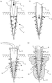
次に、図7を参照して、螺旋杭A’の埋設方法を説明する。 Next, a method for burying the spiral pile A ′ will be described with reference to FIG. 7.
図7(a)は、第一杭1を地中に埋設した状態を示している。第一杭1の埋設方法は、第1実施形態に係る螺旋杭Aの第一杭1の埋設方法と同様である。図7(a)では、第一杭1の開口部11からピンCの先端を挿入しているところを示している。ピンCは、図に示す矢印の方向に挿入される。
Fig.7 (a) has shown the state which embed | buried the
図7(b)は、ピンCを第一杭1の先端側まで挿入した状態を示している。各突出部材5は、後端をピンCの側面に押されて、第一杭1の各突出部材用孔18から外側に移動し、第一杭1の中心軸からほぼ垂直方向に向けて地中に突出した状態になっている。
FIG. 7B shows a state in which the pin C is inserted to the tip side of the
図7(c)は、ピンCを引き抜き、第一杭1の開口部11から空洞部12にセメントミルク4を注入している状態を示している。図7(c)では、空洞部12に注入されたセメントミルク4が、第一杭1の透孔14および突出部材5の透孔54から地中に吐出されている。
FIG. 7 (c) shows a state where the pin C is pulled out and
図7(d)は、適量のセメントミルク4を注入した後、注入を停止し、開口部11から支柱Bを挿入してボルト3で固定した状態を示している。図7(d)では、空洞部12に注入されて透孔14および透孔54から地中に吐出されたセメントミルク4が土壌を固結させ、第一杭1および突出部材5と一体となった固結塊4’を形成している。
FIG. 7 (d) shows a state in which, after injecting an appropriate amount of
第2実施形態においても、固結塊4’が第一杭1の側面側に広がった形に形成されるので、螺旋杭A’の支持力を従来の螺旋杭より大きくすることができる。したがって、第2実施形態においても、第1実施形態と同様の効果を奏することができる。
Also in the second embodiment, since the
なお、第2実施形態においても、第1実施形態の実施例(図4参照)のように、他の方法で支柱Bを螺旋杭A’に固定するようにしてもよい。 Also in the second embodiment, as in the example of the first embodiment (see FIG. 4), the column B may be fixed to the spiral pile A ′ by another method.
また、第2実施形態においては、突出部材5が第一杭1の中心軸に対してほぼ垂直方向に突出する場合について説明したが、これに限られない。例えば、図8に示すように、突出部材5が第一杭1の先端方向に向けて突出するようにしてもよい。この場合、突出部材5の中心軸方向の長さをより長くすることができる。
Moreover, in 2nd Embodiment, although the case where the
また、第2実施形態においては、第一杭1の開口部11から挿入されたピンCの側面で各突出部材5を押し出す場合について説明したが、これに限られない。例えば、突出部材用孔18の内側と突出部材5の側面とにねじ溝を設けて、突出部材5を回転させることで地中に突出させるようにしてもよい。
Moreover, in 2nd Embodiment, although the case where each
本発明に係る螺旋杭および埋設方法は、上述した実施形態に限定されるものではない。本発明に係る螺旋杭および埋設方法の各部の具体的な構成は、種々に設計変更自在である。 The spiral pile and the burying method according to the present invention are not limited to the above-described embodiment. The specific configuration of each part of the spiral pile and the embedding method according to the present invention can be varied in design in various ways.
A,A’ 螺旋杭
1 第一杭(中心杭)
10 杭本体
11 開口部(注入部)
12 空洞部
13 螺旋板
14 透孔
15 第二杭用孔(孔)
16 ボルト用孔
17 フランジ
18 突出部材用孔(孔)
2 第二杭(突出部材)
20 杭本体
21 開口部
22 空洞部
23 螺旋板
24 透孔
3 ボルト
4 セメントミルク
4’固結塊
5 突出部材
54 透孔
6 ナット
B 支柱
C ピン
A, A '
10
12
16
2 Second pile (protruding member)
DESCRIPTION OF
Claims (6)
前記杭本体の先端側の外周に螺旋状に設けられた螺旋板と、
前記杭本体の側面に設けられており、前記空洞部につながる透孔と、
土壌を固結させるための流動体を、前記空洞部に注入するための注入部と、
を備える中心杭と、
前記中心杭の側面から突出可能に配置される突出部材と、
を備えており、
前記突出部材にも、前記空洞部につながる透孔が設けられている、
ことを特徴とする螺旋杭。 A pile body having a substantially conical tip at the tip and a hollow portion inside,
A spiral plate spirally provided on the outer periphery of the front end side of the pile body;
Provided on the side surface of the pile body, and a through hole connected to the cavity,
An injection part for injecting a fluid for solidifying the soil into the cavity,
A central pile comprising:
A projecting member arranged to project from the side surface of the central pile;
With
The projecting member is also provided with a through hole that leads to the cavity,
Spiral pile characterized by that.
前記中心杭と同様の形状であり、
前記中心杭の後端に設けられた開口部から挿入されて、前記中心杭の側面に設けられた孔から、前記中心杭の先端側に向かって突出する、
請求項1に記載の螺旋杭。 The protruding member is
It is the same shape as the central pile,
Inserted from the opening provided at the rear end of the central pile, and projecting toward the tip side of the central pile from the hole provided in the side surface of the central pile,
The spiral pile according to claim 1.
請求項1または2に記載の螺旋杭。 A plurality of the protruding members are provided;
The spiral pile according to claim 1 or 2.
請求項1ないし3のいずれかに記載の螺旋杭。 The fluid is cement milk;
The spiral pile according to any one of claims 1 to 3.
前記空洞部につながる透孔が設けられている突出部材を、前記中心杭の側面に設けられた孔から突出させる第2の工程と、
土壌を固結させるための流動体を、前記空洞部に注入することで、前記各透孔から地中に吐出させる第3の工程と、
を備えていることを特徴とする埋設方法。 A pile main body having a substantially conical pointed tip and a hollow portion inside, a spiral plate spirally provided on the outer periphery on the tip side of the pile main body, and provided on a side surface of the pile main body, A first step of burying a central pile including a connecting through hole in the ground by rotating in a circumferential direction of the central axis;
A second step of causing a protruding member provided with a through hole connected to the hollow portion to protrude from a hole provided on a side surface of the central pile;
A third step of injecting a fluid for consolidating the soil into the cavity to discharge the fluid from the through holes into the ground;
An embedding method characterized by comprising:
前記第2の工程は、
前記中心杭の後端に設けられた開口部から前記突出部材を挿入する第4の工程と、
前記突出部材を中心軸の周方向に回転させることで、前記中心杭の側面に設けられた孔から前記中心杭の先端側に向かって、地中に埋設させる第5の工程と、
を備えている、
請求項5に記載の埋設方法。 The protruding member has the same shape as the central pile,
The second step includes
A fourth step of inserting the protruding member from an opening provided at the rear end of the central pile;
By rotating the projecting member in the circumferential direction of the central axis, from the hole provided on the side surface of the central pile toward the tip side of the central pile, a fifth step,
With
The embedding method according to claim 5.
Priority Applications (1)
| Application Number | Priority Date | Filing Date | Title |
|---|---|---|---|
| JP2013253967A JP2015113563A (en) | 2013-12-09 | 2013-12-09 | Screw pile and burying method thereof |
Applications Claiming Priority (1)
| Application Number | Priority Date | Filing Date | Title |
|---|---|---|---|
| JP2013253967A JP2015113563A (en) | 2013-12-09 | 2013-12-09 | Screw pile and burying method thereof |
Publications (1)
| Publication Number | Publication Date |
|---|---|
| JP2015113563A true JP2015113563A (en) | 2015-06-22 |
Family
ID=53527643
Family Applications (1)
| Application Number | Title | Priority Date | Filing Date |
|---|---|---|---|
| JP2013253967A Pending JP2015113563A (en) | 2013-12-09 | 2013-12-09 | Screw pile and burying method thereof |
Country Status (1)
| Country | Link |
|---|---|
| JP (1) | JP2015113563A (en) |
Cited By (3)
| Publication number | Priority date | Publication date | Assignee | Title |
|---|---|---|---|---|
| KR101843379B1 (en) * | 2017-06-20 | 2018-05-14 | 이승일 | Apparatus and method for reinforcing soft ground |
| KR20200017877A (en) * | 2018-08-09 | 2020-02-19 | 주식회사 아시아 | Fence construction method |
| CN113818430A (en) * | 2021-10-30 | 2021-12-21 | 中铁广州工程局集团有限公司 | Construction method of geological cement mixing pile with water-rich layer and sludge |
-
2013
- 2013-12-09 JP JP2013253967A patent/JP2015113563A/en active Pending
Cited By (5)
| Publication number | Priority date | Publication date | Assignee | Title |
|---|---|---|---|---|
| KR101843379B1 (en) * | 2017-06-20 | 2018-05-14 | 이승일 | Apparatus and method for reinforcing soft ground |
| KR20200017877A (en) * | 2018-08-09 | 2020-02-19 | 주식회사 아시아 | Fence construction method |
| KR102103583B1 (en) * | 2018-08-09 | 2020-04-23 | 주식회사 아시아 | Fence construction method |
| CN113818430A (en) * | 2021-10-30 | 2021-12-21 | 中铁广州工程局集团有限公司 | Construction method of geological cement mixing pile with water-rich layer and sludge |
| CN113818430B (en) * | 2021-10-30 | 2022-06-28 | 中铁广州工程局集团有限公司 | Construction method of geological cement mixing pile with water-rich layer and silt |
Similar Documents
| Publication | Publication Date | Title |
|---|---|---|
| CN104790424B (en) | The hardened system on generation power foundation of wind power ring basis and reinforcement means thereof | |
| KR101242476B1 (en) | Base construct method of building and base construct member of building | |
| EP2753765B1 (en) | Foundation structure of an offshore plant, in particular an offshore wind turbine, which foundation structure is to be installed at a low noise level, and installation method therefor | |
| JP2015113563A (en) | Screw pile and burying method thereof | |
| CN103603336B (en) | Grouting precast pile and grouting method | |
| JP2981213B1 (en) | Foundation piles and building structure | |
| CN205894069U (en) | Enlarged footing resistance to plucking stock | |
| CN201261950Y (en) | Open pore structure on steel reinforced concrete pond wall | |
| CN105735134A (en) | Temporary tensioning method for stub matching prefabricated box girders | |
| CN108589716A (en) | Reaming slip casting screw pile, pile foundation and pile construction method | |
| CN104695558A (en) | Pre-buried sleeve component for lacing wire of secondary structural wall | |
| CN203729605U (en) | Inter-column reinforcing structure for preventing historic building from collapsing continuously | |
| CN207092104U (en) | A kind of steel-pipe pile attachment structure | |
| KR101853185B1 (en) | Pile grouting device for enhanced friction of skin | |
| CN204385762U (en) | A kind of Rock Bolt Foundation structure | |
| JP2016061116A (en) | Foundation pile, method for installing foundation pile, and method for constructing solar panel | |
| JP2015148048A (en) | steel pipe pile foundation | |
| JP2011174306A (en) | Placement reinforcement material having function of drilling into soil and function of pull-out resistant force | |
| CN106013040A (en) | Auxiliary positioning bolt used for geocell | |
| KR20150004360U (en) | The spiral-shaped support structure | |
| CN111305201A (en) | Tensile type anchor | |
| JP2010138663A (en) | Manhole with floating-preventer | |
| CN104532873A (en) | Rock anchor rod foundation structure | |
| JP2007146468A (en) | Guy block mounting method and guy block | |
| CN204590257U (en) | A kind of embedded sleeve barrel assembly for secondary structure wall lacing wire |