JP2015105669A - Sleeve structure - Google Patents
Sleeve structure Download PDFInfo
- Publication number
- JP2015105669A JP2015105669A JP2013246471A JP2013246471A JP2015105669A JP 2015105669 A JP2015105669 A JP 2015105669A JP 2013246471 A JP2013246471 A JP 2013246471A JP 2013246471 A JP2013246471 A JP 2013246471A JP 2015105669 A JP2015105669 A JP 2015105669A
- Authority
- JP
- Japan
- Prior art keywords
- hole
- sleeve
- elastic member
- wall
- sleeve tube
- Prior art date
- Legal status (The legal status is an assumption and is not a legal conclusion. Google has not performed a legal analysis and makes no representation as to the accuracy of the status listed.)
- Pending
Links
Images


Abstract
Description
本発明は、建物の外壁に設備配管を貫通させるためのスリーブの構造に関する。 The present invention relates to a sleeve structure for penetrating equipment piping through an outer wall of a building.
下記特許文献1には、壁部に形成された貫通孔と、貫通孔に設けられた壁部貫通部材と、壁部貫通部材を貫通する配管とを具えたスリーブの構造が提案されている。この構造で用いられている壁部貫通部材は、配管を保持する本体と、本体の外部に形成される止水部とを有している。 Patent Document 1 below proposes a structure of a sleeve including a through hole formed in a wall portion, a wall portion penetrating member provided in the through hole, and a pipe penetrating the wall portion penetrating member. The wall portion penetrating member used in this structure has a main body that holds the pipe and a water stop portion that is formed outside the main body.
止水部は、本体の外周面と貫通孔の内周面との間において、壁部の外側に配置される弾性部材と、弾性部材に対して壁部の内側に配置される水膨張性不織布とを含んで構成されている。弾性部材は、本体と貫通孔との間で弾性変形することにより、貫通孔の止水性を高めている。また、水膨張性不織布は、雨水の浸入によって膨張し、貫通孔の止水性を高めている。 The water-stop portion is an elastic member disposed outside the wall portion between the outer peripheral surface of the main body and the inner peripheral surface of the through hole, and a water-swellable nonwoven fabric disposed inside the wall portion with respect to the elastic member It is comprised including. The elastic member is elastically deformed between the main body and the through hole, thereby increasing the water stoppage of the through hole. Moreover, the water-expandable nonwoven fabric expands due to the intrusion of rainwater and increases the water-stopping property of the through hole.
しかしながら、特許文献1の構造において、貫通孔の内面に凹凸があった場合、弾性部材では、雨水の貫通孔への浸入を防ぐことが難しい。そこから浸入した水分で、外壁の劣化が促進されるという問題があった。 However, in the structure of Patent Document 1, when the inner surface of the through hole is uneven, it is difficult for the elastic member to prevent rainwater from entering the through hole. There was a problem that the deterioration of the outer wall was promoted by the moisture that entered from there.
本発明は、以上のような実状に鑑み案出されたもので、スリーブ管と貫通孔との間で外壁の外面から凹む凹部に、シーリング材を充填することを基本として、貫通孔の止水性を高めうるスリーブの構造を提供することを主たる目的としている。 The present invention has been devised in view of the actual situation as described above, and is based on the fact that a concave portion recessed from the outer surface of the outer wall between the sleeve tube and the through-hole is filled with a sealing material, and the water-stopping property of the through-hole. The main object is to provide a sleeve structure that can improve the height of the sleeve.
本発明は、建物の外壁に設備配管を貫通させるためのスリーブの構造であって、前記外壁の屋外側の外面と、前記外壁の屋内側の内面との間を連通する貫通孔、前記貫通孔に配置され、かつ、前記設備配管を案内するスリーブ管、前記外面よりも前記内面側に控えた位置で、前記スリーブ管と前記貫通孔との間に圧縮状態で配置されることにより、前記スリーブ管と前記貫通孔との間で前記外面から凹む凹部を形成する弾性部材、及び前記凹部に充填されるシーリング材を含むことを特徴とする。 The present invention relates to a sleeve structure for allowing equipment piping to pass through an outer wall of a building, the through-hole communicating between the outer surface of the outer wall on the outdoor side and the inner surface of the outer wall on the indoor side, the through-hole And a sleeve tube that guides the equipment piping, and is disposed in a compressed state between the sleeve tube and the through hole at a position that is further on the inner surface side than the outer surface. It includes an elastic member that forms a recess recessed from the outer surface between the tube and the through hole, and a sealing material that fills the recess.
本発明に係る前記スリーブの構造において、前記弾性部材は、水密材からなるのが望ましい。 In the sleeve structure according to the present invention, the elastic member is preferably made of a watertight material.
本発明に係る前記スリーブの構造において、前記シーリング材は、前記スリーブ管の軸方向において、前記弾性部材と当接しているのが望ましい。 In the sleeve structure according to the present invention, it is desirable that the sealing material is in contact with the elastic member in the axial direction of the sleeve tube.
本発明のスリーブの構造は、外壁の屋外側の外面と、外壁の屋内側の内面との間を連通する貫通孔、及び、貫通孔に配置され、かつ、設備配管を案内するスリーブ管を含んでいる。さらに、スリーブの構造は、外面よりも内面側に控えた位置で、スリーブ管と貫通孔との間に圧縮状態で配置されることにより、スリーブ管と貫通孔との間で外面から凹む凹部を形成する弾性部材、及び、凹部に充填されるシーリング材を含んでいる。 The structure of the sleeve of the present invention includes a through hole that communicates between an outer surface of the outer wall on the outdoor side and an inner surface of the outer wall on the indoor side, and a sleeve pipe that is disposed in the through hole and guides the equipment piping. It is out. Furthermore, the structure of the sleeve is arranged in a compressed state between the sleeve tube and the through hole at a position reserved on the inner surface side with respect to the outer surface, thereby forming a recess recessed from the outer surface between the sleeve tube and the through hole. An elastic member to be formed and a sealing material filled in the recess are included.
このようなスリーブの構造では、スリーブ管と貫通孔との間に、弾性部材が圧縮状態で配置されるため、スリーブ管を、貫通孔に安定して保持することができる。また、弾性部材は、スリーブ管と貫通孔との間の隙間において気密性を高めることができ、外壁の断熱性の低下を防ぐことができる。さらに、弾性部材は、シーリング材のバックアップ材として用いることができ、施工性を向上しうる。また、弾性部材が、シーリング材と接着しない材料から形成される場合には、ボンドブレーカーが不要となるため、施工性をさらに向上させることができる。 In such a sleeve structure, since the elastic member is disposed in a compressed state between the sleeve tube and the through hole, the sleeve tube can be stably held in the through hole. Further, the elastic member can improve the airtightness in the gap between the sleeve tube and the through hole, and can prevent the heat insulation of the outer wall from being lowered. Furthermore, the elastic member can be used as a backup material for the sealing material, and can improve the workability. Moreover, when an elastic member is formed from the material which does not adhere | attach with a sealing material, since a bond breaker becomes unnecessary, workability | operativity can be improved further.
シーリング材は、貫通孔の内面に凹凸が形成されていても、外壁の外面から凹む凹部において、貫通孔の内周面とスリーブ管の外周面との間に隙間なく配置することができる。このため、シーリング材は、貫通孔に雨水が浸入するのを確実に防ぐことができる。従って、本発明のスリーブの構造は、貫通孔の止水性を高めることができ、外壁の劣化を抑制することができる。 Even if the inner surface of the through hole is uneven, the sealing material can be disposed without a gap between the inner peripheral surface of the through hole and the outer peripheral surface of the sleeve tube in the concave portion recessed from the outer surface of the outer wall. For this reason, the sealing material can reliably prevent rainwater from entering the through hole. Therefore, the structure of the sleeve of the present invention can increase the water-stopping property of the through hole and can suppress the deterioration of the outer wall.
以下、本発明の実施の一形態が図面に基づき説明される。
本実施形態のスリーブの構造は、一般的な住宅やビル等の建物の外壁に、例えば、エアコン等の設備配管を貫通させるためのものである。図1は、本実施形態のスリーブの構造を示す断面図である。図2は、図1のスリーブの構造の分解断面図である。図3は、図1の部分拡大断面図である。
Hereinafter, an embodiment of the present invention will be described with reference to the drawings.
The structure of the sleeve of this embodiment is for penetrating equipment piping such as an air conditioner through the outer wall of a building such as a general house or building. FIG. 1 is a cross-sectional view showing the structure of the sleeve of this embodiment. FIG. 2 is an exploded cross-sectional view of the sleeve structure of FIG. FIG. 3 is a partially enlarged sectional view of FIG.
図1に示されるように、本実施形態の外壁2は、パネル状に形成されている。外壁2は、例えば、矩形に枠組みされた枠体3と、該枠体3の屋外側Soに配された外装材4と、枠体3の屋内側Siに配された内装材5とを含んで構成されている。
As shown in FIG. 1, the
枠体3は、従来の枠体と同様に、外壁2の上端側を水平にのびる上の枠材3Aと、下端側を水平にのびる下の枠材3Bと、これらの間を左右両端で継ぐ左右の枠材(図示省略)とを含んでいる。また、枠体3には、上記各枠材間を水平及び垂直方向にのびる桟材(図示省略)が設けられている。
Similar to the conventional frame body, the
外装材4には、例えば、ALC等の発泡コンクリートパネルや、セメントと木質補強材料との原料混合物のスラリーを養生硬化させた窯業系外装パネルなどが用いられる。内装材5には、例えば、強度の高い構造用合板や、調湿性を有する石膏ボードなどが用いられる。
As the exterior material 4, for example, a foamed concrete panel such as ALC, or a ceramic-based exterior panel obtained by curing and curing a slurry of a raw material mixture of cement and a wood reinforcing material is used. For the
外壁2の内部には、断熱材6が配されている。断熱材6としては、例えば、ロックウールや、グラスウール等の繊維材等の他、耐水性及び軽量性に優れるポリスチレンフォーム等の樹脂材を採用することができる。
Inside the
図1〜図3に示されるように、本実施形態のスリーブの構造は、貫通孔11、スリーブ管12、弾性部材13、及び、シーリング材14を含んで構成されている。
As shown in FIGS. 1 to 3, the structure of the sleeve according to the present embodiment includes a through
貫通孔11は、外壁2の屋外側Soの外面(以下、単に「外面」ということがある。)2oと、外壁2の屋内側Siの内面(以下、単に「内面」ということがある。)2iとの間を連通し、略円柱状に形成されている。本実施形態の貫通孔11は、外装材4の孔部11a、内装材5の孔部11b、及び、断熱材6の孔部11cを含んで構成されている。これらの孔部11a、11b及び11cが水平方向で連通することにより、貫通孔11が形成されている。
The through-
外装材4の孔部11aの内径D1a、内装材5の孔部11bの内径D1b、及び、断熱材6の孔部11cの内径(図示省略)は、例えば、スリーブ管12の外径D2や、弾性部材13の外径D3(図4に示す)に基づいて、適宜設定することができる。本実施形態では、外装材4の孔部11aの内径D1aが、内装材5の孔部11bの内径D1bよりも大に設定される。なお、外装材4の孔部11aの内径D1aは、例えば、80mm〜120mm程度に設定されている。また、内装材5の孔部11bの内径D1bは、例えば、70mm〜90mm程度に設定されている。
The inner diameter D1a of the
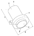
図4は、本実施形態のスリーブ管12及び弾性部材13の斜視図である。図2及び図4に示されるように、スリーブ管12は、孔部16を有する円筒状に形成され、外壁2の貫通孔11に配置されている。スリーブ管12の孔部16には、設備配管17(図1に示す)が配置される。また、スリーブ管12の軸方向の長さL2は、外壁2の外面2oと内面2iとの間の距離L1と、略同一に設定されている。これにより、スリーブ管12は、貫通孔11において、孔部16に配置される設備配管17を、屋内側Siから屋外側Soに案内することができる。
FIG. 4 is a perspective view of the
図2に示されるように、本実施形態では、スリーブ管12の屋外側So側の一端12oが、外壁2の外面2oよりも内面2i側に控えた位置に配置されている。また、スリーブ管12の屋内側Si側の他端12iは、外壁2の内面2iよりも外面2o側に控えた位置に配置されている。これにより、スリーブ管12は、一端12o及び他端12iの双方に配置されるスリーブキャップ21、21との干渉を防ぐことができる。
As shown in FIG. 2, in the present embodiment, the one end 12 o on the outdoor side So side of the
スリーブ管12の外径D2は、貫通孔11の各内径D1a、D1b及びD1cよりも小であれば、設備配管17の大きさに応じて適宜設定することができる。本実施形態のスリーブ管12の外径D2は、例えば、65mm〜85mm程度に設定されている。また、スリーブ管12は、例えば、塩化ビニール等の合成樹脂や、ステンレス等の金属から形成することができる。
As long as the outer diameter D2 of the
スリーブキャップ21、21は、従来のスリーブキャップと同様に、スリーブ管12に固着される基部22と、基部22に取り外し可能に固着される蓋部23とを含んでいる。
The sleeve caps 21 and 21 include a
基部22は、スリーブ管12の内面に固着される筒部22aと、筒部22aの端部でフランジ状にのびる鍔部22bとを含んで構成されている。筒部22aの外面とスリーブ管12の内面との間には、シーリング材(図示省略)が充填されている。このようなスリーブキャップ21、21は、スリーブ管12に設備配管17が配置されない未使用状態において、スリーブ管12の一端12o及び他端12iに設けられる開口部を閉じることができる。
The
図2及び図4に示されるように、弾性部材13は、スリーブ管12の周方向に連続する略円筒状に形成されている。本実施形態の弾性部材13は、スリーブ管12の外周面に、予め固着されている。弾性部材13の軸方向の長さL3は、スリーブ管12の軸方向の長さL2よりも小に設定されている。本実施形態の長さL3は、例えば、スリーブ管12の長さL2の15%〜40%程度に設定されている。
As shown in FIGS. 2 and 4, the
弾性部材13の外径D3は、貫通孔11の内径(外装材4の孔部11aの内径D1a、内装材5の孔部11bの内径D1b、及び、断熱材6の孔部11cの内径(図示省略))よりも大に設定されている。
The outer diameter D3 of the
これにより、弾性部材13は、スリーブ管12と貫通孔11との間で弾性変形することができ、その復元力を利用して、スリーブ管12を、貫通孔11に安定して保持することができる。また、弾性部材13は、スリーブ管12と貫通孔11との間の隙間において、気密性を高めることができるため、外壁2の断熱性の低下を防ぐことができる。本実施形態の弾性部材13は、断熱材6よりも硬質な外装材4と、スリーブ管12との間において、大きく圧縮変形している。
Thereby, the
弾性部材13の外径D3は、貫通孔11の内径(外装材4の孔部11aの内径D1a)よりも大であれば、適宜設定することができる。本実施形態の弾性部材13の外径D3は、例えば、孔部11aの内径D1aの105%〜120%程度に設定されるのが望ましい。
The outer diameter D3 of the
図4に示されるように、弾性部材13は、一端12oよりも他端12i側に控えた位置で、スリーブ管12に固着されている。このため、図3に示されるように、弾性部材13は、スリーブ管12が貫通孔11に配置された状態において、外壁2の外面2oよりも内面2i(図2に示す)側に控えた位置で固着される。これにより、弾性部材13は、スリーブ管12と貫通孔11との間に、外面2oから凹む凹部26を形成することができる。本実施形態の凹部26は、外壁2の外面2oにおいて、スリーブ管12の周方向に連続するリング状に形成されている。
As shown in FIG. 4, the
弾性部材13としては、スリーブ管12と貫通孔11との間で圧縮変形するものであれば、適宜採用することができる。弾性部材13としては、水密材によって形成されるのが望ましい。このような弾性部材13は、外装材4の孔部11a及び断熱材6に、雨水が浸入するのを防ぐことができ、貫通孔11の止水性を高めることができる。なお、弾性部材13を形成する水密材としては、例えば、ウレタン系発泡水密材、EPDM発泡水密材、又は、水膨張性水密材等を採用することができる。なお、本実施形態では、日本発条(株)製のスーパーシートH3が用いられている。
As the
図3に示されるように、弾性部材13は、スリーブ管12の軸方向において、弾性部材13の少なくとも一部が、外装材4の孔部11aに重複する位置に固着されるのが望ましい。これにより、弾性部材13は、断熱材6よりも硬質な外装材4と、スリーブ管12との間で効果的に圧縮変形することができるため、スリーブ管12を安定して保持することができる。なお、弾性部材13と外装材4の孔部11aとの重複長さL5は、弾性部材13の軸方向の長さL3の10%〜100%程度が望ましい。
As shown in FIG. 3, it is desirable that the
本実施形態の弾性部材13としては、スリーブ管12に固着されるのに先立ち、円筒状に予め加工されているものが例示されたが、これに限定されるわけではない。図5は、本発明の他の実施形態のスリーブ管12及び弾性部材13を示す斜視図である。
As the
この実施形態の弾性部材13は、シート状の弾性部材13sをスリーブ管12に巻き重ねることにより、円筒状に形成されている。このような弾性部材13は、貫通孔11の内径(外装材4の孔部11aの内径D1a)等に応じて、弾性部材13の外径D3(図4に示す)を柔軟に設定することができるため、施工性を向上することができる。
The
図3に示されるように、シーリング材14は、スリーブ管12と貫通孔11との間で、外面2oから凹む凹部26に充填されている。
As shown in FIG. 3, the sealing
硬化前のシーリング材14は、例えば、貫通孔11(外装材4の孔部11a)の内面に、弾性部材13が追従できないほどの大きな凹凸が形成されていても、該凹凸の間に柔軟に入り込むことができる。このため、シーリング材14は、貫通孔11の内周面とスリーブ管12の外周面との間に、隙間なく配置することができる。これにより、シーリング材14は、外壁2の外面2o側において、貫通孔11(スリーブ管12と貫通孔11との間の隙間)に、雨水が浸入するのを確実に防ぐことができる。従って、本発明のスリーブの構造は、貫通孔11の止水性を確実に高めることができ、外壁2の劣化を抑制することができる。
For example, the sealing
スリーブ管12の軸方向において、シーリング材14の深さ(凹部26の長さ)L4については、適宜設定することができる。スリーブ管12と貫通孔11との間の隙間に、雨水が浸入するのを確実に防ぐために、シーリング材14の深さL4は、外装材4の厚さW1の50%〜80%に設定されるのが望ましい。また、シーリング材14としては、例えば、建築用シーリング材、アスファルトシーリング、又は、ポリマーセメントシーリングを採用することができる。
In the axial direction of the
シーリング材14は、スリーブ管12の軸方向において、弾性部材13と当接しているのが望ましい。これにより、シーリング材14は、弾性部材13とともに、スリーブ管12と貫通孔11との間の隙間に、雨水が浸入するのを防ぐことができる。また、弾性部材13は、シーリング材14が屋内側Siに必要以上に充填されるのを防ぐバックアップ材として用いることができ、施工性を向上しうる。なお、弾性部材13には、シーリング材14と接着しない材料から形成されてもよい。これにより、弾性部材13とシーリング材14との接着を防ぐボンドブレーカー(図示省略)が不要となるため、施工性をさらに向上させることができる。
The sealing
次に、スリーブの構造の施工方法の一例について説明する。
本実施形態の施工方法では、先ず、建物の外壁2に、外面2oと内面2iとの間を連通する貫通孔11が設けられる(工程S1)。図6は、工程S1を説明する断面図である。工程S1では、先ず、外装材4及び内装材5の双方に、正面視略円形状の孔部11a、11bが形成される。次に、断熱材6に、外装材4の孔部11aと、内装材5の孔部11bとの間を連通する円筒状の孔部11cが形成される。これにより、工程S1では、外面2oと内面2iとの間を連通する貫通孔11を形成することができる。なお、貫通孔11の寸法等については、上記のとおりである。
Next, an example of a construction method of the sleeve structure will be described.
In the construction method of this embodiment, first, the through-
次に、弾性部材13が固着されたスリーブ管12(図4に示す)が、貫通孔11に配置される(工程S2)。図7は、工程S2を説明する断面図である。工程S2では、先ず、スリーブ管12が、その他端12iから外装材4の孔部11aに挿入される。上述したように、弾性部材13の外径D3は、外装材4の孔部11aの内径D1aよりも大に設定されている。このため、弾性部材13は、半径方向内側に圧縮変形されながら、外装材4の孔部11aにねじ込まれる。これにより、工程S2では、スリーブ管12と貫通孔11(外装材4の孔部11a)との間に、弾性部材13を圧縮状態で配置することができる。
Next, the sleeve tube 12 (shown in FIG. 4) to which the
弾性部材13は、スリーブ管12が貫通孔11に配置された状態において、外壁2の外面2oよりも内面2i側に控えた位置に固着されている。このため、工程S2では、スリーブ管12と貫通孔11との間に、外面2oから凹む凹部26を形成することができる。
The
次に、シーリング材14が凹部26に充填される(工程S3)。図8は、工程S3を説明する断面図である。工程S3では、例えば、コーキングガン等を用いて、凹部26にシーリング材14が充填される。本実施形態では、シーリング材14が、外面2oから弾性部材13まで隙間なく充填されている。これにより、弾性部材13は、シーリング材14が、屋内側Siに必要以上に充填されるのを防ぐバックアップ材として用いることができるため、施工性を向上しうる。そして、シーリング材14の硬化後、又は、シーリング材14の養生中に、次の工程S4が実施される。
Next, the sealing
次に、スリーブ管12の一端12o及び他端12iに、スリーブキャップ21、21(図9に示す)が取り付けられる(工程S4)。図9は、工程S4を説明する断面図である。工程S4では、先ず、各スリーブキャップ21、21の筒部22aの外周面に、シーリング材(図示省略)が塗布される。本実施形態では、筒部22aの周方向に沿って、シーリング材が棒状に塗布される。次に、各スリーブキャップ21、21の筒部22aが、スリーブ管12に挿入される。このとき、各スリーブキャップ21、21の鍔部22bが、外壁2の外面2o又は内面2iに当接される。そして、シーリング材の硬化により、スリーブキャップ21、21が、スリーブ管12に固着される。
Next, sleeve caps 21 and 21 (shown in FIG. 9) are attached to the one end 12o and the
なお、シーリング材が硬化するまでの間、例えば、マスキングテープを用いて、スリーブキャップ21、21を、外壁2に仮固定しておくのが望ましい。これにより、スリーブキャップ21、21が、スリーブ管12から脱落するのを防ぐことができる。
It is desirable that the sleeve caps 21 and 21 are temporarily fixed to the
このように、上記工程S1〜工程S4が順次実施されることにより、本実施形態のスリーブの構造を形成することができる。なお、図1に示されるように、スリーブ管12に設備配管17を案内させる場合、スリーブキャップ21、21の蓋部23、23が取り外される。これにより、スリーブの構造は、スリーブキャップ21、21の基部22、22及びスリーブ管12を介して、設備配管17を外壁2に貫通させることができる。
Thus, the structure of the sleeve of the present embodiment can be formed by sequentially performing the above-described steps S1 to S4. As shown in FIG. 1, when the
以上、本発明の特に好ましい実施形態について詳述したが、本発明は図示の実施形態に限定されることなく、種々の態様に変形して実施しうる。 As mentioned above, although especially preferable embodiment of this invention was explained in full detail, this invention is not limited to embodiment of illustration, It can deform | transform and implement in a various aspect.
2 外壁
11 貫通孔
12 スリーブ管
13 弾性部材
14 シーリング材
17 設備配管
26 凹部
2
Claims (3)
前記外壁の屋外側の外面と、前記外壁の屋内側の内面との間を連通する貫通孔、
前記貫通孔に配置され、かつ、前記設備配管を案内するスリーブ管、
前記外面よりも前記内面側に控えた位置で、前記スリーブ管と前記貫通孔との間に圧縮状態で配置されることにより、前記スリーブ管と前記貫通孔との間で前記外面から凹む凹部を形成する弾性部材、及び
前記凹部に充填されるシーリング材を含むことを特徴とするスリーブの構造。 A structure of a sleeve for penetrating equipment piping through the outer wall of a building,
A through-hole communicating between the outer surface on the outdoor side of the outer wall and the inner surface on the indoor side of the outer wall;
A sleeve pipe disposed in the through hole and guiding the equipment pipe;
A recess recessed from the outer surface between the sleeve tube and the through-hole is disposed in a compressed state between the sleeve tube and the through-hole at a position reserved on the inner surface side of the outer surface. A sleeve structure comprising: an elastic member to be formed; and a sealing material filled in the recess.
Priority Applications (1)
| Application Number | Priority Date | Filing Date | Title |
|---|---|---|---|
| JP2013246471A JP2015105669A (en) | 2013-11-28 | 2013-11-28 | Sleeve structure |
Applications Claiming Priority (1)
| Application Number | Priority Date | Filing Date | Title |
|---|---|---|---|
| JP2013246471A JP2015105669A (en) | 2013-11-28 | 2013-11-28 | Sleeve structure |
Publications (1)
| Publication Number | Publication Date |
|---|---|
| JP2015105669A true JP2015105669A (en) | 2015-06-08 |
Family
ID=53435915
Family Applications (1)
| Application Number | Title | Priority Date | Filing Date |
|---|---|---|---|
| JP2013246471A Pending JP2015105669A (en) | 2013-11-28 | 2013-11-28 | Sleeve structure |
Country Status (1)
| Country | Link |
|---|---|
| JP (1) | JP2015105669A (en) |
Cited By (1)
| Publication number | Priority date | Publication date | Assignee | Title |
|---|---|---|---|---|
| CN111963779A (en) * | 2020-08-19 | 2020-11-20 | 北京中房国建地下防水工程顾问有限公司 | Floor sleeve joint waterproof construction |
Citations (4)
| Publication number | Priority date | Publication date | Assignee | Title |
|---|---|---|---|---|
| JPS51150115A (en) * | 1975-06-17 | 1976-12-23 | Hitachi Plant Eng & Constr Co Ltd | Sealing between piping and concrete pit |
| JPS59110991A (en) * | 1982-12-14 | 1984-06-27 | 日本電信電話株式会社 | Waterproof airtight piping penetrating method with displacement absorbing mechanism |
| JP2001235196A (en) * | 2000-02-23 | 2001-08-31 | National House Industrial Co Ltd | Outdoor grille |
| JP2005214247A (en) * | 2004-01-28 | 2005-08-11 | Sekisui House Ltd | Waterproof structure in penetrated part of vertical gutter, etc. |
-
2013
- 2013-11-28 JP JP2013246471A patent/JP2015105669A/en active Pending
Patent Citations (4)
| Publication number | Priority date | Publication date | Assignee | Title |
|---|---|---|---|---|
| JPS51150115A (en) * | 1975-06-17 | 1976-12-23 | Hitachi Plant Eng & Constr Co Ltd | Sealing between piping and concrete pit |
| JPS59110991A (en) * | 1982-12-14 | 1984-06-27 | 日本電信電話株式会社 | Waterproof airtight piping penetrating method with displacement absorbing mechanism |
| JP2001235196A (en) * | 2000-02-23 | 2001-08-31 | National House Industrial Co Ltd | Outdoor grille |
| JP2005214247A (en) * | 2004-01-28 | 2005-08-11 | Sekisui House Ltd | Waterproof structure in penetrated part of vertical gutter, etc. |
Cited By (1)
| Publication number | Priority date | Publication date | Assignee | Title |
|---|---|---|---|---|
| CN111963779A (en) * | 2020-08-19 | 2020-11-20 | 北京中房国建地下防水工程顾问有限公司 | Floor sleeve joint waterproof construction |
Similar Documents
| Publication | Publication Date | Title |
|---|---|---|
| CA2852270C (en) | Continuous wall assemblies and methods | |
| US10487964B2 (en) | Line leadthrough with integrated smoke stopper | |
| CN207936350U (en) | A kind of residence outer wall air-conditioning pierces muscle plastic bushing | |
| JP2015105669A (en) | Sleeve structure | |
| US9523232B2 (en) | Filling material, window and door set, and filling method | |
| KR101059345B1 (en) | Double telescopic tube for double wall | |
| US10044179B2 (en) | Method of installing elongate bodies in a building | |
| KR20170004066U (en) | Dryvit area building law | |
| JP6916241B2 (en) | Pipe fitting structure | |
| DE102013210798B3 (en) | Device for a passage through a wall of a prefabricated house and method for attaching such a passage to a component of a prefabricated house | |
| JP2004308772A (en) | Sleeve for pipe | |
| US20130000073A1 (en) | Pipe sleeve | |
| JP5006906B2 (en) | Lath net and lath net with tarpaulin | |
| KR101602773B1 (en) | Fire prevention sleeve for dry type air duct system, constructing structure and method using this | |
| JP2013147840A (en) | Fireproof treatment structure of penetration part of piping/wiring | |
| JP2011032862A (en) | Method of constructing exterior wall using horizontal slit member and exterior wall structure | |
| KR20170042030A (en) | A Panel For Inner Or Outer Wall Of Building | |
| JP6393605B2 (en) | Joint structure | |
| CN210266214U (en) | Subway tuber pipe fire prevention plugging device | |
| KR102269623B1 (en) | Gang foam with noise protection and insulation | |
| JP2020037795A (en) | Piping structure, edge part handling member of collective joint, and method of handling edge part of collective joint | |
| CN106642413A (en) | Air conditioner mounting structure for outer wall of building | |
| FI127252B (en) | Method of forming an insulated ventilation duct and insulated ventilation duct | |
| JP4833688B2 (en) | Piping support and building equipped with the pipe support | |
| JP2016211144A (en) | Vertical joint structure, and installation method of vertical joint structure |
Legal Events
| Date | Code | Title | Description |
|---|---|---|---|
| A621 | Written request for application examination |
Free format text: JAPANESE INTERMEDIATE CODE: A621 Effective date: 20160824 |
|
| A977 | Report on retrieval |
Free format text: JAPANESE INTERMEDIATE CODE: A971007 Effective date: 20170412 |
|
| A131 | Notification of reasons for refusal |
Free format text: JAPANESE INTERMEDIATE CODE: A131 Effective date: 20170418 |
|
| A02 | Decision of refusal |
Free format text: JAPANESE INTERMEDIATE CODE: A02 Effective date: 20171107 |