本発明は、例えば空気調和機の室内機に関する。
The present invention relates to an indoor unit of an air conditioner, for example.
従来の室内機には、ケーシングと、ケーシングの前方に配置される前面パネルとを備えたものがある。この室内機は、ケーシングの天面部に配置された吸込口と、ケーシングの内部に配置されたクロスフローファンとを有している。したがって、天面部の吸込口から吸い込まれた空気がクロスフローファンに供給され、その後、クロスフローファンからの空気が吹出口から吹き出される。
Some conventional indoor units include a casing and a front panel disposed in front of the casing. This indoor unit has a suction port disposed in the top surface portion of the casing and a cross flow fan disposed in the casing. Therefore, the air sucked from the suction port of the top surface portion is supplied to the cross flow fan, and then the air from the cross flow fan is blown out from the blower outlet.
特開2011−149620JP2011-149620A
室内機の内部に配置されたクロスフローファンは、その長手方向中央部において最も風量が大きくなる特性を有しているが、従来の室内機では、吸込口の幅が長手方向に一定の幅であることから、吸込口から吸い込まれた空気がクロスフローファンの長手方向中央部に対して十分に供給されないという問題がある。
The cross flow fan arranged inside the indoor unit has the characteristic that the air volume is the largest at the center in the longitudinal direction, but in the conventional indoor unit, the width of the suction port is constant in the longitudinal direction. Therefore, there is a problem that the air sucked from the suction port is not sufficiently supplied to the central portion in the longitudinal direction of the cross flow fan.
そこで、本発明の目的は、クロスフローファンの長手方向中央部に対して十分に空気を供給できる室内機を提供することである。
Then, the objective of this invention is providing the indoor unit which can fully supply air with respect to the longitudinal direction center part of a crossflow fan.
第1の発明にかかる室内機は、吸込口が配置された天面部を有し、クロスフローファンを収容する室内機であって、前記天面部は、その前端の中央部が前方に膨出するように湾曲しており、前記吸込口は、長手方向について前記天面部の前端の中央部に対応した吸込中央部の幅が長手方向両端の幅より広く構成されることを特徴とする。
An indoor unit according to a first aspect of the present invention is an indoor unit that has a top surface part in which a suction port is arranged and accommodates a cross flow fan, and the top surface part of the top surface part bulges forward. In the longitudinal direction, the suction port is configured such that the width of the suction central portion corresponding to the central portion of the front end of the top surface portion is wider than the width of both ends in the longitudinal direction.
この室内機では、吸込口において天面部の前端の中央部に対応した吸込中央部の幅が長手方向両端の幅より広く構成されているので、クロスフローファンの中央部近傍における風量を増加させることができる。
In this indoor unit, since the width of the suction center portion corresponding to the center portion of the front end of the top surface portion is wider than the width of both ends in the longitudinal direction at the suction port, the air volume in the vicinity of the center portion of the cross flow fan is increased. Can do.
第2の発明にかかる室内機では、第1の発明にかかる室内機において、前記吸込口の幅は、前記吸込中央部において最大であることを特徴とする。
In the indoor unit according to the second aspect of the invention, in the indoor unit according to the first aspect of the invention, the width of the suction port is maximum at the suction center.
この室内機では、吸込口の吸込中央部の幅が最大になるように構成されているので、クロスフローファンにおいて最も風量を大きくしやすい中央部近傍の風量を増加させることができる。
In this indoor unit, since the width of the suction center portion of the suction port is maximized, it is possible to increase the air volume in the vicinity of the center portion where the air volume is most likely to be increased most in the crossflow fan.
第3の発明にかかる室内機では、第2の発明にかかる室内機において、前記吸込口は、その前端が前方に膨出するように湾曲しており、前記吸込口の幅は、前記吸込中央部から長手方向両端に近づくにつれて狭くなることを特徴とする。
In the indoor unit according to a third aspect of the invention, in the indoor unit according to the second aspect of the invention, the suction port is curved so that the front end bulges forward, and the width of the suction port is set at the suction center. It becomes narrow as it approaches a longitudinal direction both ends from a part.
この室内機では、吸込口の幅が吸込中央部から長手方向両端に近づくにつれて狭くなるように前方に膨出するように湾曲しているので、吹出口の長手方向において急激に気流が変化するのを抑制できる。
In this indoor unit, the airflow changes suddenly in the longitudinal direction of the air outlet because it is curved so as to swell forward so that the width of the air inlet becomes narrower from the suction center to both ends in the longitudinal direction. Can be suppressed.
第4の発明にかかる室内機では、第1−第3のいずれかの発明にかかる室内機において、下端に近づくにつれて背面に近づくように傾斜する前面を有することを特徴とする。
An indoor unit according to a fourth aspect of the invention is characterized in that the indoor unit according to any of the first to third aspects has a front surface that inclines so as to approach the back as it approaches the lower end.
この室内機では、室内機の前面が下端に近づくにつれて背面に近づくように傾斜するので、室内機の下面部の奥行長さが室内機の天面部の奥行長さより短いので、ユーザが室内機を下方から見たときに薄型のイメージを与えることができる。
In this indoor unit, since the front surface of the indoor unit is inclined so as to approach the back as it approaches the lower end, the depth length of the lower surface portion of the indoor unit is shorter than the depth length of the top surface portion of the indoor unit. A thin image can be given when viewed from below.
第5の発明にかかる室内機では、第1−第4のいずれかの発明にかかる室内機において、前記天面部を有するケーシングと、前記ケーシングの前方に配置される前面パネルとを備え、前記前面パネルは、その中央部が前方に膨出するように湾曲することを特徴とする。
An indoor unit according to a fifth invention is the indoor unit according to any one of the first to fourth inventions, comprising a casing having the top surface portion and a front panel arranged in front of the casing, The panel is characterized in that it is curved so that its central portion bulges forward.
この室内機では、前面パネルの中央部が前方に膨出するように湾曲するので、ユーザが室内機を左右方向から見たときに薄型のイメージを与えることができる。
In this indoor unit, since the center part of the front panel is curved so as to bulge forward, it is possible to give a thin image when the user views the indoor unit from the left-right direction.
第6の発明にかかる室内機では、第5の発明にかかる室内機において、前記前面パネルは、前記ケーシングの前面から離れるように移動可能であることを特徴とする。
In the indoor unit according to a sixth aspect of the invention, in the indoor unit according to the fifth aspect of the invention, the front panel is movable away from the front surface of the casing.
この室内機では、前面パネルをケーシングの前面から離れるように移動させることにより、前面パネルとケーシングとの間の隙間から空気を吸い込んで吸込量を増加させることができる。
In this indoor unit, by moving the front panel away from the front surface of the casing, air can be sucked from the gap between the front panel and the casing to increase the amount of suction.
以上の説明に述べたように、本発明によれば、以下の効果が得られる。
As described above, according to the present invention, the following effects can be obtained.
第1の発明では、吸込口において天面部の前端の中央部に対応した吸込中央部の幅が長手方向両端の幅より広く構成されているので、クロスフローファンの中央部近傍における風量を増加させることができる。
第2の発明では、吸込口の吸込中央部の幅が最大になるように構成されているので、クロスフローファンにおいて最も風量を大きくしやすい中央部近傍の風量を増加させることができる。
In 1st invention, since the width | variety of the suction center part corresponding to the center part of the front-end | tip of a top | upper surface part in a suction port is comprised more widely than the width | variety of both ends of a longitudinal direction, the air volume in the center part vicinity of a crossflow fan is increased. be able to.
In the second invention, since the width of the suction central portion of the suction port is maximized, the airflow in the vicinity of the central portion where the airflow is most easily increased in the crossflow fan can be increased.
第3の発明では、吸込口の幅が吸込中央部から長手方向両端に近づくにつれて狭くなるように前方に膨出するように湾曲しているので、吹出口の長手方向において急激に気流が変化するのを抑制できる。
第4の発明では、室内機の前面が下端に近づくにつれて背面に近づくように傾斜するので、室内機の下面部の奥行長さが室内機の天面部の奥行長さより短いので、ユーザが室内機を下方から見たときに薄型のイメージを与えることができる。
In 3rd invention, since it curves so that it may bulge ahead so that the width | variety of a suction inlet may become narrow as it may approach both longitudinal ends from a suction center part, airflow changes in the longitudinal direction of a blower outlet rapidly. Can be suppressed.
In the fourth invention, since the front surface of the indoor unit is inclined so as to approach the back surface as it approaches the lower end, the depth length of the lower surface portion of the indoor unit is shorter than the depth length of the top surface portion of the indoor unit. When viewed from below, a thin image can be given.
第5の発明では、前面パネルの中央部が前方に膨出するように湾曲するので、ユーザが室内機を左右方向から見たときに薄型のイメージを与えることができる。
In the fifth aspect of the invention, since the central portion of the front panel is curved so as to bulge forward, a thin image can be given when the user views the indoor unit from the left-right direction.
第6の発明では、前面パネルをケーシングの前面から離れるように移動させることにより、前面パネルとケーシングとの間の隙間から空気を吸い込んで吸込量を増加させることができる。
In 6th invention, by moving a front panel away from the front surface of a casing, air can be sucked in from the clearance gap between a front panel and a casing, and the amount of suction can be increased.
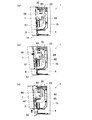
(a)は、本発明の実施形態にかかる室内機の停止時の斜視図であり、(b)は、室内機の運転時の斜視図であり、(c)は、室内機から前面パネル及び吹出パネルを取り外したときの斜視図である。(A) is a perspective view at the time of the stop of the indoor unit concerning the embodiment of the present invention, (b) is a perspective view at the time of operation of an indoor unit, (c) is a front panel and It is a perspective view when the blowing panel is removed.
(a)は、室内機の停止時の正面図であり、(b)は、室内機の運転時の正面図である。(A) is a front view at the time of a stop of an indoor unit, (b) is a front view at the time of operation of an indoor unit.
(a)は、室内機の停止時の右側面図であり、(b)は、室内機の運転時の右側面図である。(A) is a right side view when the indoor unit is stopped, and (b) is a right side view when the indoor unit is in operation.
室内機から前面パネル及び吹出パネルを取り外したときの正面図である。It is a front view when the front panel and the blowing panel are removed from the indoor unit.
室内機の縦断面を示す概略図である。It is the schematic which shows the longitudinal cross-section of an indoor unit.
室内機の制御部を示すブロック図である。It is a block diagram which shows the control part of an indoor unit.
(a)は、室内機の停止時の上面図であり、(b)は、室内機の運転時の上面図である。(A) is a top view when the indoor unit is stopped, and (b) is a top view when the indoor unit is in operation.
室内機の停止時の下面図である。It is a bottom view at the time of a stop of an indoor unit.
(a)は、天面部を示す概略図であり、(b)は、風向変更板単体の正面図である。(A) is the schematic which shows a top | upper surface part, (b) is a front view of a wind direction change board single-piece | unit.
天面部、クロスフローファン、風向変更板の位置関係を説明する説明図である。It is explanatory drawing explaining the positional relationship of a top | upper surface part, a cross flow fan, and a wind direction change board.
室内機から前面パネル及び吹出パネルを取り外したときの右側面図である。It is a right view when the front panel and the blowing panel are removed from the indoor unit.
(a)は、図4のA部拡大図であり、(b)は、(a)からねじを取り外したときの図であり、(c)は、図4に示すXII(c)-XII(c)線断面図である。(A) is the A section enlarged view of FIG. 4, (b) is a figure when a screw is removed from (a), (c) is XII (c) -XII ( c) It is a sectional view taken along the line.
(a)は、前面パネル及び吹出パネルの正面図、(b)は、XIII(b)-XIII(b)線断面図であり、(c)は、XIII(c)-XIII(c)線断面図であり、(d)は、XIII(d)-XIII(d)線断面図である。(A) is a front view of a front panel and a blowout panel, (b) is a sectional view taken along line XIII (b) -XIII (b), and (c) is a sectional view taken along line XIII (c) -XIII (c). (D) is a sectional view taken along line XIII (d) -XIII (d).
図2に示すXIV-XIV線断面図である。It is the XIV-XIV sectional view taken on the line shown in FIG.
図2に示すXV-XV線断面図であって、駆動機構の構成を示す図である。FIG. 3 is a cross-sectional view taken along line XV-XV shown in FIG. 2 and shows a configuration of a drive mechanism.
前面パネル及び吹出パネルの移動の様子を説明した図であり、(a)は、前面パネルの移動前の様子を示し、(b)は、前面パネルが移動した後の様子を示し、(c)は、前面パネル及び吹出パネルが移動した後の様子を示す。It is the figure explaining the mode of a movement of a front panel and a blow-out panel, (a) shows a mode before movement of a front panel, (b) shows a mode after a front panel moved, (c) Shows a state after the front panel and the blowout panel have moved.
以下、本発明の実施形態に係る空気調和機の室内機について説明する。
Hereinafter, an indoor unit of an air conditioner according to an embodiment of the present invention will be described.
[空気調和機の全体構成]
本発明の実施形態にかかる空気調和機は、図1に示す室内機1と、図示しない室外機とで構成されている。室内機1は、全体として一方向に細長い形状をしており、その長手方向が水平となるように室内の壁面に据え付けられている。なお、以下の説明において、室内機1が取り付けられる壁面から突出する方向を「前方」と称し、その反対の方向を「後方」と称する。また、図1に示す左右方向を単に「左右方向」、図1に示す上下方向を単に「上下方向」と称する。
[Overall configuration of air conditioner]
An air conditioner according to an embodiment of the present invention includes an indoor unit 1 shown in FIG. 1 and an outdoor unit (not shown). The indoor unit 1 has an elongated shape in one direction as a whole, and is installed on the wall surface of the room so that its longitudinal direction is horizontal. In the following description, the direction protruding from the wall surface to which the indoor unit 1 is attached is referred to as “front”, and the opposite direction is referred to as “rear”. Further, the left-right direction shown in FIG. 1 is simply referred to as “left-right direction”, and the up-down direction shown in FIG. 1 is simply referred to as “up-down direction”.
[室内機の構成]
図5に示すように、室内機1は、主として、本体部4、前面パネル7、吹出パネル8、風向変更板50などを備えている。
[Configuration of indoor unit]
As shown in FIG. 5, the indoor unit 1 mainly includes a main body 4, a front panel 7, a blowout panel 8, a wind direction changing plate 50, and the like.
[本体部]
本体部4は、図4及び図5に示すように、底フレーム42及び前面グリル6を含むケーシング5と、ケーシング5の内部に収容された室内熱交換器20、クロスフローファン21(以下、単にファン21とも称する)、ファンモータ22(図6参照)、電装品箱40を有する。
[Main unit]
As shown in FIGS. 4 and 5, the main body 4 includes a casing 5 including a bottom frame 42 and a front grille 6, an indoor heat exchanger 20 housed in the casing 5, and a cross flow fan 21 (hereinafter simply referred to as a “main flow”). A fan motor 22 (see FIG. 6), and an electrical component box 40.
室内熱交換器20及びファン21は、図5に示すように、底フレーム42に取り付けられている。室内熱交換器20及びファン21は、断面視においてファン21が室内機1の略中央に配置され、逆V字型の形状を有する室内熱交換器20がファン21の上半分を囲むように配置されている。
The indoor heat exchanger 20 and the fan 21 are attached to the bottom frame 42 as shown in FIG. The indoor heat exchanger 20 and the fan 21 are arranged so that the fan 21 is arranged at substantially the center of the indoor unit 1 in a cross-sectional view, and the indoor heat exchanger 20 having an inverted V shape surrounds the upper half of the fan 21. Has been.
電装品箱40は、図4に示すように、室内熱交換器20及びファン21の正面視における右側方に配置されている。電装品箱40は、内部に制御部60(図6参照)を収容しており、室内機1の冷暖房運転等に必要な各構成部品の制御を行う。この制御部60は、図6に示すように、ファン21を駆動するファンモータ22、後述する駆動機構9の駆動機41を駆動する駆動モータ43、風向変更板50を駆動するフラップモータ51、後述する補助風向変更板52を駆動する補助フラップモータ53を接続しており、ファン21、駆動機41、風向変更板50及び補助風向変更板52の制御を行う。
As shown in FIG. 4, the electrical component box 40 is disposed on the right side in the front view of the indoor heat exchanger 20 and the fan 21. The electrical component box 40 houses a control unit 60 (see FIG. 6), and controls each component necessary for the air conditioning operation of the indoor unit 1 and the like. As shown in FIG. 6, the control unit 60 includes a fan motor 22 that drives the fan 21, a drive motor 43 that drives a drive machine 41 of the drive mechanism 9 described later, a flap motor 51 that drives a wind direction changing plate 50, and The auxiliary flap motor 53 for driving the auxiliary wind direction changing plate 52 is connected, and the fan 21, the drive device 41, the wind direction changing plate 50, and the auxiliary wind direction changing plate 52 are controlled.
底フレーム42は、樹脂材料で成形されており、ファン21の下方、後方、側方を覆う形状を有している。この底フレーム42は、室内熱交換器20及びファン21を固定し且つ室内機1の背面1bを構成する図示しない本体ケーシングと、本体ケーシングの左右両端に取り付けられ、前面グリル6とともに室内機1の側面を構成する化粧板47(図3参照)とを有する。本体ケーシングの背面には、室内機1を室内の壁面に固定するための据付板が取り付けられている。
The bottom frame 42 is formed of a resin material and has a shape that covers the lower side, the rear side, and the side of the fan 21. The bottom frame 42 is fixed to the main body casing (not shown) that fixes the indoor heat exchanger 20 and the fan 21 and constitutes the back surface 1b of the indoor unit 1, and the left and right ends of the main body casing. It has a decorative plate 47 (see FIG. 3) constituting the side surface. An installation plate for fixing the indoor unit 1 to the indoor wall surface is attached to the back surface of the main casing.
底フレーム42は、その下部において、前面グリル6とともに吹出口27を構成する。この吹出口27は、ファン21からの風を室内へと吹き出す開口である。この吹出口27は、室内機1の下部近傍であって、室内機1の前面側に設けられている。この吹出口27は、図2(b)に示すように、正面視において水平方向に長い形状を有する。
The bottom frame 42 constitutes the air outlet 27 together with the front grill 6 at the lower part thereof. This blower outlet 27 is an opening for blowing the wind from the fan 21 into the room. The air outlet 27 is provided near the lower portion of the indoor unit 1 and on the front side of the indoor unit 1. As shown in FIG. 2B, the air outlet 27 has a shape that is long in the horizontal direction when viewed from the front.
[前面グリル]
前面グリル6は、前方から底フレーム42に取り付けられ、本体部4の前方、側方、上方、下方を覆う。前面グリル6は、樹脂材料で成形されており、背面全体が開口した薄型の略直方体形状を有する。この前面グリル6は、図4に示すように、天面部30と、前面31(ケーシングの前面)と、下面32とを有する。
[Front grille]
The front grill 6 is attached to the bottom frame 42 from the front, and covers the front, side, upper, and lower sides of the main body 4. The front grill 6 is formed of a resin material and has a thin, substantially rectangular parallelepiped shape with the entire back surface opened. As shown in FIG. 4, the front grill 6 has a top surface portion 30, a front surface 31 (front surface of the casing), and a lower surface 32.
(天面部)
天面部30は、図9(a)に示すように、その前端30Fの中央部30Mが前方に膨出するように湾曲している。詳しくは、天面部30の前端30Fは、前端30Fの中央部30Mから両端30a、30bに向かうにつれて背面1b側に傾斜しているとともに、平面視において天面部30の前端30Fに接する接線の向きが連続的に変化するように湾曲している。また、天面部30の側端30L、30Rは、それぞれ両端30a、30bから背面1bに向かうにつれて室内機1の長手方向(左右方向)中心側に傾斜(湾曲)している。
(Top)
As shown in FIG. 9A, the top surface portion 30 is curved so that the central portion 30M of the front end 30F bulges forward. Specifically, the front end 30F of the top surface portion 30 is inclined to the back surface 1b side from the central portion 30M of the front end 30F toward both ends 30a and 30b, and the direction of the tangent line in contact with the front end 30F of the top surface portion 30 in plan view is Curved to change continuously. Further, the side ends 30L and 30R of the top surface portion 30 are inclined (curved) toward the center side in the longitudinal direction (left and right direction) of the indoor unit 1 from the both ends 30a and 30b toward the back surface 1b.
この天面部30の略全面には、室内空気の第1吸込口23(吸込口)が配置される。この第1吸込口23の略全面には、図7(a)に示すように、長手方向及び前後方向に延びた複数の桟30cが配置されている。この第1吸込口23の下方(室内機1の内部側)には、長手方向中央部に形成された開口部24と、開口部24の長手方向外側に配置された非開口部25とを有する。開口部24においては、桟30cと桟30cとの間が開口しており、非開口部25においては、桟30cと桟30cとの間に桟30cと桟30cとの間を閉塞する板材30dが配置されている。この板材30dは、天面部30の外縁より下方(すなわち、第1吸込口23より室内機1の内部側)に配置される。したがって、第1吸込口23から吸い込まれる室内空気は、直接開口部24からファン21側に取り込まれる場合と、第1吸込口23から吸い込まれたあとで、いったん非開口部25の板材30dの上を水平方向に流れたのち、開口部24からファン21側に取り込まれる場合とがある。
A first air inlet 23 (suction port) for indoor air is disposed on substantially the entire top surface 30. As shown in FIG. 7A, a plurality of crosspieces 30c extending in the longitudinal direction and the front-rear direction are arranged on substantially the entire surface of the first suction port 23. Below the first suction port 23 (inside the indoor unit 1), there is an opening 24 formed in the center in the longitudinal direction and a non-opening 25 disposed outside the opening 24 in the longitudinal direction. . In the opening 24, a space between the crosspiece 30c is formed between the crosspiece 30c. In the non-opening 25, a plate member 30d for closing the crosspiece 30c and the crosspiece 30c is provided between the crosspiece 30c and the crosspiece 30c. Has been placed. The plate member 30d is disposed below the outer edge of the top surface portion 30 (that is, on the inner side of the indoor unit 1 from the first suction port 23). Therefore, the indoor air sucked from the first suction port 23 is directly taken into the fan 21 side from the opening 24, and after being sucked from the first suction port 23, the room air is once on the plate 30d of the non-opening 25. May flow into the fan 21 side from the opening 24 after flowing in the horizontal direction.
図9(a)に示すように、第1吸込口23は、長手方向について天面部30の前端30Fの中央部30Mに対応した吸込中央部23Mの幅W1が、第1吸込口23の長手方向両端の幅、すなわち、本実施形態では、天面部30の左端30a付近の幅、及び天面部30の右端30b付近の幅よりも広く構成される。本実施形態では、天面部30の左端30a付近の幅、及び天面部30の右端30b付近の幅は、僅か(略ゼロ)である。この第1吸込口23の幅は、吸込中央部23Mにおいて最大である。また、第1吸込口23の幅は、吸込中央部23Mから長手方向両端30a、30bに近づくにつれて狭くなる。なお、図9(a)では、発明の理解を容易とするため、長手方向及び前後方向に延びた複数の桟30cを省略して図示している。
As shown in FIG. 9A, the first suction port 23 has a width W1 of the suction center portion 23M corresponding to the center portion 30M of the front end 30F of the top surface portion 30 in the longitudinal direction. The width of both ends, that is, the width in the vicinity of the left end 30a of the top surface portion 30 and the width in the vicinity of the right end 30b of the top surface portion 30 are configured wider in this embodiment. In the present embodiment, the width of the top surface portion 30 near the left end 30a and the width of the top surface portion 30 near the right end 30b are slightly (substantially zero). The width of the first suction port 23 is maximum at the suction center portion 23M. Moreover, the width | variety of the 1st suction inlet 23 becomes narrow as it approaches the longitudinal direction both ends 30a and 30b from the suction center part 23M. In FIG. 9A, in order to facilitate understanding of the invention, a plurality of bars 30c extending in the longitudinal direction and the front-rear direction are omitted.
図9(a)に示すように、開口部24は、その前端24Fが、天面部30の前端30Fに沿っている。そして、開口部24は、長手方向について天面部30の前端30Fの中央部30Mに対応した開口中央部24Mの幅が、開口部24の両端の幅(開口部の左端24Lの幅、開口部24の右端24Rの幅)より広く構成される。なお、図10に示すように、天面部30の下方にある開口部24の長手方向中央部は、長手方向について天面部30の前端30Fの中央部30Mに対応した吸込中央部23Mに対して僅かに左にずれており、ファン21の長手方向中央部及び風向変更板50の長手方向中央部と一致する。また、開口部24の両端24L、24Rは、ファン21の両端及び風向変更板50の両端50L、50Rと略一致する。
As shown in FIG. 9A, the front end 24 </ b> F of the opening 24 is along the front end 30 </ b> F of the top surface portion 30. The width of the opening center portion 24M corresponding to the center portion 30M of the front end 30F of the top surface portion 30 in the longitudinal direction is equal to the width of both ends of the opening portion 24 (the width of the left end 24L of the opening portion, the opening portion 24). Of the right end 24R). As shown in FIG. 10, the central portion in the longitudinal direction of the opening 24 below the top surface portion 30 is slightly smaller than the suction central portion 23M corresponding to the central portion 30M of the front end 30F of the top surface portion 30 in the longitudinal direction. And is aligned with the longitudinal center of the fan 21 and the longitudinal center of the wind direction changing plate 50. Further, both ends 24L and 24R of the opening 24 substantially coincide with both ends of the fan 21 and both ends 50L and 50R of the wind direction changing plate 50.
(前面)
前面31(ケーシングの前面)は、図4に示すように、正面視において左右方向に長い略長方形の形状を有する。この前面31は、図1(c)から容易に理解されるように、前面グリル6の前面31の長手方向両端近傍(ケーシングの前面の長手方向両端近傍)に配置される近傍面33、33が、長手方向中央部に近づくにつれて奥行寸法が大きくなるように湾曲している。また、この近傍面33、33は、下方に向かうにつれて背面1b側に傾斜(湾曲)している。この前面31は、上記の近傍面33、33の他、天面部30の前端30F、室内空気を取り入れる開口34、吹出口27周囲に配置される吹出口周辺部35などを含む。
(Front)
As shown in FIG. 4, the front surface 31 (front surface of the casing) has a substantially rectangular shape that is long in the left-right direction when viewed from the front. As can be easily understood from FIG. 1 (c), the front surface 31 has adjacent surfaces 33, 33 arranged in the vicinity of both ends in the longitudinal direction of the front surface 31 of the front grill 6 (in the vicinity of both ends in the longitudinal direction of the front surface of the casing). It is curved so that the depth dimension increases as it approaches the central portion in the longitudinal direction. Further, the neighboring surfaces 33 and 33 are inclined (curved) toward the back surface 1b as going downward. The front surface 31 includes, in addition to the above-described neighboring surfaces 33 and 33, a front end 30F of the top surface portion 30, an opening 34 for taking in indoor air, an air outlet peripheral portion 35 disposed around the air outlet 27, and the like.
開口34は、図4に示すように、前面31の上下方向中央付近から上部に渡って設けられ、室内熱交換器20の前面側と対向する。この開口34は、左右方向に長い矩形形状を有し、図11に示すように、鉛直方向に延びている。したがって、開口34は、同一平面上にある。この開口34は、開口部24の前端24F側から取り入れられた室内空気や、後述する第2吸込口26から取り入れられた室内空気をファン21側に取り込む。この開口34の前方には、開口34の略全域を覆うフィルタ36(図5参照)が取り付けられている。このフィルタ36は、図5に示すように、室内熱交換器20の前方側から上方側まで延在しており、第1吸込口23及び第2吸込口26から取り入れられた室内空気中の塵埃を捕集する。
As shown in FIG. 4, the opening 34 is provided from the vicinity of the center in the vertical direction of the front surface 31 to the upper portion, and faces the front surface side of the indoor heat exchanger 20. The opening 34 has a rectangular shape that is long in the left-right direction, and extends in the vertical direction as shown in FIG. Therefore, the opening 34 is on the same plane. The opening 34 takes in indoor air taken in from the front end 24F side of the opening 24 or indoor air taken in from a second suction port 26 described later to the fan 21 side. A filter 36 (see FIG. 5) that covers substantially the entire area of the opening 34 is attached in front of the opening 34. As shown in FIG. 5, the filter 36 extends from the front side to the upper side of the indoor heat exchanger 20, and dust in indoor air taken in from the first suction port 23 and the second suction port 26. To collect.
吹出口周辺部35は、図1(c)に示すように、その長手方向中央部が前方に膨出するように湾曲している。詳しくは、吹出口周辺部35の両端から長手方向中央部に近づくにつれて奥行寸法が大きくなるように湾曲している。
As shown in FIG. 1C, the blower outlet peripheral portion 35 is curved so that the central portion in the longitudinal direction swells forward. In detail, it curves so that a depth dimension may become large as it approaches the longitudinal direction center part from the both ends of the blower outlet peripheral part 35. FIG.
図1(a)などから理解されるように、室内機1の運転停止時には、前面パネル7は、天面部30の前端30Fや近傍面33、33の一部(上側)と当接又は近接している。したがって、前面31の上側は、前面パネル7によって閉じられた状態となる。また、吹出パネル8は、吹出口周辺部35や近傍面33、33の一部(下側)と当接又は近接している。したがって、前面31の下側は、吹出パネル8によって閉じられた状態となる。一方、室内機1の運転時には、図1(b)に示すように、前面パネル7が略水平方向前方に移動することで、前面パネル7と天面部30の前端30Fや近傍面33、33との間に隙間が生じ、室内空気を吸い込む第2吸込口26が形成される。また、吹出パネル8が前面パネル7と前面グリル6との間に移動することで、吹出口27が開かれる。
As understood from FIG. 1A and the like, when the operation of the indoor unit 1 is stopped, the front panel 7 is in contact with or close to a part of the front end 30F of the top surface 30 and the vicinity surfaces 33 and 33 (upper side). ing. Therefore, the upper side of the front surface 31 is closed by the front panel 7. Further, the blowout panel 8 is in contact with or close to a part (lower side) of the blower outlet peripheral portion 35 and the neighboring surfaces 33 and 33. Therefore, the lower side of the front surface 31 is closed by the blowout panel 8. On the other hand, when the indoor unit 1 is in operation, as shown in FIG. 1 (b), the front panel 7 moves forward in a substantially horizontal direction, so that the front panel 30 and the front end 30 </ b> F of the top surface 30 and the adjacent surfaces 33 and 33 A gap is formed between the two, and a second suction port 26 for sucking room air is formed. Moreover, the blower outlet 27 is opened when the blowout panel 8 moves between the front panel 7 and the front grille 6.
図4に示すように、前面31の長手方向両端近傍に配置される近傍面33、33の上端側には、近傍面33、33(前面グリル6の前面31)より背面側に窪んだ2つの凹部91、91が形成されている。この2つの凹部91、91は左右対称である。図12に示すように、この凹部91には、前面グリル6を底フレーム42に固定するためのねじSが螺合されるねじ固定部92(ねじ孔)が形成されている。また、凹部91には、ねじ固定部92の左右方向外側において近傍面33、33(前面グリルの前面)より前方に突出する突出部93が配置されている。したがって、この室内機1では、室内機1の側方や斜め前方からねじSが見えにくいようにされている。
As shown in FIG. 4, there are two recesses recessed on the back side from the neighboring surfaces 33, 33 (the front surface 31 of the front grill 6) on the upper side of the neighboring surfaces 33, 33 arranged near both longitudinal ends of the front surface 31. Concave portions 91 and 91 are formed. The two recesses 91 and 91 are symmetrical. As shown in FIG. 12, a screw fixing portion 92 (screw hole) into which a screw S for fixing the front grill 6 to the bottom frame 42 is screwed is formed in the recess 91. Further, in the concave portion 91, a protruding portion 93 that protrudes forward from the adjacent surfaces 33 and 33 (the front surface of the front grille) is disposed on the outer side in the left-right direction of the screw fixing portion 92. Therefore, in this indoor unit 1, the screw S is made difficult to be seen from the side of the indoor unit 1 or obliquely forward.
前面31の下方及び下面32の前方には、底フレーム42とともに吹出口27を形成するための開口が形成されている。この吹出口27の前面は、室内機1の運転停止時において吹出パネル8によって閉じられる。また、吹出口27の下面は、図8に示すように、室内機1の運転停止時において、底フレーム42に取り付けられた風向変更板50によって閉じられる。
An opening for forming the air outlet 27 together with the bottom frame 42 is formed below the front surface 31 and in front of the lower surface 32. The front surface of the air outlet 27 is closed by the air outlet panel 8 when the operation of the indoor unit 1 is stopped. Further, as shown in FIG. 8, the lower surface of the air outlet 27 is closed by a wind direction changing plate 50 attached to the bottom frame 42 when the operation of the indoor unit 1 is stopped.
図2(b)に示すように、吹出口27には、風向変更板50と、風向変更板50の上方に配置された補助風向変更板52とが配置される。風向変更板50および補助風向変更板52は、左右方向に長い形状を有する板状の形状を有しており、風向変更板50および補助風向変更板52は、それぞれ異なる水平方向に沿った回転軸の周りを回動可能に構成される。したがって、風向変更板50は、補助風向変更板52とともに、上下方向において吹出口27から吹き出される空気の風向を変更する。風向変更板50には、フラップモータ51が接続されており、補助風向変更板52には、補助フラップモータ53が接続されている。風向変更板50および補助風向変更板52は、フラップモータ51及び補助フラップモータ53の駆動により、それぞれ異なる水平方向に沿った回転軸の周りを回動可能である。
As shown in FIG. 2B, a wind direction changing plate 50 and an auxiliary wind direction changing plate 52 arranged above the wind direction changing plate 50 are arranged at the outlet 27. The wind direction changing plate 50 and the auxiliary wind direction changing plate 52 have a plate-like shape having a long shape in the left-right direction, and the wind direction changing plate 50 and the auxiliary wind direction changing plate 52 are rotational axes along different horizontal directions. It is comprised so that rotation around is possible. Therefore, the wind direction change board 50 changes the wind direction of the air which blows off from the blower outlet 27 in an up-down direction with the auxiliary | assistant wind direction change board 52. FIG. A flap motor 51 is connected to the wind direction changing plate 50, and an auxiliary flap motor 53 is connected to the auxiliary wind direction changing plate 52. The wind direction changing plate 50 and the auxiliary wind direction changing plate 52 can be rotated around different rotation axes by driving the flap motor 51 and the auxiliary flap motor 53, respectively.
風向変更板50は、図9(b)及び図10に示すように、その前端50Fの中央付近が前方に膨出するように湾曲している。詳しくは、風向変更板50の前端50Fは、天面部30の前端30Fの中央部30Mに対応した吹出中央部50M(図1(c)、図2(b)も併せて参照)から両端50a、50bに向かうにつれて背面1b側に傾斜しているとともに、平面視において風向変更板50の前端50Fに接する接線の向きが連続的に変化するように湾曲している。また、風向変更板50の側端50L、50Rは、それぞれ前後方向に沿って延在している。この風向変更板50は、天面部30の前端30Fの中央部30Mに対応した吹出中央部50Mの幅W2が、長手方向両端の幅(左端50Lの幅、右端50Rの幅)より広く構成される。この風向変更板50の幅は、吹出中央部50Mにおいて最大である。また、風向変更板50の幅は、吹出中央部50Mから長手方向両端50a、50bに近づくにつれて狭くなる。この風向変更板50は、図8に示すように、室内機1の運転停止時において、吹出パネル8及び前面グリル6の下面32により画定される開口に沿った形状をしている。そして、風向変更板50は、運転停止指示があった時に、水平面に平行になるように移動することにより、前面グリル6の下面32とともに水平面に平行な室内機1の底面を構成する。なお、図10に示すように、風向変更板50の長手方向中央部は、長手方向について天面部30の前端30Fの中央部30Mに対応した吹出中央部50Mに対して僅かに左にずれており、ファン21の長手方向中央部及び開口部24の長手方向中央部と一致する。風向変更板50の長手方向中央部の幅W3は、長手方向両端の幅(左端50Lの幅、右端50Rの幅)より広く構成される。
As shown in FIGS. 9B and 10, the wind direction changing plate 50 is curved so that the vicinity of the center of the front end 50 </ b> F bulges forward. Specifically, the front end 50F of the wind direction changing plate 50 has both ends 50a from the blowout center portion 50M (see also FIGS. 1C and 2B) corresponding to the center portion 30M of the front end 30F of the top surface portion 30. As it goes to 50b, it inclines to the back surface 1b side and is curved so that the direction of the tangent line in contact with the front end 50F of the wind direction changing plate 50 changes continuously in plan view. Further, the side ends 50L and 50R of the wind direction changing plate 50 extend along the front-rear direction. The wind direction changing plate 50 is configured such that the width W2 of the blowout central portion 50M corresponding to the central portion 30M of the front end 30F of the top surface portion 30 is wider than the width at both ends in the longitudinal direction (the width of the left end 50L and the width of the right end 50R). . The width of the wind direction changing plate 50 is maximum at the blowout central portion 50M. Moreover, the width | variety of the wind direction change board 50 becomes narrow as it approaches the longitudinal direction both ends 50a and 50b from the blowing center part 50M. As shown in FIG. 8, the wind direction changing plate 50 has a shape along an opening defined by the blowout panel 8 and the lower surface 32 of the front grill 6 when the operation of the indoor unit 1 is stopped. And the wind direction change board 50 comprises the bottom face of the indoor unit 1 parallel to a horizontal surface with the lower surface 32 of the front grill 6 by moving so that it may become parallel to a horizontal surface, when operation stop instruction | indication is carried out. As shown in FIG. 10, the longitudinal direction central portion of the wind direction changing plate 50 is slightly shifted to the left with respect to the blowout central portion 50M corresponding to the central portion 30M of the front end 30F of the top surface portion 30 in the longitudinal direction. , Which coincides with the longitudinal center of the fan 21 and the longitudinal center of the opening 24. The width W3 of the central portion in the longitudinal direction of the wind direction changing plate 50 is configured wider than the widths at both ends in the longitudinal direction (the width of the left end 50L and the width of the right end 50R).
一方、補助風向変更板52は、図2(b)に示すように、その幅が長手方向に一定である。このように、補助風向変更板52の幅が長手方向に一定であるので、風向変更板50および補助風向変更板52がそれぞれ異なる水平方向に沿った回転軸の周りを回動する際に、風向変更板50および補助風向変更板52が互いに干渉することがないようにされている。
On the other hand, as shown in FIG. 2B, the auxiliary wind direction changing plate 52 has a constant width in the longitudinal direction. Thus, since the width of the auxiliary wind direction changing plate 52 is constant in the longitudinal direction, the wind direction is changed when the wind direction changing plate 50 and the auxiliary wind direction changing plate 52 rotate around the rotation axes along different horizontal directions. The change plate 50 and the auxiliary wind direction change plate 52 are configured not to interfere with each other.
[前面パネル及び吹出パネル]
前面パネル7及び吹出パネル8は、図1(a)に示すように、室内機1の運転停止時において、前面グリル6の前面31の略全体を覆う。
[Front panel and blowout panel]
As shown in FIG. 1A, the front panel 7 and the blowout panel 8 cover substantially the entire front surface 31 of the front grill 6 when the operation of the indoor unit 1 is stopped.
前面パネル7は、樹脂材料で成形されており、前面グリル6の前面31の上方を覆うように設けられる。前面パネル7は、後述する開閉機構61によって前後方向に移動可能に左右両端近傍を支持されている。この前面パネル7は、前面グリル6の前面31から離れるように移動することによって第2吸込口26を開き、前面グリル6の前面31に近接するように移動することによって第2吸込口26を閉じる。
The front panel 7 is formed of a resin material and is provided so as to cover the upper side of the front surface 31 of the front grill 6. The front panel 7 is supported near the left and right ends so as to be movable in the front-rear direction by an opening / closing mechanism 61 described later. The front panel 7 opens the second suction port 26 by moving away from the front surface 31 of the front grill 6, and closes the second suction port 26 by moving closer to the front surface 31 of the front grill 6. .
吹出パネル8は、樹脂材料で成形されており、前面グリル6の前面31の下方を覆うように設けられる。吹出パネル8は、後述する開閉機構61によって上下方向に移動可能に左右両端近傍を支持されている。この吹出パネル8は、前面パネル7が前方へ移動した状態において、前面パネル7と前面グリル6の間の隙間に移動(上方に移動)することによって吹出口27を開き、下方に移動することによって吹出口27を閉じる。
The blowout panel 8 is formed of a resin material, and is provided so as to cover the lower portion of the front surface 31 of the front grill 6. The blow-out panel 8 is supported in the vicinity of both left and right ends so as to be movable in the vertical direction by an opening / closing mechanism 61 described later. When the front panel 7 is moved forward, the blow-out panel 8 moves (moves upward) into the gap between the front panel 7 and the front grill 6 to open the air outlet 27 and moves downward. The outlet 27 is closed.
(パネル形状)
前面パネル7及び吹出パネル8は、3次元形状を有する3次元パネルである。すなわち、長手方向(左右方向)において湾曲し且つ上下方向において湾曲している。この前面パネル7の厚み及び吹出パネル8の厚みは、長手方向及び上下方向において略一定であり、前面パネル7の厚みと吹出パネル8の厚みは略同じである。なお、前面パネル7及び吹出パネル8には、その裏面の外周略全周に、裏面から後方に突出した補強リブ7a、8a(図13(d)参照)が設けられている。
(Panel shape)
The front panel 7 and the blowout panel 8 are three-dimensional panels having a three-dimensional shape. That is, it is curved in the longitudinal direction (left-right direction) and curved in the up-down direction. The thickness of the front panel 7 and the thickness of the blowing panel 8 are substantially constant in the longitudinal direction and the vertical direction, and the thickness of the front panel 7 and the thickness of the blowing panel 8 are substantially the same. The front panel 7 and the blowout panel 8 are provided with reinforcing ribs 7a and 8a (see FIG. 13 (d)) protruding rearward from the back surface on substantially the entire outer periphery of the back surface.
前面パネル7は、図13(b)に示すように、平面視において、その中央部7Mが前方に膨出するように湾曲している。詳しくは、前面パネル7の前面7F(前面部)は、前面パネル7の前面7Fの中央部7Mから長手方向両端に向かうにつれて背面1b側に傾斜しているとともに、平面視において前面パネル7の前面7Fに接する接線の向きが連続的に変化するように湾曲している。すなわち、前面パネル7は、長手方向全域において湾曲している。
As shown in FIG. 13B, the front panel 7 is curved so that the central portion 7M bulges forward in plan view. Specifically, the front surface 7F (front surface portion) of the front panel 7 is inclined to the back surface 1b side from the center portion 7M of the front surface 7F of the front panel 7 toward both ends in the longitudinal direction, and in front view, the front surface of the front panel 7 It is curved so that the direction of the tangent line in contact with 7F changes continuously. That is, the front panel 7 is curved in the entire longitudinal direction.
この前面パネル7は、図13(d)に示すように、前面パネル7の前面7Fの上端7Faが最も前方に位置しており、前面パネル7の前面7F(前面部)は、下端1aに向かうにつれて背面1b側に傾斜している。また、前面パネル7は上下方向において厚みが一定であるので、前面パネル7全体も下端1aに向かうにつれて背面1b側に傾斜している。また、この前面パネル7は、前方側が凸となるように、断面視において前面パネル7の前面7Fに接する接線の向きが連続的に変化するように湾曲している。すなわち、前面パネル7は、上下方向全域において湾曲している。
In the front panel 7, as shown in FIG. 13D, the upper end 7Fa of the front surface 7F of the front panel 7 is located at the foremost side, and the front surface 7F (front surface portion) of the front panel 7 faces the lower end 1a. Accordingly, it is inclined toward the back surface 1b. Further, since the thickness of the front panel 7 is constant in the vertical direction, the entire front panel 7 is also inclined toward the back surface 1b side toward the lower end 1a. Further, the front panel 7 is curved so that the direction of the tangent line in contact with the front surface 7F of the front panel 7 changes continuously in a cross-sectional view so that the front side is convex. That is, the front panel 7 is curved in the entire vertical direction.
この前面パネル7のうち前面グリル6の天面部30の前端30Fに対向する部分は、前端30Fに沿って湾曲している。また、この前面パネル7のうち前面グリル6の近傍面33、33に対向する部分は、長手方向及び上下方向において近傍面33、33に沿って湾曲している。したがって、室内機1の運転停止時においては、前面パネル7と前端30F及び近傍面33、33との間には、隙間がほとんど生じない。
A portion of the front panel 7 facing the front end 30F of the top surface portion 30 of the front grill 6 is curved along the front end 30F. Moreover, the part which opposes the near surfaces 33 and 33 of the front grille 6 among this front panel 7 is curving along the near surfaces 33 and 33 in a longitudinal direction and an up-down direction. Therefore, when the operation of the indoor unit 1 is stopped, there is almost no gap between the front panel 7, the front end 30F, and the adjacent surfaces 33 and 33.
吹出パネル8は、図13(c)に示すように、平面視において、その中央部8Mが前方に膨出するように湾曲している。詳しくは、吹出パネル8の前面8Fは、吹出パネル8の前面8Fの中央部8Mから長手方向両端に向かうにつれて背面1b側に傾斜しているとともに、平面視において吹出パネル8の前面8Fに接する接線の向きが連続的に変化するように湾曲している。すなわち、吹出パネル8は、長手方向全域において湾曲している。
As shown in FIG. 13C, the blowout panel 8 is curved so that the central portion 8M bulges forward in plan view. Specifically, the front surface 8F of the blowout panel 8 is inclined toward the back surface 1b as it goes from the central portion 8M of the front face 8F of the blowout panel 8 toward both ends in the longitudinal direction, and is tangent to the front face 8F of the blowout panel 8 in plan view. It is curved so that its direction changes continuously. That is, the blowing panel 8 is curved in the entire longitudinal direction.
この吹出パネル8は、図13(d)に示すように、吹出パネル8の前面8Fの上端8Faが最も前方に位置しており、吹出パネル8の前面8Fは、下端1aに向かうにつれて背面1b側に傾斜している。また、吹出パネル8は上下方向において厚みが一定であるので、吹出パネル8全体も下端1aに向かうにつれて背面1b側に傾斜している。また、この吹出パネル8は、前方側が凸となるように、断面視において吹出パネル8の前面8Fに接する接線の向きが連続的に変化するように湾曲している。すなわち、吹出パネル8は、上下方向全域において湾曲している。
As shown in FIG. 13 (d), the blower panel 8 has the upper end 8Fa of the front face 8F of the blower panel 8 positioned at the foremost side, and the front face 8F of the blower panel 8 is closer to the rear face 1b toward the lower end 1a. It is inclined to. Moreover, since the blowing panel 8 has a constant thickness in the vertical direction, the entire blowing panel 8 is also inclined toward the back surface 1b as it goes toward the lower end 1a. Further, the blowout panel 8 is curved so that the direction of the tangent line in contact with the front surface 8F of the blowout panel 8 continuously changes in a sectional view so that the front side is convex. That is, the blowout panel 8 is curved in the entire vertical direction.
この吹出パネル8のうち前面グリル6の近傍面33、33に対向する部分、及び前面グリル6の吹出口周辺部35に対向する部分は、長手方向及び上下方向において近傍面33、33及び吹出口周辺部35に沿って湾曲している。したがって、室内機1の運転停止時においては、吹出パネル8と近傍面33、33及び吹出口周辺部35との間には、隙間がほとんど生じない。
A portion of the blowout panel 8 that faces the vicinity surfaces 33 and 33 of the front grill 6 and a portion of the front grille 6 that faces the blower outlet peripheral portion 35 are arranged in the longitudinal direction and the vertical direction. Curved along the peripheral portion 35. Therefore, when the operation of the indoor unit 1 is stopped, there is almost no gap between the blowout panel 8 and the vicinity surfaces 33 and 33 and the blowout port peripheral portion 35.
(延在部分)
前面パネル7は、図1(a)及び図7(a)に示すように、前面グリル6の前面31の両端31L、31R(図4も併せて参照)より外側に向かって延在する延在部分71、71を有している。また、吹出パネル8も、図1(a)及び図8に示すように、前面グリル6の前面31の両端31L、31Rより外側に向かって延在する延在部分81、81を有している。延在部分71、71は、図7(a)に示すように、前面グリル6の前面31の両端31L、31Rを通る前後方向に沿った線L1より長手方向外側に延在した部分を指す。また、延在部分81、81は、図8に示すように、前面グリル6の前面31の両端31L、31Rを通る前後方向に沿った線L2より長手方向外側に延在した部分を指す。延在部分71、71は、左右対称に構成されており、延在部分81、81も、左右対称に構成されている。
(Extended part)
As shown in FIGS. 1A and 7A, the front panel 7 extends outward from both ends 31L and 31R (see also FIG. 4) of the front surface 31 of the front grill 6. There are portions 71, 71. The blowout panel 8 also has extended portions 81 and 81 that extend outward from both ends 31L and 31R of the front surface 31 of the front grill 6 as shown in FIGS. . As illustrated in FIG. 7A, the extending portions 71 and 71 indicate portions extending outward in the longitudinal direction from a line L1 along the front-rear direction passing through both ends 31L and 31R of the front surface 31 of the front grill 6. Moreover, the extension parts 81 and 81 point out the part extended in the longitudinal direction outer side from the line L2 along the front-back direction which passes both ends 31L and 31R of the front surface 31 of the front grille 6, as shown in FIG. The extending parts 71 and 71 are configured symmetrically, and the extending parts 81 and 81 are also configured symmetrically.
図7(a)及び図8に示すように、前面パネル7の延在部分71、71、及び吹出パネル8の延在部分81、81は、前面グリル6の前面31の両端31L、31Rからそれぞれ背面1b側に向かって延在している。また、延在部分71、71の先端部72、72、及び延在部分81、81の先端部82、82は、前方に屈曲している。なお、本発明において、「屈曲」とは「湾曲」を含む。
As shown in FIGS. 7A and 8, the extended portions 71 and 71 of the front panel 7 and the extended portions 81 and 81 of the blowout panel 8 are respectively formed from both ends 31 </ b> L and 31 </ b> R of the front surface 31 of the front grill 6. It extends toward the back surface 1b side. Moreover, the front-end | tip parts 72 and 72 of the extension parts 71 and 71 and the front-end | tip parts 82 and 82 of the extension parts 81 and 81 are bent ahead. In the present invention, “bending” includes “curving”.
ここで、図14を参照して、「延在部分71が前面グリル6の前面31の両端31L、31Rから背面1b側に向かって延在している」の定義、及び「延在部分71の先端部72が、前方に屈曲している」の定義について具体的に説明する。なお、「延在部分81が前面グリル6の前面31の両端31L、31Rから背面1b側に向かって延在している」の定義、及び「延在部分81の先端部82が、前方に屈曲している」の定義は、上記と同様であるためその説明を割愛する。
Here, with reference to FIG. 14, the definition of “the extending portion 71 extends from both ends 31 </ b> L and 31 </ b> R of the front surface 31 of the front grill 6 toward the back surface 1 b side” and “the extending portion 71 of the front portion 31. The definition of “the tip 72 is bent forward” will be specifically described. In addition, the definition that “the extending portion 81 extends from both ends 31L and 31R of the front surface 31 of the front grill 6 toward the back surface 1b” and “the front end portion 82 of the extending portion 81 is bent forward. The definition of “doing” is the same as above, and the explanation is omitted.
「延在部分71が前面グリル6の前面31の両端31L、31Rから背面1b側に向かって延在している」とは、図14に示すように、上述の線L1と前面パネル7の前面7Fとの交点7Fbを通る水平方向(左右方向)の線L3より、延在部分71の全体が背面1b側にあることを意味する。また、「延在部分71の先端部72が、前方に屈曲している」とは、平面視において、延在部分71の先端部72を除く部分の前面パネル7の中心線を左右方向外側に延在させた仮想線L4より、先端部72の中心線の少なくとも一部が前方側にあることを意味する。
“The extending portion 71 extends from both ends 31L and 31R of the front surface 31 of the front grill 6 toward the rear surface 1b” means that the above-described line L1 and the front surface of the front panel 7 are as shown in FIG. It means that the entire extending portion 71 is on the back surface 1b side from a horizontal (left-right) line L3 passing through the intersection 7Fb with 7F. Further, “the distal end portion 72 of the extending portion 71 is bent forward” means that the center line of the front panel 7 of the portion excluding the distal end portion 72 of the extending portion 71 is outward in the left-right direction in plan view. It means that at least part of the center line of the distal end portion 72 is on the front side from the extended virtual line L4.
[駆動機構]
駆動機構9は、前面パネル7を前面グリル6の前面31から離れるように略水平方向前方に移動させるとともに、前面パネル7が略水平方向前方に移動した状態において前面パネル7と前面グリル6の間の隙間に吹出パネル8を移動させる機構であり、図4に示すように、駆動機41と開閉機構61とを備えている。
[Drive mechanism]
The drive mechanism 9 moves the front panel 7 forward in a substantially horizontal direction so as to be away from the front surface 31 of the front grill 6, and between the front panel 7 and the front grill 6 in a state where the front panel 7 has moved forward in a substantially horizontal direction. As shown in FIG. 4, the mechanism includes a drive unit 41 and an opening / closing mechanism 61.
駆動機41は、図4に示すように、室内熱交換器20及びファン21の正面視における左側方に配置されており、前面パネル7及び吹出パネル8を移動させるための駆動力を発生させる。この駆動機41は、駆動モータ43(図6参照)と、図示しない複数の駆動機ギアを有している。駆動モータ43は、電装品箱40に収容される制御部60とケーブルによって接続され、前面パネル7及び吹出パネル8を移動させる駆動源となる。複数の駆動機ギアは、開閉機構61の図示しない動力伝達ギアと噛み合うように配置されており、駆動モータ43の回転を開閉機構61の動力伝達ギアに伝達して、開閉機構61に駆動モータ43の駆動力を伝達する。
As shown in FIG. 4, the driver 41 is disposed on the left side of the indoor heat exchanger 20 and the fan 21 in a front view, and generates a driving force for moving the front panel 7 and the blowout panel 8. The drive machine 41 has a drive motor 43 (see FIG. 6) and a plurality of drive machine gears (not shown). The drive motor 43 is connected to the control unit 60 accommodated in the electrical component box 40 by a cable and serves as a drive source for moving the front panel 7 and the blowout panel 8. The plurality of drive machine gears are arranged so as to mesh with a power transmission gear (not shown) of the opening / closing mechanism 61, and the rotation of the drive motor 43 is transmitted to the power transmission gear of the opening / closing mechanism 61, so that the drive motor 43 is transmitted to the opening / closing mechanism 61. The driving force is transmitted.
開閉機構61は、駆動機41の駆動力によって前面パネル7及び吹出パネル8を移動させて第2吸込口26および吹出口27を開閉するための機構である。開閉機構61は、ギア部を含む複数の部材によって構成されており、駆動機41の駆動力を前面パネル7及び吹出パネル8に伝達する減速機構として機能する。また、開閉機構61は、駆動機41から伝わる回転運動を前面パネル7及び吹出パネル8の開閉動作に変換する変換機構として機能する。図4に示すように、開閉機構61は、前面グリル6の左側方に設けられた第1開閉機構62と、前面グリル6の右側方に設けられた第2開閉機構63とを有する。第1開閉機構62と第2開閉機構63は、図示しない動力伝達軸によって接続されている。
The opening / closing mechanism 61 is a mechanism for opening and closing the second suction port 26 and the outlet 27 by moving the front panel 7 and the blowing panel 8 by the driving force of the driving machine 41. The opening / closing mechanism 61 is configured by a plurality of members including a gear portion, and functions as a speed reduction mechanism that transmits the driving force of the driving machine 41 to the front panel 7 and the blowout panel 8. The opening / closing mechanism 61 functions as a conversion mechanism that converts the rotational movement transmitted from the drive machine 41 into the opening / closing operation of the front panel 7 and the blowout panel 8. As shown in FIG. 4, the opening / closing mechanism 61 includes a first opening / closing mechanism 62 provided on the left side of the front grill 6 and a second opening / closing mechanism 63 provided on the right side of the front grill 6. The first opening / closing mechanism 62 and the second opening / closing mechanism 63 are connected by a power transmission shaft (not shown).
第1開閉機構62は、前面パネル7及び吹出パネル8の左側面の裏面に取り付けられており、前面パネル7及び吹出パネル8の左側端近傍を支持する。第1開閉機構62は、前面パネル7や吹出パネル8の開閉時に、駆動機41の駆動力を前面パネル7の左側端近傍や吹出パネル8の左側端近傍に伝え、前面パネル7や吹出パネル8の左側を移動させる。
The first opening / closing mechanism 62 is attached to the rear surfaces of the left side surfaces of the front panel 7 and the blowout panel 8 and supports the vicinity of the left end of the front panel 7 and the blowout panel 8. The first opening / closing mechanism 62 transmits the driving force of the driving device 41 to the vicinity of the left end of the front panel 7 and the vicinity of the left end of the blowing panel 8 when the front panel 7 and the blowing panel 8 are opened and closed. Move the left side of.
第2開閉機構63は、前面パネル7及び吹出パネル8の右側面の裏面に取り付けられており、前面パネル7及び吹出パネル8の右側端近傍を支持する。第2開閉機構63は、前面パネル7や吹出パネル8の開閉時に、駆動機41の駆動力を前面パネル7の右側端近傍と吹出パネル8の右側端近傍に伝え、前面パネル7や吹出パネル8の右側を移動させる。
The second opening / closing mechanism 63 is attached to the back side of the right side surface of the front panel 7 and the blowout panel 8 and supports the vicinity of the right end of the front panel 7 and the blowout panel 8. The second opening / closing mechanism 63 transmits the driving force of the driving device 41 to the vicinity of the right end of the front panel 7 and the vicinity of the right end of the blowing panel 8 when the front panel 7 and the blowing panel 8 are opened and closed. Move the right side of.
図示しない動力伝達軸は、駆動機41の駆動力を第1開閉機構62および第2開閉機構63へと分配して伝達する部材であり、前面グリル6の前面31の裏面に、室内機1の長手方向に平行な軸を中心に回転自在に取り付けられている。動力伝達軸の両端はそれぞれ第1開閉機構62および第2開閉機構63に接続されており、その間に図示しない動力伝達ギアが設けられている。動力伝達ギアは、駆動機41の駆動機ギアと噛み合うように配置されている。このように、開閉機構61は、動力伝達軸によって、駆動機41からの駆動力を第1開閉機構62および第2開閉機構63へと分配するように構成されている。
A power transmission shaft (not shown) is a member that distributes and transmits the driving force of the driving machine 41 to the first opening / closing mechanism 62 and the second opening / closing mechanism 63. It is attached so as to be rotatable about an axis parallel to the longitudinal direction. Both ends of the power transmission shaft are connected to the first opening / closing mechanism 62 and the second opening / closing mechanism 63, respectively, and a power transmission gear (not shown) is provided therebetween. The power transmission gear is arranged so as to mesh with the drive gear of the drive machine 41. In this manner, the opening / closing mechanism 61 is configured to distribute the driving force from the drive machine 41 to the first opening / closing mechanism 62 and the second opening / closing mechanism 63 by the power transmission shaft.
以下、第1開閉機構62の構成について簡単に説明するが、第2開閉機構63は第1開閉機構62と左右対称の同様の構造を有しているためその説明を省略する。第1開閉機構62は、図15に示すように、前面パネル開閉ギア64、吹出パネル開閉ギア65、前面パネル支持部材66、吹出パネル支持部材67、伝達ギア68を有している。
Hereinafter, although the structure of the 1st opening / closing mechanism 62 is demonstrated easily, since the 2nd opening / closing mechanism 63 has the same structure symmetrical with the 1st opening / closing mechanism 62, the description is abbreviate | omitted. As shown in FIG. 15, the first opening / closing mechanism 62 includes a front panel opening / closing gear 64, a blowout panel opening / closing gear 65, a front panel support member 66, a blowout panel support member 67, and a transmission gear 68.
前面パネル開閉ギア64は、動力伝達軸を介して伝達される駆動機41からの駆動力を前面パネル支持部材66に伝達する。この前面パネル支持部材66は、前後方向(略水平方向)に移動可能に設けられており、前面パネル7を前後方向に直線的に移動させることができる。
The front panel opening / closing gear 64 transmits the driving force from the driving machine 41 transmitted through the power transmission shaft to the front panel support member 66. The front panel support member 66 is provided to be movable in the front-rear direction ( substantially horizontal direction), and can move the front panel 7 linearly in the front-rear direction.
伝達ギア68は、動力伝達軸を介して伝達される駆動機41からの駆動力を吹出パネル開閉ギア65に伝達し、吹出パネル開閉ギア65は、駆動力を吹出パネル支持部材67に伝達する。この吹出パネル支持部材67は、上下方向に移動可能に設けられており、吹出パネル8を上下方向に直線的に移動させることができる。伝達ギア68には、部分的に歯が形成されていない部分が設けられており、駆動機41が駆動されて、前面パネル支持部材66の前方への移動が完了するまでは、伝達ギア68の回転が吹出パネル開閉ギア65に伝達されないようになっている。前面パネル支持部材66の前方への移動が完了した後に、伝達ギア68と吹出パネル開閉ギア65が噛み合い、吹出パネル支持部材67は上方向への移動が可能となる。
The transmission gear 68 transmits the driving force from the driving machine 41 transmitted through the power transmission shaft to the blowing panel opening / closing gear 65, and the blowing panel opening / closing gear 65 transmits the driving force to the blowing panel support member 67. The blowing panel support member 67 is provided so as to be movable in the vertical direction, and can move the blowing panel 8 linearly in the vertical direction. The transmission gear 68 is provided with a portion in which teeth are not partially formed, and the drive gear 41 is driven until the forward movement of the front panel support member 66 is completed. The rotation is not transmitted to the blowout panel opening / closing gear 65. After the front panel support member 66 is moved forward, the transmission gear 68 and the blow panel opening / closing gear 65 are engaged with each other, and the blow panel support member 67 can be moved upward.
[運転開始時の前面パネル及び吹出パネルの動作]
次に、図16を参照しつつ運転開始時の前面パネル7及び吹出パネル8の動作を説明する。
[Operation of front panel and blow-out panel at start of operation]
Next, operations of the front panel 7 and the blowout panel 8 at the start of operation will be described with reference to FIG.
図16(a)に示すように、室内機1が運転を停止している場合、前面パネル7及び吹出パネル8によって、第2吸込口26と吹出口27とが閉じられた状態となっている。室内機1が運転を停止している場合、前面パネル7の前面7F及び吹出パネル8の前面8Fは、側面視において上下に略面一となっている。なお、この状態では、開閉機構61の前面パネル支持部材66は、可動範囲の最も後方に位置している。また、吹出パネル支持部材67は、可動範囲の最も下方に位置している。
As shown to Fig.16 (a), when the indoor unit 1 has stopped driving | operating, it is the state by which the 2nd suction inlet 26 and the blower outlet 27 were closed by the front panel 7 and the blowing panel 8. FIG. . When the indoor unit 1 is not operating, the front surface 7F of the front panel 7 and the front surface 8F of the blowout panel 8 are substantially flush with each other in a side view. In this state, the front panel support member 66 of the opening / closing mechanism 61 is located at the rearmost side of the movable range. Further, the blowout panel support member 67 is located at the lowest position in the movable range.
室内機1の運転が開始されると、駆動機41の駆動モータ43が制御されて回転を始める。そして、駆動機41の駆動力が開閉機構61の図示しない動力伝達軸に伝達され、駆動力が開閉機構61の第1開閉機構62と第2開閉機構63とに分配されて伝達される。そして、第1開閉機構62と第2開閉機構63とによって、前面パネル7及び吹出パネル8が移動して、第2吸込口26及び吹出口27が開かれる。
When the operation of the indoor unit 1 is started, the drive motor 43 of the drive unit 41 is controlled to start rotating. The driving force of the driving machine 41 is transmitted to a power transmission shaft (not shown) of the opening / closing mechanism 61, and the driving force is distributed and transmitted to the first opening / closing mechanism 62 and the second opening / closing mechanism 63 of the opening / closing mechanism 61. Then, the first opening / closing mechanism 62 and the second opening / closing mechanism 63 move the front panel 7 and the blowing panel 8 to open the second suction port 26 and the blowing port 27.
具体的には、開閉機構61では、駆動機41の駆動力が複数の前面パネル開閉ギア64を介して前面パネル支持部材66へと伝達される。その結果、前面パネル支持部材66は、略水平方向前方へと直線的に移動する。これにより、図16(b)に示すように、前面パネル7は、前方に略水平移動して第2吸込口26を開く。
Specifically, in the opening / closing mechanism 61, the driving force of the driving machine 41 is transmitted to the front panel support member 66 via the plurality of front panel opening / closing gears 64. As a result, the front panel support member 66 moves linearly forward in a substantially horizontal direction. Thereby, as shown in FIG.16 (b), the front panel 7 moves to the front substantially horizontal, and opens the 2nd suction inlet 26. FIG.
図16(b)に示すように、前面パネル支持部材66が、可動範囲の最も前方に位置した状態になると、駆動機41の駆動力が伝達ギア68及び吹出パネル開閉ギア65を介して吹出パネル支持部材67へと伝達される。これにより、図16(c)に示すように、吹出パネル8は、前面パネル7と前面グリル6との間の隙間に移動して、吹出口27を開く。なお、吹出パネル支持部材67が、可動範囲の最も上方に位置した状態では、吹出パネル8は、前面パネル7の後方に隠れる。すなわち、吹出パネル8の略全体が、前面パネル7に重なった状態となり、図2(a)に示すように、正面視において吹出パネル8が見えない状態となる。
As shown in FIG. 16 (b), when the front panel support member 66 is located in the foremost position in the movable range, the driving force of the driving machine 41 is blown out through the transmission gear 68 and the blowing panel opening / closing gear 65. It is transmitted to the support member 67. Thereby, as shown in FIG.16 (c), the blowing panel 8 moves to the clearance gap between the front panel 7 and the front grille 6, and opens the blower outlet 27. FIG. Note that the blowout panel 8 is hidden behind the front panel 7 in a state where the blowout panel support member 67 is located at the uppermost position of the movable range. That is, substantially the entire blowout panel 8 is in a state where it overlaps the front panel 7, and as shown in FIG. 2A, the blowout panel 8 cannot be seen in front view.
そして、ファン21の駆動によって、第1吸込口23及び第2吸込口26から室内空気が室内機1の内部に吸い込まれて、室内熱交換器20で熱交換され、熱交換された空気が吹出口27から吹き出される。
Then, by driving the fan 21, the indoor air is sucked into the interior of the indoor unit 1 from the first suction port 23 and the second suction port 26, the heat is exchanged by the indoor heat exchanger 20, and the heat-exchanged air is blown. It blows out from the outlet 27.
また、室内機1の運転停止時には、駆動機41の駆動モータ43が逆方向に回転するように制御され、吹出パネル支持部材67、前面パネル支持部材66の順に、吹出パネル支持部材67と前面パネル支持部材66とが上記と逆方向へと移動する。これにより、前面パネル7及び吹出パネル8が上記と逆に移動し、前面パネル7及び吹出パネル8は室内機1の停止時の状態に戻る。
Further, when the operation of the indoor unit 1 is stopped, the drive motor 43 of the drive unit 41 is controlled to rotate in the reverse direction, and the blowout panel support member 67 and the front panel support member 66 are sequentially arranged in this order. The support member 66 moves in the opposite direction. Thereby, the front panel 7 and the blowing panel 8 move in the reverse direction to the above, and the front panel 7 and the blowing panel 8 return to the state when the indoor unit 1 is stopped.
<本実施形態の室内機の特徴>
本実施形態の室内機1は、第1吸込口23において天面部30の前端30Fの中央部に対応した吸込中央部23Mの幅が長手方向両端の幅より広く構成されているので、クロスフローファン21の中央部近傍における風量を増加させることができる。
<Characteristics of indoor unit of this embodiment>
In the indoor unit 1 of the present embodiment, the width of the suction center portion 23M corresponding to the center portion of the front end 30F of the top surface portion 30 in the first suction port 23 is configured to be wider than the width at both ends in the longitudinal direction. The air volume in the vicinity of the central portion of 21 can be increased.
また、本実施形態の室内機1では、第1吸込口23の吸込中央部23Mの幅が最大になるように構成されているので、クロスフローファン21において最も風量を大きくしやすい中央部近傍の風量を増加させることができる。
Moreover, in the indoor unit 1 of this embodiment, since the width | variety of the suction center part 23M of the 1st suction port 23 is comprised so that it may become the maximum, in the crossflow fan 21, the airflow volume vicinity of the center part which is easy to enlarge most The air volume can be increased.
また、本実施形態の室内機1では、第1吸込口23の幅が吸込中央部23Mから長手方向両端に近づくにつれて狭くなるように前方に膨出するように湾曲しているので、第1吸込口23の長手方向において急激に気流が変化するのを抑制できる。
Moreover, in the indoor unit 1 of this embodiment, since the width | variety of the 1st suction port 23 is curving so that it may bulge ahead so that it may become narrow as it approaches a longitudinal direction both ends from 23M, it is 1st suction. It is possible to suppress a sudden change in airflow in the longitudinal direction of the mouth 23.
また、本実施形態の室内機1では、室内機1の前面が下端に近づくにつれて背面に近づくように傾斜するので、室内機1の下面部の奥行長さが室内機1の天面部30の奥行長さより短いので、ユーザが室内機1を下方から見たときに薄型のイメージを与えることができる。
Moreover, in the indoor unit 1 of this embodiment, since it inclines so that it may approach a back surface as the front surface of the indoor unit 1 approaches a lower end, the depth length of the lower surface part of the indoor unit 1 is the depth of the top surface part 30 of the indoor unit 1. Since it is shorter than the length, a thin image can be given when the user views the indoor unit 1 from below.
また、本実施形態の室内機1では、前面パネル7の中央部が前方に膨出するように湾曲するので、ユーザが室内機1を左右方向から見たときに薄型のイメージを与えることができる。
Moreover, in the indoor unit 1 of this embodiment, since it curves so that the center part of the front panel 7 may bulge ahead, when a user looks at the indoor unit 1 from the left-right direction, a thin image can be given. .
また、本実施形態の室内機1では、前面パネル7をケーシング5の前面から離れるように移動させることにより、前面パネル7とケーシング5との間の隙間から空気を吸い込んで吸込量を増加させることができる。
Moreover, in the indoor unit 1 of this embodiment, by moving the front panel 7 away from the front surface of the casing 5, air is sucked from the gap between the front panel 7 and the casing 5 to increase the amount of suction. Can do.
以上、本発明の実施形態について図面に基づいて説明したが、具体的な構成は、これらの実施形態に限定されるものでないと考えられるべきである。本発明の範囲は、上記した実施形態の説明ではなく特許請求の範囲によって示され、さらに特許請求の範囲と均等の意味及び範囲内でのすべての変更が含まれる。
As mentioned above, although embodiment of this invention was described based on drawing, it should be thought that a specific structure is not limited to these embodiment. The scope of the present invention is shown not by the above description of the embodiments but by the scope of claims for patent, and further includes meanings equivalent to the scope of claims for patent and all modifications within the scope.
上述の実施形態では、第1吸込口23の幅が長手方向について天面部30の前端30Fの中央部に対応した吸込中央部23Mにおいて最大である場合について説明したが、吸込中央部23Mにおいて最大である場合に限らず、第1吸込口23が、長手方向について天面部30の前端30Fの中央部に対応した吸込中央部23Mの幅が長手方向両端の幅より広く構成されるものであれば、本発明の効果が得られる。
In the above-described embodiment, the case where the width of the first suction port 23 is the maximum in the suction center portion 23M corresponding to the center portion of the front end 30F of the top surface portion 30 in the longitudinal direction has been described. As long as the first suction port 23 is configured so that the width of the suction center portion 23M corresponding to the center portion of the front end 30F of the top surface portion 30 in the longitudinal direction is wider than the width at both ends in the longitudinal direction, The effect of the present invention can be obtained.
また、上述の実施形態では、第1吸込口23の長手方向中央部と、第1吸込口23において天面部30の前端30Fの中央部に対応した吸込中央部23Mとが長手方向について同一の位置である場合について説明したが、第1吸込口23の長手方向中央部と、第1吸込口23において天面部30の前端30Fの中央部に対応した吸込中央部23Mとが長手方向について異なる位置であってもよい。
Moreover, in the above-mentioned embodiment, the longitudinal direction center part of the 1st suction inlet 23 and the suction center part 23M corresponding to the center part of the front end 30F of the top | upper surface part 30 in the 1st suction inlet 23 are the same positions about a longitudinal direction. However, the suction center portion 23M corresponding to the center portion of the front end 30F of the top surface portion 30 in the first suction port 23 is different in the longitudinal direction. There may be.
また、上述の実施形態では、第1吸込口23の前端が前方に膨出するように湾曲しており、第1吸込口23の幅は、吸込中央部23Mから長手方向両端に近づくにつれて狭くなる場合について説明したが、第1吸込口23の前端が前方に膨出するように湾曲してなくてもよいし、第1吸込口23の幅が吸込中央部23Mから長手方向両端に近づくにつれて段階的に狭くなるものであってもよい。
Moreover, in the above-mentioned embodiment, it curves so that the front end of the 1st suction inlet 23 may bulge ahead, and the width | variety of the 1st suction inlet 23 becomes narrow as it approaches the longitudinal direction both ends from the suction center part 23M. Although the case has been described, the front end of the first suction port 23 may not be curved so as to bulge forward, and the width of the first suction port 23 increases from the suction center portion 23M toward both longitudinal ends. It may be narrow.
上述の実施形態では、室内機1の前面が下端に近づくにつれて背面に近づくように傾斜する場合について説明したが、室内機1の前面が鉛直方向に沿っていてもよいし(傾斜してない)、室内機1の前面が下端に近づくにつれて前方に傾斜していてもよい。
In the above-described embodiment, the case where the front surface of the indoor unit 1 is inclined so as to approach the back surface as it approaches the lower end has been described, but the front surface of the indoor unit 1 may be along the vertical direction (not inclined). The front of the indoor unit 1 may be inclined forward as it approaches the lower end.
上述の実施形態では、室内機1が、天面部30を有するケーシング5と、ケーシング5の前方に配置される前面パネル7とを備える場合について説明したが、ケーシング5と前面パネル7とが一体に構成されていてもよい。
In the above-described embodiment, the case where the indoor unit 1 includes the casing 5 having the top surface portion 30 and the front panel 7 disposed in front of the casing 5 has been described. However, the casing 5 and the front panel 7 are integrated. It may be configured.
上述の実施形態では、前面パネル7がその中央部が前方に膨出するように湾曲する場合について説明したが、前面パネル7がその中央部が前方に膨出するように湾曲してないものであってもよい(平板状のものでもよい)。
In the above-described embodiment, the case where the front panel 7 is curved so that the center portion swells forward has been described, but the front panel 7 is not curved so that the center portion swells forward. It may be present (a flat plate may be used).
上述の実施形態では、前面パネル7が、長手方向全域において湾曲し且つ上下方向全域において湾曲する3次元パネルであるが、平面視において前面パネル7の中央部7Mが前方に膨出するように湾曲しているのであれば、長手方向の少なくとも一部において湾曲し且つ上下方向の少なくとも一部において湾曲する3次元パネルであってもよい。また、平面視において前面パネル7の中央部7Mが前方に膨出するように湾曲しているのであれば、長手方向の少なくとも一部において湾曲し且つ上下方向において湾曲しない2次元パネルであってもよい。
In the above-described embodiment, the front panel 7 is a three-dimensional panel that is curved in the entire longitudinal direction and curved in the entire vertical direction, but is curved so that the central portion 7M of the front panel 7 bulges forward in plan view. If it is, it may be a three-dimensional panel that is curved in at least part of the longitudinal direction and curved in at least part of the vertical direction. Further, if the central portion 7M of the front panel 7 is curved so as to bulge forward in a plan view, even a two-dimensional panel that is curved in at least a part of the longitudinal direction and not curved in the vertical direction. Good.
上述の実施形態では、吹出パネル8が、長手方向全域において湾曲し且つ上下方向全域において湾曲する3次元パネルであるが、平面視において吹出パネル8の中央部8Mが前方に膨出するように湾曲しているのであれば、長手方向の少なくとも一部において湾曲し且つ上下方向の少なくとも一部において湾曲する3次元パネルであってもよい。また、平面視において吹出パネル8の中央部8Mが前方に膨出するように湾曲しているのであれば、長手方向の少なくとも一部において湾曲し且つ上下方向において湾曲しない2次元パネルであってもよい。
In the above-described embodiment, the blowout panel 8 is a three-dimensional panel that is curved in the entire longitudinal direction and curved in the entire vertical direction, but is curved so that the central portion 8M of the blowout panel 8 bulges forward in plan view. If it is, it may be a three-dimensional panel that is curved in at least part of the longitudinal direction and curved in at least part of the vertical direction. In addition, if the central portion 8M of the blowout panel 8 is curved so as to bulge forward in a plan view, it may be a two-dimensional panel that curves in at least a part of the longitudinal direction and does not curve in the vertical direction. Good.
上述の実施形態では、前面パネル7がケーシング5の前面から離れるように移動可能である場合について説明したが、前面パネル7がケーシング5の前面から離れるように移動しないものであってもよい。
Although the case where the front panel 7 can move away from the front surface of the casing 5 has been described in the above-described embodiment, the front panel 7 may not move away from the front surface of the casing 5.
本発明を利用すれば、クロスフローファンの長手方向中央部に対して十分に空気を供給できる。
If this invention is utilized, air can fully be supplied with respect to the longitudinal direction center part of a crossflow fan.
1 室内機
5 ケーシング
6 前面グリル
7 前面パネル
21 クロスフローファン
23 第1吸込口(吸込口)
23M 第1吸込口の吸込中央部
30 天面部
30F 天面部の前端
DESCRIPTION OF SYMBOLS 1 Indoor unit 5 Casing 6 Front grille 7 Front panel 21 Cross flow fan 23 1st inlet (suction inlet)
23M Suction center part 30 of the first inlet 30 Top face part 30F Front end of the top face part
本発明は、例えば空気調和機の室内機に関する。
The present invention relates to an indoor unit of an air conditioner, for example.
従来の室内機には、ケーシングと、ケーシングの前方に配置される前面パネルとを備えたものがある。この室内機は、ケーシングの天面部に配置された吸込口と、ケーシングの内部に配置されたクロスフローファンとを有している。したがって、天面部の吸込口から吸い込まれた空気がクロスフローファンに供給され、その後、クロスフローファンからの空気が吹出口から吹き出される。
Some conventional indoor units include a casing and a front panel disposed in front of the casing. This indoor unit has a suction port disposed in the top surface portion of the casing and a cross flow fan disposed in the casing. Therefore, the air sucked from the suction port of the top surface portion is supplied to the cross flow fan, and then the air from the cross flow fan is blown out from the blower outlet.
特開2011−149620JP2011-149620A
室内機の内部に配置されたクロスフローファンは、その長手方向中央部において最も風量が大きくなる特性を有しているが、従来の室内機では、吸込口の幅が長手方向に一定の幅であることから、吸込口から吸い込まれた空気がクロスフローファンの長手方向中央部に対して十分に供給されないという問題がある。
The cross flow fan arranged inside the indoor unit has the characteristic that the air volume is the largest at the center in the longitudinal direction, but in the conventional indoor unit, the width of the suction port is constant in the longitudinal direction. Therefore, there is a problem that the air sucked from the suction port is not sufficiently supplied to the central portion in the longitudinal direction of the cross flow fan.
そこで、本発明の目的は、クロスフローファンの長手方向中央部に対して十分に空気を供給できる室内機を提供することである。
Then, the objective of this invention is providing the indoor unit which can fully supply air with respect to the longitudinal direction center part of a crossflow fan.
第1の発明にかかる室内機は、吸込口が配置された天面部を有し、クロスフローファンを収容する室内機であって、前記天面部は、その前端の中央部が前方に膨出するように湾曲しており、前記吸込口は、長手方向について前記天面部の前端の中央部に対応した吸込中央部の幅が長手方向両端の幅より広く構成され、室内機の前面の略全域が、下端に近づくにつれて背面に近づくように傾斜することを特徴とする。
An indoor unit according to a first aspect of the present invention is an indoor unit that has a top surface part in which a suction port is arranged and accommodates a cross flow fan, and the top surface part of the top surface part bulges forward. The suction port is configured such that the width of the suction center portion corresponding to the center portion of the front end of the top surface portion in the longitudinal direction is wider than the width of both ends in the longitudinal direction , and the substantially entire front surface of the indoor unit is It is characterized by inclining to approach the back as it approaches the lower end .
この室内機では、吸込口において天面部の前端の中央部に対応した吸込中央部の幅が長手方向両端の幅より広く構成されているので、クロスフローファンの中央部近傍における風量を増加させることができる。
この室内機では、室内機の前面が下端に近づくにつれて背面に近づくように傾斜するので、室内機の下面部の奥行長さが室内機の天面部の奥行長さより短いので、ユーザが室内機を下方から見たときに薄型のイメージを与えることができる。
In this indoor unit, since the width of the suction center portion corresponding to the center portion of the front end of the top surface portion is wider than the width of both ends in the longitudinal direction at the suction port, the air volume in the vicinity of the center portion of the cross flow fan is increased. Can do.
In this indoor unit, the front unit of the indoor unit is inclined so as to approach the back as it approaches the lower end, and therefore the depth of the lower surface of the indoor unit is shorter than the depth of the top surface of the indoor unit. A thin image can be given when viewed from below.
第2の発明にかかる室内機では、第1の発明にかかる室内機において、前記吸込口の幅は、前記吸込中央部において最大であることを特徴とする。
In the indoor unit according to the second aspect of the invention, in the indoor unit according to the first aspect of the invention, the width of the suction port is maximum at the suction center.
この室内機では、吸込口の吸込中央部の幅が最大になるように構成されているので、クロスフローファンにおいて最も風量を大きくしやすい中央部近傍の風量を増加させることができる。
In this indoor unit, since the width of the suction center portion of the suction port is maximized, it is possible to increase the air volume in the vicinity of the center portion where the air volume is most likely to be increased most in the crossflow fan.
第3の発明にかかる室内機では、第2の発明にかかる室内機において、前記吸込口は、その前端が前方に膨出するように湾曲しており、前記吸込口の幅は、前記吸込中央部から長手方向両端に近づくにつれて狭くなることを特徴とする。
In the indoor unit according to a third aspect of the invention, in the indoor unit according to the second aspect of the invention, the suction port is curved so that the front end bulges forward, and the width of the suction port is set at the suction center. It becomes narrow as it approaches a longitudinal direction both ends from a part.
この室内機では、吸込口の幅が吸込中央部から長手方向両端に近づくにつれて狭くなるように前方に膨出するように湾曲しているので、吹出口の長手方向において急激に気流が変化するのを抑制できる。
In this indoor unit, the airflow changes suddenly in the longitudinal direction of the air outlet because it is curved so as to swell forward so that the width of the air inlet narrows from the suction center to both ends in the longitudinal direction. Can be suppressed.
第4の発明にかかる室内機では、第1−第3のいずれかの発明にかかる室内機において、前記天面部を有するケーシングと、前記ケーシングの前方に配置される前面パネルとを備え、前記前面パネルは、その中央部が前方に膨出するように湾曲することを特徴とする。
An indoor unit according to a fourth invention is the indoor unit according to any one of the first to third inventions, comprising a casing having the top surface portion, and a front panel disposed in front of the casing, The panel is characterized in that it is curved so that its central portion bulges forward.
この室内機では、前面パネルの中央部が前方に膨出するように湾曲するので、ユーザが室内機を左右方向から見たときに薄型のイメージを与えることができる。
In this indoor unit, since the center part of the front panel is curved so as to bulge forward, it is possible to give a thin image when the user views the indoor unit from the left-right direction.
第5の発明にかかる室内機では、第4の発明にかかる室内機において、前記前面パネルは、前記ケーシングの前面から離れるように移動可能であることを特徴とする。
In an indoor unit according to a fifth aspect of the invention, in the indoor unit according to the fourth aspect of the invention, the front panel is movable away from the front surface of the casing.
この室内機では、前面パネルをケーシングの前面から離れるように移動させることにより、前面パネルとケーシングとの間の隙間から空気を吸い込んで吸込量を増加させることができる。
In this indoor unit, by moving the front panel away from the front surface of the casing, air can be sucked from the gap between the front panel and the casing to increase the amount of suction.
以上の説明に述べたように、本発明によれば、以下の効果が得られる。
As described above, according to the present invention, the following effects can be obtained.
第1の発明では、吸込口において天面部の前端の中央部に対応した吸込中央部の幅が長手方向両端の幅より広く構成されているので、クロスフローファンの中央部近傍における風量を増加させることができる。
第1の発明では、室内機の前面が下端に近づくにつれて背面に近づくように傾斜するので、室内機の下面部の奥行長さが室内機の天面部の奥行長さより短いので、ユーザが室内機を下方から見たときに薄型のイメージを与えることができる。
第2の発明では、吸込口の吸込中央部の幅が最大になるように構成されているので、クロスフローファンにおいて最も風量を大きくしやすい中央部近傍の風量を増加させることができる。
In 1st invention, since the width | variety of the suction center part corresponding to the center part of the front-end | tip of a top | upper surface part in a suction port is comprised more widely than the width | variety of both ends of a longitudinal direction, the air volume in the center part vicinity of a crossflow fan is increased. be able to.
In the first invention, since the front surface of the indoor unit is inclined so as to approach the rear surface as it approaches the lower end, the depth length of the lower surface portion of the indoor unit is shorter than the depth length of the top surface portion of the indoor unit. When viewed from below, a thin image can be given.
In the second invention, since the width of the suction central portion of the suction port is maximized, the airflow in the vicinity of the central portion where the airflow is most easily increased in the crossflow fan can be increased.
第3の発明では、吸込口の幅が吸込中央部から長手方向両端に近づくにつれて狭くなるように前方に膨出するように湾曲しているので、吹出口の長手方向において急激に気流が変化するのを抑制できる。
In 3rd invention, since it curves so that it may bulge ahead so that the width | variety of a suction inlet may become narrow as it may approach both longitudinal ends from a suction center part, airflow changes in the longitudinal direction of a blower outlet rapidly. Can be suppressed.
第4の発明では、前面パネルの中央部が前方に膨出するように湾曲するので、ユーザが室内機を左右方向から見たときに薄型のイメージを与えることができる。
In the fourth aspect of the invention, since the central portion of the front panel is curved so as to bulge forward, a thin image can be given when the user views the indoor unit from the left-right direction.
第5の発明では、前面パネルをケーシングの前面から離れるように移動させることにより、前面パネルとケーシングとの間の隙間から空気を吸い込んで吸込量を増加させることができる。
In 5th invention, by moving a front panel away from the front surface of a casing, air can be suck | inhaled from the clearance gap between a front panel and a casing, and suction amount can be increased.
(a)は、本発明の実施形態にかかる室内機の停止時の斜視図であり、(b)は、室内機の運転時の斜視図であり、(c)は、室内機から前面パネル及び吹出パネルを取り外したときの斜視図である。(A) is a perspective view at the time of the stop of the indoor unit concerning the embodiment of the present invention, (b) is a perspective view at the time of operation of an indoor unit, (c) is a front panel and It is a perspective view when the blowing panel is removed.
(a)は、室内機の停止時の正面図であり、(b)は、室内機の運転時の正面図である。(A) is a front view at the time of a stop of an indoor unit, (b) is a front view at the time of operation of an indoor unit.
(a)は、室内機の停止時の右側面図であり、(b)は、室内機の運転時の右側面図である。(A) is a right side view when the indoor unit is stopped, and (b) is a right side view when the indoor unit is in operation.
室内機から前面パネル及び吹出パネルを取り外したときの正面図である。It is a front view when the front panel and the blowing panel are removed from the indoor unit.
室内機の縦断面を示す概略図である。It is the schematic which shows the longitudinal cross-section of an indoor unit.
室内機の制御部を示すブロック図である。It is a block diagram which shows the control part of an indoor unit.
(a)は、室内機の停止時の上面図であり、(b)は、室内機の運転時の上面図である。(A) is a top view when the indoor unit is stopped, and (b) is a top view when the indoor unit is in operation.
室内機の停止時の下面図である。It is a bottom view at the time of a stop of an indoor unit.
(a)は、天面部を示す概略図であり、(b)は、風向変更板単体の正面図である。(A) is the schematic which shows a top | upper surface part, (b) is a front view of a wind direction change board single-piece | unit.
天面部、クロスフローファン、風向変更板の位置関係を説明する説明図である。It is explanatory drawing explaining the positional relationship of a top | upper surface part, a cross flow fan, and a wind direction change board.
室内機から前面パネル及び吹出パネルを取り外したときの右側面図である。It is a right view when the front panel and the blowing panel are removed from the indoor unit.
(a)は、図4のA部拡大図であり、(b)は、(a)からねじを取り外したときの図であり、(c)は、図4に示すXII(c)-XII(c)線断面図である。(A) is the A section enlarged view of FIG. 4, (b) is a figure when a screw is removed from (a), (c) is XII (c) -XII ( c) It is a sectional view taken along the line.
(a)は、前面パネル及び吹出パネルの正面図、(b)は、XIII(b)-XIII(b)線断面図であり、(c)は、XIII(c)-XIII(c)線断面図であり、(d)は、XIII(d)-XIII(d)線断面図である。(A) is a front view of a front panel and a blowout panel, (b) is a sectional view taken along line XIII (b) -XIII (b), and (c) is a sectional view taken along line XIII (c) -XIII (c). (D) is a sectional view taken along line XIII (d) -XIII (d).
図2に示すXIV-XIV線断面図である。It is the XIV-XIV sectional view taken on the line shown in FIG.
図2に示すXV-XV線断面図であって、駆動機構の構成を示す図である。FIG. 3 is a cross-sectional view taken along line XV-XV shown in FIG. 2 and shows a configuration of a drive mechanism.
前面パネル及び吹出パネルの移動の様子を説明した図であり、(a)は、前面パネルの移動前の様子を示し、(b)は、前面パネルが移動した後の様子を示し、(c)は、前面パネル及び吹出パネルが移動した後の様子を示す。It is the figure explaining the mode of a movement of a front panel and a blow-out panel, (a) shows a mode before movement of a front panel, (b) shows a mode after a front panel moved, (c) Shows a state after the front panel and the blowout panel have moved.
以下、本発明の実施形態に係る空気調和機の室内機について説明する。
Hereinafter, an indoor unit of an air conditioner according to an embodiment of the present invention will be described.
[空気調和機の全体構成]
本発明の実施形態にかかる空気調和機は、図1に示す室内機1と、図示しない室外機とで構成されている。室内機1は、全体として一方向に細長い形状をしており、その長手方向が水平となるように室内の壁面に据え付けられている。なお、以下の説明において、室内機1が取り付けられる壁面から突出する方向を「前方」と称し、その反対の方向を「後方」と称する。また、図1に示す左右方向を単に「左右方向」、図1に示す上下方向を単に「上下方向」と称する。
[Overall configuration of air conditioner]
An air conditioner according to an embodiment of the present invention includes an indoor unit 1 shown in FIG. 1 and an outdoor unit (not shown). The indoor unit 1 has an elongated shape in one direction as a whole, and is installed on the wall surface of the room so that its longitudinal direction is horizontal. In the following description, the direction protruding from the wall surface to which the indoor unit 1 is attached is referred to as “front”, and the opposite direction is referred to as “rear”. Further, the left-right direction shown in FIG. 1 is simply referred to as “left-right direction”, and the up-down direction shown in FIG. 1 is simply referred to as “up-down direction”.
[室内機の構成]
図5に示すように、室内機1は、主として、本体部4、前面パネル7、吹出パネル8、風向変更板50などを備えている。
[Configuration of indoor unit]
As shown in FIG. 5, the indoor unit 1 mainly includes a main body 4, a front panel 7, a blowout panel 8, a wind direction changing plate 50, and the like.
[本体部]
本体部4は、図4及び図5に示すように、底フレーム42及び前面グリル6を含むケーシング5と、ケーシング5の内部に収容された室内熱交換器20、クロスフローファン21(以下、単にファン21とも称する)、ファンモータ22(図6参照)、電装品箱40を有する。
[Main unit]
As shown in FIGS. 4 and 5, the main body 4 includes a casing 5 including a bottom frame 42 and a front grille 6, an indoor heat exchanger 20 housed in the casing 5, and a cross flow fan 21 (hereinafter simply referred to as a “main flow”). A fan motor 22 (see FIG. 6), and an electrical component box 40.
室内熱交換器20及びファン21は、図5に示すように、底フレーム42に取り付けられている。室内熱交換器20及びファン21は、断面視においてファン21が室内機1の略中央に配置され、逆V字型の形状を有する室内熱交換器20がファン21の上半分を囲むように配置されている。
The indoor heat exchanger 20 and the fan 21 are attached to the bottom frame 42 as shown in FIG. The indoor heat exchanger 20 and the fan 21 are arranged so that the fan 21 is arranged at substantially the center of the indoor unit 1 in a cross-sectional view, and the indoor heat exchanger 20 having an inverted V shape surrounds the upper half of the fan 21. Has been.
電装品箱40は、図4に示すように、室内熱交換器20及びファン21の正面視における右側方に配置されている。電装品箱40は、内部に制御部60(図6参照)を収容しており、室内機1の冷暖房運転等に必要な各構成部品の制御を行う。この制御部60は、図6に示すように、ファン21を駆動するファンモータ22、後述する駆動機構9の駆動機41を駆動する駆動モータ43、風向変更板50を駆動するフラップモータ51、後述する補助風向変更板52を駆動する補助フラップモータ53を接続しており、ファン21、駆動機41、風向変更板50及び補助風向変更板52の制御を行う。
As shown in FIG. 4, the electrical component box 40 is disposed on the right side in the front view of the indoor heat exchanger 20 and the fan 21. The electrical component box 40 houses a control unit 60 (see FIG. 6), and controls each component necessary for the air conditioning operation of the indoor unit 1 and the like. As shown in FIG. 6, the control unit 60 includes a fan motor 22 that drives the fan 21, a drive motor 43 that drives a drive machine 41 of the drive mechanism 9 described later, a flap motor 51 that drives a wind direction changing plate 50, and The auxiliary flap motor 53 for driving the auxiliary wind direction changing plate 52 is connected, and the fan 21, the drive device 41, the wind direction changing plate 50, and the auxiliary wind direction changing plate 52 are controlled.
底フレーム42は、樹脂材料で成形されており、ファン21の下方、後方、側方を覆う形状を有している。この底フレーム42は、室内熱交換器20及びファン21を固定し且つ室内機1の背面1bを構成する図示しない本体ケーシングと、本体ケーシングの左右両端に取り付けられ、前面グリル6とともに室内機1の側面を構成する化粧板47(図3参照)とを有する。本体ケーシングの背面には、室内機1を室内の壁面に固定するための据付板が取り付けられている。
The bottom frame 42 is formed of a resin material and has a shape that covers the lower side, the rear side, and the side of the fan 21. The bottom frame 42 is fixed to the main body casing (not shown) that fixes the indoor heat exchanger 20 and the fan 21 and constitutes the back surface 1b of the indoor unit 1, and the left and right ends of the main body casing. It has a decorative plate 47 (see FIG. 3) constituting the side surface. An installation plate for fixing the indoor unit 1 to the indoor wall surface is attached to the back surface of the main casing.
底フレーム42は、その下部において、前面グリル6とともに吹出口27を構成する。この吹出口27は、ファン21からの風を室内へと吹き出す開口である。この吹出口27は、室内機1の下部近傍であって、室内機1の前面側に設けられている。この吹出口27は、図2(b)に示すように、正面視において水平方向に長い形状を有する。
The bottom frame 42 constitutes the air outlet 27 together with the front grill 6 at the lower part thereof. This blower outlet 27 is an opening for blowing the wind from the fan 21 into the room. The air outlet 27 is provided near the lower portion of the indoor unit 1 and on the front side of the indoor unit 1. As shown in FIG. 2B, the air outlet 27 has a shape that is long in the horizontal direction when viewed from the front.
[前面グリル]
前面グリル6は、前方から底フレーム42に取り付けられ、本体部4の前方、側方、上方、下方を覆う。前面グリル6は、樹脂材料で成形されており、背面全体が開口した薄型の略直方体形状を有する。この前面グリル6は、図4に示すように、天面部30と、前面31(ケーシングの前面)と、下面32とを有する。
[Front grille]
The front grill 6 is attached to the bottom frame 42 from the front, and covers the front, side, upper, and lower sides of the main body 4. The front grill 6 is formed of a resin material and has a thin, substantially rectangular parallelepiped shape with the entire back surface opened. As shown in FIG. 4, the front grill 6 has a top surface portion 30, a front surface 31 (front surface of the casing), and a lower surface 32.
(天面部)
天面部30は、図9(a)に示すように、その前端30Fの中央部30Mが前方に膨出するように湾曲している。詳しくは、天面部30の前端30Fは、前端30Fの中央部30Mから両端30a、30bに向かうにつれて背面1b側に傾斜しているとともに、平面視において天面部30の前端30Fに接する接線の向きが連続的に変化するように湾曲している。また、天面部30の側端30L、30Rは、それぞれ両端30a、30bから背面1bに向かうにつれて室内機1の長手方向(左右方向)中心側に傾斜(湾曲)している。
(Top)
As shown in FIG. 9A, the top surface portion 30 is curved so that the central portion 30M of the front end 30F bulges forward. Specifically, the front end 30F of the top surface portion 30 is inclined to the back surface 1b side from the central portion 30M of the front end 30F toward both ends 30a and 30b, and the direction of the tangent line in contact with the front end 30F of the top surface portion 30 in plan view is Curved to change continuously. Further, the side ends 30L and 30R of the top surface portion 30 are inclined (curved) toward the center side in the longitudinal direction (left and right direction) of the indoor unit 1 from the both ends 30a and 30b toward the back surface 1b.
この天面部30の略全面には、室内空気の第1吸込口23(吸込口)が配置される。この第1吸込口23の略全面には、図7(a)に示すように、長手方向及び前後方向に延びた複数の桟30cが配置されている。この第1吸込口23の下方(室内機1の内部側)には、長手方向中央部に形成された開口部24と、開口部24の長手方向外側に配置された非開口部25とを有する。開口部24においては、桟30cと桟30cとの間が開口しており、非開口部25においては、桟30cと桟30cとの間に桟30cと桟30cとの間を閉塞する板材30dが配置されている。この板材30dは、天面部30の外縁より下方(すなわち、第1吸込口23より室内機1の内部側)に配置される。したがって、第1吸込口23から吸い込まれる室内空気は、直接開口部24からファン21側に取り込まれる場合と、第1吸込口23から吸い込まれたあとで、いったん非開口部25の板材30dの上を水平方向に流れたのち、開口部24からファン21側に取り込まれる場合とがある。
A first air inlet 23 (suction port) for indoor air is disposed on substantially the entire top surface 30. As shown in FIG. 7A, a plurality of crosspieces 30c extending in the longitudinal direction and the front-rear direction are arranged on substantially the entire surface of the first suction port 23. Below the first suction port 23 (inside the indoor unit 1), there is an opening 24 formed in the center in the longitudinal direction and a non-opening 25 disposed outside the opening 24 in the longitudinal direction. . In the opening 24, a space between the crosspiece 30c is formed between the crosspiece 30c. In the non-opening 25, a plate member 30d for closing the crosspiece 30c and the crosspiece 30c is provided between the crosspiece 30c and the crosspiece 30c. Has been placed. The plate member 30d is disposed below the outer edge of the top surface portion 30 (that is, on the inner side of the indoor unit 1 from the first suction port 23). Therefore, the indoor air sucked from the first suction port 23 is directly taken into the fan 21 side from the opening 24, and after being sucked from the first suction port 23, the room air is once on the plate 30d of the non-opening 25. May flow into the fan 21 side from the opening 24 after flowing in the horizontal direction.
図9(a)に示すように、第1吸込口23は、長手方向について天面部30の前端30Fの中央部30Mに対応した吸込中央部23Mの幅W1が、第1吸込口23の長手方向両端の幅、すなわち、本実施形態では、天面部30の左端30a付近の幅、及び天面部30の右端30b付近の幅よりも広く構成される。本実施形態では、天面部30の左端30a付近の幅、及び天面部30の右端30b付近の幅は、僅か(略ゼロ)である。この第1吸込口23の幅は、吸込中央部23Mにおいて最大である。また、第1吸込口23の幅は、吸込中央部23Mから長手方向両端30a、30bに近づくにつれて狭くなる。なお、図9(a)では、発明の理解を容易とするため、長手方向及び前後方向に延びた複数の桟30cを省略して図示している。
As shown in FIG. 9A, the first suction port 23 has a width W1 of the suction center portion 23M corresponding to the center portion 30M of the front end 30F of the top surface portion 30 in the longitudinal direction. The width of both ends, that is, the width in the vicinity of the left end 30a of the top surface portion 30 and the width in the vicinity of the right end 30b of the top surface portion 30 are configured wider in this embodiment. In the present embodiment, the width of the top surface portion 30 near the left end 30a and the width of the top surface portion 30 near the right end 30b are slightly (substantially zero). The width of the first suction port 23 is maximum at the suction center portion 23M. Moreover, the width | variety of the 1st suction inlet 23 becomes narrow as it approaches the longitudinal direction both ends 30a and 30b from the suction center part 23M. In FIG. 9A, in order to facilitate understanding of the invention, a plurality of bars 30c extending in the longitudinal direction and the front-rear direction are omitted.
図9(a)に示すように、開口部24は、その前端24Fが、天面部30の前端30Fに沿っている。そして、開口部24は、長手方向について天面部30の前端30Fの中央部30Mに対応した開口中央部24Mの幅が、開口部24の両端の幅(開口部の左端24Lの幅、開口部24の右端24Rの幅)より広く構成される。なお、図10に示すように、天面部30の下方にある開口部24の長手方向中央部は、長手方向について天面部30の前端30Fの中央部30Mに対応した吸込中央部23Mに対して僅かに左にずれており、ファン21の長手方向中央部及び風向変更板50の長手方向中央部と一致する。また、開口部24の両端24L、24Rは、ファン21の両端及び風向変更板50の両端50L、50Rと略一致する。
As shown in FIG. 9A, the front end 24 </ b> F of the opening 24 is along the front end 30 </ b> F of the top surface portion 30. The width of the opening center portion 24M corresponding to the center portion 30M of the front end 30F of the top surface portion 30 in the longitudinal direction is equal to the width of both ends of the opening portion 24 (the width of the left end 24L of the opening portion, the opening portion 24). Of the right end 24R). As shown in FIG. 10, the central portion in the longitudinal direction of the opening 24 below the top surface portion 30 is slightly smaller than the suction central portion 23M corresponding to the central portion 30M of the front end 30F of the top surface portion 30 in the longitudinal direction. And is aligned with the longitudinal center of the fan 21 and the longitudinal center of the wind direction changing plate 50. Further, both ends 24L and 24R of the opening 24 substantially coincide with both ends of the fan 21 and both ends 50L and 50R of the wind direction changing plate 50.
(前面)
前面31(ケーシングの前面)は、図4に示すように、正面視において左右方向に長い略長方形の形状を有する。この前面31は、図1(c)から容易に理解されるように、前面グリル6の前面31の長手方向両端近傍(ケーシングの前面の長手方向両端近傍)に配置される近傍面33、33が、長手方向中央部に近づくにつれて奥行寸法が大きくなるように湾曲している。また、この近傍面33、33は、下方に向かうにつれて背面1b側に傾斜(湾曲)している。この前面31は、上記の近傍面33、33の他、天面部30の前端30F、室内空気を取り入れる開口34、吹出口27周囲に配置される吹出口周辺部35などを含む。
(Front)
As shown in FIG. 4, the front surface 31 (front surface of the casing) has a substantially rectangular shape that is long in the left-right direction when viewed from the front. As can be easily understood from FIG. 1 (c), the front surface 31 has adjacent surfaces 33, 33 arranged in the vicinity of both ends in the longitudinal direction of the front surface 31 of the front grill 6 (in the vicinity of both ends in the longitudinal direction of the front surface of the casing). It is curved so that the depth dimension increases as it approaches the central portion in the longitudinal direction. Further, the neighboring surfaces 33 and 33 are inclined (curved) toward the back surface 1b as going downward. The front surface 31 includes, in addition to the above-described neighboring surfaces 33 and 33, a front end 30F of the top surface portion 30, an opening 34 for taking in indoor air, an air outlet peripheral portion 35 disposed around the air outlet 27, and the like.
開口34は、図4に示すように、前面31の上下方向中央付近から上部に渡って設けられ、室内熱交換器20の前面側と対向する。この開口34は、左右方向に長い矩形形状を有し、図11に示すように、鉛直方向に延びている。したがって、開口34は、同一平面上にある。この開口34は、開口部24の前端24F側から取り入れられた室内空気や、後述する第2吸込口26から取り入れられた室内空気をファン21側に取り込む。この開口34の前方には、開口34の略全域を覆うフィルタ36(図5参照)が取り付けられている。このフィルタ36は、図5に示すように、室内熱交換器20の前方側から上方側まで延在しており、第1吸込口23及び第2吸込口26から取り入れられた室内空気中の塵埃を捕集する。
As shown in FIG. 4, the opening 34 is provided from the vicinity of the center in the vertical direction of the front surface 31 to the upper portion, and faces the front surface side of the indoor heat exchanger 20. The opening 34 has a rectangular shape that is long in the left-right direction, and extends in the vertical direction as shown in FIG. Therefore, the opening 34 is on the same plane. The opening 34 takes in indoor air taken in from the front end 24F side of the opening 24 or indoor air taken in from a second suction port 26 described later to the fan 21 side. A filter 36 (see FIG. 5) that covers substantially the entire area of the opening 34 is attached in front of the opening 34. As shown in FIG. 5, the filter 36 extends from the front side to the upper side of the indoor heat exchanger 20, and dust in indoor air taken in from the first suction port 23 and the second suction port 26. To collect.
吹出口周辺部35は、図1(c)に示すように、その長手方向中央部が前方に膨出するように湾曲している。詳しくは、吹出口周辺部35の両端から長手方向中央部に近づくにつれて奥行寸法が大きくなるように湾曲している。
As shown in FIG. 1C, the blower outlet peripheral portion 35 is curved so that the central portion in the longitudinal direction swells forward. In detail, it curves so that a depth dimension may become large as it approaches the longitudinal direction center part from the both ends of the blower outlet peripheral part 35. FIG.
図1(a)などから理解されるように、室内機1の運転停止時には、前面パネル7は、天面部30の前端30Fや近傍面33、33の一部(上側)と当接又は近接している。したがって、前面31の上側は、前面パネル7によって閉じられた状態となる。また、吹出パネル8は、吹出口周辺部35や近傍面33、33の一部(下側)と当接又は近接している。したがって、前面31の下側は、吹出パネル8によって閉じられた状態となる。一方、室内機1の運転時には、図1(b)に示すように、前面パネル7が略水平方向前方に移動することで、前面パネル7と天面部30の前端30Fや近傍面33、33との間に隙間が生じ、室内空気を吸い込む第2吸込口26が形成される。また、吹出パネル8が前面パネル7と前面グリル6との間に移動することで、吹出口27が開かれる。
As understood from FIG. 1A and the like, when the operation of the indoor unit 1 is stopped, the front panel 7 is in contact with or close to a part of the front end 30F of the top surface 30 and the vicinity surfaces 33 and 33 (upper side). ing. Therefore, the upper side of the front surface 31 is closed by the front panel 7. Further, the blowout panel 8 is in contact with or close to a part (lower side) of the blower outlet peripheral portion 35 and the neighboring surfaces 33 and 33. Therefore, the lower side of the front surface 31 is closed by the blowout panel 8. On the other hand, when the indoor unit 1 is in operation, as shown in FIG. 1 (b), the front panel 7 moves forward in a substantially horizontal direction, so that the front panel 30 and the front end 30 </ b> F of the top surface portion 30 and the neighboring surfaces 33 and 33. A gap is formed between the two, and a second suction port 26 for sucking room air is formed. Moreover, the blower outlet 27 is opened when the blowout panel 8 moves between the front panel 7 and the front grille 6.
図4に示すように、前面31の長手方向両端近傍に配置される近傍面33、33の上端側には、近傍面33、33(前面グリル6の前面31)より背面側に窪んだ2つの凹部91、91が形成されている。この2つの凹部91、91は左右対称である。図12に示すように、この凹部91には、前面グリル6を底フレーム42に固定するためのねじSが螺合されるねじ固定部92(ねじ孔)が形成されている。また、凹部91には、ねじ固定部92の左右方向外側において近傍面33、33(前面グリルの前面)より前方に突出する突出部93が配置されている。したがって、この室内機1では、室内機1の側方や斜め前方からねじSが見えにくいようにされている。
As shown in FIG. 4, there are two recesses recessed on the back side from the neighboring surfaces 33, 33 (the front surface 31 of the front grill 6) on the upper side of the neighboring surfaces 33, 33 arranged near both longitudinal ends of the front surface 31. Concave portions 91 and 91 are formed. The two recesses 91 and 91 are symmetrical. As shown in FIG. 12, a screw fixing portion 92 (screw hole) into which a screw S for fixing the front grill 6 to the bottom frame 42 is screwed is formed in the recess 91. Further, in the concave portion 91, a protruding portion 93 that protrudes forward from the adjacent surfaces 33 and 33 (the front surface of the front grille) is disposed on the outer side in the left-right direction of the screw fixing portion 92. Therefore, in this indoor unit 1, the screw S is made difficult to be seen from the side of the indoor unit 1 or obliquely forward.
前面31の下方及び下面32の前方には、底フレーム42とともに吹出口27を形成するための開口が形成されている。この吹出口27の前面は、室内機1の運転停止時において吹出パネル8によって閉じられる。また、吹出口27の下面は、図8に示すように、室内機1の運転停止時において、底フレーム42に取り付けられた風向変更板50によって閉じられる。
An opening for forming the air outlet 27 together with the bottom frame 42 is formed below the front surface 31 and in front of the lower surface 32. The front surface of the air outlet 27 is closed by the air outlet panel 8 when the operation of the indoor unit 1 is stopped. Further, as shown in FIG. 8, the lower surface of the air outlet 27 is closed by a wind direction changing plate 50 attached to the bottom frame 42 when the operation of the indoor unit 1 is stopped.
図2(b)に示すように、吹出口27には、風向変更板50と、風向変更板50の上方に配置された補助風向変更板52とが配置される。風向変更板50および補助風向変更板52は、左右方向に長い形状を有する板状の形状を有しており、風向変更板50および補助風向変更板52は、それぞれ異なる水平方向に沿った回転軸の周りを回動可能に構成される。したがって、風向変更板50は、補助風向変更板52とともに、上下方向において吹出口27から吹き出される空気の風向を変更する。風向変更板50には、フラップモータ51が接続されており、補助風向変更板52には、補助フラップモータ53が接続されている。風向変更板50および補助風向変更板52は、フラップモータ51及び補助フラップモータ53の駆動により、それぞれ異なる水平方向に沿った回転軸の周りを回動可能である。
As shown in FIG. 2B, a wind direction changing plate 50 and an auxiliary wind direction changing plate 52 arranged above the wind direction changing plate 50 are arranged at the outlet 27. The wind direction changing plate 50 and the auxiliary wind direction changing plate 52 have a plate-like shape having a long shape in the left-right direction, and the wind direction changing plate 50 and the auxiliary wind direction changing plate 52 are rotational axes along different horizontal directions. It is comprised so that rotation around is possible. Therefore, the wind direction change board 50 changes the wind direction of the air which blows off from the blower outlet 27 in an up-down direction with the auxiliary | assistant wind direction change board 52. FIG. A flap motor 51 is connected to the wind direction changing plate 50, and an auxiliary flap motor 53 is connected to the auxiliary wind direction changing plate 52. The wind direction changing plate 50 and the auxiliary wind direction changing plate 52 can be rotated around different rotation axes by driving the flap motor 51 and the auxiliary flap motor 53, respectively.
風向変更板50は、図9(b)及び図10に示すように、その前端50Fの中央付近が前方に膨出するように湾曲している。詳しくは、風向変更板50の前端50Fは、天面部30の前端30Fの中央部30Mに対応した吹出中央部50M(図1(c)、図2(b)も併せて参照)から両端50a、50bに向かうにつれて背面1b側に傾斜しているとともに、平面視において風向変更板50の前端50Fに接する接線の向きが連続的に変化するように湾曲している。また、風向変更板50の側端50L、50Rは、それぞれ前後方向に沿って延在している。この風向変更板50は、天面部30の前端30Fの中央部30Mに対応した吹出中央部50Mの幅W2が、長手方向両端の幅(左端50Lの幅、右端50Rの幅)より広く構成される。この風向変更板50の幅は、吹出中央部50Mにおいて最大である。また、風向変更板50の幅は、吹出中央部50Mから長手方向両端50a、50bに近づくにつれて狭くなる。この風向変更板50は、図8に示すように、室内機1の運転停止時において、吹出パネル8及び前面グリル6の下面32により画定される開口に沿った形状をしている。そして、風向変更板50は、運転停止指示があった時に、水平面に平行になるように移動することにより、前面グリル6の下面32とともに水平面に平行な室内機1の底面を構成する。なお、図10に示すように、風向変更板50の長手方向中央部は、長手方向について天面部30の前端30Fの中央部30Mに対応した吹出中央部50Mに対して僅かに左にずれており、ファン21の長手方向中央部及び開口部24の長手方向中央部と一致する。風向変更板50の長手方向中央部の幅W3は、長手方向両端の幅(左端50Lの幅、右端50Rの幅)より広く構成される。
As shown in FIGS. 9B and 10, the wind direction changing plate 50 is curved so that the vicinity of the center of the front end 50 </ b> F bulges forward. Specifically, the front end 50F of the wind direction changing plate 50 has both ends 50a from the blowout center portion 50M (see also FIGS. 1C and 2B) corresponding to the center portion 30M of the front end 30F of the top surface portion 30. As it goes to 50b, it inclines to the back surface 1b side and is curved so that the direction of the tangent line in contact with the front end 50F of the wind direction changing plate 50 changes continuously in plan view. Further, the side ends 50L and 50R of the wind direction changing plate 50 extend along the front-rear direction. The wind direction changing plate 50 is configured such that the width W2 of the blowout central portion 50M corresponding to the central portion 30M of the front end 30F of the top surface portion 30 is wider than the width at both ends in the longitudinal direction (the width of the left end 50L and the width of the right end 50R). . The width of the wind direction changing plate 50 is maximum at the blowout central portion 50M. Moreover, the width | variety of the wind direction change board 50 becomes narrow as it approaches the longitudinal direction both ends 50a and 50b from the blowing center part 50M. As shown in FIG. 8, the wind direction changing plate 50 has a shape along an opening defined by the blowout panel 8 and the lower surface 32 of the front grill 6 when the operation of the indoor unit 1 is stopped. And the wind direction change board 50 comprises the bottom face of the indoor unit 1 parallel to a horizontal surface with the lower surface 32 of the front grill 6 by moving so that it may become parallel to a horizontal surface, when operation stop instruction | indication is carried out. As shown in FIG. 10, the longitudinal direction central portion of the wind direction changing plate 50 is slightly shifted to the left with respect to the blowout central portion 50M corresponding to the central portion 30M of the front end 30F of the top surface portion 30 in the longitudinal direction. , Which coincides with the longitudinal center of the fan 21 and the longitudinal center of the opening 24. The width W3 of the central portion in the longitudinal direction of the wind direction changing plate 50 is configured wider than the widths at both ends in the longitudinal direction (the width of the left end 50L and the width of the right end 50R).
一方、補助風向変更板52は、図2(b)に示すように、その幅が長手方向に一定である。このように、補助風向変更板52の幅が長手方向に一定であるので、風向変更板50および補助風向変更板52がそれぞれ異なる水平方向に沿った回転軸の周りを回動する際に、風向変更板50および補助風向変更板52が互いに干渉することがないようにされている。
On the other hand, as shown in FIG. 2B, the auxiliary wind direction changing plate 52 has a constant width in the longitudinal direction. Thus, since the width of the auxiliary wind direction changing plate 52 is constant in the longitudinal direction, the wind direction is changed when the wind direction changing plate 50 and the auxiliary wind direction changing plate 52 rotate around the rotation axes along different horizontal directions. The change plate 50 and the auxiliary wind direction change plate 52 are configured not to interfere with each other.
[前面パネル及び吹出パネル]
前面パネル7及び吹出パネル8は、図1(a)に示すように、室内機1の運転停止時において、前面グリル6の前面31の略全体を覆う。
[Front panel and blowout panel]
As shown in FIG. 1A, the front panel 7 and the blowout panel 8 cover substantially the entire front surface 31 of the front grill 6 when the operation of the indoor unit 1 is stopped.
前面パネル7は、樹脂材料で成形されており、前面グリル6の前面31の上方を覆うように設けられる。前面パネル7は、後述する開閉機構61によって前後方向に移動可能に左右両端近傍を支持されている。この前面パネル7は、前面グリル6の前面31から離れるように移動することによって第2吸込口26を開き、前面グリル6の前面31に近接するように移動することによって第2吸込口26を閉じる。
The front panel 7 is formed of a resin material and is provided so as to cover the upper side of the front surface 31 of the front grill 6. The front panel 7 is supported near the left and right ends so as to be movable in the front-rear direction by an opening / closing mechanism 61 described later. The front panel 7 opens the second suction port 26 by moving away from the front surface 31 of the front grill 6, and closes the second suction port 26 by moving closer to the front surface 31 of the front grill 6. .
吹出パネル8は、樹脂材料で成形されており、前面グリル6の前面31の下方を覆うように設けられる。吹出パネル8は、後述する開閉機構61によって上下方向に移動可能に左右両端近傍を支持されている。この吹出パネル8は、前面パネル7が前方へ移動した状態において、前面パネル7と前面グリル6の間の隙間に移動(上方に移動)することによって吹出口27を開き、下方に移動することによって吹出口27を閉じる。
The blowout panel 8 is formed of a resin material, and is provided so as to cover the lower portion of the front surface 31 of the front grill 6. The blow-out panel 8 is supported in the vicinity of both left and right ends so as to be movable in the vertical direction by an opening / closing mechanism 61 described later. When the front panel 7 is moved forward, the blow-out panel 8 moves (moves upward) into the gap between the front panel 7 and the front grill 6 to open the air outlet 27 and moves downward. The outlet 27 is closed.
(パネル形状)
前面パネル7及び吹出パネル8は、3次元形状を有する3次元パネルである。すなわち、長手方向(左右方向)において湾曲し且つ上下方向において湾曲している。この前面パネル7の厚み及び吹出パネル8の厚みは、長手方向及び上下方向において略一定であり、前面パネル7の厚みと吹出パネル8の厚みは略同じである。なお、前面パネル7及び吹出パネル8には、その裏面の外周略全周に、裏面から後方に突出した補強リブ7a、8a(図13(d)参照)が設けられている。
(Panel shape)
The front panel 7 and the blowout panel 8 are three-dimensional panels having a three-dimensional shape. That is, it is curved in the longitudinal direction (left-right direction) and curved in the up-down direction. The thickness of the front panel 7 and the thickness of the blowing panel 8 are substantially constant in the longitudinal direction and the vertical direction, and the thickness of the front panel 7 and the thickness of the blowing panel 8 are substantially the same. The front panel 7 and the blowout panel 8 are provided with reinforcing ribs 7a and 8a (see FIG. 13 (d)) protruding rearward from the back surface on substantially the entire outer periphery of the back surface.
前面パネル7は、図13(b)に示すように、平面視において、その中央部7Mが前方に膨出するように湾曲している。詳しくは、前面パネル7の前面7F(前面部)は、前面パネル7の前面7Fの中央部7Mから長手方向両端に向かうにつれて背面1b側に傾斜しているとともに、平面視において前面パネル7の前面7Fに接する接線の向きが連続的に変化するように湾曲している。すなわち、前面パネル7は、長手方向全域において湾曲している。
As shown in FIG. 13B, the front panel 7 is curved so that the central portion 7M bulges forward in plan view. Specifically, the front surface 7F (front surface portion) of the front panel 7 is inclined to the back surface 1b side from the center portion 7M of the front surface 7F of the front panel 7 toward both ends in the longitudinal direction, and in front view, the front surface of the front panel 7 It is curved so that the direction of the tangent line in contact with 7F changes continuously. That is, the front panel 7 is curved in the entire longitudinal direction.
この前面パネル7は、図13(d)に示すように、前面パネル7の前面7Fの上端7Faが最も前方に位置しており、前面パネル7の前面7F(前面部)は、下端1aに向かうにつれて背面1b側に傾斜している。また、前面パネル7は上下方向において厚みが一定であるので、前面パネル7全体も下端1aに向かうにつれて背面1b側に傾斜している。また、この前面パネル7は、前方側が凸となるように、断面視において前面パネル7の前面7Fに接する接線の向きが連続的に変化するように湾曲している。すなわち、前面パネル7は、上下方向全域において湾曲している。
In the front panel 7, as shown in FIG. 13D, the upper end 7Fa of the front surface 7F of the front panel 7 is located at the foremost side, and the front surface 7F (front surface portion) of the front panel 7 faces the lower end 1a. Accordingly, it is inclined toward the back surface 1b. Further, since the thickness of the front panel 7 is constant in the vertical direction, the entire front panel 7 is also inclined toward the back surface 1b side toward the lower end 1a. Further, the front panel 7 is curved so that the direction of the tangent line in contact with the front surface 7F of the front panel 7 changes continuously in a cross-sectional view so that the front side is convex. That is, the front panel 7 is curved in the entire vertical direction.
この前面パネル7のうち前面グリル6の天面部30の前端30Fに対向する部分は、前端30Fに沿って湾曲している。また、この前面パネル7のうち前面グリル6の近傍面33、33に対向する部分は、長手方向及び上下方向において近傍面33、33に沿って湾曲している。したがって、室内機1の運転停止時においては、前面パネル7と前端30F及び近傍面33、33との間には、隙間がほとんど生じない。
A portion of the front panel 7 facing the front end 30F of the top surface portion 30 of the front grill 6 is curved along the front end 30F. Moreover, the part which opposes the near surfaces 33 and 33 of the front grille 6 among this front panel 7 is curving along the near surfaces 33 and 33 in a longitudinal direction and an up-down direction. Therefore, when the operation of the indoor unit 1 is stopped, there is almost no gap between the front panel 7, the front end 30F, and the adjacent surfaces 33 and 33.
吹出パネル8は、図13(c)に示すように、平面視において、その中央部8Mが前方に膨出するように湾曲している。詳しくは、吹出パネル8の前面8Fは、吹出パネル8の前面8Fの中央部8Mから長手方向両端に向かうにつれて背面1b側に傾斜しているとともに、平面視において吹出パネル8の前面8Fに接する接線の向きが連続的に変化するように湾曲している。すなわち、吹出パネル8は、長手方向全域において湾曲している。
As shown in FIG. 13C, the blowout panel 8 is curved so that the central portion 8M bulges forward in plan view. Specifically, the front surface 8F of the blowout panel 8 is inclined toward the back surface 1b as it goes from the central portion 8M of the front face 8F of the blowout panel 8 toward both ends in the longitudinal direction, and is tangent to the front face 8F of the blowout panel 8 in plan view. It is curved so that its direction changes continuously. That is, the blowing panel 8 is curved in the entire longitudinal direction.
この吹出パネル8は、図13(d)に示すように、吹出パネル8の前面8Fの上端8Faが最も前方に位置しており、吹出パネル8の前面8Fは、下端1aに向かうにつれて背面1b側に傾斜している。また、吹出パネル8は上下方向において厚みが一定であるので、吹出パネル8全体も下端1aに向かうにつれて背面1b側に傾斜している。また、この吹出パネル8は、前方側が凸となるように、断面視において吹出パネル8の前面8Fに接する接線の向きが連続的に変化するように湾曲している。すなわち、吹出パネル8は、上下方向全域において湾曲している。
As shown in FIG. 13 (d), the blower panel 8 has the upper end 8Fa of the front face 8F of the blower panel 8 positioned at the foremost side, and the front face 8F of the blower panel 8 is closer to the rear face 1b toward the lower end 1a. It is inclined to. Moreover, since the blowing panel 8 has a constant thickness in the vertical direction, the entire blowing panel 8 is also inclined toward the back surface 1b as it goes toward the lower end 1a. Further, the blowout panel 8 is curved so that the direction of the tangent line in contact with the front surface 8F of the blowout panel 8 continuously changes in a sectional view so that the front side is convex. That is, the blowout panel 8 is curved in the entire vertical direction.
この吹出パネル8のうち前面グリル6の近傍面33、33に対向する部分、及び前面グリル6の吹出口周辺部35に対向する部分は、長手方向及び上下方向において近傍面33、33及び吹出口周辺部35に沿って湾曲している。したがって、室内機1の運転停止時においては、吹出パネル8と近傍面33、33及び吹出口周辺部35との間には、隙間がほとんど生じない。
A portion of the blowout panel 8 that faces the vicinity surfaces 33 and 33 of the front grill 6 and a portion of the front grille 6 that faces the blower outlet peripheral portion 35 are arranged in the longitudinal direction and the vertical direction. Curved along the peripheral portion 35. Therefore, when the operation of the indoor unit 1 is stopped, there is almost no gap between the blowout panel 8 and the vicinity surfaces 33 and 33 and the blowout port peripheral portion 35.
(延在部分)
前面パネル7は、図1(a)及び図7(a)に示すように、前面グリル6の前面31の両端31L、31R(図4も併せて参照)より外側に向かって延在する延在部分71、71を有している。また、吹出パネル8も、図1(a)及び図8に示すように、前面グリル6の前面31の両端31L、31Rより外側に向かって延在する延在部分81、81を有している。延在部分71、71は、図7(a)に示すように、前面グリル6の前面31の両端31L、31Rを通る前後方向に沿った線L1より長手方向外側に延在した部分を指す。また、延在部分81、81は、図8に示すように、前面グリル6の前面31の両端31L、31Rを通る前後方向に沿った線L2より長手方向外側に延在した部分を指す。延在部分71、71は、左右対称に構成されており、延在部分81、81も、左右対称に構成されている。
(Extended part)
As shown in FIGS. 1A and 7A, the front panel 7 extends outward from both ends 31L and 31R (see also FIG. 4) of the front surface 31 of the front grill 6. There are portions 71, 71. The blowout panel 8 also has extended portions 81 and 81 that extend outward from both ends 31L and 31R of the front surface 31 of the front grill 6 as shown in FIGS. . As illustrated in FIG. 7A, the extending portions 71 and 71 indicate portions extending outward in the longitudinal direction from a line L1 along the front-rear direction passing through both ends 31L and 31R of the front surface 31 of the front grill 6. Moreover, the extension parts 81 and 81 point out the part extended in the longitudinal direction outer side from the line L2 along the front-back direction which passes both ends 31L and 31R of the front surface 31 of the front grille 6, as shown in FIG. The extending parts 71 and 71 are configured symmetrically, and the extending parts 81 and 81 are also configured symmetrically.
図7(a)及び図8に示すように、前面パネル7の延在部分71、71、及び吹出パネル8の延在部分81、81は、前面グリル6の前面31の両端31L、31Rからそれぞれ背面1b側に向かって延在している。また、延在部分71、71の先端部72、72、及び延在部分81、81の先端部82、82は、前方に屈曲している。なお、本発明において、「屈曲」とは「湾曲」を含む。
As shown in FIGS. 7A and 8, the extended portions 71 and 71 of the front panel 7 and the extended portions 81 and 81 of the blowout panel 8 are respectively formed from both ends 31 </ b> L and 31 </ b> R of the front surface 31 of the front grill 6. It extends toward the back surface 1b side. Moreover, the front-end | tip parts 72 and 72 of the extension parts 71 and 71 and the front-end | tip parts 82 and 82 of the extension parts 81 and 81 are bent ahead. In the present invention, “bending” includes “curving”.
ここで、図14を参照して、「延在部分71が前面グリル6の前面31の両端31L、31Rから背面1b側に向かって延在している」の定義、及び「延在部分71の先端部72が、前方に屈曲している」の定義について具体的に説明する。なお、「延在部分81が前面グリル6の前面31の両端31L、31Rから背面1b側に向かって延在している」の定義、及び「延在部分81の先端部82が、前方に屈曲している」の定義は、上記と同様であるためその説明を割愛する。
Here, with reference to FIG. 14, the definition of “the extending portion 71 extends from both ends 31 </ b> L and 31 </ b> R of the front surface 31 of the front grill 6 toward the back surface 1 b side” and “the extending portion 71 of the front portion 31. The definition of “the tip 72 is bent forward” will be specifically described. In addition, the definition that “the extending portion 81 extends from both ends 31L and 31R of the front surface 31 of the front grill 6 toward the back surface 1b” and “the front end portion 82 of the extending portion 81 is bent forward. The definition of “doing” is the same as above, and the explanation is omitted.
「延在部分71が前面グリル6の前面31の両端31L、31Rから背面1b側に向かって延在している」とは、図14に示すように、上述の線L1と前面パネル7の前面7Fとの交点7Fbを通る水平方向(左右方向)の線L3より、延在部分71の全体が背面1b側にあることを意味する。また、「延在部分71の先端部72が、前方に屈曲している」とは、平面視において、延在部分71の先端部72を除く部分の前面パネル7の中心線を左右方向外側に延在させた仮想線L4より、先端部72の中心線の少なくとも一部が前方側にあることを意味する。
“The extending portion 71 extends from both ends 31L and 31R of the front surface 31 of the front grill 6 toward the rear surface 1b” means that the above-described line L1 and the front surface of the front panel 7 are as shown in FIG. It means that the entire extending portion 71 is on the back surface 1b side from a horizontal (left-right) line L3 passing through the intersection 7Fb with 7F. Further, “the distal end portion 72 of the extending portion 71 is bent forward” means that the center line of the front panel 7 of the portion excluding the distal end portion 72 of the extending portion 71 is outward in the left-right direction in plan view. It means that at least part of the center line of the distal end portion 72 is on the front side from the extended virtual line L4.
[駆動機構]
駆動機構9は、前面パネル7を前面グリル6の前面31から離れるように略水平方向前方に移動させるとともに、前面パネル7が略水平方向前方に移動した状態において前面パネル7と前面グリル6の間の隙間に吹出パネル8を移動させる機構であり、図4に示すように、駆動機41と開閉機構61とを備えている。
[Drive mechanism]
The drive mechanism 9 moves the front panel 7 forward in a substantially horizontal direction so as to be away from the front surface 31 of the front grill 6, and between the front panel 7 and the front grill 6 in a state where the front panel 7 has moved forward in a substantially horizontal direction. As shown in FIG. 4, the mechanism includes a drive unit 41 and an opening / closing mechanism 61.
駆動機41は、図4に示すように、室内熱交換器20及びファン21の正面視における左側方に配置されており、前面パネル7及び吹出パネル8を移動させるための駆動力を発生させる。この駆動機41は、駆動モータ43(図6参照)と、図示しない複数の駆動機ギアを有している。駆動モータ43は、電装品箱40に収容される制御部60とケーブルによって接続され、前面パネル7及び吹出パネル8を移動させる駆動源となる。複数の駆動機ギアは、開閉機構61の図示しない動力伝達ギアと噛み合うように配置されており、駆動モータ43の回転を開閉機構61の動力伝達ギアに伝達して、開閉機構61に駆動モータ43の駆動力を伝達する。
As shown in FIG. 4, the driver 41 is disposed on the left side of the indoor heat exchanger 20 and the fan 21 in a front view, and generates a driving force for moving the front panel 7 and the blowout panel 8. The drive machine 41 has a drive motor 43 (see FIG. 6) and a plurality of drive machine gears (not shown). The drive motor 43 is connected to the control unit 60 accommodated in the electrical component box 40 by a cable and serves as a drive source for moving the front panel 7 and the blowout panel 8. The plurality of drive machine gears are arranged so as to mesh with a power transmission gear (not shown) of the opening / closing mechanism 61, and the rotation of the drive motor 43 is transmitted to the power transmission gear of the opening / closing mechanism 61, so that the drive motor 43 is transmitted to the opening / closing mechanism 61. The driving force is transmitted.
開閉機構61は、駆動機41の駆動力によって前面パネル7及び吹出パネル8を移動させて第2吸込口26および吹出口27を開閉するための機構である。開閉機構61は、ギア部を含む複数の部材によって構成されており、駆動機41の駆動力を前面パネル7及び吹出パネル8に伝達する減速機構として機能する。また、開閉機構61は、駆動機41から伝わる回転運動を前面パネル7及び吹出パネル8の開閉動作に変換する変換機構として機能する。図4に示すように、開閉機構61は、前面グリル6の左側方に設けられた第1開閉機構62と、前面グリル6の右側方に設けられた第2開閉機構63とを有する。第1開閉機構62と第2開閉機構63は、図示しない動力伝達軸によって接続されている。
The opening / closing mechanism 61 is a mechanism for opening and closing the second suction port 26 and the outlet 27 by moving the front panel 7 and the blowing panel 8 by the driving force of the driving machine 41. The opening / closing mechanism 61 is configured by a plurality of members including a gear portion, and functions as a speed reduction mechanism that transmits the driving force of the driving machine 41 to the front panel 7 and the blowout panel 8. The opening / closing mechanism 61 functions as a conversion mechanism that converts the rotational movement transmitted from the drive machine 41 into the opening / closing operation of the front panel 7 and the blowout panel 8. As shown in FIG. 4, the opening / closing mechanism 61 includes a first opening / closing mechanism 62 provided on the left side of the front grill 6 and a second opening / closing mechanism 63 provided on the right side of the front grill 6. The first opening / closing mechanism 62 and the second opening / closing mechanism 63 are connected by a power transmission shaft (not shown).
第1開閉機構62は、前面パネル7及び吹出パネル8の左側面の裏面に取り付けられており、前面パネル7及び吹出パネル8の左側端近傍を支持する。第1開閉機構62は、前面パネル7や吹出パネル8の開閉時に、駆動機41の駆動力を前面パネル7の左側端近傍や吹出パネル8の左側端近傍に伝え、前面パネル7や吹出パネル8の左側を移動させる。
The first opening / closing mechanism 62 is attached to the rear surfaces of the left side surfaces of the front panel 7 and the blowout panel 8 and supports the vicinity of the left end of the front panel 7 and the blowout panel 8. The first opening / closing mechanism 62 transmits the driving force of the driving device 41 to the vicinity of the left end of the front panel 7 and the vicinity of the left end of the blowing panel 8 when the front panel 7 and the blowing panel 8 are opened and closed. Move the left side of.
第2開閉機構63は、前面パネル7及び吹出パネル8の右側面の裏面に取り付けられており、前面パネル7及び吹出パネル8の右側端近傍を支持する。第2開閉機構63は、前面パネル7や吹出パネル8の開閉時に、駆動機41の駆動力を前面パネル7の右側端近傍と吹出パネル8の右側端近傍に伝え、前面パネル7や吹出パネル8の右側を移動させる。
The second opening / closing mechanism 63 is attached to the back side of the right side surface of the front panel 7 and the blowout panel 8 and supports the vicinity of the right end of the front panel 7 and the blowout panel 8. The second opening / closing mechanism 63 transmits the driving force of the driving device 41 to the vicinity of the right end of the front panel 7 and the vicinity of the right end of the blowing panel 8 when the front panel 7 and the blowing panel 8 are opened and closed. Move the right side of.
図示しない動力伝達軸は、駆動機41の駆動力を第1開閉機構62および第2開閉機構63へと分配して伝達する部材であり、前面グリル6の前面31の裏面に、室内機1の長手方向に平行な軸を中心に回転自在に取り付けられている。動力伝達軸の両端はそれぞれ第1開閉機構62および第2開閉機構63に接続されており、その間に図示しない動力伝達ギアが設けられている。動力伝達ギアは、駆動機41の駆動機ギアと噛み合うように配置されている。このように、開閉機構61は、動力伝達軸によって、駆動機41からの駆動力を第1開閉機構62および第2開閉機構63へと分配するように構成されている。
A power transmission shaft (not shown) is a member that distributes and transmits the driving force of the driving machine 41 to the first opening / closing mechanism 62 and the second opening / closing mechanism 63. It is attached so as to be rotatable about an axis parallel to the longitudinal direction. Both ends of the power transmission shaft are connected to the first opening / closing mechanism 62 and the second opening / closing mechanism 63, respectively, and a power transmission gear (not shown) is provided therebetween. The power transmission gear is arranged so as to mesh with the drive gear of the drive machine 41. In this manner, the opening / closing mechanism 61 is configured to distribute the driving force from the drive machine 41 to the first opening / closing mechanism 62 and the second opening / closing mechanism 63 by the power transmission shaft.
以下、第1開閉機構62の構成について簡単に説明するが、第2開閉機構63は第1開閉機構62と左右対称の同様の構造を有しているためその説明を省略する。第1開閉機構62は、図15に示すように、前面パネル開閉ギア64、吹出パネル開閉ギア65、前面パネル支持部材66、吹出パネル支持部材67、伝達ギア68を有している。
Hereinafter, although the structure of the 1st opening / closing mechanism 62 is demonstrated easily, since the 2nd opening / closing mechanism 63 has the same structure symmetrical with the 1st opening / closing mechanism 62, the description is abbreviate | omitted. As shown in FIG. 15, the first opening / closing mechanism 62 includes a front panel opening / closing gear 64, a blowout panel opening / closing gear 65, a front panel support member 66, a blowout panel support member 67, and a transmission gear 68.
前面パネル開閉ギア64は、動力伝達軸を介して伝達される駆動機41からの駆動力を前面パネル支持部材66に伝達する。この前面パネル支持部材66は、前後方向(略水平方向)に移動可能に設けられており、前面パネル7を前後方向に直線的に移動させることができる。
The front panel opening / closing gear 64 transmits the driving force from the driving machine 41 transmitted through the power transmission shaft to the front panel support member 66. The front panel support member 66 is provided to be movable in the front-rear direction (substantially horizontal direction), and can move the front panel 7 linearly in the front-rear direction.
伝達ギア68は、動力伝達軸を介して伝達される駆動機41からの駆動力を吹出パネル開閉ギア65に伝達し、吹出パネル開閉ギア65は、駆動力を吹出パネル支持部材67に伝達する。この吹出パネル支持部材67は、上下方向に移動可能に設けられており、吹出パネル8を上下方向に直線的に移動させることができる。伝達ギア68には、部分的に歯が形成されていない部分が設けられており、駆動機41が駆動されて、前面パネル支持部材66の前方への移動が完了するまでは、伝達ギア68の回転が吹出パネル開閉ギア65に伝達されないようになっている。前面パネル支持部材66の前方への移動が完了した後に、伝達ギア68と吹出パネル開閉ギア65が噛み合い、吹出パネル支持部材67は上方向への移動が可能となる。
The transmission gear 68 transmits the driving force from the driving machine 41 transmitted through the power transmission shaft to the blowing panel opening / closing gear 65, and the blowing panel opening / closing gear 65 transmits the driving force to the blowing panel support member 67. The blowing panel support member 67 is provided so as to be movable in the vertical direction, and can move the blowing panel 8 linearly in the vertical direction. The transmission gear 68 is provided with a portion in which teeth are not partially formed, and the drive gear 41 is driven until the forward movement of the front panel support member 66 is completed. The rotation is not transmitted to the blowout panel opening / closing gear 65. After the front panel support member 66 is moved forward, the transmission gear 68 and the blow panel opening / closing gear 65 are engaged with each other, and the blow panel support member 67 can be moved upward.
[運転開始時の前面パネル及び吹出パネルの動作]
次に、図16を参照しつつ運転開始時の前面パネル7及び吹出パネル8の動作を説明する。
[Operation of front panel and blow-out panel at start of operation]
Next, operations of the front panel 7 and the blowout panel 8 at the start of operation will be described with reference to FIG.
図16(a)に示すように、室内機1が運転を停止している場合、前面パネル7及び吹出パネル8によって、第2吸込口26と吹出口27とが閉じられた状態となっている。室内機1が運転を停止している場合、前面パネル7の前面7F及び吹出パネル8の前面8Fは、側面視において上下に略面一となっている。なお、この状態では、開閉機構61の前面パネル支持部材66は、可動範囲の最も後方に位置している。また、吹出パネル支持部材67は、可動範囲の最も下方に位置している。
As shown to Fig.16 (a), when the indoor unit 1 has stopped driving | operating, it is the state by which the 2nd suction inlet 26 and the blower outlet 27 were closed by the front panel 7 and the blowing panel 8. FIG. . When the indoor unit 1 is not operating, the front surface 7F of the front panel 7 and the front surface 8F of the blowout panel 8 are substantially flush with each other in a side view. In this state, the front panel support member 66 of the opening / closing mechanism 61 is located at the rearmost side of the movable range. Further, the blowout panel support member 67 is located at the lowest position in the movable range.
室内機1の運転が開始されると、駆動機41の駆動モータ43が制御されて回転を始める。そして、駆動機41の駆動力が開閉機構61の図示しない動力伝達軸に伝達され、駆動力が開閉機構61の第1開閉機構62と第2開閉機構63とに分配されて伝達される。そして、第1開閉機構62と第2開閉機構63とによって、前面パネル7及び吹出パネル8が移動して、第2吸込口26及び吹出口27が開かれる。
When the operation of the indoor unit 1 is started, the drive motor 43 of the drive unit 41 is controlled to start rotating. The driving force of the driving machine 41 is transmitted to a power transmission shaft (not shown) of the opening / closing mechanism 61, and the driving force is distributed and transmitted to the first opening / closing mechanism 62 and the second opening / closing mechanism 63 of the opening / closing mechanism 61. Then, the first opening / closing mechanism 62 and the second opening / closing mechanism 63 move the front panel 7 and the blowing panel 8 to open the second suction port 26 and the blowing port 27.
具体的には、開閉機構61では、駆動機41の駆動力が複数の前面パネル開閉ギア64を介して前面パネル支持部材66へと伝達される。その結果、前面パネル支持部材66は、略水平方向前方へと直線的に移動する。これにより、図16(b)に示すように、前面パネル7は、前方に略水平移動して第2吸込口26を開く。
Specifically, in the opening / closing mechanism 61, the driving force of the driving machine 41 is transmitted to the front panel support member 66 via the plurality of front panel opening / closing gears 64. As a result, the front panel support member 66 moves linearly forward in a substantially horizontal direction. Thereby, as shown in FIG.16 (b), the front panel 7 moves to the front substantially horizontal, and opens the 2nd suction inlet 26. FIG.
図16(b)に示すように、前面パネル支持部材66が、可動範囲の最も前方に位置した状態になると、駆動機41の駆動力が伝達ギア68及び吹出パネル開閉ギア65を介して吹出パネル支持部材67へと伝達される。これにより、図16(c)に示すように、吹出パネル8は、前面パネル7と前面グリル6との間の隙間に移動して、吹出口27を開く。なお、吹出パネル支持部材67が、可動範囲の最も上方に位置した状態では、吹出パネル8は、前面パネル7の後方に隠れる。すなわち、吹出パネル8の略全体が、前面パネル7に重なった状態となり、図2(a)に示すように、正面視において吹出パネル8が見えない状態となる。
As shown in FIG. 16 (b), when the front panel support member 66 is located in the foremost position in the movable range, the driving force of the driving machine 41 is blown out through the transmission gear 68 and the blowing panel opening / closing gear 65. It is transmitted to the support member 67. Thereby, as shown in FIG.16 (c), the blowing panel 8 moves to the clearance gap between the front panel 7 and the front grille 6, and opens the blower outlet 27. FIG. Note that the blowout panel 8 is hidden behind the front panel 7 in a state where the blowout panel support member 67 is located at the uppermost position of the movable range. That is, substantially the entire blowout panel 8 is in a state where it overlaps the front panel 7, and as shown in FIG. 2A, the blowout panel 8 cannot be seen in front view.
そして、ファン21の駆動によって、第1吸込口23及び第2吸込口26から室内空気が室内機1の内部に吸い込まれて、室内熱交換器20で熱交換され、熱交換された空気が吹出口27から吹き出される。
Then, by driving the fan 21, the indoor air is sucked into the interior of the indoor unit 1 from the first suction port 23 and the second suction port 26, the heat is exchanged by the indoor heat exchanger 20, and the heat-exchanged air is blown. It blows out from the outlet 27.
また、室内機1の運転停止時には、駆動機41の駆動モータ43が逆方向に回転するように制御され、吹出パネル支持部材67、前面パネル支持部材66の順に、吹出パネル支持部材67と前面パネル支持部材66とが上記と逆方向へと移動する。これにより、前面パネル7及び吹出パネル8が上記と逆に移動し、前面パネル7及び吹出パネル8は室内機1の停止時の状態に戻る。
Further, when the operation of the indoor unit 1 is stopped, the drive motor 43 of the drive unit 41 is controlled to rotate in the reverse direction, and the blowout panel support member 67 and the front panel support member 66 are sequentially arranged in this order. The support member 66 moves in the opposite direction. Thereby, the front panel 7 and the blowing panel 8 move in the reverse direction to the above, and the front panel 7 and the blowing panel 8 return to the state when the indoor unit 1 is stopped.
<本実施形態の室内機の特徴>
本実施形態の室内機1は、第1吸込口23において天面部30の前端30Fの中央部に対応した吸込中央部23Mの幅が長手方向両端の幅より広く構成されているので、クロスフローファン21の中央部近傍における風量を増加させることができる。
<Characteristics of indoor unit of this embodiment>
In the indoor unit 1 of the present embodiment, the width of the suction center portion 23M corresponding to the center portion of the front end 30F of the top surface portion 30 in the first suction port 23 is configured to be wider than the width at both ends in the longitudinal direction. The air volume in the vicinity of the central portion of 21 can be increased.
また、本実施形態の室内機1では、第1吸込口23の吸込中央部23Mの幅が最大になるように構成されているので、クロスフローファン21において最も風量を大きくしやすい中央部近傍の風量を増加させることができる。
Moreover, in the indoor unit 1 of this embodiment, since the width | variety of the suction center part 23M of the 1st suction port 23 is comprised so that it may become the maximum, in the crossflow fan 21, the airflow volume vicinity of the center part which is easy to enlarge most The air volume can be increased.
また、本実施形態の室内機1では、第1吸込口23の幅が吸込中央部23Mから長手方向両端に近づくにつれて狭くなるように前方に膨出するように湾曲しているので、第1吸込口23の長手方向において急激に気流が変化するのを抑制できる。
Moreover, in the indoor unit 1 of this embodiment, since the width | variety of the 1st suction port 23 is curving so that it may bulge ahead so that it may become narrow as it approaches a longitudinal direction both ends from 23M, it is 1st suction. It is possible to suppress a sudden change in airflow in the longitudinal direction of the mouth 23.
また、本実施形態の室内機1では、室内機1の前面が下端に近づくにつれて背面に近づくように傾斜するので、室内機1の下面部の奥行長さが室内機1の天面部30の奥行長さより短いので、ユーザが室内機1を下方から見たときに薄型のイメージを与えることができる。
Moreover, in the indoor unit 1 of this embodiment, since it inclines so that it may approach a back surface as the front surface of the indoor unit 1 approaches a lower end, the depth length of the lower surface part of the indoor unit 1 is the depth of the top surface part 30 of the indoor unit 1. Since it is shorter than the length, a thin image can be given when the user views the indoor unit 1 from below.
また、本実施形態の室内機1では、前面パネル7の中央部が前方に膨出するように湾曲するので、ユーザが室内機1を左右方向から見たときに薄型のイメージを与えることができる。
Moreover, in the indoor unit 1 of this embodiment, since it curves so that the center part of the front panel 7 may bulge ahead, when a user looks at the indoor unit 1 from the left-right direction, a thin image can be given. .
また、本実施形態の室内機1では、前面パネル7をケーシング5の前面から離れるように移動させることにより、前面パネル7とケーシング5との間の隙間から空気を吸い込んで吸込量を増加させることができる。
Moreover, in the indoor unit 1 of this embodiment, by moving the front panel 7 away from the front surface of the casing 5, air is sucked from the gap between the front panel 7 and the casing 5 to increase the amount of suction. Can do.
以上、本発明の実施形態について図面に基づいて説明したが、具体的な構成は、これらの実施形態に限定されるものでないと考えられるべきである。本発明の範囲は、上記した実施形態の説明ではなく特許請求の範囲によって示され、さらに特許請求の範囲と均等の意味及び範囲内でのすべての変更が含まれる。
As mentioned above, although embodiment of this invention was described based on drawing, it should be thought that a specific structure is not limited to these embodiment. The scope of the present invention is shown not by the above description of the embodiments but by the scope of claims for patent, and further includes meanings equivalent to the scope of claims for patent and all modifications within the scope.
上述の実施形態では、第1吸込口23の幅が長手方向について天面部30の前端30Fの中央部に対応した吸込中央部23Mにおいて最大である場合について説明したが、吸込中央部23Mにおいて最大である場合に限らず、第1吸込口23が、長手方向について天面部30の前端30Fの中央部に対応した吸込中央部23Mの幅が長手方向両端の幅より広く構成されるものであれば、本発明の効果が得られる。
In the above-described embodiment, the case where the width of the first suction port 23 is the maximum in the suction center portion 23M corresponding to the center portion of the front end 30F of the top surface portion 30 in the longitudinal direction has been described. As long as the first suction port 23 is configured so that the width of the suction center portion 23M corresponding to the center portion of the front end 30F of the top surface portion 30 in the longitudinal direction is wider than the width at both ends in the longitudinal direction, The effect of the present invention can be obtained.
また、上述の実施形態では、第1吸込口23の長手方向中央部と、第1吸込口23において天面部30の前端30Fの中央部に対応した吸込中央部23Mとが長手方向について同一の位置である場合について説明したが、第1吸込口23の長手方向中央部と、第1吸込口23において天面部30の前端30Fの中央部に対応した吸込中央部23Mとが長手方向について異なる位置であってもよい。
Moreover, in the above-mentioned embodiment, the longitudinal direction center part of the 1st suction inlet 23 and the suction center part 23M corresponding to the center part of the front end 30F of the top | upper surface part 30 in the 1st suction inlet 23 are the same positions about a longitudinal direction. However, the suction center portion 23M corresponding to the center portion of the front end 30F of the top surface portion 30 in the first suction port 23 is different in the longitudinal direction. There may be.
また、上述の実施形態では、第1吸込口23の前端が前方に膨出するように湾曲しており、第1吸込口23の幅は、吸込中央部23Mから長手方向両端に近づくにつれて狭くなる場合について説明したが、第1吸込口23の前端が前方に膨出するように湾曲してなくてもよいし、第1吸込口23の幅が吸込中央部23Mから長手方向両端に近づくにつれて段階的に狭くなるものであってもよい。
Moreover, in the above-mentioned embodiment, it curves so that the front end of the 1st suction inlet 23 may bulge ahead, and the width | variety of the 1st suction inlet 23 becomes narrow as it approaches the longitudinal direction both ends from the suction center part 23M. Although the case has been described, the front end of the first suction port 23 may not be curved so as to bulge forward, and the width of the first suction port 23 increases from the suction center portion 23M toward both longitudinal ends. It may be narrow.
上述の実施形態では、室内機1の前面が下端に近づくにつれて背面に近づくように傾斜する場合について説明したが、室内機1の前面が鉛直方向に沿っていてもよいし(傾斜してない)、室内機1の前面が下端に近づくにつれて前方に傾斜していてもよい。
In the above-described embodiment, the case where the front surface of the indoor unit 1 is inclined so as to approach the back surface as it approaches the lower end has been described, but the front surface of the indoor unit 1 may be along the vertical direction (not inclined). The front of the indoor unit 1 may be inclined forward as it approaches the lower end.
上述の実施形態では、室内機1が、天面部30を有するケーシング5と、ケーシング5の前方に配置される前面パネル7とを備える場合について説明したが、ケーシング5と前面パネル7とが一体に構成されていてもよい。
In the above-described embodiment, the case where the indoor unit 1 includes the casing 5 having the top surface portion 30 and the front panel 7 disposed in front of the casing 5 has been described. However, the casing 5 and the front panel 7 are integrated. It may be configured.
上述の実施形態では、前面パネル7がその中央部が前方に膨出するように湾曲する場合について説明したが、前面パネル7がその中央部が前方に膨出するように湾曲してないものであってもよい(平板状のものでもよい)。
In the above-described embodiment, the case where the front panel 7 is curved so that the center portion swells forward has been described, but the front panel 7 is not curved so that the center portion swells forward. It may be present (a flat plate may be used).
上述の実施形態では、前面パネル7が、長手方向全域において湾曲し且つ上下方向全域において湾曲する3次元パネルであるが、平面視において前面パネル7の中央部7Mが前方に膨出するように湾曲しているのであれば、長手方向の少なくとも一部において湾曲し且つ上下方向の少なくとも一部において湾曲する3次元パネルであってもよい。また、平面視において前面パネル7の中央部7Mが前方に膨出するように湾曲しているのであれば、長手方向の少なくとも一部において湾曲し且つ上下方向において湾曲しない2次元パネルであってもよい。
In the above-described embodiment, the front panel 7 is a three-dimensional panel that is curved in the entire longitudinal direction and curved in the entire vertical direction, but is curved so that the central portion 7M of the front panel 7 bulges forward in plan view. If it is, it may be a three-dimensional panel that is curved in at least part of the longitudinal direction and curved in at least part of the vertical direction. Further, if the central portion 7M of the front panel 7 is curved so as to bulge forward in a plan view, even a two-dimensional panel that is curved in at least a part of the longitudinal direction and not curved in the vertical direction. Good.
上述の実施形態では、吹出パネル8が、長手方向全域において湾曲し且つ上下方向全域において湾曲する3次元パネルであるが、平面視において吹出パネル8の中央部8Mが前方に膨出するように湾曲しているのであれば、長手方向の少なくとも一部において湾曲し且つ上下方向の少なくとも一部において湾曲する3次元パネルであってもよい。また、平面視において吹出パネル8の中央部8Mが前方に膨出するように湾曲しているのであれば、長手方向の少なくとも一部において湾曲し且つ上下方向において湾曲しない2次元パネルであってもよい。
In the above-described embodiment, the blowout panel 8 is a three-dimensional panel that is curved in the entire longitudinal direction and curved in the entire vertical direction, but is curved so that the central portion 8M of the blowout panel 8 bulges forward in plan view. If it is, it may be a three-dimensional panel that is curved in at least part of the longitudinal direction and curved in at least part of the vertical direction. In addition, if the central portion 8M of the blowout panel 8 is curved so as to bulge forward in a plan view, it may be a two-dimensional panel that curves in at least a part of the longitudinal direction and does not curve in the vertical direction. Good.
上述の実施形態では、前面パネル7がケーシング5の前面から離れるように移動可能である場合について説明したが、前面パネル7がケーシング5の前面から離れるように移動しないものであってもよい。
Although the case where the front panel 7 can move away from the front surface of the casing 5 has been described in the above-described embodiment, the front panel 7 may not move away from the front surface of the casing 5.
本発明を利用すれば、クロスフローファンの長手方向中央部に対して十分に空気を供給できる。
If this invention is utilized, air can fully be supplied with respect to the longitudinal direction center part of a crossflow fan.
1 室内機
5 ケーシング
6 前面グリル
7 前面パネル
21 クロスフローファン
23 第1吸込口(吸込口)
23M 第1吸込口の吸込中央部
30 天面部
30F 天面部の前端
DESCRIPTION OF SYMBOLS 1 Indoor unit 5 Casing 6 Front grille 7 Front panel 21 Cross flow fan 23 1st inlet (suction inlet)
23M Suction center part 30 of the first inlet 30 Top face part 30F Front end of the top face part