JP2015073739A - Endoscope device - Google Patents
Endoscope device Download PDFInfo
- Publication number
- JP2015073739A JP2015073739A JP2013212027A JP2013212027A JP2015073739A JP 2015073739 A JP2015073739 A JP 2015073739A JP 2013212027 A JP2013212027 A JP 2013212027A JP 2013212027 A JP2013212027 A JP 2013212027A JP 2015073739 A JP2015073739 A JP 2015073739A
- Authority
- JP
- Japan
- Prior art keywords
- operation switch
- battery
- lock
- endoscope
- endoscope apparatus
- Prior art date
- Legal status (The legal status is an assumption and is not a legal conclusion. Google has not performed a legal analysis and makes no representation as to the accuracy of the status listed.)
- Pending
Links
- 238000003780 insertion Methods 0.000 claims abstract description 39
- 230000037431 insertion Effects 0.000 claims abstract description 39
- 238000003384 imaging method Methods 0.000 claims description 5
- 230000002401 inhibitory effect Effects 0.000 abstract 2
- 238000005286 illumination Methods 0.000 description 16
- 238000010586 diagram Methods 0.000 description 7
- 238000000034 method Methods 0.000 description 5
- 230000003287 optical effect Effects 0.000 description 2
- 239000013307 optical fiber Substances 0.000 description 2
- 230000003321 amplification Effects 0.000 description 1
- 230000005540 biological transmission Effects 0.000 description 1
- 238000011109 contamination Methods 0.000 description 1
- 238000001727 in vivo Methods 0.000 description 1
- 208000015181 infectious disease Diseases 0.000 description 1
- 239000004973 liquid crystal related substance Substances 0.000 description 1
- 238000003199 nucleic acid amplification method Methods 0.000 description 1
- 230000002093 peripheral effect Effects 0.000 description 1
- 230000001105 regulatory effect Effects 0.000 description 1
- 238000004659 sterilization and disinfection Methods 0.000 description 1
Images
Landscapes
- Instruments For Viewing The Inside Of Hollow Bodies (AREA)
- Endoscopes (AREA)
Abstract
Description
本発明は、内視鏡装置に関する。 The present invention relates to an endoscope apparatus.
生体の管腔内等に挿入されて生体組織を観察するために内視鏡が利用されている。一般に内視鏡装置は、被験者の体腔内に挿入される挿入部と、挿入部の基端に設けられる把持部とを備え、把持部に操作スイッチ類が設けられる。さらに特許文献1に記載されるように把持部に照明や、設けられる場合は撮像素子、表示素子を駆動するための電池の装填部が設けられる。
特許文献1に記載の内視鏡装置にあっては、バッテリーの脱落を防止するためにバッテリー蓋をロックするロック機構が設けられている。
An endoscope is used for observing a living tissue inserted into a lumen of a living body. In general, an endoscope apparatus includes an insertion portion that is inserted into a body cavity of a subject, and a grip portion that is provided at a proximal end of the insertion portion, and operation switches and the like are provided in the grip portion. Further, as described in
In the endoscope apparatus described in
ところで、内視鏡装置によって体腔内を観察している時に照明、撮像素子又は表示素子への給電が停止するなどして観察像が得られなくことは好ましくないが、把持部にこれらの電源用の電池の装填部が設けられている内視鏡装置にあっては、観察中に電池の装填部は把持部とともに動かされるし、電池蓋に術者の手や周囲の物が触れる可能性があるため、電池蓋が開き電池が離脱して給電が停止するおそれがある。また、電池が落下することも好ましくない。
他方、内視鏡装置の体内への挿入部は、汚染や感染対策、滅菌、消毒などの煩雑な作業や管理の負担を低減するなどの目的により、把持部に挿入部を着脱可能として挿入部を単回使用品としたいとの要望もある。挿入部を把持部に対して着脱式とした内視鏡装置によって体腔内を観察している時に、把持部から挿入部が外れてしまうことも観察像が得られなくなったり、挿入部の基端部や把持部が落ちたりする原因となり好ましくない。
特許文献1に記載の内視鏡装置にあっては、電池蓋のロック機構が設けられているが、ロック操作と照明等をONにする操作とが連携しておらず、ロックせずに照明等をONにして観察を開始してしまうおそれが高く、照明等のON操作までにロックすることを使用者に習慣化させることが難しい。また、特許文献1に記載の内視鏡装置にあっては、電池を装填する、電池蓋を閉める、電池蓋をロックする、照明等をON操作する、といった一連の操作の手順が多くて煩雑である。
By the way, when observing the inside of a body cavity with an endoscopic device, it is not preferable that the observation image is not obtained by stopping the power supply to the illumination, the image sensor, or the display element. In an endoscope apparatus provided with a battery loading part, the battery loading part is moved together with the gripping part during observation, and there is a possibility that the operator's hand and surrounding objects may touch the battery lid. For this reason, there is a possibility that the battery lid is opened and the battery is detached to stop power feeding. Also, it is not preferable that the battery falls.
On the other hand, the insertion part into the body of the endoscope apparatus is an insertion part that can be attached to and detached from the grip part for the purpose of reducing the burden of complicated work such as contamination and infection countermeasures, sterilization and disinfection, and management. There is also a demand to make a single use product. When observing the inside of a body cavity with an endoscope device in which the insertion portion is detachable from the grasping portion, it is impossible to obtain an observation image even if the insertion portion is detached from the grasping portion, or the proximal end of the insertion portion It is not preferable because it may cause the part or the grip part to fall.
In the endoscope apparatus described in
本発明は以上の従来技術における問題に鑑みてなされたものであって、体腔内に挿入される挿入部の基端に把持部が設けられてなり、電池の装填部及び当該電池を電源とした照明等の内視鏡電気駆動部のON・OFFを操作する操作スイッチが把持部に設けられた内視鏡装置において、電池蓋及び/又は挿入部基端の着脱コネクタのロック機構を合理的に構成して、安全性及び簡素性を向上し、内視鏡装置を安価に提供することを課題とする。 The present invention has been made in view of the above problems in the prior art, and is provided with a gripping portion at the proximal end of an insertion portion to be inserted into a body cavity. The battery loading portion and the battery are used as a power source. In an endoscope apparatus in which an operation switch for operating ON / OFF of an endoscope electric drive unit such as an illumination is provided in a grip unit, a lock mechanism for a battery lid and / or a detachable connector at a base end of an insertion unit is rationally provided. It is an object of the present invention to improve safety and simplicity by providing the endoscope apparatus at a low cost.
以上の課題を解決するための請求項1記載の発明は、体腔内に挿入される挿入部の基端に把持部が設けられてなり、電池の装填部、及び当該電池を電源とした内視鏡電気駆動部のON・OFFを操作する操作スイッチが、前記把持部に設けられた内視鏡装置において、
前記装填部の電池蓋を開放阻止するようにロックする機能、及び/又は前記挿入部の着脱コネクタを前記把持部から離脱阻止するようにロックする機能を有したロック機構が設けられ、
前記ロック機構は、前記操作スイッチの動作によりロック操作され、少なくとも前記ONが選択されている状態でロック状態とされるように構成されたことを特徴とする内視鏡装置である。
The invention according to
A locking mechanism having a function of locking to prevent the battery cover of the loading unit from being opened and / or a function of locking to prevent the detachable connector of the insertion unit from being detached from the gripping unit;
The locking mechanism is an endoscope apparatus configured to be locked by an operation of the operation switch and to be locked when at least the ON is selected.
請求項2記載の発明は、前記内視鏡電気駆動部として体腔内を照明するための光源素子を備えることを特徴とする請求項1に記載の内視鏡装置である。
The invention according to
請求項3記載の発明は、前記内視鏡電気駆動部として、体腔内の像を撮像するための撮像素子と、前記撮像素子により撮像した像を表示出力するための表示素子を備えることを特徴とする請求項1又は請求項2に記載の内視鏡装置である。
According to a third aspect of the present invention, the endoscope electric drive unit includes an image pickup device for picking up an image in a body cavity and a display device for displaying and outputting an image picked up by the image pickup device. The endoscope apparatus according to
請求項4記載の発明は、前記ロック機構は、前記操作スイッチからロック対象の前記電池蓋又は着脱コネクタまでの範囲に亘って機械的機構により構成されていることを特徴とする請求項1から請求項3のうちいずれか一に記載の内視鏡装置である。 The invention according to claim 4 is characterized in that the lock mechanism is constituted by a mechanical mechanism ranging from the operation switch to the battery lid or the detachable connector to be locked. The endoscope apparatus according to any one of Items 3 above.
請求項5記載の発明は、前記ロック機構は、前記操作スイッチにより動作する電気アクチュエーターを含み、当該電気アクチュエーターの動力によりロック対象の前記電池蓋又は着脱コネクタをロックすることを特徴とする請求項1から請求項3のうちいずれか一に記載の内視鏡装置である。
The invention according to claim 5 is characterized in that the lock mechanism includes an electric actuator that is operated by the operation switch, and the battery lid or the detachable connector to be locked is locked by power of the electric actuator. The endoscope apparatus according to any one of
請求項6記載の発明は、前記ONが選択されている状態でロック状態とされる第1段階と、前記OFFが選択されている状態でロック状態とされる第2段階と、前記OFFが選択されている状態でロック解除状態とされる第3段階とを、前記操作スイッチにより選択可能に構成されたことを特徴とする請求項1から請求項5のうちいずれか一に記載の内視鏡装置である。
According to a sixth aspect of the present invention, the first stage that is locked when the ON is selected, the second stage that is locked when the OFF is selected, and the OFF is selected. The endoscope according to any one of
本発明によれば、体腔内に挿入される挿入部の基端に把持部が設けられてなり、電池の装填部及び当該電池を電源とした照明等の内視鏡電気駆動部のON・OFFを操作する操作スイッチが把持部に設けられた内視鏡装置において、当該操作スイッチの動作によりロック操作される電池蓋及び/又は挿入部の着脱コネクタのロック機構が設けられるから、ロック機構の操作部材を別途設ける必要がなく把持部の構成が簡素化され安価に構成可能となり、共通の操作スイッチにより内視鏡電気駆動部のON・OFF操作とロック機構のロック操作を行うことができ、操作性も簡素化する。
さらに、照明等の内視鏡電気駆動部のONが選択されている状態ではロック状態とされるから、照明等の内視鏡電気駆動部をONにして体腔内を観察している時に電池蓋の開放及び/又は挿入部の着脱コネクタの離脱を阻止でき、安全性が向上する。
According to the present invention, the grip portion is provided at the proximal end of the insertion portion to be inserted into the body cavity, and ON / OFF of the battery loading portion and the endoscope electric drive portion such as illumination using the battery as a power source. In an endoscope apparatus in which an operation switch for operating the handle is provided in the grip portion, a lock mechanism is provided for the battery lid and / or the detachable connector of the insertion portion that is locked by the operation of the operation switch. There is no need to provide a separate member, the structure of the gripping unit is simplified and can be configured at low cost, and the endoscope operation unit can be turned ON / OFF and the locking mechanism can be locked by a common operation switch. Simplifies performance.
In addition, when the ON state of the endoscope electric drive unit such as illumination is selected, the lock state is set. Therefore, when the endoscopic electric drive unit such as illumination is turned ON and the inside of the body cavity is observed, the battery cover And / or removal of the detachable connector of the insertion portion can be prevented, and safety is improved.
以下に本発明の一実施形態につき図面を参照して説明する。以下は本発明の一実施形態であって本発明を限定するものではない。 An embodiment of the present invention will be described below with reference to the drawings. The following is one embodiment of the present invention and does not limit the present invention.
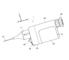
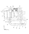
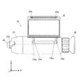
本実施形態の内視鏡装置1は、図1から図5に示すように挿入部10と、把持部本体20と、接眼部30と、操作スイッチ40と、蓋ロック部材50とを備えて構成されている。把持部本体20には電池装填部21が設けられている。
挿入部10は、体腔内に挿入される部分で、光ファイバーを内装した長尺で可撓性の本体を有し、基端部に設けられた着脱コネクタ11を介して把持部本体20に接続される。
挿入部10の先端から得られた像が接眼部30で観察可能に構成されている。本実施形態の内視鏡装置1は、挿入部10に光ファイバーを利用した細径の内視鏡に係るが、内視鏡の体内像を取得し出力するための技術要素は特に限定されるものではない。
なお、図中に直交3軸X−Y−Zを示す。X方向は、着脱コネクタ11の接続部から接眼部30へ向かう方向で、把持部本体20の長手方向に一致するとともに、把持部本体20に接続された挿入部10の基端における光軸方向に一致する。把持部本体20の幅方向がY方向、厚み方向がZ方向である。
As shown in FIGS. 1 to 5, the
The
An image obtained from the distal end of the
In the drawing, three orthogonal axes XYZ are shown. The X direction is a direction from the connection portion of the
本実施形態に係る把持部本体20は、角部に丸みを帯びた箱状の形態を有する。把持部の形態は限定されるものではなく、挿入部の基端に対して一体的に設けられ、把持部の位置、方向を操作することで、挿入部の基端の位置、方向を操作することができる部分であれば足りる。
The gripping part
把持部本体20に設けられた電池装填部21の電池を出し入れする開口部は、電池蓋22によって蓋われる。本実施形態ではヒンジ式の電池蓋22を開けることで電池装填部21に対する電池の出し入れが可能となる。適用される電池は、一次電池、二次電池等の種類を問わない。
An opening for taking in and out the battery of the
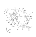
図2に示すように、電池蓋22の側端面にロック穴22aが設けられている。電池蓋22のヒンジ軸がX方向であり、ロック穴22aが設けられる電池蓋22の側端面がYZ面に平行な面である。ロック穴22aの深さ方向がX方向となる。
As shown in FIG. 2, a
一方、蓋ロック部材50は、X方向にスライド自在にして把持部筐体23に保持されている。蓋ロック部材50をX軸の正の方向にスライドさせると、蓋ロック部材50のロック端部51は把持部筐体23から電池装填部21の開口部に突出し、電池蓋22が閉じられた状態におけるロック穴22aに嵌入される。
On the other hand, the
蓋ロック部材50のX軸の負の方向の端部は操作端部52となっており、把持部筐体23から露出するとともにY軸の正の方向に曲げ形成され操作スイッチ40の外周部に臨んでいる。
操作端部52を指などで触れて直接操作することができる。操作端部52を押すことによりX軸の正の方向にスライドさせることができ、操作端部52を引くことによりX軸の負の方向にスライドさせることができる。操作端部52をX軸の負の方向に引き易くするために、操作端部52は把持部本体20のY軸の負の方向の端面においても一部露出している。
The end of the
The
操作スイッチ40及び着脱コネクタ11は、把持部本体20のX軸の負の方向の端面に配置されている。操作スイッチ40が、把持部本体20に接続された着脱コネクタ11と、蓋ロック部材50の操作端部52との間に挟まれ、これら3者がY方向に並んだ配置である。
操作スイッチ40は、X軸に平行な自身の中心軸回りに回動する方式のスイッチ部材である。
操作スイッチ40のX軸の負の方向の端部には、つまみ41が形成されている。操作スイッチ40の外周部には、蓋ロック部材50に対する押え部42a及び開放部42bと、着脱コネクタ11に対する押え部43a及び開放部43bがそれぞれ異なる角度範囲に形成されている。
The
The
A
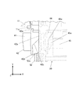
図3に示すように操作端部52の先端部52aが押え部42a及び開放部42bに対してX方向に重なる範囲まで及んでいる。開放部42bは、押え部42aに対してX軸の負の方向に凹んだ形状に形成されており、把持部本体20との間に蓋ロック部材50をスライド可能にするための隙間を保持する。
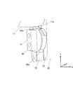
操作スイッチ40の操作角度に従って押え部42aがこの先端部52aに重なるとき、蓋ロック部材50は、ロック端部51を突出させた状態で押え部42aによって押えられ動作不能に保持される(図4、図5参照)。操作スイッチ40の操作角度に従って開放部42bがこの先端部52aに重なるとき、蓋ロック部材50はスライド可能にされるとともに、必要以上にスライドしたり、外れ落ちたりしないように開放部42bによって規制される(図1,2,3参照)。
開放部42bと押え部42aとの間には傾斜部42cが形成されている。傾斜部42cは、操作スイッチ40の回動により、先端部52aに重なる部分が開放部42bから押え部42aに変遷する過程において、蓋ロック部材50の操作端部52が突出していればこれを押し込む。
As shown in FIG. 3, the
When the
An
着脱コネクタ11の操作スイッチ40に対向する部分には、係合突起11aが形成されている。
着脱コネクタ11が把持部本体20に接続された状態で、操作スイッチ40の回動により押え部43aが係合突起11aを押えることにより、着脱コネクタ11を把持部本体20から離脱阻止するようにロックする(図4、図5参照)。そのため、係合突起11aがY軸の負の方向に突出しており、押え部43aが操作スイッチ40の径方向に突出しており、押え部43aの下面(X軸の正の方向の端面)が、着脱コネクタ11が把持部本体20に接続された状態における係合突起11aの上面(X軸の負の方向の端面)とX軸についてほぼ一致する位置である。X方向に見て押え部43aと係合突起11aとが一部重なり、押え部43aが係合突起11aの離脱方向側に接して係合突起11aを押えることで着脱コネクタ11を離脱阻止するようにロックする。
開放部43bは、以上の押え部43aのような係合突起11aに干渉する部分が無く、操作スイッチ40の回動により開放部43bが係合突起11aに対向する位置に配置されたときには、着脱コネクタ11の着脱が自由である。
An
In a state where the
The
図3及び図5に示すように、操作スイッチ40の回動によるON・OFF操作は、操作スイッチ40に連結された底部カム44を介して電気スイッチ部品45を操作することによって行われる。
電気スイッチ部品45は、スイッチ可動部45aが突出するようにバネにより支持された押下式のものであり、押下時にON(導通)、開放時(突出時)にOFF(非導通)となる。
電気スイッチ部品45は、X軸の正の方向にスイッチ可動部45aが押下されることでONとなるように配置されている。底部カム44はX軸に対して傾斜した底面44aを有する。底部カム44の回転中心から離れた位置でスイッチ可動部45aが底面44aに当接しており、底部カム44が操作スイッチ40と一体に回動することで、スイッチ可動部45aを押下若しくは開放して電気スイッチ部品45をON・OFF操作する。
なお、底部カム44及び押下式の電気スイッチ部品45に代えて、ロータリー式の電気スイッチ部品を適用し、その回転可動部を操作スイッチ40に連結して実施しても良い。
As shown in FIGS. 3 and 5, the ON / OFF operation by turning the
The
The
Note that, instead of the
電気スイッチ部品45は、電池装填部21に装填された電池を電源とした内視鏡電気駆動部のON・OFFを操作するスイッチとして電気回路に組み込まれている。
内視鏡電気駆動部としては、照明装置の光源素子や(設けられる場合は撮像素子、表示素子)その駆動回路が該当する。ここで、照明装置は体腔内を撮像するためのものであり、その光源素子としては挿入部10の先端部から照射する照明光の光源となるLED等の発光素子が該当する。
挿入部10により得られた体腔内の像を、接眼部30に光学系のみによって導く場合には、撮像素子や表示素子は設けられない場合もある。挿入部10により得られた体腔内の像を撮像素子(例えばCCD)で撮像してこの撮像した像を表示素子(例えばTFT液晶)に表示出力させて観察できるようにしてもよい。その場合、表示素子の表示画面を把持部の外装に設置して観察できるようにしてもよいし、表示素子の出力画像が接眼部30を介して観察できるようにしてもよい。接眼部30と、外装に設置した表示画面の双方を採用してもよい。
照明装置が設けられない場合としては、赤外線カメラを適用する場合が挙げられる。
The
The endoscope electric drive unit corresponds to a light source element of an illuminating device or a drive circuit thereof (an imaging element or a display element if provided). Here, the illumination device is for imaging the inside of a body cavity, and the light source element corresponds to a light emitting element such as an LED that serves as a light source of illumination light emitted from the distal end portion of the
When the image in the body cavity obtained by the
As a case where the illumination device is not provided, there is a case where an infrared camera is applied.
次に、本実施形態の内視鏡装置の使用手順につき説明する。
電池装填部21に電池を装填し、電池蓋22を閉める。
一方、着脱コネクタ11を把持部本体20に接続する。
次に、押え部42aが蓋ロック部材50を押え、押え部43aが係合突起11aを押えるように操作スイッチ40をつまんで回動させる。ことのき、電気スイッチ部品45はONとされ、本内視鏡装置は、体腔内を観察することできるように稼動する。また、蓋ロック部材50は、スライドしてロック穴22aに嵌入する。
Next, a procedure for using the endoscope apparatus of the present embodiment will be described.
A battery is loaded into the
On the other hand, the
Next, the
その後、操作スイッチ40を反対方向に回して、蓋ロック部材50に対して開放部42bが配置され、係合突起11aに対して開放部43bが配置され、電気スイッチ部品45がOFFとされた状態とすることができ、これにより、着脱コネクタ11を外したり、蓋ロック部材50を指等でスライドさせることでロック端部51をロック穴22aから離脱させて電池蓋22を開けたりすることができる。操作スイッチ40を回しただけでは、ロック端部51はロック穴22aから抜けていないから電池蓋22のロックは維持され、着脱コネクタ11の着脱作業時等に不意に電池蓋22が開放されることを防止でき、挿入部10の交換が必要で電池の交換が不要である時にも対応できる。特に挿入部10を単回使用品とした場合には、電池の1交換サイクル中に頻繁に挿入部10が交換される使用状況が予測される。
Thereafter, the
以上説明したように本実施形態にあっては、操作スイッチ40、蓋ロック部材50、ロック穴22a、係合突起11aなどにより、電池装填部21の電池蓋22を開放阻止するようにロックする機能、及び挿入部10の着脱コネクタ11を把持部から離脱阻止するようにロックする機能を有したロック機構が設けられている。電池蓋22をロックする機能と、着脱コネクタ11をロックする機能とは、いずれか一方のみを実施してもよい。
また以上説明したように本ロック機構は、操作スイッチ40の動作によりロック操作されるものであり、少なくとも操作スイッチ40により内視鏡電気駆動部のONが選択されている状態ではロック状態とされる。すなわち、内視鏡電気駆動部のONが選択される範囲では必ずロック状態にある。体腔内の観察時にロック状態を確保するためである。ロック解除状態は、内視鏡電気駆動部のOFFが選択される範囲の全部又は一部に設ける。操作スイッチの動作過程において、ロック状態とロック解除状態との切り替わり位置は、ONとOFFの切り替わり位置と一致している必要は無い。
As described above, in the present embodiment, the function of locking the
Further, as described above, the lock mechanism is locked by the operation of the
以上の実施形態の内視鏡装置によれば、体腔内に挿入される挿入部10の基端に把持部(本体20)が設けられてなり、電池の装填部21及び当該電池を電源とした照明等の内視鏡電気駆動部のON・OFFを操作する操作スイッチ40が把持部に設けられた内視鏡装置において、当該操作スイッチ40の動作によりロック操作される電池蓋22及び挿入部10の着脱コネクタ11のロック機構が設けられるから、ロック機構の操作部材を別途設ける必要がなく把持部の構成が簡素化され安価に構成可能となり、共通の操作スイッチにより内視鏡電気駆動部のON・OFF操作とロック機構のロック操作を行うことができ、操作性も簡素化する。
さらに、照明等の内視鏡電気駆動部のONが選択されている状態ではロック状態とされるから、照明等の内視鏡電気駆動部をONにして体腔内を観察している時に電池蓋22の開放及び挿入部10の着脱コネクタ11の離脱を阻止でき、安全性が向上する。
According to the endoscope apparatus of the above embodiment, the grip part (main body 20) is provided at the proximal end of the
In addition, when the ON state of the endoscope electric drive unit such as illumination is selected, the lock state is set. Therefore, when the endoscopic electric drive unit such as illumination is turned ON and the inside of the body cavity is observed, the
以上の実施形態では、内視鏡電気駆動部のONが選択されている状態でロック状態とされる段階と、内視鏡電気駆動部のOFFが選択されている状態でロック解除状態とされる段階とからなる2段階が実現され、操作スイッチ40によって相互に切替可能である。
さらに以下のように、3段階を実現してもよい。
すなわち、内視鏡電気駆動部のONが選択されている状態でロック状態とされる第1段階と、内視鏡電気駆動部のOFFが選択されている状態でロック状態とされる第2段階と、内視鏡電気駆動部のOFFが選択されている状態でロック解除状態とされる第3段階とを、操作スイッチにより選択可能に構成されたものである。その一例につき図6を参照して説明する。
In the above embodiment, the locked state is set when the endoscope electric drive unit is ON, and the unlocked state is set when the endoscope electric drive unit is OFF. Two stages consisting of stages are realized and can be switched to each other by the
Further, three steps may be realized as follows.
That is, the first stage that is locked when the endoscope electric drive unit is ON is selected, and the second stage that is locked when the endoscope electric drive unit is OFF. And the third stage that is unlocked in a state in which the endoscope electric drive unit is OFF is selected by an operation switch. One example will be described with reference to FIG.
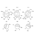
図6(a1)(b1)(c1)に示す操作スイッチ140は、上述の操作スイッチ40と同様に中心軸回りに回動する方式のスイッチ部材であるが、着脱コネクタ11に設けられる係合突起11aを押える押え部143aの周方向長さが比較的長くされたものである。押え部143aが係合突起11aに重なる状態で、着脱コネクタがロック状態となる。図6(b1)(c1)に示すように、操作スイッチ140の一定の回動角においてロック状態を維持できる。図6(a1)では、ロック解除状態である。
図6(a2)(b2)(c2)に示す底部カム144は、上述の底部カム44と同様の原理でスイッチ可動部45aを押下するものであり、これにより内視鏡電気駆動部のON・OFFが操作される。ON範囲をN、OFF範囲をFで示した。
The
The
図6(a1)(b1)(c1)に示す操作スイッチ140の角度状態は、順に図6(a2)(b2)(c2)に示す底部カム144の角度状態に対応している。
図6(a1) (a2)に示す角度では、押え部143aが係合突起11aから外れているのでロック解除状態であるとともに、スイッチ可動部45aがOFF範囲FにあるのでOFFであり、上掲の第3段階が実現される。なお、併せて実施する場合は、開放部42bが先端部52a上に配置される。
図6(b1) (b2)に示す角度では、押え部143aが係合突起11aに重なっているのでロック状態であるとともに、スイッチ可動部45aがOFF範囲FにあるのでOFFであり、上掲の第2段階が実現される。なお、併せて実施する場合は、押え部42aが先端部52a上に配置される。
図6(c1) (c2)に示す角度では、押え部143aが係合突起11aに重なっているのでロック状態であるとともに、スイッチ可動部45aがON範囲NにあるのでONであり、上掲の第1段階が実現される。なお、併せて実施する場合は、押え部42aが先端部52a上に配置される。
The angle state of the
At the angles shown in FIGS. 6 (a1) and (a2), since the
At the angles shown in FIGS. 6 (b1) and (b2), the
At the angle shown in FIGS. 6 (c1) and (c2), since the
図6(a1) (a2)に示す角度から操作スイッチ140を時計回りに回すことで、第3段階(ロック解除・OFF)→第2段階(ロック・OFF)→第1段階(ロック・ON)と切り替えることができ、図6(c1) (c2)に示す角度から操作スイッチ140を反時計回りに回すことで、第1段階(ロック・ON)→第2段階(ロック・OFF)→第3段階(ロック解除・OFF)と切り替えることができる。なお、時計回り方向をONとするか反時計回り方向をONとするかは任意である。
By turning the
したがって、本内視鏡装置を用いて観察を開始する前の準備段階で、図6(b1) (b2)に示す第2段階(ロック・OFF)に操作スイッチ140を操作し、電池蓋の開放や着脱コネクタの離脱を防ぐことができるとともに節電することができる。
また、一旦ONにした後に一時的にOFFにしたい場合や一時的にOFFにできる状況においても、図6(b1) (b2)に示す第2段階(ロック・OFF)に操作スイッチ140を操作し、電池蓋の開放や着脱コネクタの離脱を防ぐことができるとともに節電することができる。
第1段階(ロック・ON)、第2段階(ロック・OFF)及び第3段階(ロック解除・OFF)の並び順は、これらの各段階を選択可能にするという観点では任意であるが、以上説明したことにより第2段階を第1段階と第3段階の間に配置すること好ましい。すなわち、第2段階(ロック・OFF)を経ることなしに第1段階(ロック・ON)と第3段階(ロック解除・OFF)との相互の切替ができない機構を実施することが好ましい。
Therefore, in the preparatory stage before starting observation using the endoscope apparatus, the
Also, if you want to temporarily turn off after turning it on once, or in a situation where it can be turned off temporarily, the
The arrangement order of the first stage (lock / ON), the second stage (lock / OFF), and the third stage (unlock / OFF) is arbitrary from the viewpoint of making each of these stages selectable. As explained, it is preferable to arrange the second stage between the first stage and the third stage. That is, it is preferable to implement a mechanism that cannot switch between the first stage (lock / ON) and the third stage (unlock / OFF) without going through the second stage (lock / OFF).
以上の実施形態では、ロック機構は、操作スイッチ40からロック対象の電池蓋22又は着脱コネクタ11までの範囲に亘って機械的機構により構成された。電池蓋22に関しては、操作スイッチ40と電池蓋22との間において第3の部材である蓋ロック部材50が機械的に連携する。着脱コネクタ11に関しては、操作スイッチ40と着脱コネクタ11との間に第3の部材は関与しない。
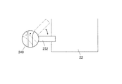
例えば、図7に示すように電池蓋22に関しても、第3の部材を介さず直接的に操作スイッチ40によって電池蓋22をロックするロック機構を実施することも可能である。
図7に示すロック機構にあっては、操作スイッチ240の一部として径方向に延設された蓋ロック部材252が、操作スイッチ240の回動操作に伴い回動して電池蓋22に干渉してロックする。
以上のように、操作スイッチからロック対象の電池蓋又は着脱コネクタまでの間に第3の部材を介さないロック機構や、第3の部材として様々な機械要素(例えば歯車、ラック、ベルト、プーリー、カム、スライダー、ネジ、リンクなど)によって操作力を伝動してロックするロック機構を実施することもできる。前者であれば、部品点数が少なく簡素で省スペースに構成できる。後者であれば、操作スイッチとロック対象との配置の自由度が増すとともに、操作力の増幅伝達により操作性を向上しやすい。
In the above embodiment, the lock mechanism is configured by a mechanical mechanism over a range from the
For example, as shown in FIG. 7, it is also possible to implement a lock mechanism that directly locks the
In the lock mechanism shown in FIG. 7, the
As described above, a lock mechanism that does not include the third member between the operation switch and the battery lid to be locked or the detachable connector, and various mechanical elements (for example, gears, racks, belts, pulleys, It is also possible to implement a locking mechanism that locks the operating force transmitted by a cam, slider, screw, link, etc.). In the former case, the number of parts is small, and the configuration can be simple and save space. In the latter case, the degree of freedom of arrangement of the operation switch and the lock target is increased, and the operability is easily improved by amplification transmission of the operation force.
図1から図5に示した実施形態は、スライダーとしての蓋ロック部材50がカムとしての操作スイッチ40によってロックする方向(X軸の正の方向)に押し込まれる動作を実現する一構成例である。
他の構成例を図8に示す。図8に示すのは、電池蓋22に設けた係合突起22bを蓋ロック部材150の係合溝150aで保持することでロックする機構である。操作スイッチ40によってロックする方向(X軸の正の方向)に押し込まれるスライダーとしての蓋ロック部材150に係合溝150aを形成し、電池蓋22に係合突起22bを形成する。係合溝150aは、係合突起22bが侵入する側の端面(Z軸の正の方向側の端面)から切り込まれ、ロック時スライド方向の逆方向(X軸の負の方向)に延設されている。必要により係合溝150aに連続する溝23aを把持部筐体23に形成する。電池蓋22を閉める過程で係合突起22bが係合溝150aに侵入し、操作スイッチ40を回動させて蓋ロック部材150をX軸の正の方向に押し込むことで、係合突起22bを係合溝150aで捕えて電池蓋22をロックすることができる。
The embodiment shown in FIG. 1 to FIG. 5 is an example of a configuration that realizes an operation in which a
Another configuration example is shown in FIG. FIG. 8 shows a mechanism that locks the
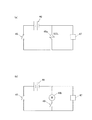
また、以上の実施形態に拘わらず、操作スイッチにより動作する電気アクチュエーターを含み、当該電気アクチュエーターの動力によりロック対象の電池蓋又は着脱コネクタをロックするロック機構を実施することも有効である。これを実施するための基本的な回路例を図9示した。
例えば図9(a)に示すように、電気スイッチ部品45によって電池46の電圧が内視鏡電気駆動部47に印加されると同時にソレノイド48aに印加される。ソレノイド48aが電池46の電圧印加時に動作して電池蓋又は着脱コネクタをロックする機械部分を動かしロックする構成とすることで実施することができる。
また、図9(b)に示すように、ソレノイドに代え電動モーター48bが電池46の電圧印加時に動作して電池蓋又は着脱コネクタをロックする機械部分を動かしロックする構成とすることで実施することができる。なお、このロック機能を無効化するためのスイッチ49を設けることもできる。
Regardless of the above-described embodiment, it is also effective to implement a lock mechanism that includes an electric actuator that is operated by an operation switch and that locks a battery cover or a detachable connector to be locked by the power of the electric actuator. A basic circuit example for implementing this is shown in FIG.
For example, as shown in FIG. 9A, the voltage of the
Further, as shown in FIG. 9 (b), the
なお、挿入部の着脱コネクタのロック機能を実施しない場合においては、挿入部に着脱コネクタを設けなくてもよいことは勿論である。 In addition, when not implementing the locking function of the attachment / detachment connector of an insertion part, of course, it is not necessary to provide an attachment / detachment connector in an insertion part.
1 内視鏡装置
10 挿入部
11 着脱コネクタ
11a 係合突起
20 把持部本体
21 電池装填部
22 電池蓋
22a ロック穴
22b 係合突起
23 把持部筐体
30 接眼部
40 操作スイッチ
42a 押え部
42b 開放部
42c 傾斜部
43a 押え部
43b 開放部
44 底部カム
44a 底面
45 電気スイッチ部品
45a スイッチ可動部
46 電池
47 内視鏡電気駆動部
48a ソレノイド
48b 電動モーター
50 蓋ロック部材
51 ロック端部
52 操作端部
52a 先端部
140 操作スイッチ
143a 押え部
144 底部カム
150 蓋ロック部材
150a 係合溝
240 操作スイッチ
252 蓋ロック部材
F OFF範囲
N ON範囲
DESCRIPTION OF
Claims (6)
前記装填部の電池蓋を開放阻止するようにロックする機能、及び/又は前記挿入部の着脱コネクタを前記把持部から離脱阻止するようにロックする機能を有したロック機構が設けられ、
前記ロック機構は、前記操作スイッチの動作によりロック操作され、少なくとも前記ONが選択されている状態でロック状態とされるように構成されたことを特徴とする内視鏡装置。 A gripping portion is provided at the proximal end of the insertion portion to be inserted into the body cavity, and an operation switch for operating ON / OFF of a battery loading portion and an endoscope electric drive portion using the battery as a power source is In the endoscope apparatus provided in the grip part,
A locking mechanism having a function of locking to prevent the battery cover of the loading unit from being opened and / or a function of locking to prevent the detachable connector of the insertion unit from being detached from the gripping unit;
The endoscope apparatus, wherein the lock mechanism is configured to be locked by an operation of the operation switch and to be locked when at least the ON is selected.
Priority Applications (1)
| Application Number | Priority Date | Filing Date | Title |
|---|---|---|---|
| JP2013212027A JP2015073739A (en) | 2013-10-09 | 2013-10-09 | Endoscope device |
Applications Claiming Priority (1)
| Application Number | Priority Date | Filing Date | Title |
|---|---|---|---|
| JP2013212027A JP2015073739A (en) | 2013-10-09 | 2013-10-09 | Endoscope device |
Publications (1)
| Publication Number | Publication Date |
|---|---|
| JP2015073739A true JP2015073739A (en) | 2015-04-20 |
Family
ID=52999066
Family Applications (1)
| Application Number | Title | Priority Date | Filing Date |
|---|---|---|---|
| JP2013212027A Pending JP2015073739A (en) | 2013-10-09 | 2013-10-09 | Endoscope device |
Country Status (1)
| Country | Link |
|---|---|
| JP (1) | JP2015073739A (en) |
Cited By (1)
| Publication number | Priority date | Publication date | Assignee | Title |
|---|---|---|---|---|
| CN121196438A (en) * | 2025-11-26 | 2025-12-26 | 湖南省华芯医疗器械有限公司 | A self-locking structure, an operating handle, and an endoscope |
-
2013
- 2013-10-09 JP JP2013212027A patent/JP2015073739A/en active Pending
Cited By (1)
| Publication number | Priority date | Publication date | Assignee | Title |
|---|---|---|---|---|
| CN121196438A (en) * | 2025-11-26 | 2025-12-26 | 湖南省华芯医疗器械有限公司 | A self-locking structure, an operating handle, and an endoscope |
Similar Documents
| Publication | Publication Date | Title |
|---|---|---|
| US8033993B2 (en) | Endoscope device and display device | |
| CN107809941B (en) | endoscope | |
| US7001329B2 (en) | Capsule endoscope guidance system, capsule endoscope holder, and capsule endoscope | |
| JP4365860B2 (en) | Endoscope device | |
| JP6368888B1 (en) | Endoscope tip cover | |
| JP4133074B2 (en) | Capsule endoscope holding mechanism | |
| US20080262293A1 (en) | Endoscopic operation assisting device | |
| EP2119391A2 (en) | Medical operation device | |
| CN112472001B (en) | Detachable endoscope | |
| US20230389785A1 (en) | Endoscope | |
| KR101754026B1 (en) | Biopsy forceps for endoscope | |
| US8613699B2 (en) | Device for the sterile sheathing of a sterilization-sensitive operating part | |
| US20240277214A1 (en) | Wireless camera assembly | |
| JP2015073739A (en) | Endoscope device | |
| JPWO2019087509A1 (en) | Medical device | |
| WO2019225089A1 (en) | External mechanism for endoscope | |
| JP5258357B2 (en) | Endoscope light source device | |
| CN109640782A (en) | The examination visual field ensures formula video-endoscope | |
| CN114245720A (en) | Endoscope with a detachable handle | |
| US11918188B2 (en) | Endoscope | |
| WO2019225108A1 (en) | External mechanism for endoscope | |
| US11647894B2 (en) | Processor for endoscope and endoscopic system | |
| JP2005192931A (en) | Endoscope device | |
| JP2022180048A (en) | Tip cap removal jig and endoscope | |
| JP2005192738A (en) | Endoscope device |