JP2015073726A - Hair dryer - Google Patents
Hair dryer Download PDFInfo
- Publication number
- JP2015073726A JP2015073726A JP2013211744A JP2013211744A JP2015073726A JP 2015073726 A JP2015073726 A JP 2015073726A JP 2013211744 A JP2013211744 A JP 2013211744A JP 2013211744 A JP2013211744 A JP 2013211744A JP 2015073726 A JP2015073726 A JP 2015073726A
- Authority
- JP
- Japan
- Prior art keywords
- moderation
- hair dryer
- handle
- engagement
- main body
- Prior art date
- Legal status (The legal status is an assumption and is not a legal conclusion. Google has not performed a legal analysis and makes no representation as to the accuracy of the status listed.)
- Granted
Links
Images


Landscapes
- Cleaning And Drying Hair (AREA)
Abstract
Description
本発明は、送風により頭髪等の対象物を乾燥させるヘアードライヤに関するものである。 The present invention relates to a hair dryer that dries an object such as hair by blowing air.
ヘアードライヤは、前方に空気(熱風)を吹き出す吹出し口を備えた本体ケースと、前記本体ケースに設けられたハンドル連結部に回転可能に取り付けられたハンドルを備えている。前記ヘアードライヤは、前記ハンドルを回転させ前記本体ケースに接近させた位置が、収納性や可搬性を高めた収納位置である。また、前記ヘアードライヤは、前記ハンドルを回転させ前記本体ケースから開いた位置が、使用者がハンドルを把持しやすくするための使用位置である。 The hair dryer includes a main body case having a blow-out port for blowing air (hot air) forward, and a handle rotatably attached to a handle connecting portion provided in the main body case. In the hair dryer, the position where the handle is rotated and brought close to the main body case is the storage position where the storage property and the portability are improved. In the hair dryer, a position where the handle is rotated and opened from the main body case is a use position for making it easier for the user to grip the handle.
前記ヘアードライヤは、前記ハンドルを収納位置又は使用位置のそれぞれの状態で回動規制するための節度構造を有している。前記節度構造は、前記ハンドル連結部の凹部に挿入され、弾性変形可能な節度リングと、前記節度リングの外周面に設けられた第1係合体と、凹部の内周面に設けられた第2係合体とを備えている。そして、前記節度構造は前記ハンドルが収納位置又は使用位置にあるとき、第1係合体と第2係合体とが係合し、前記ハンドルが反対側に移動しないように、ハンドルの回動を規制している。 The hair dryer has a moderation structure for restricting the rotation of the handle in the storage position or the use position. The moderation structure includes a moderation ring that is inserted into the concave portion of the handle connecting portion and can be elastically deformed, a first engagement body provided on the outer peripheral surface of the moderation ring, and a second engagement surface provided on the inner peripheral surface of the concave portion. And an engaging body. The moderation structure restricts the rotation of the handle so that the first engagement body and the second engagement body engage with each other and the handle does not move to the opposite side when the handle is in the storage position or the use position. doing.
そして、節度構造によって回動規制されているハンドルを使用者が反対側(ハンドルが収納位置にあるときは使用位置にあるいはその逆)に回動させるとき、前記第1係合体が前記第2係合体に押しのけられる。このとき、前記節度リングの前記第1係合体が形成されている部分の近傍が内側に向かって弾性変形し、この弾性変形によって前記第1係合体は前記第2係合体を乗り越える。そして、前記第2係合体を乗り越えたとき、前記節度リングは弾性的な復元力で元の形状に戻る。このようにして使用者は前記ハンドルを収納位置と使用位置との間で回動させることができる。 Then, when the user rotates the handle that is restricted by the moderation structure to the opposite side (when the handle is in the storage position, it is moved to the use position or vice versa), the first engagement body is moved to the second engagement. It is pushed away by coalescence. At this time, the vicinity of the portion where the first engagement body of the moderation ring is formed is elastically deformed inward, and the first engagement body gets over the second engagement body by the elastic deformation. When the second engagement body is overcome, the moderation ring returns to its original shape with an elastic restoring force. In this way, the user can rotate the handle between the storage position and the use position.
また、前記第1係合体が前記第2係合体に押しのけられるとき又は前記節度リングが弾性的に復元するとき、使用者は前記ハンドルより衝撃或いは振動(以下節度感)を感じる。この節度感を感じることで、使用者は前記ハンドルが収納位置又は使用位置に確実に移動したことを確認できるようになっている(特開2008−200153号公報等参照)。 Further, when the first engagement body is pushed away from the second engagement body or when the moderation ring is elastically restored, the user feels an impact or vibration (hereinafter referred to as moderation) from the handle. By feeling this moderation feeling, the user can confirm that the handle has moved to the storage position or the use position (see Japanese Patent Application Laid-Open No. 2008-200153).
しかしながら、特開2008−200153号公報に記載の発明では、第1係合体及び第2係合体とが前記ハンドルと同じ材料で形成されているため、前記ハンドルを収納位置と使用位置との間の移動を繰り返すと、第1係合体及び第2係合体が摩耗する。第1係合体及び第2係合体が摩耗すると、ハンドルを収納位置又は使用位置で確実に保持されなくなり、ヘアードライヤが使用しづらくなる。 However, in the invention described in Japanese Patent Application Laid-Open No. 2008-200353, since the first engagement body and the second engagement body are formed of the same material as the handle, the handle is disposed between the storage position and the use position. When the movement is repeated, the first engaging body and the second engaging body are worn. When the first engagement body and the second engagement body are worn, the handle is not reliably held in the storage position or the use position, and the hair dryer becomes difficult to use.
そこで本発明は、把持部が使用位置又は収納位置で確実に移動規制され、使用者の利便性を高めることができるヘアードライヤを提供することを目的とする。 Therefore, an object of the present invention is to provide a hair dryer in which the gripping portion is reliably restricted in movement at the use position or the storage position, and the convenience of the user can be improved.
また、本発明は、イオンを含む気流を頭髪に吹付け、短時間且つ確実に頭髪を乾燥させることで使用者の利便性を高めることができるヘアードライヤを提供することを目的とする。 Another object of the present invention is to provide a hair dryer that can enhance the convenience of the user by spraying an air stream containing ions on the hair and drying the hair for a short time and surely.
さらに本発明は、イオンを発生するイオン発生部の熱による不具合の発生を抑制し、使用者の利便性を高めることができるヘアードライヤを提供することを目的とする。 Furthermore, an object of the present invention is to provide a hair dryer that can suppress the occurrence of problems due to heat of an ion generation unit that generates ions, and can improve the convenience for the user.
上記目的を達成するため本発明は、内部に送風部と加熱部とを備えた本体ケースと、前記本体ケースに回動可能に取り付けられる把持部と、前記把持部の先端が前記本体ケースから最も離れた使用位置又は最も接近した収納位置にあるとき、前記把持部の回動を規制する節度部とを備え、前記節度部は前記本体ケース又は前記把持部の一方に設けられるとともに内側に向かって突出する第1係合部及び第2係合部を含む環状の内周面が形成された節度係合部と、前記本体ケース又は前記把持部の他方に固定される円環形状の係合体とを有しており、前記係合体は円環形状部と、前記円環形状部の径方向外側に突出するとともに径方向に弾性的に移動可能な凸部とを有しており、前記節度部は、前記把持部が前記使用位置にあるとき前記凸部が前記第1係合部と係合し、前記把持部が前記収納位置にあるとき前記凸部が前記第2係合部と係合することで把持部の回動を規制しており、前記第1係合部が、金属又はセラミックで形成されているとともに前記凸部と係合するように配置された節度ピンを有していることを特徴とするヘアードライヤを提供する。 In order to achieve the above object, the present invention provides a main body case having an air blowing section and a heating section therein, a gripping section that is rotatably attached to the main body case, and a tip end of the gripping section that is the most from the main body case. A moderation portion that restricts the rotation of the gripping portion when in a separated use position or the closest storage position, and the moderation portion is provided on one of the main body case or the gripping portion and faces inward. A moderation engagement portion formed with an annular inner circumferential surface including a first engagement portion and a second engagement portion projecting, and an annular engagement body fixed to the other of the main body case or the grip portion The engaging body has an annular shape portion and a convex portion protruding radially outward of the annular shape portion and elastically movable in the radial direction, and the moderation portion Is the convex portion when the grip portion is in the use position. The engaging portion is engaged with the first engaging portion, and the convex portion engages with the second engaging portion when the grasping portion is in the storage position, thereby restricting the rotation of the grasping portion. A hair dryer is characterized in that one engaging portion has a moderation pin formed of metal or ceramic and arranged to engage with the convex portion.
この構成によると、前記把持部が使用位置にあるとき、前記凸部と係合する前記第1係合部が金属又はセラミックで形成された節度ピンを用いており、前記凸部と前記節度ピンとが係合されるようになっている。このように構成されることで、前記第1係合部は前記把持部が回動するとき、前記凸部との摩擦による摩耗が発生しにくく、繰り返し使用した場合でも、前記凸部と前記第1係合部とがしっかり係合する。
According to this configuration, when the grip portion is in the use position, the first engaging portion that engages with the convex portion uses a moderation pin made of metal or ceramic, and the convex portion and the moderation pin Are to be engaged. By being configured in this manner, the first engaging portion is less likely to be worn by friction with the convex portion when the gripping portion rotates, and even when used repeatedly, the first engaging portion and the first engaging
これにより、前記把持部が使用位置にあるとき、前記把持部のがたつきが抑制されるため、使用者が把持部を持ちながら振った場合でも、前記本体ケースがぶれにくい。このことから、使用者の利便性を高めることが可能である。 Thereby, when the gripping portion is in the use position, rattling of the gripping portion is suppressed, so that even when the user shakes while holding the gripping portion, the main body case is unlikely to shake. From this, it is possible to improve the convenience of the user.
上記構成において、前記第2係合部の前記内周面から突出する突出量が、前記第1係合部の突出量よりも小さく形成されていてもよい。これにより、前記凸部と前記第2係合部との摩擦を低減することができ、前記凸部及び(又は)前記第2係合部の摩耗を低減することができる。 The said structure WHEREIN: The protrusion amount which protrudes from the said internal peripheral surface of a said 2nd engagement part may be formed smaller than the protrusion amount of a said 1st engagement part. Thereby, friction between the convex portion and the second engaging portion can be reduced, and wear of the convex portion and / or the second engaging portion can be reduced.
上記構成において、前記第2係合部は前記節度係合部と一体的に形成されていてもよい。これにより、節度ピンを取り付ける作業を、第1係合部のみでよく、作業性を高めることができる。 The said structure WHEREIN: The said 2nd engaging part may be formed integrally with the said moderation engaging part. Thereby, the operation | work which attaches a moderation pin needs only a 1st engaging part, and can improve workability | operativity.
上記構成において、前記第2係合部は前記第1係合部と同様の金属又はセラミックで形成された節度ピンを有していてもよい。これにより、前記凸部と前記第1係合部及び前記第2係合部との摩擦を低減し、前記凸部、前記第1係合部及び前記第2係合部の摩耗を低減することができる。 The said structure WHEREIN: The said 2nd engaging part may have the moderation pin formed with the metal or ceramic similar to the said 1st engaging part. Thereby, friction between the convex part and the first engaging part and the second engaging part is reduced, and wear of the convex part, the first engaging part and the second engaging part is reduced. Can do.
上記構成において、前記第2係合部は前記第1係合部と同様の金属又はセラミックで形成された節度ピンを有しており、前記第2係合部の節度ピンは、前記第1係合部の節度ピンよりも小型に形成されていてもよい。これにより、第1係合部と第2係合部の突出量を正確に調整することができる。 In the above configuration, the second engagement portion has a moderation pin made of the same metal or ceramic as the first engagement portion, and the moderation pin of the second engagement portion is the first engagement portion. You may form smaller than the moderation pin of a joint part. Thereby, the protrusion amount of a 1st engaging part and a 2nd engaging part can be adjusted correctly.
上記構成において、前記節度部は、前記把持部の回動の中心に対して点対称形状を有していてもよい。これにより、前記係合体に作用する力が相殺されるため、前記係合体が取り付けられる部材に作用する力を低減することができる。 The said structure WHEREIN: The said moderation part may have a point symmetrical shape with respect to the rotation center of the said holding part. Thereby, since the force which acts on the said engagement body is canceled, the force which acts on the member to which the said engagement body is attached can be reduced.
上記構成において、前記係合体は前記節度ピンに対し摺動性が高い材料で形成されている。これにより、前記凸部の摩耗を低減することが可能である。 The said structure WHEREIN: The said engagement body is formed with the material with high slidability with respect to the said moderation pin. Thereby, it is possible to reduce wear of the convex portion.
上記目的を達成するため本発明は、前記本体ケースが、内部に前記加熱部を配置するとともに内部を前記送風部からの気流が通過する先細りテーパー形状の断熱筒部と、前記断熱筒部の内部に配置され前記加熱部を保持するとともに、前記断熱筒部を周方向に分割する基板とを備えており、前記断熱筒部の気流の流れ方向下流側の端部は、一方向に前記テーパー形状の勾配よりも急な勾配の傾斜部を有する流速増速部と、前記傾斜部と連続するとともに、気流の流れ方向に沿って延びる平面部を有する整流部とを備えており、前記前記平面部の外面側にはイオン発生部が設けられており、前記イオン発生部のイオンを発生する電極が、前記断熱筒部の整流部に突出している。 In order to achieve the above object, the present invention provides a taper-shaped heat-insulating cylindrical part in which the main body case has the heating part disposed therein and an air flow from the air blowing part passes inside, and the inside of the heat-insulating cylindrical part. And a substrate that divides the heat insulating cylinder part in the circumferential direction, and an end of the heat insulating cylinder part on the downstream side in the flow direction of the airflow is tapered in one direction. A flow velocity accelerating portion having an inclined portion with a steeper slope than the gradient, and a rectifying portion having a flat portion that is continuous with the inclined portion and extends along the flow direction of the airflow, and the flat portion An ion generating part is provided on the outer surface side of the electrode, and an electrode for generating ions of the ion generating part protrudes from the rectifying part of the heat insulating cylinder part.
この構成によると、断熱筒部にイオン発生部を取り付けた構成となっているため、小型化、軽量化することが可能である。また、整流部で確実に整流した気流を吹き付けるため、気流が頭髪の内部に到達しやすく、それだけ、乾燥の効率を高めることができる。 According to this structure, since it has the structure which attached the ion generating part to the heat insulation cylinder part, it can be reduced in size and weight. Moreover, since the airflow reliably rectified by the rectifying unit is blown, the airflow easily reaches the inside of the hair, and the drying efficiency can be increased accordingly.
上記構成において、前記基板は十字状に組み立てられた第1板部と第2板部とを備えており、前記第1板部は前記平面部に沿うとともに、前記整流部全体を分割するように配置されており、前記第2板部は前記第1板部と交差するように設けられており、前記イオン発生部はプラス電極とマイナス電極とが前記第2板部を挟んで前記整流部に突出している。これにより、プラスに帯電したイオンとマイナスに帯電したイオンとが発生直後に結びつくのを抑制することができる。また、前記整流部が前記第1板部で前記平板部が形成されている側と反対側に分割されており、イオン発生部が配置されている側の流速が反対側に比べて速くなっている。イオン発生部で発生したイオンは流速が速い気流に乗ってヘアードライヤの外部に排出されるため、遠くまで(すなわち、毛髪の奥まで)届きやすい。 In the above configuration, the substrate includes a first plate portion and a second plate portion assembled in a cross shape, and the first plate portion extends along the planar portion and divides the entire rectifying portion. And the second plate portion is provided so as to intersect the first plate portion, and the ion generating portion includes a positive electrode and a negative electrode sandwiched between the second plate portion and the rectifying portion. It protrudes. Thereby, it is possible to suppress the positively charged ions and the negatively charged ions from being combined immediately after generation. Further, the rectifying unit is divided on the side opposite to the side where the flat plate part is formed in the first plate part, and the flow velocity on the side where the ion generating part is arranged becomes faster than the opposite side. Yes. Since the ions generated in the ion generating unit are discharged to the outside of the hair dryer on an air current having a high flow velocity, they are easy to reach far away (that is, to the back of the hair).
上記構成において、前記第2板部の前記整流部内に配置されている部分は、前記第1板部を挟んで平面部側の部分が、反対側の部分よりも前記気流の流れ方向の下流側に長く形成されている。これにより、整流部の整流を行う実質的な長さを、流速が速い部分を長く、流速が遅い部分を短くしている。また、流速が遅い部分では、整流が行われた気流を早めに混合することで、気流の温度むらを抑制している。 In the above configuration, the portion of the second plate portion disposed in the rectifying portion is such that the portion on the plane portion side with respect to the first plate portion is downstream of the opposite side portion in the airflow direction. It is formed long. Thereby, the substantial length which rectifies | straightens a rectification | straightening part is lengthened the part with a quick flow velocity, and shortened the part with a slow flow velocity. Further, in the portion where the flow velocity is slow, the air flow that has been rectified is mixed early to suppress the temperature unevenness of the air flow.
上記構成において、前記整流部の内部には、前記断熱筒部の他の部分よりも多くの領域に分割されるように基板が配置されている。これにより、より確実に整流を行うことが可能となる。なお、分割数としては4〜8程度が好ましく、基板の配置としては、放射状に配置するものを挙げることができる。 The said structure WHEREIN: The board | substrate is arrange | positioned so that it may be divided | segmented into the area | region more than the other part of the said heat insulation cylinder part inside the said rectification | straightening part. This makes it possible to perform rectification more reliably. Note that the number of divisions is preferably about 4 to 8, and the substrate may be arranged radially.
上記目的を達成するため本発明は、前記加熱部は等間隔に並んで形成された波形状を有する電線を、前記断熱筒部に沿うようにらせん状に巻き回した発熱部を備えており、前記発熱部は、前記らせん状の軸方向に見て、前記軸周りに対称形状となる対称部と、前記平面部と平行な面に対する鏡像と組み合わせたときの中心軸が前記らせん状の軸と重なる2つの異なる形状を前記らせん状の軸周りに対称とならないように組み合わせた非対称部とを備えており、前記非対称部は、前記らせん状の軸をとおり前記平面部と平行な面から突出する高さが、前記イオン発生部側に配置される部分が、反対側よりも低い。 In order to achieve the above object, the present invention comprises a heating part in which the heating part is wound in a spiral shape so as to follow the heat insulating cylinder part, and the electric wire having a wave shape formed in a line at equal intervals. The heat generating portion has a symmetrical portion that is symmetrical about the axis when viewed in the helical axial direction, and a central axis when combined with a mirror image with respect to a plane parallel to the flat portion is the helical axis. And an asymmetric part combining two different overlapping shapes so as not to be symmetric about the spiral axis, and the asymmetric part protrudes from a plane parallel to the plane part through the spiral axis. The height of the portion arranged on the ion generating part side is lower than that on the opposite side.
このように、加熱部の前記らせん状の軸方向に前記イオン発生部に近い部分を非対称部とすることで、加熱部とイオン発生部とを一定間隔あけて配置することができる。これにより、イオン発生部が前記加熱部の熱によって誤作動したり、破損したりするのを抑制することが可能である。また、前記加熱部の発熱部として、波形状を変更せずに巻き回す形状のみを変更しているため、波形状のピッチを変更する構成に比べて組み付けが容易である。また、対称形状を有したままで、軸をイオン発生部から離すようにずらす方法に比べて、断熱筒部が大型化するのを抑制することができ、ヘアードライヤ自体が大きくなるのを抑制することができる。これにより、大型化することなくイオンを安定的に放出することができるので、使用者の利便性を高めることが可能である。 Thus, the heating part and the ion generation part can be arranged at a predetermined interval by making the part close to the ion generation part in the spiral axial direction of the heating part an asymmetric part. Thereby, it is possible to suppress that the ion generation part malfunctions or is damaged by the heat of the heating part. Moreover, since only the shape which winds without changing a wave shape is changed as a heat-emitting part of the said heating part, an assembly | attachment is easy compared with the structure which changes the pitch of a wave shape. Moreover, compared with the method of shifting the axis away from the ion generating portion while maintaining the symmetrical shape, it is possible to suppress an increase in the size of the heat insulating cylindrical portion and to suppress an increase in the hair dryer itself. be able to. Thereby, since ion can be stably discharge | released without enlarging, it is possible to improve a user's convenience.
上記構成において、前記非対称部が、前記整流部の一部に形成されていてもよい。 The said structure WHEREIN: The said asymmetric part may be formed in a part of said rectification | straightening part.
本発明によると、使用回数にかかわらず、把持部が使用位置又は収納位置で確実に維持され、使用者の利便性を高めることができるヘアードライヤを提供することができる。 According to the present invention, it is possible to provide a hair dryer in which the gripping portion is reliably maintained at the use position or the storage position regardless of the number of times of use, and the convenience of the user can be improved.
以下に本発明の実施形態について図面を参照して説明する。 Embodiments of the present invention will be described below with reference to the drawings.
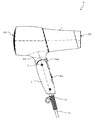
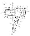
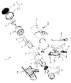
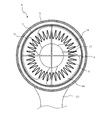
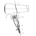
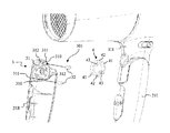
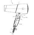
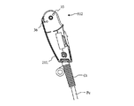
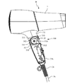
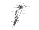
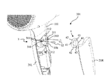
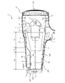
図1は本発明にかかるヘアードライヤの一例の側面図であり、図2は図1に示すヘアードライヤの断面図であり、図3は図1に示すヘアードライヤの分解斜視図であり、図4は図2に示すヘアードライヤをIV−IV線で切断した断面図である。図1に示すように本発明にかかるヘアードライヤAは、横長筒形状の本体ケース1と、本体ケース1の下部に形成されたハンドル取付部111にヒンジ部3を介して取り付けられたハンドル2(把持部)とを有している。そして、本体ケース1の後端部は空気を吸い込む吸込口101を構成しており、吸込口101には吸込みグリル12が設けられている。また、本体ケース1の前端部は空気を吐出する吐出口102を構成しており、吐出口102には吐出グリル13が設けられている。
1 is a side view of an example of a hair dryer according to the present invention, FIG. 2 is a sectional view of the hair dryer shown in FIG. 1, FIG. 3 is an exploded perspective view of the hair dryer shown in FIG. FIG. 4 is a cross-sectional view of the hair dryer shown in FIG. 2 cut along line IV-IV. As shown in FIG. 1, a hair dryer A according to the present invention includes a horizontally long
図3に示すように、吸込みグリル12は、吸込みメッシュ121と、吸込みメッシュ121を押えるための吸込みリング122とを有している。吸込みメッシュ121は、吸込口101から空気が吸い込まれるとき、本体ケース1の内部空間100に異物が吸い込まれるのを抑制するために設けられている。吐出グリル13は、吐出メッシュ131と、吐出メッシュ131を押えるための吐出リング132とを有している。吐出メッシュ131は、本体ケース1の内部の部材(例えば外れたねじ等)が空気の流れとともに吐出されるのをよくせいする。また、また、使用者が誤って手指等を挿入し、内部の機器に触れるのを抑制する役割も果たしている。
As shown in FIG. 3, the
図3に示すように、本体ケース1は、左ハウジング11Lと右ハウジング11Rとを有しており、左ハウジング11Lと右ハウジング11Rとを組み合わせる構成を有している。また、ハンドル2も本体ケース1と同様、左ハンドルカバー21Lと右ハンドルカバー21Rとを有している。左ハウジング11Lと右ハウジング11Rとを組み合わせたのち、ハンドル取付部111の左右両サイドから、それぞれ左ハンドルカバー21L及び右ハンドルカバー21Rを組み合わせる。そして、ねじ20を左右ハウジング11L及び11R、左右ハンドルカバー21L及び21Rを貫通させ、先端部を螺合することで、本体ケース1とハンドル2とが回動可能に連結される。これにより、ハンドル2はねじ20を中心に回動する。
As shown in FIG. 3, the
左右ハウジング11L及び11R、左右ハンドルカバー21L及び21Rは、ABS等の樹脂で形成されている。これにより、本体ケース1やハンドル2に熱が伝わりにくく、本体ケース1やハンドル2にふれても痛みを感じたり、火傷をしたりするのを抑制することができる。
The left and
また、ハンドル2の先端部には、電源供給のための電源ケーブルPcが設けられている。電源ケーブルPcは、左ハンドルカバー21Lと右ハンドルカバー21Rに挟まれることで保持される保持部Ctの内部を通過するように配置されている。
A power cable Pc for supplying power is provided at the tip of the
左ハウジング11Lと右ハウジング11Rを組み合わせることで、本体ケース1の上部に円柱状の内部空間100が形成される。そして、図2、図3に示すように、本体ケース1の内部の内部空間100には、ファン14(送風部)、モータ15、ヒータ5(加熱部)、ヒータ基板6(基板)、断熱スリーブ7(断熱筒部)及びイオン発生ユニット8(イオン発生部)が設けられている。ファン14は複数枚(ここでは、3枚)のプロペラを有する軸流送風機であり、内部空間100の最も吸込口101に近い部分に配置されている。ファン14は円筒状のファンケース141の内部に回転可能に配置されておりモータ15からの回転力によって回転する。ファン14が回転することで、本体ケース1の内部空間100に軸方向正面側に向かう空気の流れ(以下、気流と称する場合がある)が発生する。
By combining the
ファンケース141には、径方向に延びるとともに周方向に等間隔に並べられた複数個のフィンが設けられている。このフィンは、モータ15を支持するとともに、ファン14で発生した空気の流れ(旋回流)をファン14の回転方向に揃える役割を果たしている。
The
図3に示すように、モータ15は、ファンケース141にモータ用緩衝部材151を介して配置されている。モータ用緩衝部材151は、モータ15の駆動時の振動等を抑制するものである。
As shown in FIG. 3, the
本体ケース1の内部の内部空間100のモータ15の正面側には、ヒータ5が取り付けられるヒータ基板6が配置されている。図2、図3に示すように、ヒータ5が配置されたヒータ基板6が本体ケース1の内部の内部空間100に配置された筒状の断熱スリーブ7の内部に取り付け固定される。これにより、ヒータ5は断熱スリーブ7の内部に、断熱スリーブ7に接触しないように取り付けられる。
A
ヒータ5は内部空間100の軸方向に厚みを有する金属線(ニクロム線等)をヒータ基板6にらせん状に巻回した形状を有している。このような金属線に電流を流すことで、ジュール熱により発熱させ、近接している空気を加熱する。そして、図4に示すように、ヒータ5は周方向に周期的に配置された波型に形成されている。このように、波型に形成されていることで、通過する空気との接触面積を増やし、空気を効率よく加熱している。
The
断熱スリーブ7には、内面に密着するように取り付けられた断熱コーン71が取り付けられている。断熱スリーブ7は例えば樹脂で形成されており、断熱コーン71はマイカで形成されている。このような、断熱スリーブ7及び断熱コーン71が取り付けられていることで、ヒータ5の熱が外部に到達するのを抑制している。これにより、空気の加熱効率を高めるとともに、本体ケース1の外面が高温になるのを抑制し、使用者が触れても痛みを感じたり、火傷してしまったりするのを抑制している。なお、断熱スリーブ7のみで十分な断熱効果を得ることができる場合、断熱コーン71を省略することが可能である。また、断熱スリーブ7と断熱コーン71の間に隙間を形成するようにしてもよい。断熱スリーブ7と断熱コーン71の間の隙間が空気の層を形成し、断熱性をより高めることが可能となる。
A
断熱スリーブ7は正面側に行くにしたがって小径になるようなテーパー形状を有しており、本体ケース1の正面端部に到達している。断熱スリーブ7は、テーパー状に形成されており、内部を流れる気流の流速を高めている。断熱スリーブ7の背面側の端部はファンケース141が連結している。そして、ファンケース141の背面側には吸込みグリル12が取り付けられており、断熱スリーブ7の正面側の端部には吐出グリル13が取り付けられている。すなわち、吸込みグリル12、ファンケース141、断熱スリーブ7及び正面グリル13は、本体ケース1の軸方向に気密に連結されており、通風路16を形成している。
The
本体ケース1の正面側の端部近傍の上部には、イオン発生ユニット8が設けられている。イオン発生ユニット8は、本体80と、イオンを発生するプラス電極81と、マイナス電極82とを備えている。イオン発生ユニット8の本体80は、断熱スリーブ7の上部に配置されており、プラス電極81及びマイナス電極82が、断熱スリーブ7の内部に向かって突出している。イオン発生ユニット8を吐出口102の近くに配置することで、発生したイオンが本体ケース1の内部の部材に付着し、消滅してしまうのを抑制できる。これにより、ヘアードライヤAは、一定量のイオンを含む気流を安定して吐出することができる。
An
また、図2に示しているように、ハンドル2自体及び本体ケース1のハンドル2の近傍には、第1スイッチSw1、第2スイッチSw2及び第3スイッチSw3が備えられている。第1スイッチSw1は、スライドスイッチであり、ヘアードライヤAの入/切の切替えやモータ15の回転数を調整し、空気の流量を調整するスイッチである。第2スイッチSw2は押しボタンスイッチであり、スイッチを押したときに吐出口102から冷風が吐出されるようにするスイッチである。つまり、第2スイッチSw2はヒータ5の入/切を切り替えるスイッチである。第3スイッチSw3はイオンの発生を切り替えるスイッチである。第1スイッチSw1、第2スイッチSw2及び第3スイッチSw3をハンドル2又はハンドル2の近くに配置することで、使用者の利便性を高めることが可能である。なお、各スイッチによる動作は一例であり、これに限定されるものではない。
Further, as shown in FIG. 2, a first switch Sw <b> 1, a second switch Sw <b> 2, and a third switch Sw <b> 3 are provided in the vicinity of the
(第1実施形態)
次に、本発明にかかるヘアードライヤの要部であるヒンジ部3の詳細について図面を参照して説明する。図5は本発明にかかるヘアードライヤの右ハンドルカバーを取り外した状態を示す図であり、図6は本発明にかかるヘアードライヤの右ハンドルカバーを示す図であり、図7は本発明にかかるヘアードライヤの節度部の分解斜視図である。また、図8は本発明にかかるヘアードライヤのハンドルが使用位置にあるときの節度部を示す部分断面図であり、図9は本発明にかかるヘアードライヤのハンドルが収納位置にあるときの節度部を示す部分断面図である。また、図10は本発明にかかるヘアードライヤの左ハンドルカバーを取り外した状態を示す図であり、図11は本発明にかかるヘアードライヤの左ハンドルカバーを示す図である。
(First embodiment)
Next, the detail of the
ヘアードライヤAにおいて、ハンドル2はヒンジ部3を介して、本体ケース1に取り付けられている。ハンドル2は、使用者の操作によって、本体ケース1の気流の流れ方向と交差するように持ち上げた使用位置P1(図8参照)と、本体ケース1に沿う位置に収納した収納位置P2(図9参照)との間を回動する。ヒンジ部3は、ハンドル2の位置を使用者に節度感で知らせる節度部301(図5〜図9参照)と、ハンドル2が可動範囲を超えて回動されるのを抑制するための回動規制部302(図10、図11参照)とを備えている。
In the hair dryer A, the
まず節度部301について説明する。図5、図6に示すように節度部301は、ハンドル2を把持している使用者に対して、節度感、すなわち折り曲げ動作時にクリック感をか感じさせる構成であり、本体ケース1の右ハウジング11Rと右ハンドルカバー21Rとに設けられている。節度部301は、右ハンドルカバー21Rに一体的に形成された節度リブ31(節度係合部)、節度リブ31の内部に設けられる節度ピン32、本体ケース1の右ハウジング11Rに取り付けられるハンドルリング4(係合体)とを有している。
First, the
節度リブ31は、中央部分をねじ20が貫通するとともにハンドルリング4が回動可能に挿入される円筒状のリブである。節度リブ31は、円柱状の節度ピン32を保持するピン保持部310を備えている。図6に示すように、ピン保持部310は、内周部の一部に不連続部分を有するとともに外部に向かって張り出した形状を有している。ピン保持部310は不連続部分で節度リブ31と連結されている。ピン保持部310は節度ピン32の外周面の一部が、節度リブ31の内側に突出するように節度ピン32を保持している。
The
そして、節度部301では、節度ピン32の節度リブ31の内周面から内側に突出する部分を第1係合部311としている。なお、節度ピン32として、ここでは金属(ステンレス、アルミ合金、、真鍮等)で形成されているものとしているが、これに限定されない。例えば、セラミック等の耐摩耗性の高い材料を広く採用することができる。また、節度リブ31は、中心を挟んで対称となる位置にピン保持部310が設けられている。ピン保持部310は、ハンドル2が使用位置P1(図8参照)にあるとき、ハンドルリング4の後述する凸部41が係合し、ハンドル2の回動を制限する位置に形成されている。
In the
節度リブ31の内周面には、第1係合部311から周方向に一定間隔離れた位置に、内側に向かって突出した(傾斜した)第2係合部312が設けられている。第2係合部312も中心を挟んで対向する部分に2個設けられている。なお、第2係合部312は、節度リブ31と一体で形成されており、節度リブ31、すなわち、右ハンドルカバー21Rと同じ樹脂で形成されている。
On the inner peripheral surface of the
第2係合部312は、ハンドル2が収納位置P2(図9参照)にあるとき、ハンドルリング凸部41が係合し、ハンドル2の回動を制限する位置に形成されている。なお、第2係合部312の節度リブ31の内側に突出する突出量は、第1係合部311の突出量よりも少なく形成している。第1係合部311及び第2係合部312の詳細については、後述する。
The
図5、図8、図9に示すように、右ハウジング11Rのヒンジ部3を構成する部分にはハンドルリング4が取り付けられるリング取付部30が形成されている。リング取付部30は長円(楕円)形状を有しており、長手方向の両端部にハンドルリング4と係合するようになっている。
As shown in FIGS. 5, 8, and 9, a
ハンドルリング4は、円環形状を有する部材であり、ここでは、POM(ポリアセタール樹脂)で形成されている。なお、ハンドルリング4の構成材料としては、POMに限定されるものではなく節度ピン32との間で摺動性が高く弾性変形可能な材料(各種エンジニアリングプラスティック等)を広く採用することができる。ハンドルリング4は、2個の半円状の弾性変形部42をリング状に組み合わせた形状を有しており、弾性変形部42の境界部分の内周面には内側に突出する係合部43が設けられている。そして、弾性変形部42の中間部分には、外周面から外側に突出する凸部41が設けられている。
The
図6に示すように、ハンドルリング4は係合部43をリング取付部30の長手方向の端部に係合することで、右ハウジング11Rに取り付けられる。ハンドルリング4をリング取付部30に取り付けたとき、弾性変形部42とリング取付部30との間には隙間が形成される。この隙間は、凸部41が押されたとき、弾性変形部42が変形しつつ退避する部分となる。
As shown in FIG. 6, the
図7に示すように、右ハンドルカバー21Rの節度リブ31のピン保持部310に節度ピン32を取り付ける。また、右ハウジング11Rのリング取付部30にハンドルリング4を取り付ける。そして、ハンドルリング4の少なくとも一部が節度リブ31の内部に配置されるように、右ハウジング11Rに右ハンドルカバー21Rを取り付ける。このとき、節度リブ31とハンドルリング4とは中心軸が重なるように配置されており、右ハンドルカバー21R(ハンドル2)をヒンジ部3(ねじ20)周りに回動させると、節度リブ31がハンドルリング4の回りを回動する。
As shown in FIG. 7, the
ハンドル2が使用位置P1にあるときについて説明する。ハンドル2が本体ケース1の下部から下方に向かって延びる位置にあるとき、使用者がヘアードライヤAの操作が容易になる。そのため、ハンドル2を本体ケース1かに対して交差するように回動した位置を使用位置P1としている。また、ヘアードライヤAをコンパクトに収納するため、ハンドル2を本体ケース1に沿うように回動させた位置を収納位置P2としている。以下の説明では、使用位置P1及び収納位置P2と表示する場合、この位置と同じものとする。
A case where the
図8に示すように、ハンドル2が使用位置P1にあるとき、右ハンドルカバー21Rに設けられている節度リブ31の第1係合部311は、ハンドルリング4の凸部41と係合している。図8において、ハンドル2は、左回り(反時計回り)に回転することで使用位置P1から収納位置P2に回動する。節度リブ31は右ハンドルカバー21Rと同期して回転するため、節度リブ31も反時計回りに回転する。このとき、節度リブ31の第1係合部311は回動が規制されるように、ハンドルリング4の凸部41と係合される。これにより、ハンドル2は収納位置P2への回動が規制される。
As shown in FIG. 8, when the
ハンドル2を一定以上の力で回動させると、凸部41は曲面状に形成されているため、同じく曲面状に突出している第1係合部311に周方向に押されることで、その力は径方向内側に作用する。第1係合部311が凸部41を周方向に押す。凸部41は弾性変形部42の中央に設けられているため、凸部41が径方向に押されと、弾性変形部42が変形し、凸部41が径方向内側に移動する。これにより、第1係合部311が凸部41を通過することができるようになる。このことからも、ハンドル2は弾性変形部42の弾性力によって使用位置P1に保持されていることがわかる。
When the
第1係合部311が凸部41を周方向に乗り越えると、凸部41が第1係合部311から押されなくなるので、弾性変形部42が弾性力によりもとの形状に戻る。このとき、凸部41が節度リブ31に衝突し、ハンドル2を把持している使用者は節度感(クリック感)を感じる。この節度感によって、使用者はハンドル2が使用位置P1から収納位置P2側に回動している(使用位置P1からずれた)ことを認識できる。
When the first engaging
ハンドル2が収納位置P2側に回動されると、節度リブ31がハンドルリング4に対して回転する。これにより、第2係合部312がハンドルリング4の凸部41に接近する。図9に示すように、第2係合部312は、周方向に傾斜した形状を有しているため、凸部41が徐々に径方向に押される。これにより、弾性変形部42も徐々に変形し、第2係合部312の端部が凸部41を超えたとき、凸部41が第2係合部312から押されなくなるので、弾性変形部42が弾性力によりもと形状に戻る。このとき、凸部41が節度リブ31に衝突し、ハンドル2を把持している使用者に節度感を発し、使用者は節度感によってハンドル2の収納位置P2への回動が完了したことを認識する。第2係合部312が凸部41と係合することで、ハンドル2の収納位置P2から使用位置P1への回動が規制される。
When the
また、ハンドル2が収納位置P2から使用位置P1に移動するときは、上述の逆である。すなわち、第2係合部312が凸部41を乗り越える。そして、ハンドル2が使用位置P1に近づくと、凸部41が第1係合部311に押され、弾性変形部42がハンドルリング4の内側に向かって変形する。そして、第1係合部311が凸部41を乗り越えると、弾性変形部42が元の位置に戻るときに、凸部41が節度リブ31に接触し、節度感を出力する。
Further, when the
ハンドル2が使用位置P1にあるとき、使用者はハンドル2を把持して、ヘアードライヤAを使用するため、ヒンジ部3にかかる力が大きくなる。ハンドル2がぐらついたり、ずれたりするのを抑制するため、ハンドル2が使用位置P1にあるときハンドル2がしっかり回動規制されていることが好ましい。そのため、ハンドル2が使用位置P1にあるとき、凸部41と第1係合部311とがしっかり係合するようになっている。
When the
また、ハンドル2が収納位置P2にあるとき、使用者がハンドル2を把持してヘアードライヤAを使用することはほとんどない。そして、使用者はヘアードライヤAを使用する場合、必ずハンドル2を使用位置P1に移動させるものであるため、軽い力で回動できることが好ましい。そのため、ハンドル2は自重等で勝手に回動しない程度に回動規制がなされている。
Further, when the
これらのことより、ヘアードライヤAでは、凸部41としっかり係合する必要がある第1係合部311の突出量を、緩い係合でよい第2係合部312の突出量に比べて大きくなるように構成されている。また、突出量が異なることで、第1係合部311又は第2係合部312が凸部41を乗り越えるのに必要な力も異なる。そして、突出量が多い第1係合部311と凸部41とが係合しているときの方が、第2係合部312と係合しているときに比べて移動に要する力が大きくなる。このことから、ヘアードライヤAでは、ハンドル2が使用位置P1にあるとき、収納位置P2にあるときよりも強い力で回動規制している。ヘアードライヤAでは、使用時にハンドル2を持って操作するとき、ヒンジ部3に大きな力が作用するため、使用時にハンドル2が使用者の意に反して収納位置P2に回動するのを抑制できる。一方、第2係合部312の突出量を第1係合部311に比べて小さくすることで、収納位置P2にあるハンドル2を簡単に使用位置P1方向に回動させることが可能となる。
Therefore, in the hair dryer A, the protruding amount of the first engaging
さらに、第1係合部311又は第2係合部312が凸部41を乗り越えるとき、第1係合部311又は第2係合部312は凸部41に押し付けられている状態となっている。そして、この状態で、第1係合部311又は第2係合部312は凸部41に対して摺動するため、摩擦力が大きくなり、それぞれの部材の摩耗が大きくなる。
Further, when the first engaging
ハンドルリング4は、上述のとおり金属製の節度ピン32に対して摺動性が高いPOM等の樹脂で形成されている。そのため、節度ピン32と凸部41との摺動性が高く、凸部41は摩耗しにくい。一方、右ハンドルカバー21Rと同じ材料で形成されている第2係合部312はABS樹脂等の樹脂材料で形成されている。そして、ABS樹脂とPOMとの接触は金属ピンとの接触に比べて摩擦が大きい。そのため、第2係合部312の突出量を第1係合部311よりも小さくし、第2係合部312と凸部41との摩擦を低減することで、摩耗を抑制している。
As described above, the
また、ハンドルリング4が取付部43を結ぶ線で線対称となるように弾性変形部42及び凸部41を設けていることで、弾性変形部42が変形するときにハンドルリング4に作用する力が相殺される。これにより、ハンドル2の回動時にハンドルリング4に作用する力が偏るのを抑制することが可能である。
Further, by providing the
なお、上述しているような利点があるため、第1係合部311と第2係合部312では、突出量が異なるように形成しているが、同じ突出量であってもよい。
Since the first engaging
ハンドル2が可動域(使用位置P1から収納位置P2の間の領域)の外側に向かって移動するように操作される可能性がある。ヘアードライヤAでは、ハンドル2のこのような動作による不具合を抑制するため、ヒンジ部3が回動規制部302を備えている。図10に示すように、本体ケース1の左ハウジング11Lのハンドル取付部111には凸形状の第1ストッパ331、第2ストッパ332を備えている。また、ヒンジ部3の回転中心を中心とし、周方向に延びる円弧上のガイド溝34が設けられている。
There is a possibility that the
第1ストッパ331及び第2ストッパ332は、ヒンジ部3の回転中心から径方向に延びる当接面を有している。第1ストッパ331及び第2ストッパ332の当接面がヒンジ部3の回転中心を中心としてなす角度は、ハンドル2が使用位置P1と収納位置P2との間で回動するときの回動角度と同じである。
The
図11に示すように、左ハンドルカバー21Lは、内側に向かって突出した規制リブ35と、円柱形状の係合凸部36とを備えている。規制リブ35は、ハンドル2が使用位置P1にあるとき、第1ストッパ331の当接面と当接するようになっている。これにより、ハンドル2に使用位置P1よりもさらに開く方向(収納位置P2と反対方向)に回動させる力が作用しても、第1ストッパ331と規制リブ35との接触によってハンドル2の移動が規制される。
As shown in FIG. 11, the left handle cover 21 </ b> L includes a
また、規制リブ35は、ハンドル2が収納位置P2にあるとき、第2ストッパ332の当接面と当接するようになっている。これにより、ハンドル2に収納位置P2よりもさらに閉じる方向(使用位置P1と反対方向)に回動させる力が作用しても、第2ストッパ332と規制リブ35との接触によってハンドル2の移動が規制される。
Further, the
また、ハンドル2が使用位置P1と収納位置P2の間で回動するとき、係合凸部36はガイド溝34の内部に収納されている。このように係合凸部36がガイド溝34内を摺動する構成とすることで、ハンドル2の回動操作時に回動方向以外の移動(ぶれ等)が発生しにくくなり、ハンドル2の回動動作の精度が高くなる。
Further, when the
以上示したように、金属製の節度ピン32の一部をハンドルリング4の凸部41と係合する第1係合部311とすることで、凸部41と節度ピン32との摩擦による摩耗を低減することが可能である。そして、この節度ピン32をハンドル2が使用位置P1にあるとき、凸部41と接触するように配置していることで、使用位置P1にあるときのハンドル2のがたつきやぶれを抑制し、安全かつ快適な使用が可能、すなわち、使用者の利便性が高くなる。
As described above, by wearing a part of the
(第2実施形態)
本発明にかかるヘアードライヤの他の例について図面を参照して説明する。図12は本発明にかかるヘアードライヤの右ハンドルカバーを取り外した状態を示す図であり、図13は本発明にかかるヘアードライヤの右ハンドルカバーを示す図であり、図14は本発明にかかるヘアードライヤの節度部の分解斜視図である。
(Second Embodiment)
Another example of the hair dryer according to the present invention will be described with reference to the drawings. 12 is a view showing a state in which the right handle cover of the hair dryer according to the present invention is removed, FIG. 13 is a view showing the right handle cover of the hair dryer according to the present invention, and FIG. 14 is a view of the hair according to the present invention. It is a disassembled perspective view of the moderation part of a dryer.
図12、図13及び図14に示すようにヘアードライヤBの節度部301は、本体ケース1の右ハウジング11Rと右ハンドルカバー21Rとに設けられている。節度部301は、右ハウジング11Rに一体的に形成された節度凹部31b、節度凹部31bの内部に設けられる節度ピン32及び右ハンドルカバー21Rに取り付けられるハンドルリング4を有している。
As shown in FIGS. 12, 13, and 14, the
節度凹部31bは、中央部分をねじ20が貫通するとともにハンドルリング4が回動可能に挿入される円柱状の凹部である。節度凹部31bは、円柱状の節度ピン32を保持するピン保持部310を備えている。図12に示すように、ピン保持部310は、節度凹部31bの内周部の一部に不連続部分を有するとともに節度凹部31bの外側に張り出した形状を有している。ピン保持部310は不連続部分で節度リブ31と連結されている。ピン保持部310は節度ピン32の外周面の一部が、節度リブ31の内側に突出するように節度ピン32を保持している。
The
このような構成を有するヘアードライヤBは、ハンドル2を回動するとき、ハンドル2と同期して、ハンドルリング4が回動する。そして、ハンドルリング4の凸部41は、節度凹部31bの内周面に沿って摺動する。凸部41が動作することで、凸部41は第1係合部311又は第2係合部312を乗り越える。この動作は、第1係合部311が凸部41を乗り越えたのち、第2係合部312が凸部41を乗り越えるヘアードライヤAの節度部301と実質同じであるため詳細な説明は省略する。また、本実施形態に示すヘアードライヤBの効果は、ヘアードライヤAと同じである。
In the hair dryer B having such a configuration, when the
なお、左右ハウジング11L及び11R、左右ハンドルカバー21L及び21Rの形状に応じて、節度ピン32及びハンドルリング4を取り付ける作業性が向上するように、節度ピン32及びハンドルリング4を取り付ける側の部材を選択するようにすればよい。
The members on the side where the
(第3実施形態)
本発明にかかるヘアードライヤの他の例について説明する。本発明にかかるヘアードライヤでは、ハンドル2が使用位置P1にあるとき凸部41が係合する第1係合部311、及び、ハンドル2が収納位置P2にあるとき、凸部41が係合する第2係合部312に節度ピン32を利用してもよい。
(Third embodiment)
Another example of the hair dryer according to the present invention will be described. In the hair dryer according to the present invention, the first engaging
このとき、第1係合部311と第2係合部312の節度リブ31の内周面からの突出量は上述のように、第1係合部311が第2係合部312よりも大きくてもよいし、同じであってもよい。また、第1係合部311に利用する節度ピンと第2係合部312に利用する節度ピンは、同じ大きさであってもよいし、異なる大きさであってもよい。
At this time, the amount of protrusion from the inner peripheral surface of the
このように形成することで、第1係合部311、第2係合部312及び凸部41、各部材の摩耗を抑制することが可能である。これにより、長期間にわたって、安全かつ快適に使用することができるヘアードライヤを提供することが可能である。
By forming in this way, it is possible to suppress wear of the first engaging
(第4実施形態)
本発明にかかるヘアードライヤについて図面を参照して説明する。本発明にかかるヘアードライヤは、イオン発生装置で発生したイオンを気流とともに吐出し、頭髪等の乾燥対象物に吹付けるものである。本発明にかかるヘアードライヤはイオンを含む気流をより確実に対象物に吹付けることができる構成を有している。
(Fourth embodiment)
A hair dryer according to the present invention will be described with reference to the drawings. The hair dryer concerning this invention discharges the ion which generate | occur | produced with the ion generator with airflow, and sprays it on dry objects, such as hair. The hair dryer concerning this invention has the structure which can spray the airflow containing ion on a target object more reliably.
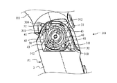
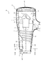
図15は本発明にかかるヘアードライヤのさらに他の例の断面図であり、図16は図15に示すヘアードライヤの上側から見た断面図である。図15、図16に示すヘアードライヤCは、ヒータ基板6c及び断熱スリーブ7cが異なる以外、図1等に示すヘアードライヤAと同じ構成を有している。そのため、ヘアードライヤAと実質同じ部分には、同じ符号を付してあるとともに、同じ部分の詳細な説明は省略する。また、図16において、本実施形態の構成では、イオン発生ユニット8の状態を示すため、整流部74に形成されているヒータ基板6cは省略している。
15 is a cross-sectional view of still another example of the hair dryer according to the present invention, and FIG. 16 is a cross-sectional view of the hair dryer shown in FIG. The hair dryer C shown in FIGS. 15 and 16 has the same configuration as the hair dryer A shown in FIG. 1 and the like except that the
図15に示すように、断熱スリーブ7cは、内部にヒータ5を配置するためのヒータ配置部72と、ヒータ配置部73の下流側に設けられ内部を流れる空気の流速を増加させる流速増速部73と、内部の気流の整流を行う整流部74とを備えている。ヒータ配置部72は下流側に行くにしたがって緩やかに小さくなるテーパー形状を有している。そして、流速増速部73は上部が急激に狭くなるような傾斜を有している。そのため、流速増速部73を通過する気流は増速(加速)される。ヒータ配置部72も内径が緩やかに小さくなっているため、気流は流速増速部73よりも緩やかに増速される。
As shown in FIG. 15, the
流速増速部73の傾斜部分は平面形状を有しており、流速増速部73の下流側に整流部74が連結している。整流部74は、上部に流速増速部73から連続して形成される平面部741を備えており、平面部741の上部にイオン発生ユニット8が配置されている。整流部74は平面部741を有しているため、断熱スリーブ7cの他の部分に比べて気流の流れ方向の断面積の減少が小さくなっている。
The inclined portion of the flow
断熱スリーブ7cの内部には、ヒータ5が取り付けられたヒータ基板6cが配置されている。ヒータ基板6cは、断熱スリーブ7cを上下に分割する水平板部61(第1板部)と、断熱スリーブ7cを左右に分割する垂直板部62(第2板部)とを十字状に組み合わせた形状を有している。そして、水平板部61及び垂直板部62は、断熱スリーブ7c(の内周面に配置された断熱コーン71)の内周面に接触して配置されており、断熱スリーブ7cは、ヒータ基板6cによって、分割されている。
Inside the
ヒータ基板6cの水平板部61は、断熱スリーブ7cの下流側の先端まで到達している。すなわち、断熱スリーブ7cはヒータ基板6cの水平板部61によって、上下に分割されている。図14に示すように、流速増速部73の水平板部61の上部は下部に比べて急激に断面積が小さくなっており、流速増速部73の水平板部61の上部では気流の流速が急激に増速する。そのため、流速増速部73の下流側に配置された整流部74において、水平板部61の上側の気流の流速は下側よりも速くなっている。
The
上述のとおり、イオン発生ユニット8は、整流部74の平面部741の上に配置されており、プラス電極81及びマイナス電極82は、断熱スリーブ7の整流部74の内部に向かって突出している。すなわち、イオン発生ユニット8は、断熱スリーブ7の整流部74の内部でイオンを発生するように配置されている。これにより、ヘアードライヤCは、流速が速い気流とともにイオンを遠くまで到達させることができる。
As described above, the
ヘアードライヤCにおいて、断熱スリーブ7c内部の気流はヒータ5を横切り、気流はヒータ5の電線によってせん断される。これにより、ヒータ5の下流では渦が発生しやすくなっており、気流が乱流になりやすい。そこで、ヘアードライヤCでは、断熱スリーブ7cのヒータ配置部72の下流側の整流部74で、気流を整流している。
In the hair dryer C, the airflow inside the
そして、断熱スリーブ7cにおいて、気流は流速増速部73で増速される。乱流を整流するため、断熱スリーブ7cはヒータ配置部72の下流側に十分な長さを有する整流部74を配置している。なお、整流部74の長さとしては、例えば、断熱スリーブ7cのヒータ配置部72の約1/3以上、断熱スリーブ7cの吐出口の外径以上等とすることが好ましい。
In the
また、整流部74では、水平板部61の上部が下部に比べ気流の流速が速くなっており、乱流を層流に遷移させる(整流する)ために必要な長さが異なる。そのため、垂直板部62は上下で異なる形状を有している。図14に示すように、水平板部61の上側に設けられた垂直板部62aは、水平板部61と同様に断熱スリーブ7cの下流側の先端まで到達している。一方、水平板部61の下側に設けられた垂直板部62bは、整流部74の途中までの形状となっている。
Moreover, in the rectification | straightening
つまり、整流部74の水平板部61の上部では気流の流れが速いため、垂直板部62aを先端部まで伸ばし、整流部74の実質的な長さを確保している。そして、垂直板部62aを先端部まで伸ばすことで、イオン発生ユニット8のプラス電極81とマイナス電極82とが突出している空間を分離することが可能となっている。これにより、発生したイオンが結びついてすぐに中和されるのを抑制することが可能となっている。
That is, since the airflow is fast at the upper portion of the
また、整流部74の水平板部61の下部では気流の流れが遅いため、垂直板部62bを整流部74の途中までとし、十分に整流するとともに、垂直板部62bで左右に分割された領域を流れた空気を混合することで、ヘアードライヤCの吐出口102から吐出される空気の温度むらを抑制している。
In addition, since the flow of the airflow is slow in the lower part of the
本発明のヘアードライヤCにおいて整流部74は、水平板部61と垂直板部62(62a、62b)とで流路を4分割して整流を行っているが、これに限定されず、さらに多数に分割してもよい。一般的に気流を乱流から層流に遷移させる場合、流路を細かく分割したほうが短い流路で整流できることが知られている。一方で、分割数を増やすと、流路に対する仕切部材が占める割合が増え、圧力損失の原因となる場合もある。また、ヘアードライヤCでは、整流部74でイオン発生ユニット8によるイオンを注入する構成となっている。そのため、整流部74の分割数として、4分割〜8分割程度の分割数であることが好ましい。
In the hair dryer C of the present invention, the rectifying
本発明にかかるヘアードライヤCでは、整流部74を設けて気流の整流を確実に行うことができるため、乱流では到達しなかった頭髪の内部(地肌の近く)に気流を到達させることができ、乾燥の効率を高めることができる。これにより、乾燥の効率が高くなることで乾燥に要する時間が短くなり、エネルギ(電力)の消費量を減らすことができる(省エネルギ化が可能である)。また、頭髪が高温の気流と接する時間を短くすることができ、頭髪の乾燥時のダメージを減らすことができる。
In the hair dryer C according to the present invention, since the air flow can be reliably rectified by providing the rectifying
また、断熱スリーブ7cの内部でイオンを発生させているので、別途イオンを発生させる流路を有する構成に比べて、無駄な流路を減らし、吐出口102から吐出られる気流の流量の減少を抑制することができる。また、無駄な流路を減らすことで、ヘアードライヤC自体を小型軽量化することが可能である。
In addition, since ions are generated inside the
(第5実施形態)
本発明にかかるヘアードライヤについて図面を参照して説明する。本発明にかかるヘアードライヤは、イオン発生装置で発生したイオンを気流とともに吐出し、頭髪等の乾燥対象物に吹付けるものである。本発明にかかるヘアードライヤはイオンを含む気流をより確実に対象物に吹付けることができる構成を有している。
(Fifth embodiment)
A hair dryer according to the present invention will be described with reference to the drawings. The hair dryer concerning this invention discharges the ion which generate | occur | produced with the ion generator with airflow, and sprays it on dry objects, such as hair. The hair dryer concerning this invention has the structure which can spray the airflow containing ion on a target object more reliably.
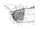
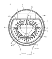
図17は本発明にかかるヘアードライヤを軸に沿って切断した断面図であり。図18は図17に示すヘアードライヤをXVIII−XVIII線で切断した断面図である。図17、図18に示すヘアードライヤDはヒータ5dの形状が異なる以外、図1、図4等に示すヘアードライヤAと同じ構成を有している。そのため、ヘアードライヤAと実質同じ部分には、同じ符号を付してあるとともに、同じ部分の詳細な説明は省略する。
FIG. 17 is a cross-sectional view of the hair dryer according to the present invention cut along an axis. 18 is a cross-sectional view of the hair dryer shown in FIG. 17 taken along line XVIII-XVIII. The hair dryer D shown in FIGS. 17 and 18 has the same configuration as the hair dryer A shown in FIGS. 1 and 4 except that the shape of the
図17に示すように、ヒータ5dは、ヒータ基板6に断熱スリーブ7内の気流の流れ方向に延びるらせん状に巻き回されている。ヘアードライヤDでは、ヘアードライヤAと同様、断熱スリーブ7の内部がヒータ基板6の水平板部61及び垂直板部62によって上下左右に分割(4分割)されている。このヒータ基板6によって分割された空間はそれぞれ気流が独立して流れ、各空間を流れた気流は断熱スリーブ7の下流側で混合される。
As shown in FIG. 17, the
ヒータ5dは、モータ15に近い部分では、ヒータ基板6の水平板部61の上下で同じ或いはほぼ同じ形状を有しており、図4に示すヒータ5と同様の形状を有している(すなわち、水平板部61を挟んで対称な形状を有している)。一方、イオン発生ユニット8に近い部分では、水平板部61の上側は下側に比べて低くなっている。
The
つまり、ヒータ5dのイオン発生ユニット8に近い部分では、図18示すように、ヒータ5dの水平板部61の上側は横方向に長い楕円形又は楕円に近い形状を有している。ヒータ5dの水平板部61の下側は円形又は円形に近い形状を有している。すなわち、ヒータ5dのイオン発生ユニット8に近い部分では、水平板部61を挟んで非対称な形状を有している。
That is, in the portion of the
そして、ヒータ5dは波型に折り曲げられた板状の電線であり、各波型の幅(ここでは、ピッチPt1とする)は同じ(略同じ)となっている。そのため、イオン発生ユニット8の近傍においてヒータ5dは、水平板部61の上側が下側に比べて波形状が少なくなっている(図18では上側12個、下側18個)。すなわち、ヒータ5dは、水平板部61の上側に配置される長さが、下側に配置される長さに比べて短くなる。そのため、ヒータ5dの水平板部61の上側に配置されている部分で発生する熱は、下側に配置されている部分に比べて少なくなる。これにより、ヒータ5dからイオン発生ユニット8に伝わる熱量を減らすことができる。
The
また、ヒータ5dの水平板部61の上側に配置されている部分を横方向に長い形状とすることで縦方向の長さが小さく形成されている。そのため、断熱スリーブ7とヒータ5dとの隙間を小さくすることができ、空間を有効利用することが可能である。これにより、ヘアードライヤD(の本体ケース1)を小型化することが可能である。
Moreover, the length of the vertical direction is formed small by making the part arrange | positioned above the
以上のような構成のヒータ5dを備えることで、吐出口102の近傍にイオン発生ユニット8を配置した場合でも、ヒータ5dからイオン発生ユニット8に伝達される熱を減らすことが可能である。これにより、イオン発生ユニット8が加熱されるのを抑制することができ、ヘアードライヤDの吐出口102から吐出される気流の熱量を減らすことなく、一定量のイオンを含む気流を吐出することが可能である。これにより使用者の利便性が高くなる。
By providing the
以上、本発明の実施形態について説明したが、本発明はこの内容に限定されるものではない。また本発明の実施形態は、発明の趣旨を逸脱しない限り、種々の改変を加えることが可能である。 As mentioned above, although embodiment of this invention was described, this invention is not limited to this content. The embodiments of the present invention can be variously modified without departing from the spirit of the invention.
本発明にかかるヘアードライヤは、内部に送風部と加熱部とを備えた本体ケースと、前記本体ケースに回動可能に取り付けられる把持部と、前記把持部の先端が前記本体ケースから最も離れた使用位置又は最も接近した収納位置にあるとき、前記把持部の回動を規制する節度部とを備え、前記節度部は前記本体ケース又は前記把持部の一方に設けられるとともに内側に向かって突出する第1係合部及び第2係合部を含む環状の内周面が形成された節度係合部と、前記本体ケース又は前記把持部の他方に固定される円環形状の係合体とを有しており、前記係合体は円環形状部と、前記円環形状部の径方向外側に突出するとともに径方向に弾性的に移動可能な凸部とを有しており、前記節度部は、前記把持部が前記使用位置にあるとき前記凸部が前記第1係合部と係合し、前記把持部が前記収納位置にあるとき前記凸部が前記第2係合部と係合することで把持部の回動を規制しており、前記第1係合部が、金属又はセラミックで形成されているとともに前記凸部と係合するように配置された節度ピンを有していることを特徴とする。 The hair dryer according to the present invention includes a main body case provided with an air blowing unit and a heating unit therein, a gripping unit rotatably attached to the main body case, and a tip of the gripping unit farthest from the main body case. And a moderation portion that restricts the rotation of the gripping portion when in the use position or the closest storage position, and the moderation portion is provided on one of the main body case or the gripping portion and protrudes inward. A moderation engagement portion formed with an annular inner peripheral surface including a first engagement portion and a second engagement portion; and an annular engagement body fixed to the other of the main body case or the grip portion. The engaging body has an annular shape portion and a convex portion protruding radially outward of the annular shape portion and elastically movable in the radial direction. When the grip portion is in the use position, the convex portion is The engaging portion is engaged with the first engaging portion, and the convex portion engages with the second engaging portion when the grasping portion is in the storage position, thereby restricting the rotation of the grasping portion. One engaging part is formed with a metal or ceramic, and has a moderation pin arranged so that it may engage with the convex part.
この構成によると、前記把持部が使用位置にあるとき、前記凸部と係合する前記第1係合部が金属又はセラミックで形成された節度ピンを用いており、前記凸部と前記節度ピンとが係合されるようになっている。このように構成されることで、前記第1係合部は前記把持部が回動するとき、前記凸部との摩擦による摩耗が発生しにくく、繰り返し使用した場合でも、前記凸部と前記第1係合部とがしっかり係合する。これにより、前記把持部が使用位置にあるとき、前記把持部のがたつきが抑制されるため、使用者が把持部を持ちながら振った場合でも、前記本体ケースがぶれにくい。このことから、使用者の利便性を高めることが可能である。
According to this configuration, when the grip portion is in the use position, the first engaging portion that engages with the convex portion uses a moderation pin made of metal or ceramic, and the convex portion and the moderation pin Are to be engaged. By being configured in this manner, the first engaging portion is less likely to be worn by friction with the convex portion when the gripping portion rotates, and even when used repeatedly, the first engaging portion and the first engaging
本発明にかかるヘアードライヤは、第2係合部の前記内周面から突出する突出量が、前記第1係合部の突出量よりも小さく形成されていてもよい。これにより、前記凸部と前記第2係合部との摩擦を低減することができ、前記凸部及び(又は)前記第2係合部の摩耗を低減することができる。 The hair dryer concerning this invention may be formed so that the protrusion amount which protrudes from the said internal peripheral surface of a 2nd engagement part is smaller than the protrusion amount of a said 1st engagement part. Thereby, friction between the convex portion and the second engaging portion can be reduced, and wear of the convex portion and / or the second engaging portion can be reduced.
本発明にかかるヘアードライヤは、前記第2係合部は前記節度係合部と一体的に形成されていてもよい。これにより、節度ピンを取り付ける作業を、第1係合部のみでよく、作業性を高めることができる。 In the hair dryer according to the present invention, the second engagement portion may be formed integrally with the moderation engagement portion. Thereby, the operation | work which attaches a moderation pin needs only a 1st engaging part, and can improve workability | operativity.
本発明にかかるヘアードライヤは、前記第2係合部は前記第1係合部と同様の金属又はセラミックで形成された節度ピンを有していてもよい。これにより、前記凸部と前記第1係合部及び前記第2係合部との摩擦を低減し、前記凸部、前記第1係合部及び前記第2係合部の摩耗を低減することができる。 In the hair dryer according to the present invention, the second engagement portion may have a moderation pin made of the same metal or ceramic as the first engagement portion. Thereby, friction between the convex part and the first engaging part and the second engaging part is reduced, and wear of the convex part, the first engaging part and the second engaging part is reduced. Can do.
本発明にかかるヘアードライヤは、前記第2係合部は前記第1係合部と同様の金属又はセラミックで形成された節度ピンを有しており、前記第2係合部の節度ピンは、前記第1係合部の節度ピンよりも小型に形成されていてもよい。これにより、第1係合部と第2係合部の突出量を正確に調整することができる。 In the hair dryer according to the present invention, the second engagement portion has a moderation pin formed of the same metal or ceramic as the first engagement portion, and the moderation pin of the second engagement portion is: The moderation pin of the first engaging portion may be formed smaller than the moderation pin. Thereby, the protrusion amount of a 1st engaging part and a 2nd engaging part can be adjusted correctly.
本発明にかかるヘアードライヤは、前記節度部は、前記把持部の回動の中心に対して点対称形状を有していてもよい。これにより、前記係合体に作用する力が相殺されるため、前記係合体が取り付けられる部材に作用する力を低減することができる。 In the hair dryer according to the present invention, the moderation portion may have a point-symmetric shape with respect to the center of rotation of the grip portion. Thereby, since the force which acts on the said engagement body is canceled, the force which acts on the member to which the said engagement body is attached can be reduced.
本発明にかかるヘアードライヤは、前記係合体は前記節度ピンに対し摺動性が高い材料で形成されている。これにより、前記凸部の摩耗を低減することが可能である。 In the hair dryer according to the present invention, the engagement body is formed of a material having a high slidability with respect to the moderation pin. Thereby, it is possible to reduce wear of the convex portion.
本発明にかかるヘアードライヤは、前記本体ケースが、内部に前記加熱部を配置するとともに内部を前記送風部からの気流が通過する先細りテーパー形状の断熱筒部と、前記断熱筒部の内部に配置され前記加熱部を保持するとともに、前記断熱筒部を周方向に分割する基板とを備えており、前記断熱筒部の気流の流れ方向下流側の端部は、一方向に前記テーパー形状の勾配よりも急な勾配の傾斜部を有する流速増速部と、前記傾斜部と連続するとともに、気流の流れ方向に沿って延びる平面部を有する整流部とを備えており、前記前記平面部の外面側にはイオン発生部が設けられており、前記イオン発生部のイオンを発生する電極が、前記断熱筒部の整流部に突出している。 In the hair dryer according to the present invention, the main body case is disposed inside the heat insulating tube portion, the tapered heat insulating tube portion in which the air flow from the air blowing portion passes and the heating portion disposed therein. And a substrate that divides the heat insulating cylinder part in the circumferential direction, and the end of the heat insulating cylinder part on the downstream side in the air flow direction has a tapered gradient in one direction. A flow velocity accelerating portion having an inclined portion with a steeper slope, and a rectifying portion having a flat portion that is continuous with the inclined portion and extends along the flow direction of the airflow, and the outer surface of the flat portion An ion generation part is provided on the side, and an electrode for generating ions of the ion generation part protrudes from the rectification part of the heat insulating cylinder part.
この構成によると、断熱筒部にイオン発生部を取り付けた構成となっているため、小型化、軽量化することが可能である。また、整流部で確実に整流した気流を吹き付けるため、気流が頭髪の内部に到達しやすく、それだけ、乾燥の効率を高めることができる。 According to this structure, since it has the structure which attached the ion generating part to the heat insulation cylinder part, it can be reduced in size and weight. Moreover, since the airflow reliably rectified by the rectifying unit is blown, the airflow easily reaches the inside of the hair, and the drying efficiency can be increased accordingly.
本発明にかかるヘアードライヤは、前記基板は十字状に組み立てられた第1板部と第2板部とを備えており、前記第1板部は前記平面部に沿うとともに、前記整流部全体を分割するように配置されており、前記第2板部は前記第1板部と交差するように設けられており、前記イオン発生部はプラス電極とマイナス電極とが前記第2板部を挟んで前記整流部に突出している。これにより、プラスに帯電したイオンとマイナスに帯電したイオンとが発生直後に結びつくのを抑制することができる。また、前記整流部が前記第1板部で前記平板部が形成されている側と反対側に分割されており、イオン発生部が配置されている側の流速が反対側に比べて速くなっている。イオン発生部で発生したイオンは流速が速い気流に乗ってヘアードライヤの外部に排出されるため、遠くまで(すなわち、毛髪の奥まで)届きやすい。 In the hair dryer according to the present invention, the substrate includes a first plate portion and a second plate portion assembled in a cross shape, and the first plate portion extends along the planar portion and the entire rectifying portion. The second plate portion is provided so as to intersect the first plate portion, and the ion generating portion includes a positive electrode and a negative electrode sandwiching the second plate portion. It protrudes from the rectifying unit. Thereby, it is possible to suppress the positively charged ions and the negatively charged ions from being combined immediately after generation. Further, the rectifying unit is divided on the side opposite to the side where the flat plate part is formed in the first plate part, and the flow velocity on the side where the ion generating part is arranged becomes faster than the opposite side. Yes. Since the ions generated in the ion generating unit are discharged to the outside of the hair dryer on an air current having a high flow velocity, they are easy to reach far away (that is, to the back of the hair).
本発明にかかるヘアードライヤは、前記第2板部の前記整流部内に配置されている部分は、前記第1板部を挟んで平面部側の部分が、反対側の部分よりも前記気流の流れ方向の下流側に長く形成されている。これにより、整流部の整流を行う実質的な長さを、流速が速い部分を長く、流速が遅い部分を短くしている。また、流速が遅い部分では、整流が行われた気流を早めに混合することで、気流の温度むらを抑制している。 In the hair dryer according to the present invention, the portion of the second plate portion arranged in the rectifying portion is such that the portion on the plane portion side with respect to the first plate portion is more airflow than the portion on the opposite side. It is formed long on the downstream side in the direction. Thereby, the substantial length which rectifies | straightens a rectification | straightening part is lengthened the part with a quick flow velocity, and shortened the part with a slow flow velocity. Further, in the portion where the flow velocity is slow, the air flow that has been rectified is mixed early to suppress the temperature unevenness of the air flow.
本発明にかかるヘアードライヤは、前記整流部の内部には、前記断熱筒部の他の部分よりも多くの領域に分割されるように基板が配置されている。これにより、より確実に整流を行うことが可能となる。なお、分割数としては4〜8程度が好ましく、基板の配置としては、放射状に配置するものを挙げることができる。 In the hair dryer according to the present invention, a substrate is arranged inside the rectifying unit so as to be divided into more regions than the other portions of the heat insulating cylinder portion. This makes it possible to perform rectification more reliably. Note that the number of divisions is preferably about 4 to 8, and the substrate may be arranged radially.
本発明にかかるヘアードライヤは、前記加熱部は等間隔に並んで形成された波形状を有する電線を、前記断熱筒部に沿うようにらせん状に巻き回した発熱部を備えており、前記発熱部は、前記らせん状の軸方向に見て、前記軸周りに対称形状となる対称部と、前記平面部と平行な面に対する鏡像と組み合わせたときの中心軸が前記らせん状の軸と重なる2つの異なる形状を前記らせん状の軸周りに対称とならないように組み合わせた非対称部とを備えており、前記非対称部は、前記らせん状の軸をとおり前記平面部と平行な面から突出する高さが、前記イオン発生部側に配置される部分が、反対側よりも低い。
The hair dryer according to the present invention is provided with a heat generating part in which the heating part is wound in a spiral shape so as to follow the heat insulating cylinder part, and the heat generating part is provided with a corrugated electric wire formed in equal intervals. The portion has a symmetrical portion that is symmetrical about the axis when viewed in the axial direction of the spiral, and a central axis that is combined with a mirror image of a plane parallel to the plane portion overlaps the
この構成によると、加熱部の前記らせん状の軸方向に前記イオン発生部に近い部分を非対称部とすることで、加熱部とイオン発生部とを一定間隔あけて配置することができる。これにより、イオン発生部が前記加熱部の熱によって誤作動したり、破損したりするのを抑制することが可能である。また、前記加熱部の発熱部として、波形状を変更せずに巻き回す形状のみを変更しているため、波形状のピッチを変更する構成に比べて組み付けが容易である。また、対称形状を有したままで、軸をイオン発生部から離すようにずらす方法に比べて、断熱筒部が大型化するのを抑制することができ、ヘアードライヤ自体が大きくなるのを抑制することができる。これにより、大型化することなくイオンを安定的に放出することができるので、使用者の利便性を高めることが可能である。 According to this structure, a heating part and an ion generation part can be arrange | positioned at fixed intervals by making the part close | similar to the said ion generation part in the said spiral axial direction of a heating part into an asymmetric part. Thereby, it is possible to suppress that the ion generation part malfunctions or is damaged by the heat of the heating part. Moreover, since only the shape which winds without changing a wave shape is changed as a heat-emitting part of the said heating part, an assembly | attachment is easy compared with the structure which changes the pitch of a wave shape. Moreover, compared with the method of shifting the axis away from the ion generating portion while maintaining the symmetrical shape, it is possible to suppress an increase in the size of the heat insulating cylindrical portion and to suppress an increase in the hair dryer itself. be able to. Thereby, since ion can be stably discharge | released without enlarging, it is possible to improve a user's convenience.
本発明にかかるヘアードライヤは、前記非対称部が、前記整流部の一部に形成されていてもよい。 In the hair dryer according to the present invention, the asymmetric part may be formed in a part of the rectifying part.
A〜D ヘアードライヤ
1 本体ケース
100 内部空間
101 吸込口
102 吐出口
11L 左ハウジング
11R 右ハウジング
111 ハンドル取付部
12 吸込みグリル
121 吸込みメッシュ
122 吸込みリング
13 吐出リング
131 吐出メッシュ
132 吐出リング
14 ファン
141 ファンケース
15 モータ
151 モータ用緩衝部材
16 通風路
2 ハンドル
20 ねじ
21L 左ハンドルカバー
21R 右ハンドルカバー
3 ヒンジ部
30 リング取付部
301 節度部
302 ストッパ部
31 節度リブ
310 ピン取付部
311 第1係合部
312 第2係合部
32 節度ピン
331 第1ストッパ部
332 第2ストッパ部
34 ガイド溝
35 規制リブ
36 係合凸部
4 ハンドルリング
41 凸部
42 弾性変形部
43 係合部
5、5d ヒータ
6 ヒータ基板
61 水平板部
62 垂直板部
7、7d 断熱スリーブ
71 断熱コーン
72 ヒータ配置部
73 流速増速部
74 整流部
741 平面部
8 イオン発生ユニット
80 本体
81 プラス電極
82 マイナス電極
Sw1 第1スイッチ
Sw2 第2スイッチ
Sw3 第3スイッチ
A to
Claims (7)
前記本体ケースに回動可能に取り付けられる把持部と、
前記把持部の先端が前記本体ケースから最も離れた使用位置又は最も接近した収納位置にあるとき、前記把持部の回動を規制する節度部とを備え、
前記節度部は前記本体ケース又は前記把持部の一方に設けられるとともに内側に向かって突出する第1係合部及び第2係合部を含む環状の内周面が形成された節度係合部と、
前記本体ケース又は前記把持部の他方に固定される円環形状の係合体とを有しており、
前記係合体は円環形状部と、前記円環形状部の径方向外側に突出するとともに径方向に弾性的に移動可能な凸部とを有しており、
前記節度部は、前記把持部が前記使用位置にあるとき前記凸部が前記第1係合部と係合し、前記把持部が前記収納位置にあるとき前記凸部が前記第2係合部と係合することで把持部の回動を規制しており、
前記第1係合部が、金属又はセラミックで形成されているとともに前記凸部と係合するように配置された節度ピンを有していることを特徴とするヘアードライヤ。 A main body case provided with an air blowing part and a heating part inside,
A gripping part rotatably attached to the main body case;
A moderation portion for restricting the rotation of the gripping portion when the tip of the gripping portion is at a use position furthest away from the main body case or a storage position closest to the main body case;
The moderation portion is provided on one of the main body case or the grip portion, and has a moderation engagement portion formed with an annular inner peripheral surface including a first engagement portion and a second engagement portion protruding inward. ,
Having an annular engagement body fixed to the other of the main body case or the gripping part,
The engaging body has an annular shape portion and a convex portion that protrudes radially outward of the annular shape portion and is elastically movable in the radial direction,
The moderation portion is configured such that when the grip portion is in the use position, the convex portion engages with the first engagement portion, and when the grip portion is in the storage position, the convex portion is the second engagement portion. Is engaged to regulate the rotation of the gripping part,
The hair dryer, wherein the first engaging portion is made of metal or ceramic and has a moderation pin disposed so as to engage with the convex portion.
前記断熱筒部の内部に配置され前記加熱部を保持するとともに、前記断熱筒部を周方向に分割する基板とを備えており、
前記断熱筒部の気流の流れ方向下流側の端部は、一方向に前記テーパー形状の勾配よりも急な勾配の傾斜部を有する流速増速部と、前記傾斜部と連続するとともに、気流の流れ方向に沿って延びる平面部を有する整流部とを備えており、
前記前記平面部の外面側にはイオン発生部が設けられており、
前記イオン発生部のイオンを発生する電極が、前記断熱筒部の整流部に突出している請求項1から請求項5のいずれかに記載のヘアードライヤ。 The main body case has a tapered tapered heat-insulating cylindrical portion in which the heating unit is disposed inside and an air flow from the blowing unit passes through the inside.
A substrate that is arranged inside the heat insulating cylinder part and holds the heating part, and that divides the heat insulating cylinder part in a circumferential direction, and
The end of the heat insulating cylinder portion on the downstream side in the flow direction of the air flow is continuous with the flow velocity accelerating portion having an inclined portion that is steeper than the gradient of the tapered shape in one direction, and the inclined portion. A rectifying part having a flat part extending along the flow direction,
An ion generating part is provided on the outer surface side of the flat part,
The hair dryer according to any one of claims 1 to 5, wherein an electrode for generating ions of the ion generating portion protrudes from a rectifying portion of the heat insulating cylinder portion.
前記発熱部は、前記らせん状の軸方向に見て、前記軸周りに対称形状となる対称部と、前記平面部と平行な面に対する鏡像と組み合わせたときの中心軸が前記らせん状の軸と重なる2つの異なる形状を前記らせん状の軸周りに対称とならないように組み合わせた非対称部とを備えており、
前記非対称部は、前記らせん状の軸をとおり前記平面部と平行な面から突出する高さが、前記イオン発生部側に配置される部分が、反対側よりも低い請求項6に記載のヘアードライヤ。 The heating part includes a heat generating part that spirally winds an electric wire having a wave shape formed side by side along the heat insulating cylinder part,
The heat generating portion has a symmetrical portion that is symmetrical about the axis when viewed in the helical axial direction, and a central axis when combined with a mirror image with respect to a plane parallel to the flat portion is the helical axis. An asymmetric part combining two different overlapping shapes so as not to be symmetric about the helical axis,
The hair according to claim 6, wherein a height of the asymmetric part protruding from a plane parallel to the flat part through the spiral axis is lower than that on the opposite side. Dryer.
Priority Applications (2)
| Application Number | Priority Date | Filing Date | Title |
|---|---|---|---|
| JP2013211744A JP6271208B2 (en) | 2013-10-09 | 2013-10-09 | Hair dryer |
| CN201420559896.2U CN204120442U (en) | 2013-10-09 | 2014-09-26 | Hair-dryer |
Applications Claiming Priority (1)
| Application Number | Priority Date | Filing Date | Title |
|---|---|---|---|
| JP2013211744A JP6271208B2 (en) | 2013-10-09 | 2013-10-09 | Hair dryer |
Publications (2)
| Publication Number | Publication Date |
|---|---|
| JP2015073726A true JP2015073726A (en) | 2015-04-20 |
| JP6271208B2 JP6271208B2 (en) | 2018-01-31 |
Family
ID=52376841
Family Applications (1)
| Application Number | Title | Priority Date | Filing Date |
|---|---|---|---|
| JP2013211744A Active JP6271208B2 (en) | 2013-10-09 | 2013-10-09 | Hair dryer |
Country Status (2)
| Country | Link |
|---|---|
| JP (1) | JP6271208B2 (en) |
| CN (1) | CN204120442U (en) |
Cited By (7)
| Publication number | Priority date | Publication date | Assignee | Title |
|---|---|---|---|---|
| WO2016181675A1 (en) * | 2015-05-12 | 2016-11-17 | シャープ株式会社 | Hair care method and hair care instrument for use in said method |
| JP2017077471A (en) * | 2015-10-21 | 2017-04-27 | ダイソン テクノロジー リミテッド | Handheld appliances |
| US10085538B2 (en) | 2015-10-21 | 2018-10-02 | Dyson Technology Limited | Hand held appliance |
| JP2018171243A (en) * | 2017-03-31 | 2018-11-08 | テスコム電機株式会社 | Hair dryer in which air path is improved |
| JP2020199296A (en) * | 2018-12-27 | 2020-12-17 | アイリスオーヤマ株式会社 | Dryer |
| JP2024531019A (en) * | 2022-08-17 | 2024-08-29 | 深▲せん▼淑格医▲療▼美容器械有限公司 | Double Duct Hair Dryer |
| CN119267567A (en) * | 2024-12-11 | 2025-01-07 | 江苏恒大风机有限公司 | A fire damper for flue smoke exhaust |
Families Citing this family (1)
| Publication number | Priority date | Publication date | Assignee | Title |
|---|---|---|---|---|
| CN110975079B (en) * | 2019-12-26 | 2025-09-19 | 苏州雾联医疗科技有限公司 | Heatable atomizer |
Citations (10)
| Publication number | Priority date | Publication date | Assignee | Title |
|---|---|---|---|---|
| JPS5992918U (en) * | 1982-12-15 | 1984-06-23 | 日本電熱株式会社 | Knob rotation control device |
| JPS59125305U (en) * | 1983-02-14 | 1984-08-23 | 東芝熱器具株式会社 | hair dryer |
| JPS6189304U (en) * | 1984-11-16 | 1986-06-11 | ||
| JPH0277207A (en) * | 1988-09-14 | 1990-03-16 | Matsushita Electric Works Ltd | Folding system hair dryer |
| JP2008126139A (en) * | 2006-11-21 | 2008-06-05 | Matsushita Electric Works Ltd | Electrostatic atomizing device and ion dryer using the same |
| JP2008200153A (en) * | 2007-02-17 | 2008-09-04 | Kyushu Hitachi Maxell Ltd | Hair dryer |
| JP2009233366A (en) * | 2009-07-15 | 2009-10-15 | Kyushu Hitachi Maxell Ltd | Hair dryer |
| JP2009261514A (en) * | 2008-04-23 | 2009-11-12 | Panasonic Electric Works Co Ltd | Hair dryer |
| JP2011067318A (en) * | 2009-09-25 | 2011-04-07 | Panasonic Electric Works Co Ltd | Hair care device |
| US20130008043A1 (en) * | 2011-07-07 | 2013-01-10 | Carroll B. Correll, Jr. | Hair dryer with dual axis rotatable handle |
-
2013
- 2013-10-09 JP JP2013211744A patent/JP6271208B2/en active Active
-
2014
- 2014-09-26 CN CN201420559896.2U patent/CN204120442U/en not_active Expired - Lifetime
Patent Citations (10)
| Publication number | Priority date | Publication date | Assignee | Title |
|---|---|---|---|---|
| JPS5992918U (en) * | 1982-12-15 | 1984-06-23 | 日本電熱株式会社 | Knob rotation control device |
| JPS59125305U (en) * | 1983-02-14 | 1984-08-23 | 東芝熱器具株式会社 | hair dryer |
| JPS6189304U (en) * | 1984-11-16 | 1986-06-11 | ||
| JPH0277207A (en) * | 1988-09-14 | 1990-03-16 | Matsushita Electric Works Ltd | Folding system hair dryer |
| JP2008126139A (en) * | 2006-11-21 | 2008-06-05 | Matsushita Electric Works Ltd | Electrostatic atomizing device and ion dryer using the same |
| JP2008200153A (en) * | 2007-02-17 | 2008-09-04 | Kyushu Hitachi Maxell Ltd | Hair dryer |
| JP2009261514A (en) * | 2008-04-23 | 2009-11-12 | Panasonic Electric Works Co Ltd | Hair dryer |
| JP2009233366A (en) * | 2009-07-15 | 2009-10-15 | Kyushu Hitachi Maxell Ltd | Hair dryer |
| JP2011067318A (en) * | 2009-09-25 | 2011-04-07 | Panasonic Electric Works Co Ltd | Hair care device |
| US20130008043A1 (en) * | 2011-07-07 | 2013-01-10 | Carroll B. Correll, Jr. | Hair dryer with dual axis rotatable handle |
Cited By (9)
| Publication number | Priority date | Publication date | Assignee | Title |
|---|---|---|---|---|
| WO2016181675A1 (en) * | 2015-05-12 | 2016-11-17 | シャープ株式会社 | Hair care method and hair care instrument for use in said method |
| JP2017077471A (en) * | 2015-10-21 | 2017-04-27 | ダイソン テクノロジー リミテッド | Handheld appliances |
| US10085538B2 (en) | 2015-10-21 | 2018-10-02 | Dyson Technology Limited | Hand held appliance |
| JP2018171243A (en) * | 2017-03-31 | 2018-11-08 | テスコム電機株式会社 | Hair dryer in which air path is improved |
| JP2020199296A (en) * | 2018-12-27 | 2020-12-17 | アイリスオーヤマ株式会社 | Dryer |
| JP6998622B2 (en) | 2018-12-27 | 2022-02-10 | アイリスオーヤマ株式会社 | Dryer |
| JP2024531019A (en) * | 2022-08-17 | 2024-08-29 | 深▲せん▼淑格医▲療▼美容器械有限公司 | Double Duct Hair Dryer |
| JP7673247B2 (en) | 2022-08-17 | 2025-05-08 | 深▲せん▼淑格医▲療▼美容器械有限公司 | Double Duct Hair Dryer |
| CN119267567A (en) * | 2024-12-11 | 2025-01-07 | 江苏恒大风机有限公司 | A fire damper for flue smoke exhaust |
Also Published As
| Publication number | Publication date |
|---|---|
| CN204120442U (en) | 2015-01-28 |
| JP6271208B2 (en) | 2018-01-31 |
Similar Documents
| Publication | Publication Date | Title |
|---|---|---|
| JP6271208B2 (en) | Hair dryer | |
| CN207168088U (en) | Hand device | |
| AU2022213518B2 (en) | A haircare appliance | |
| CN218791006U (en) | Hair care implement | |
| US20240115027A1 (en) | Haircare appliance | |
| US20240081505A1 (en) | Haircare appliance | |
| US20240298772A1 (en) | Haircare appliance | |
| GB2603176A (en) | A haircare appliance | |
| CN218791007U (en) | Accessories for hair care appliances and hair care appliances | |
| CN104968235A (en) | nozzle for hair dryer | |
| CN107224086A (en) | Annex for hand-held instruments | |
| CN219088594U (en) | Accessories for hair care appliances and hair care appliances | |
| US20240277127A1 (en) | Haircare appliance | |
| CN116685236B (en) | Hair care appliance | |
| US20180055183A1 (en) | Handheld appliance | |
| GB2603174A (en) | A haircare appliance | |
| JP4131235B2 (en) | Eyelash forming tool | |
| GB2631011A (en) | A haircare appliance | |
| WO2025092996A1 (en) | Hair care apparatus | |
| GB2641396A (en) | Attachment for a haircare appliance | |
| JP2020081140A (en) | Hair dryer | |
| WO2026031763A1 (en) | Airflow guide nozzle and hair care appliance | |
| JP2024126080A (en) | Hair dryer | |
| CN121511035A (en) | Accessories for hair care tools and hair care tools |
Legal Events
| Date | Code | Title | Description |
|---|---|---|---|
| A621 | Written request for application examination |
Free format text: JAPANESE INTERMEDIATE CODE: A621 Effective date: 20160923 |
|
| A977 | Report on retrieval |
Free format text: JAPANESE INTERMEDIATE CODE: A971007 Effective date: 20170619 |
|
| A131 | Notification of reasons for refusal |
Free format text: JAPANESE INTERMEDIATE CODE: A131 Effective date: 20170627 |
|
| A521 | Request for written amendment filed |
Free format text: JAPANESE INTERMEDIATE CODE: A523 Effective date: 20170825 |
|
| RD03 | Notification of appointment of power of attorney |
Free format text: JAPANESE INTERMEDIATE CODE: A7423 Effective date: 20170825 |
|
| TRDD | Decision of grant or rejection written | ||
| A01 | Written decision to grant a patent or to grant a registration (utility model) |
Free format text: JAPANESE INTERMEDIATE CODE: A01 Effective date: 20171205 |
|
| A61 | First payment of annual fees (during grant procedure) |
Free format text: JAPANESE INTERMEDIATE CODE: A61 Effective date: 20171227 |
|
| R150 | Certificate of patent or registration of utility model |
Ref document number: 6271208 Country of ref document: JP Free format text: JAPANESE INTERMEDIATE CODE: R150 |