JP2015073725A - Medical diagnostic imaging apparatus and focus size calibration method - Google Patents
Medical diagnostic imaging apparatus and focus size calibration method Download PDFInfo
- Publication number
- JP2015073725A JP2015073725A JP2013211714A JP2013211714A JP2015073725A JP 2015073725 A JP2015073725 A JP 2015073725A JP 2013211714 A JP2013211714 A JP 2013211714A JP 2013211714 A JP2013211714 A JP 2013211714A JP 2015073725 A JP2015073725 A JP 2015073725A
- Authority
- JP
- Japan
- Prior art keywords
- ray
- grid
- size
- control unit
- focus
- Prior art date
- Legal status (The legal status is an assumption and is not a legal conclusion. Google has not performed a legal analysis and makes no representation as to the accuracy of the status listed.)
- Granted
Links
Images


Landscapes
- X-Ray Techniques (AREA)
- Apparatus For Radiation Diagnosis (AREA)
Abstract
Description
本発明の実施形態は、医用画像診断装置および焦点サイズ校正方法に関する。 Embodiments described herein relate generally to a medical image diagnostic apparatus and a focus size calibration method.
X線アンギオ装置をはじめとするX線診断装置やX線CT装置などのX線管を備えた医用画像診断装置には、X線管の焦点サイズを変更可能なものがある。 Some medical image diagnostic apparatuses equipped with an X-ray tube such as an X-ray diagnostic apparatus such as an X-ray angio apparatus and an X-ray CT apparatus can change the focal size of the X-ray tube.
X線管の焦点サイズは、X線撮影の対象物に対して照射される線量およびX線撮影により得られる画像の解像度に影響する。具体的には、焦点サイズが小さいほど線量が弱くなる一方解像度を高くすることができ、焦点サイズが大きいほど半影により解像度が落ちるが線量は多くとるこができる。このため、X線管の焦点サイズを複数設定可能あるいは任意に変更可能であると、X線撮影の対象物に応じて線量や解像度を変更することができ便利である。 The focal spot size of the X-ray tube affects the dose irradiated to the X-ray imaging target and the resolution of the image obtained by the X-ray imaging. Specifically, the smaller the focal spot size, the weaker the dose, while the higher the resolution, and the larger the focal spot size, the lower the resolution due to the penumbra, but the larger the dose. For this reason, if a plurality of focus sizes of the X-ray tube can be set or arbitrarily changed, it is convenient that the dose and resolution can be changed according to the X-ray imaging target.
X線管の焦点サイズを可変とする方法として、グリッド電極を有するX線管を用い、グリッド電圧に応じて焦点サイズを変更する方法が知られている。しかし、X線管は個体ごとに特性が異なる。また、焦点サイズの許容誤差を考慮するとグリッド電圧の変化に対する焦点サイズの変化が大きい。また、グリッド電極に電圧を印加する電源は一般に高電圧電源が用いられるため、この電源に設定された出力電圧と実際に出力される電圧とを正確に合わせることも難しい。このため、焦点サイズとグリッド電圧との関係を正確に設定することは難しい。 As a method for changing the focal size of the X-ray tube, a method is known in which an X-ray tube having a grid electrode is used and the focal size is changed according to the grid voltage. However, X-ray tubes have different characteristics for each individual. Further, when the tolerance of the focus size is taken into consideration, the change in the focus size with respect to the change in the grid voltage is large. In addition, since a high voltage power supply is generally used as a power supply for applying a voltage to the grid electrode, it is difficult to accurately match the output voltage set for this power supply with the actually output voltage. For this reason, it is difficult to accurately set the relationship between the focal spot size and the grid voltage.
また、焦点サイズとグリッド電圧との関係について、医用画像診断装置の出荷時に工場にて正確に設定したとしても、X線管およびグリッド電圧制御系の経年変化により、上記関係は設定時とは異なってしまうことが多い。また、X線管の特性やグリッド電圧制御系の特性を医用画像診断装置の設置されている場所でユーザが正確に測定することは難しい。このため、医用画像診断装置の設置後にユーザによりX線管が交換された場合、焦点サイズとグリッド電圧との関係を校正することは極めて難しい。 Even if the relationship between the focus size and the grid voltage is accurately set at the factory when the medical diagnostic imaging apparatus is shipped, the above relationship is different from that at the time of setting due to aging of the X-ray tube and the grid voltage control system. It often happens. In addition, it is difficult for the user to accurately measure the characteristics of the X-ray tube and the characteristics of the grid voltage control system at the place where the medical image diagnostic apparatus is installed. For this reason, when the X-ray tube is replaced by the user after the installation of the medical image diagnostic apparatus, it is extremely difficult to calibrate the relationship between the focus size and the grid voltage.
本発明の一実施形態に係る医用画像診断装置は、上述した課題を解決するために、X線管、X線検出部、グリッド制御部、X線光学部、画像解析部および主制御部を備える。X線管は、グリッドを有し、グリッド電圧に応じて焦点サイズが変化する。X線検出部は、このX線管と対向する位置に設けられる。グリッド制御部は、設定グリッド電圧に応じてグリッド電圧を生成しグリッドに印加する。X線光学部は、X線管とX線検出部との間に設置され、X線管の焦点像をX線検出部に結像させる。画像解析部は、X線管から照射されてX線光学部を介してX線検出部に結像された焦点像のサイズを出力する。主制御部は、グリッド制御部に対して設定グリッド電圧を出力するとともに、出力した設定グリッド電圧に応じて結像された焦点像のサイズにもとづいてX線管の焦点サイズを求め、求めた焦点サイズとグリッド制御部に出力した設定グリッド電圧とを関連付けた情報を生成する。 In order to solve the above-described problem, a medical image diagnostic apparatus according to an embodiment of the present invention includes an X-ray tube, an X-ray detection unit, a grid control unit, an X-ray optical unit, an image analysis unit, and a main control unit. . The X-ray tube has a grid, and the focal spot size changes according to the grid voltage. The X-ray detector is provided at a position facing the X-ray tube. The grid control unit generates a grid voltage according to the set grid voltage and applies it to the grid. The X-ray optical unit is installed between the X-ray tube and the X-ray detection unit, and forms a focus image of the X-ray tube on the X-ray detection unit. The image analysis unit outputs the size of the focus image irradiated from the X-ray tube and imaged on the X-ray detection unit via the X-ray optical unit. The main control unit outputs the set grid voltage to the grid control unit, obtains the focal size of the X-ray tube based on the size of the focused image formed in accordance with the outputted set grid voltage, and obtains the obtained focus Information that associates the size with the set grid voltage output to the grid control unit is generated.
本発明に係る医用画像診断装置および焦点サイズ校正方法の実施の形態について、添付図面を参照して説明する。 Embodiments of a medical image diagnostic apparatus and a focus size calibration method according to the present invention will be described with reference to the accompanying drawings.
本発明の一実施形態に係る医用画像診断装置は、グリッドを有しグリッド電圧に応じて焦点サイズが変化するX線管を備えたX線CTやX線アンギオ装置などの各種の医用画像診断装置に適用することが可能である。 A medical image diagnostic apparatus according to an embodiment of the present invention includes various medical image diagnostic apparatuses such as an X-ray CT and an X-ray angio apparatus that include an X-ray tube having a grid and a focal point size that changes in accordance with the grid voltage. It is possible to apply to.
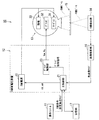
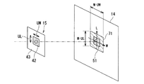
図1は、本発明の一実施形態に係る医用画像診断装置10の一構成例を示すブロック図である。
FIG. 1 is a block diagram illustrating a configuration example of a medical image
医用画像診断装置10は、操作コンソール11、X線高電圧装置12、X線管13、X線検出部14、X線光学部15、画像解析部16および記憶部17を有する。
The medical image
操作コンソール11は、ユーザによる操作を受け付けるための操作受付部や各種画像を表示するための表示出力部を備え、ユーザによるX線照射条件(X線条件)や設定焦点サイズなどの入力を受け付けてX線高電圧装置12に与える。
The
操作受付部は、たとえばキーボード、タッチパネル、テンキーなどの一般的な入力装置により構成され、ユーザの操作に対応した操作入力信号を主制御部21に出力する。表示出力部は、たとえば液晶ディスプレイやOLED(Organic Light Emitting Diode)ディスプレイなどの一般的な表示出力装置により構成され、入力受付のための画像などの各種画像を表示する。
The operation reception unit is configured by a general input device such as a keyboard, a touch panel, or a numeric keypad, and outputs an operation input signal corresponding to a user operation to the
操作コンソール11は、たとえば一般的なパーソナルコンピュータにより構成されてもよい。操作コンソール11がパーソナルコンピュータにより構成される場合、操作コンソール11、画像解析部16は同一のパーソナルコンピュータにより実現されてもよく、また記憶部17はこのパーソナルコンピュータにより備えられた記憶媒体であってもよい。
The
X線高電圧装置12は、主制御部21、X線電源22およびグリッド制御部23を有する。
The X-ray
主制御部21は、CPU、RAMおよびROMをはじめとする記憶媒体などにより構成され、この記憶媒体に記憶された焦点サイズ校正プログラムに従ってX線高電圧装置12の動作を制御する。
The
具体的には、主制御部21は、グリッド制御部23に対して設定グリッド電圧VSGに対応するグリッド制御信号を出力する。たとえば記憶部17または主制御部21の記憶媒体に焦点サイズと設定グリッド電圧VSGとを関連付けた情報が記憶されている場合、主制御部21は、たとえば操作コンソール11から与えられた設定焦点サイズに関連付けられた設定グリッド電圧VSGを抽出し、この設定グリッド電圧VSGに対応するグリッド制御信号をグリッド制御部23に与える。
Specifically, the
また、主制御部21は、出力した設定グリッド電圧VSGに応じてX線検出部14に結像された焦点像のサイズを画像解析部16から受けると、この焦点像のサイズにもとづいてX線管13の焦点サイズを求める。そして、求めた焦点サイズとグリッド制御部23に出力した設定グリッド電圧VSGとを関連付けた情報を生成し、記憶部17または主制御部21の記憶媒体に記憶させる。焦点サイズと設定グリッド電圧VSGとを関連付けた情報が既に記憶されている場合は、生成した情報でこの既に記憶されている情報を更新する。
The
また、主制御部21は、操作コンソール11から受けたX線条件にもとづいてX線管13に印加すべき管電圧kVや管電流mA、照射時間(管電流、管電圧の印加期間)msecなどを設定してX線電源22に与える。また、X線管13が回転陽極タイプである場合は、主制御部21は、X線電源22の内部のステータコイル駆動回路を介してX線管13のターゲット31を回転させる。
Further, the
X線電源22は、主制御部21に制御されて、X線管13に印加すべき管電圧kVや管電流mAをX線管13に供給する。また、X線管13が回転陽極タイプである場合は、X線電源22の内部のステータコイル駆動回路を介してX線管13のターゲット31を回転させる。
The
グリッド制御部23は、主制御部21に制御されて、設定グリッド電圧VSGに対応するグリッド制御信号に応じてグリッド電圧VGを生成し、X線管13のグリッド32に印加することによりX線管13の焦点サイズを制御する。
The
陰極33は、X線電源22のフィラメント加熱回路により管電流mAを制御されて加熱されると、熱電子を放出できる状態になる。この状態でターゲット31がステータコイル駆動回路により回転し、X線管13に管電圧kVが印加されると、熱電子がターゲット31に衝突してX線が照射される。このとき、グリッド制御部23によりグリッド32に負の電圧(グリッド電圧VG)が印加されると、X線管13の陰極33から放出された熱電子束は絞りこまれ、ターゲット31上の衝突面積が小さくなり、X線管13の焦点サイズは小さくなる。このため、グリッド電圧VGを制御することにより、X線管13の焦点サイズを制御することができる。グリッド制御部23は、グリッド制御信号に応じてたとえば−3000Vから0Vまでの電圧をグリッド電圧VGとしてグリッド32に印加可能に構成される。
When the
なお、以下の説明では、グリッド32がX線管13の焦点の幅W方向および長さL方向のそれぞれを制御するための2組備えられ、グリッド制御部23がこの2組のグリッド32のそれぞれに対してグリッド電圧VGW、VGLを印加する場合の例について示す。2組のグリッド32を用い、それぞれに別の電圧を印加することにより、焦点形状を2次元的に変更することができ、たとえば焦点形状を正方形に近づけることができる。
In the following description, two sets of
X線管13は、ターゲット31、グリッド32および陰極(カソードフィラメント)33を有する。陰極33は1つであってもよい。X線管13の焦点サイズは、グリッド32に印加されるグリッド電圧VGW、VGLに応じて変化する。なお、ターゲット31は回転しない固定陽極タイプであってもよいし、回転する回転陽極タイプであってもよい。
The
X線検出部14、X線光学部15を挟んでX線管13と対向する位置に設けられ、X線検出部14に照射されたX線を検出する。X線検出部14は、この検出したX線の強度に応じた信号を画像解析部16に出力する。
It is provided at a position facing the
医用画像診断装置10としてX線CT装置を用いる場合は、X線検出部14はたとえば回転するガントリによりX線管13と対向する位置にX線管13と一体として保持され、たとえば2次元に配置された複数のX線検出素子(電荷蓄積素子)により構成される。また、医用画像診断装置10としてX線アンギオ装置を用いる場合は、X線検出部14はCアームによりX線管13と対向する位置にX線管13と一体として保持され、たとえば平面検出器(FPD:flat panel detector)により構成される。
When an X-ray CT apparatus is used as the medical image
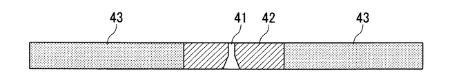
X線光学部15は、X線管13の焦点像をX線検出部14に結像させるための光学系であり、結像要素41と、結像要素41を囲む周囲要素42と、周囲要素42を支持する基板43とを有する。X線管13から照射されたX線ビームは、X線錐の中心位置に設置された結像要素41により絞りこまれ、X線検出部14にX線管13の焦点像を結像させる。
The X-ray
図2は、ピンホールカメラ法を利用する場合におけるX線光学部15の断面図である。
FIG. 2 is a cross-sectional view of the X-ray
X線光学部15の結像要素41としては、たとえば図2に示すようにピンホールカメラ法(医用X線管装置 JIS Z 4704)に用いられるピンホールを用いることができる。結像要素41としてピンホールを用いる場合、周囲要素42は金90%と白金10%の合金やタングステンまたはタングステンカーバイドなどにより構成され、結像要素41は、周囲要素42にピンホールとして形成される。基板43は、周囲要素42を支持することができればよく、鉛、鉄などの金属で構成されてもよいし、アクリル板などの非金属で構成されてもよい。
As the
なお、X線光学部15は、画像解析部16がX線管13の焦点像のサイズを出力できるようにX線管13の焦点像に相当する像をX線検出部14に結像することができればよく、たとえば結像要素41としてX線集光レンズを用いてもよい。また、結像要素41としてピンホールカメラ法におけるピンホールと同等の径を有する鉛などのX線遮蔽物を用い、周囲要素42をアクリル板などの結像要素41よりもX線透過率の高い物質で構成してもよい。
The X-ray
画像解析部16は、X線管13から照射されてX線光学部15を介してX線検出部14に結像された焦点像のサイズを出力する。
The
図3は、結像要素41としてピンホールを用いる場合において、X線検出部14に結像されたX線管13の焦点像51のサイズから焦点サイズを求める方法の一例を説明するための説明図である。
FIG. 3 is an explanatory diagram for explaining an example of a method for obtaining a focal size from the size of the
ピンホールカメラ法では、ピンホールの径がX線管13の焦点サイズよりも十分に小さいとき、X線管13の焦点位置52からピンホールまでの距離をA、ピンホールからX線検出部14までの距離をBとすると、W方向にΔW、L方向にΔLのサイズを有する焦点が、拡大率(倍率)M=B/Aで拡大された焦点像51としてX線検出部14に結像することが知られている。X線検出部14が出力する画像信号はX線検出部14に照射されたX線の強度分布信号であり、ピンホールを通過してX線検出部14に照射されるX線の強度は強く、周囲要素42で遮られたX線の強度は弱い。
In the pinhole camera method, when the diameter of the pinhole is sufficiently smaller than the focal size of the
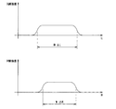
図4は、図3に示す例においてX線検出部14が出力する幅W方向および長さL方向のX線強度分布の一例を示す説明図である。
FIG. 4 is an explanatory diagram illustrating an example of the X-ray intensity distribution in the width W direction and the length L direction output from the
X線検出部14が出力するX線強度分布をW方向およびL方向についてそれぞれグラフにすると、図4に示すように台形状になる。このため、画像解析部16は、X線検出部14の出力にもとづいて、各台形の上底と下底の中央に閾値を設け、閾値を超える部分の距離を測定することで焦点像51のW方向およびL方向のサイズを得ることができる。
If the X-ray intensity distribution output from the
したがって、主制御部21は、画像解析部16から受けた焦点像51のサイズを拡大率Mで除すことにより、X線管13の焦点サイズを求めることができる。
Therefore, the
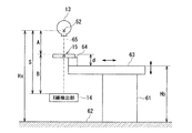
図5は、X線光学部15が寝台61に支持される様子の一例を示す説明図である。
FIG. 5 is an explanatory diagram illustrating an example of a state in which the X-ray
拡大率Mは、正確に設定するためには、X線管13、X線検出部14およびX線光学部15を正確に位置決めすることが重要である。これらを正確に位置決めするためには、たとえばX線光学部15を寝台61に支持させるとよい。
In order to set the enlargement ratio M accurately, it is important to accurately position the
この場合、寝台61は、床面62に載置され、被検体を載置する天板63を有する。天板63の一部、たとえば天板63のX線照射軸側の先端には、X線光学部15を支持する支持部材64が設けられる。支持部材64は、たとえば天板63からX線照射軸側に突出するように、X線光学部15を支持する。X線光学部15の結像要素41は、X線錐の中心に位置するようにたとえばレーザマーカ65を用いて位置決めされる。
In this case, the
X線管13およびX線検出部14は、天板63の上面の法線方向に沿った所定位置で停止させておくとよい。この所定位置における焦点位置52と床面62との距離Hxはあらかじめ測定しておく。また、焦点位置52とX線検出部14の検出面との距離Sは既知である。また、天板63の上面から支持部材64に支持されたX線光学部15までの高さdも既知の一定値である。したがって、床面62から天板63の上面までの高さHbを制御することにより、拡大率Mを制御することができる。床面62から天板63の上面までの高さHbは、たとえば主制御部21が寝台61の駆動機構を制御することにより任意に設定することができる。
The
図6は、周囲要素42の像にもとづいて拡大率Mを算出する様子の一例を示す説明図である。
FIG. 6 is an explanatory diagram showing an example of how the enlargement factor M is calculated based on the image of the surrounding
周囲要素42と基板43とが異なるX線透過率を有する場合、X線検出部14には周囲要素42の輪郭UW×ULの像71が結像される。この場合、画像解析部16は、この周囲要素42の輪郭の像71のサイズM・UWおよびM・ULを出力するとよい。主制御部21は、この輪郭の像71のサイズを、X線光学部15上での周囲要素42の実際の輪郭のサイズで除すことにより、拡大率Mを求めることができる。
When the surrounding
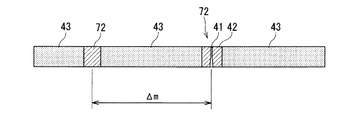
図7は、X線光学部15の複数のマーカ72の像にもとづいて拡大率Mを算出する様子の一例を示す説明図である。
FIG. 7 is an explanatory diagram showing an example of how the magnification rate M is calculated based on the images of the plurality of
X線検出部14に識別可能な像が結像される複数のマーカ72をX線光学部15に設け、複数のマーカ72の像の間の距離を用いて拡大率Mを求めることもできる。マーカ72は、X線検出部14に識別可能な像が結像されるものであればよく、マーカ72とその周囲の部材とのX線透過率が異なっていればよい。
A plurality of
また、マーカ72の1つとして結像要素41を利用してもよい。結像要素41と周囲要素42とは当然にX線透過率が異なるためである。図7には、マーカ72の1つとしてピンホールの結像要素41を利用する場合の例を示した。また、たとえば基板43を鉛で構成している場合は、マーカ72の1つまたは複数は鉄やアクリルなどで構成されてもよいし、基板43に設けられた開口部であってもよい。
Further, the
画像解析部16は、X線検出部14に結像された複数のマーカ72の像の中心位置を求め、この中心位置間の距離を出力する。主制御部21は、この中心位置間の距離を、X線光学部15上での複数のマーカ72の距離Δmで除すことにより、拡大率Mを求めることができる。
The
周囲要素42の像にもとづいて拡大率Mを算出する方法や、X線光学部15の複数のマーカ72の像にもとづいて拡大率Mを算出する方法によれば、実測にもとづく拡大率Mを用いて焦点サイズを正確に求めることができる。また、この場合、X線光学部15の位置からB/Aを求めて拡大率Mを算出する必要がないため、X線光学部15の位置合わせを精密に行う必要がなく、またX線光学部15の位置を知る必要もない。
According to the method of calculating the magnification rate M based on the image of the surrounding
次に、本実施形態に係る医用画像診断装置10の動作の一例について説明する。
Next, an example of the operation of the medical image
医用画像診断装置10による焦点サイズの校正方法としては、大きく次の2つの方法を用いることができる。
As a method for calibrating the focus size by the medical image
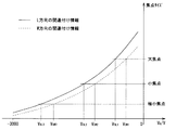
まず、焦点サイズの第1の校正方法について説明する。第1の校正方法は、設定焦点サイズに対応する設定グリッド電圧VSGを求めることにより焦点サイズとグリッド電圧との関係を校正し、ユーザの所望する設定焦点サイズを正確に実現する方法である。第1の校正方法では、焦点サイズとグリッド電圧VGとをあらかじめ関連付けた情報(X線管13の標準特性情報)を、記憶部17または主制御部21の記憶媒体に記憶させておく。以下の説明では、標準特性情報が記憶部17に記憶されている場合の例について示す。
First, the first calibration method for the focus size will be described. First calibration method is to calibrate the relationship between the focal spot size and the grid voltage by obtaining the setting grid voltage VS G corresponding to the set focal spot size, a method of accurately realizing the setting focus size desired user is. In a first calibration method, previously associated information (standard characteristic information of the X-ray tube 13) and the focal spot size and the grid voltage V G, stored in a storage medium of the
図8は、W方向およびL方向のそれぞれについて焦点サイズとグリッド電圧VGW、VGLとをあらかじめ関連付けた標準特性情報の一例を示す説明図である。 FIG. 8 is an explanatory diagram showing an example of standard characteristic information in which the focus size and the grid voltages V GW and V GL are associated in advance for each of the W direction and the L direction.
操作コンソール11から設定焦点サイズの情報を受けると、主制御部21は、記憶部17に記憶された標準特性情報(図8参照)を用いて、この設定焦点サイズに関連付けられたグリッド電圧VGW、SGLの情報を取得する。そして、主制御部21は、このグリッド電圧VGW、VGLを設定グリッド電圧VSGW、VSGLとし、この設定グリッド電圧VSGW、VSGLに対応するグリッド制御信号をグリッド制御部23に出力する。グリッド制御部23は、グリッド制御信号に応じてグリッド電圧VGW、VGLを生成し、X線管13のグリッド32に印加することによりX線管13の焦点サイズを制御する。主制御部21は、このグリッド電圧VGW、VGLでX線検出部14に結像された焦点像51のサイズから焦点サイズを求める。
Upon receiving information on the set focus size from the
主制御部21は、求めた焦点サイズと設定焦点サイズとの差が閾値以内になるように設定グリッド電圧VSGW、VSGLを修正して再度X線管13にX線光学部15を介してX線検出部14に焦点像51を結像させて焦点サイズを求めることを繰り返す。そして、閾値以内となった際の設定グリッド電圧VSGW、VSGLと設定された焦点サイズとで、標準特性情報を更新するか、または標準特性情報とは別にこの実測した設定グリッド電圧VSGW、VSGLと設定された焦点サイズとの関係を記憶部17に記憶させる。
The
続いて、第1の校正方法において、求めた焦点サイズと設定焦点サイズとの差が閾値以内になるように設定グリッド電圧VSGW、VSGLを修正する方法の詳細について説明する。 Next, details of a method of correcting the set grid voltages VS GW and VS GL so that the difference between the obtained focus size and the set focus size is within the threshold in the first calibration method will be described.
たとえば、設定焦点サイズΔW×ΔLが1.0mm×1.0mmであり、標準特性情報においてこの設定焦点サイズに関連付けられたグリッド電圧VGW、VGLを−1100V、1200Vであり、グリッド制御部23の設計上の特性が−500V/1V(出力/入力)である場合について考える。
For example, the set focus size ΔW × ΔL is 1.0 mm × 1.0 mm, the grid voltages V GW and V GL associated with the set focus size in the standard characteristic information are −1100 V and 1200 V, and the
この場合、主制御部21は、設定グリッド電圧VSGW=−1100V、VSGL=−1200Vとし、対応する次のグリッド制御信号をグリッド制御部23に出力する。
W方向グリッド制御信号:−1100V/(−500V/1V)=2.2V
L方向グリッド制御信号:−1200V/(−500V/1V)=2.4V
In this case, the
W direction grid control signal: −1100V / (− 500V / 1V) = 2.2V
L direction grid control signal: -1200V / (-500V / 1V) = 2.4V
しかし、グリッド制御部23の実際の特性は、設計上の特性に対して誤差を有することが多い。ここでは、たとえば実際の特性(実特性)がW方向−520V/1V、L方向−530V/1Vであるとする。この場合、上記グリッド制御信号を受けたグリッド制御部23により出力される実際のグリッド電圧VGW、VGLは次のようになる。
VGW=−520V×2.2V=−1144V
VGL=−530V×2.4V=−1272V
However, the actual characteristics of the
V GW = −520V × 2.2V = −1144V
V GL = −530V × 2.4V = −1272V
いま、X線管13の実特性が、焦点サイズΔW×ΔLを1.0mm×1.0mmとするためのグリッド電圧VGW、VGLがそれぞれVGW=−1050V、VGL=−1210Vとすると、焦点サイズΔW×ΔLはおおよそ次のようになる。
ΔW=−1050V/−1144V×1mm≒0.92mm
ΔL=−1210V/―1272V×1mm≒0.95mm
Now, assuming that the actual characteristics of the
ΔW = −1050V / −1144V × 1mm ≒ 0.92mm
ΔL = -1210V / −1272V × 1mm ≒ 0.95mm
X線管13から照射されたX線ビームはX線光学部15を介してX線検出部14に照射され、焦点像51を結像する。いま、拡大率(倍率)M=5となる位置にX線光学部15が設置されているものとすると、焦点像51の大きさは次のとおりである。
M・ΔW=0.92mm×5=4.6mm
M・ΔL=0.95mm×5=4.75mm
The X-ray beam irradiated from the
M · ΔW = 0.92mm × 5 = 4.6mm
M · ΔL = 0.95mm × 5 = 4.75mm
画像解析部16で焦点像サイズ信号に変換されて主制御部21に入力された信号は、主制御部21によって拡大率Mで除された後、設定焦点サイズとの差を求められる。この差が閾値以上である場合は、主制御部21は、この差を補正するように、現在のグリッド制御信号を変更する。変更後のグリッド制御信号は、それぞれ次のようにするとよい。
W方向グリッド制御信号:(4.6mm/5)/1.0mm×2.2V=2.024V
L方向グリッド制御信号:(4.75mm/5)/1.0mm×2.4V=2.28V
The signal converted into the focus image size signal by the
W direction grid control signal: (4.6mm / 5) /1.0mm×2.2V=2.024V
L direction grid control signal: (4.75mm / 5) /1.0mm×2.4V=2.28V
次に、変更後のグリッド制御信号に応じたグリッド電圧をグリッド32に印加して再度X線照射を行い、焦点像51のサイズを測定する。このとき拡大結像される焦点像51の大きさは次のとおりである。
M・ΔW=−1050V×1.0mm/(−520V×2.024V)×5≒4.99mm
M・ΔL=−1210V×1.0mm/(−530V×2.28V)×5≒5.01mm
Next, a grid voltage corresponding to the changed grid control signal is applied to the
M · ΔW = −1050 V × 1.0 mm / (− 520 V × 2.024 V) × 5≈4.99 mm
M · ΔL = -1210V × 1.0mm / (− 530V × 2.28V) × 5 ≒ 5.01mm
この焦点像51のサイズを拡大率Mで除すと、焦点サイズはほぼ1mmとなり、焦点サイズが校正されたことがわかる。
When the size of the
主制御部21は、この校正後のグリッド制御信号に(−500V/1V)を乗ずることにより、このときのグリッド制御信号に対応する設定グリッド電圧VSGW、VSGLを求める。主制御部21は、この求めた設定グリッド電圧VSGW、VSGLと設定された焦点サイズとで、標準特性情報を更新するか、または標準特性情報とは別に、この求めた設定グリッド電圧VSGW、VSGLと設定された焦点サイズとの関係を記憶部17に記憶させる。また、主制御部21は、グリッド制御信号に対応する設定グリッド電圧VSGW、VSGLを求めずに、この校正後のグリッド制御信号と設定焦点サイズとの関係を記憶部17に記憶させてもよい。
The
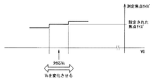
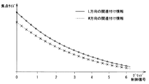
図9は、X線検出部14の分解能を考慮した焦点像51のサイズの測定方法の一例について説明するための図である。
FIG. 9 is a diagram for explaining an example of a method for measuring the size of the
X線検出部14を構成するX線検出素子のピッチをPmm、拡大率をMとすると、焦点サイズの分解能はP/Mmmとなる。焦点サイズに対してこの分解能が十分に高くない場合は、グリッド電圧VGを変化させながら焦点サイズの測定値の変化ポイントを探索するとよい。この場合、設定焦点サイズよりも大きくなるポイントおよび小さくなるポイントの中央値を設定グリッド電圧VSGとして記憶部17に記憶させるとよい。
When the pitch of the X-ray detection elements constituting the
ユーザは、よく用いる焦点サイズ(たとえば図8に示した大焦点、小焦点、極小焦点の3つなど)について第1の校正方法を実行することにより、よく用いる焦点サイズと正確な設定グリッド電圧VSGとを関連付けた情報を記憶部17に記憶させておくことができる。このため、第1の校正方法による校正後は、主制御部21は、この関連付けた情報を用いることにより、ユーザの所望の焦点サイズを容易に実現することができる。
The user performs the first calibration method for frequently used focus sizes (for example, three of the large focus, the small focus, and the minimum focus shown in FIG. 8), so that the frequently used focus size and the accurately set grid voltage VS are used. Information associated with G can be stored in the
この記憶部17に記憶させた設定グリッド電圧VSGW、VSGL(またはグリッド制御信号)と設定された焦点サイズとの関係は、X線管13の実特性およびグリッド制御部23の実特性の非線形要素を反映している。このため、第1の校正方法によれば、X線管13の実特性にばらつきがあっても、またグリッド制御部23のグリッド電圧の出力精度がそれほど高くなくても、X線管13の実特性およびグリッド制御部23の実特性を反映して焦点サイズを校正することができる。換言すれば、第1の校正方法による焦点サイズの校正方法においてX線管13の実特性およびグリッド制御部23の実特性は全く問題にならず、用いる必要もない。
The relationship between the set grid voltages VS GW and VS GL (or grid control signal) stored in the
また、X線管13の焦点サイズと実際の正確な設定グリッド電圧VSGとを関連付けた情報は、X線管13に固有の情報であり、X線管13が異なると標準特性情報も異なる。一方、第1の校正方法によれば、X線管13の実特性を反映した関連付け情報を得ることができる。このため、X線管13を交換した場合であっても、ユーザは、医用画像診断装置10により容易に交換後のX線管13についてのよく用いる焦点サイズと正確な設定グリッド電圧VSGとを関連付けた情報を得ることができる。
Information relating the focal size of the
次に、焦点サイズの第2の校正方法について説明する。第2の校正方法は、設定グリッド電圧を変更しつつ焦点サイズを求めることで設定グリッド電圧と焦点サイズとを関連付けた情報を生成することにより、焦点サイズとグリッド電圧との関係を校正し、ユーザの所望する設定焦点サイズを正確に実現する方法である。第2の校正方法は、標準特性情報を必要としない。 Next, the second calibration method for the focus size will be described. The second calibration method calibrates the relationship between the focus size and the grid voltage by generating information associating the set grid voltage with the focus size by obtaining the focus size while changing the set grid voltage, and This is a method for accurately realizing a desired set focal spot size. The second calibration method does not require standard characteristic information.
図10は、設定グリッド電圧を変更しつつ焦点サイズを求めることにより生成されるグリッド制御信号と焦点サイズとを関連付けた情報の一例を示す説明図である。図10にはグリッド制御信号と焦点サイズとを関連付けた情報の例を示したが、もちろん設定グリッド電圧と焦点サイズとを関連付けた情報を生成してもよい。 FIG. 10 is an explanatory diagram illustrating an example of information in which the grid control signal generated by obtaining the focus size while changing the set grid voltage and the focus size are associated with each other. FIG. 10 shows an example of information in which the grid control signal and the focus size are associated with each other. Of course, information in which the set grid voltage is associated with the focus size may be generated.
この設定グリッド電圧(またはグリッド制御信号)と焦点サイズとを関連付けた情報の生成処理は、たとえば操作コンソール11を介してユーザにより指示されて開始される。
The process of generating information in which the set grid voltage (or grid control signal) is associated with the focus size is started when instructed by the user via the
主制御部21はまず、設定グリッド電圧VSGW、VSGLの初期値VSstとしてたとえば0Vを設定し、この設定グリッド電圧VSGW、VSGLに対応するグリッド制御信号をグリッド制御部23に出力する。グリッド制御部23は、グリッド制御信号に応じてグリッド電圧VGW、VGLを生成し、X線管13のグリッド32に印加することによりX線管13の焦点サイズを制御する。主制御部21は、このグリッド電圧VGW、VGLでX線検出部14に結像された焦点像51のサイズから焦点サイズを求め、設定グリッド電圧VSGW、VSGL=0Vに関連付けて記憶部17に記憶させる。
The
次に、主制御部21は、設定グリッド電圧VSGW、VSGLを現在の値に所定の値−ΔV(たとえば−50V)を加えた電圧として同様に焦点サイズを求め、設定グリッド電圧VSGW、VSGL=0V−ΔVに関連付けて記憶部17に記憶させる。これを、設定グリッド電圧VSGW、VSGLがあらかじめ設定した終了値VSendになるまで繰り返す。この結果、主制御部21は、図10に示す設定グリッド電圧(またはグリッド制御信号)と焦点サイズとを関連付けた情報を生成することができる。
Next, the
この関連付けた情報の生成後は、主制御部21は、この関連付けた情報を用いることにより、ユーザの所望の焦点サイズを容易に実現することができる。また、第2の校正方法は、標準特性情報が必要ない。また、第1の校正方法のようにユーザのよく用いる焦点サイズに限られることなく任意の焦点サイズを正確に実現することができるため、たとえば焦点サイズを連続的に変化させる際にも正確な焦点サイズを実現することができる。
After the generation of the associated information, the
また、第2の校正方法により得られる関連付け情報もまた、第1の校正方法により得られる関連付け情報と同様に、X線管13の実特性およびグリッド制御部23の実特性の非線形要素を反映している。このため、第2の校正方法によっても、X線管13の実特性にばらつきがあっても、またグリッド制御部23のグリッド電圧の出力精度がそれほど高くなくても、X線管13の実特性およびグリッド制御部23の実特性を反映して焦点サイズを校正することができる。すなわち、第2の校正方法による焦点サイズの校正方法においても、X線管13の実特性およびグリッド制御部23の実特性は全く問題にならず、用いる必要もない。また、第2の校正方法によれば、X線管13を交換した場合、ユーザは、医用画像診断装置10により容易に交換後のX線管13の焦点サイズと正確な設定グリッド電圧VSGとを関連付けた情報を得ることができる。
In addition, the association information obtained by the second calibration method also reflects the non-linear elements of the actual characteristics of the
図11は、設定焦点サイズに対応する設定グリッド電圧VSGを求めることにより焦点サイズとグリッド電圧との関係を容易に校正する際の手順(第1の校正方法の手順)の一例を示すフローチャートである。図11において、Sに数字を付した符号はフローチャートの各ステップを示す。 Figure 11 is a flow chart showing an example of a procedure for easily calibrating the relationship between the focal spot size and the grid voltage by obtaining the setting grid voltage VS G corresponding to the set focus size (the procedure of the first calibration method) is there. In FIG. 11, a symbol with a number added to S indicates each step of the flowchart.
この手順は、あらかじめ記憶部17または主制御部21の記憶媒体に標準特性情報が記憶されてスタートとなる。
This procedure starts when standard characteristic information is stored in advance in the storage medium of the
まず、ステップS1において、主制御部21は、操作コンソール11から設定焦点サイズの情報を受ける。そして、主制御部21は、記憶部17に記憶された標準特性情報(図8参照)を用いて、この設定焦点サイズに関連付けられたグリッド電圧VGW、SGLの情報を取得し、このグリッド電圧VGW、VGLを設定グリッド電圧VSGW、VSGLとする。
First, in step S <b> 1, the
次に、ステップS2において、主制御部21は、設定グリッド電圧VSGW、VSGLに対応するグリッド制御信号をグリッド制御部23に出力する。グリッド制御部23は、グリッド制御信号に応じてグリッド電圧VGW、VGLを生成し、グリッド32に印加する。
Next, in step S <b> 2, the
次に、ステップS3において、X線管13は、X線光学部15を介してX線検出部14に焦点像51を結像する(図3参照)。
Next, in step S3, the
次に、ステップS4において、画像解析部16は、X線検出部14の出力にもとづいて焦点像51のW方向およびL方向のサイズを求めて主制御部21に与える。主制御部21は、焦点像51のサイズを拡大率Mで除すことにより、X線管13の焦点サイズを求める。なお、拡大率Mを周囲要素42の像にもとづいて拡大率Mを算出する方法(図6参照)や、X線光学部15の複数のマーカ72の像にもとづいて拡大率Mを算出する方法(図7参照)により求める場合には、このステップS4においてまず拡大率Mを求めて、求めた拡大率Mを用いて焦点サイズを求めてもよい。
Next, in step S <b> 4, the
次に、ステップS5において、求めた焦点サイズと設定焦点サイズとの差が閾値以内であるか否かを判定する。差が閾値より大きい場合は、ステップS6に進み、主制御部21は、この差を補正するように現在の設定グリッド電圧を変更し、変更後の設定グリッド電圧で再度焦点サイズを求めるようステップS2に戻る。
Next, in step S5, it is determined whether or not the difference between the obtained focus size and the set focus size is within a threshold value. When the difference is larger than the threshold value, the process proceeds to step S6, and the
一方、差が閾値以内の場合は、ステップS7において主制御部21は、現在の設定グリッド電圧VSGW、VSGLと設定焦点サイズとで、標準特性情報を更新するか、または標準特性情報とは別にこの実測した設定グリッド電圧VSGW、VSGLと設定された焦点サイズとの関係を記憶部17に記憶させる。
On the other hand, if the difference is within the threshold, in step S7, the
以上の手順により、設定焦点サイズに対応する設定グリッド電圧VSGを求めることにより焦点サイズとグリッド電圧との関係を容易に校正することができる。 By the above procedure, it is possible to calibrate the relationship between the focal spot size and the grid voltage easily by determining the set grid voltage VS G corresponding to the set focus size.
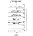
図12は、設定グリッド電圧を変更しつつ焦点サイズを求めることで設定グリッド電圧と焦点サイズとを関連付けた情報を生成することにより、焦点サイズとグリッド電圧との関係を校正する際の手順(第2の校正方法の手順)の一例を示すフローチャートである。 FIG. 12 shows a procedure for correcting the relationship between the focus size and the grid voltage by generating information associating the set grid voltage with the focus size by obtaining the focus size while changing the set grid voltage (first step). 2 is a flowchart showing an example of a procedure of the calibration method 2).
まず、ステップS11において、主制御部21は、設定グリッド電圧VSGW、VSGLの初期値VSst(たとえば0V)を設定する。
First, in step S11, the
次に、ステップS12において、主制御部21は、設定グリッド電圧VSGW、VSGLに対応するグリッド制御信号をグリッド制御部23に出力する。グリッド制御部23は、グリッド制御信号に応じてグリッド電圧VGW、VGLを生成し、グリッド32に印加する。
Next, in step S <b> 12, the
次に、ステップS13において、X線管13は、X線光学部15を介してX線検出部14に焦点像51を結像する(図3参照)。
Next, in step S13, the
次に、ステップS14において、画像解析部16は、X線検出部14の出力にもとづいて焦点像51のW方向およびL方向のサイズを求めて主制御部21に与える。主制御部21は、焦点像51のサイズを拡大率Mで除すことにより、X線管13の焦点サイズを求める。なお、拡大率Mを周囲要素42の像にもとづいて拡大率Mを算出する方法(図6参照)や、X線光学部15の複数のマーカ72の像にもとづいて拡大率Mを算出する方法(図7参照)により求める場合には、このステップS4においてまず拡大率Mを求めて、求めた拡大率Mを用いて焦点サイズを求めてもよい。
Next, in step S <b> 14, the
次に、ステップS15において、主制御部21は、求めた焦点サイズと現在の設定グリッド電圧VSGW、VSGLとを関連付けて記憶部17に記憶させる。
Next, in step S15, the
次に、ステップS16において、主制御部21は、設定グリッド電圧VSGW、VSGLを、現在の値に所定の値−ΔV(たとえば−50V)を加えた電圧に変更する。
Next, in step S16, the
次に、ステップS17において、主制御部21は、変更した設定グリッド電圧VSGW、VSGLがあらかじめ設定した終了値VSendより大きいか否かを判定する。終了値VSendより大きい場合は、一連の作業は終了となる。一方、終了値VSend以下である場合は、ステップS12に戻る。
Next, in step S17, the
以上の手順により、設定グリッド電圧を変更しつつ焦点サイズを求めることで設定グリッド電圧と焦点サイズとを関連付けた情報を生成することにより、焦点サイズとグリッド電圧との関係を校正することができる。 The relationship between the focus size and the grid voltage can be calibrated by generating information associating the set grid voltage and the focus size by obtaining the focus size while changing the set grid voltage by the above procedure.
本実施形態に係る医用画像診断装置10は、グリッド制御部23に与える設定グリッド電圧と焦点サイズとを関連付けた情報を得ることができる。この情報は、X線管13の実特性およびグリッド制御部23の実特性の非線形要素を反映している。このため、X線管13の実特性にばらつきがあっても、またグリッド制御部23のグリッド電圧の出力精度がそれほど高くなくても、X線管13の実特性およびグリッド制御部23の実特性を反映して焦点サイズを校正することができる。
The medical image
したがって、医用画像診断装置10によれば、X線管13やグリッド制御部23の特性が経年変化を起こした場合であっても、医用画像診断装置10の設置されている場所でユーザ自らが容易にX線管13の焦点サイズと正確な設定グリッド電圧VSGとを関連付けた情報を得ることができる。また、ユーザがX線管13を交換した場合や修理のためにグリッド制御部23を交換した場合であっても、同様に、医用画像診断装置10の設置されている場所でユーザ自らが容易に交換後のX線管13の焦点サイズと正確な設定グリッド電圧VSGとを関連付けた情報を得ることができる。また、定期点検でX線管13の焦点サイズと正確な設定グリッド電圧VSGとを関連付けた情報を得ることにより、常に正確な焦点サイズを実現することができる。
Therefore, according to the medical image
また、本実施形態に係る医用画像診断装置10の焦点サイズ校正方法によれば、X線管13やグリッド制御部23の特性を一切必要としない。このため、X線管13やグリッド制御部23の特性管理や保管管理に特別な配慮を要さない。
Further, according to the focus size calibration method of the medical image
なお、本発明のいくつかの実施形態を説明したが、これらの実施形態は、例として提示したものであり、発明の範囲を限定することは意図していない。これら新規な実施形態は、その他の様々な形態で実施されることが可能であり、発明の要旨を逸脱しない範囲で、種々の省略、置き換え、変更を行うことができる。これら実施形態やその変形は、発明の範囲や要旨に含まれるとともに、特許請求の範囲に記載された発明とその均等の範囲に含まれる。 In addition, although some embodiment of this invention was described, these embodiment is shown as an example and is not intending limiting the range of invention. These novel embodiments can be implemented in various other forms, and various omissions, replacements, and changes can be made without departing from the scope of the invention. These embodiments and modifications thereof are included in the scope and gist of the invention, and are included in the invention described in the claims and the equivalents thereof.
10 医用画像診断装置
13 X線管
14 X線検出部
15 X線光学部
16 画像解析部
17 記憶部
21 主制御部
23 グリッド制御部
32 グリッド
41 結像要素
42 周囲要素
43 基板
51 焦点像
52 焦点位置
61 寝台
62 床面
63 天板
64 支持部材
72 マーカ
DESCRIPTION OF
Claims (10)
このX線管と対向する位置に設けられたX線検出部と、
設定グリッド電圧に応じてグリッド電圧を生成し前記グリッドに印加するグリッド制御部と、
前記X線管と前記X線検出部との間に設置され、前記X線管の焦点像を前記X線検出部に結像させるX線光学部と、
前記X線管から照射されて前記X線光学部を介して前記X線検出部に結像された前記焦点像のサイズを出力する画像解析部と、
前記グリッド制御部に対して設定グリッド電圧を出力するとともに、出力した設定グリッド電圧に応じて結像された前記焦点像のサイズにもとづいて前記X線管の焦点サイズを求め、求めた焦点サイズと前記グリッド制御部に出力した設定グリッド電圧とを関連付けた情報を生成する主制御部と、
を備えた医用画像診断装置。 An X-ray tube having a grid, the focal spot size changing according to the grid voltage;
An X-ray detector provided at a position facing the X-ray tube;
A grid controller that generates a grid voltage according to a set grid voltage and applies the grid voltage to the grid;
An X-ray optical unit that is installed between the X-ray tube and the X-ray detection unit and forms a focal image of the X-ray tube on the X-ray detection unit;
An image analysis unit that outputs the size of the focus image irradiated from the X-ray tube and imaged on the X-ray detection unit via the X-ray optical unit;
A set grid voltage is output to the grid control unit, a focus size of the X-ray tube is obtained based on a size of the focus image formed in accordance with the output set grid voltage, and the obtained focus size A main control unit that generates information relating the set grid voltage output to the grid control unit;
A medical image diagnostic apparatus comprising:
をさらに備え、
前記主制御部は、
焦点サイズの設定情報を取得すると、この設定された焦点サイズに対応する設定グリッド電圧を前記記憶部から抽出して前記グリッド制御部に与え、前記X線管に前記X線光学部を介して前記X線検出部に前記焦点像を結像させることにより、前記記憶部から抽出した設定グリッド電圧に応じた前記X線管の焦点サイズを求め、求めた焦点サイズと前記設定された焦点サイズとの差が閾値以内になるように設定グリッド電圧を修正して再度前記X線管に前記X線光学部を介して前記X線検出部に前記焦点像を結像させて焦点サイズを求めることを繰り返し、前記閾値以内となった際の設定グリッド電圧と前記設定された焦点サイズとで、前記関連付けた情報を更新する、
請求項1記載の医用画像診断装置。 A storage unit that stores information that associates the focus size with the set grid voltage;
Further comprising
The main control unit
When the focus size setting information is acquired, a setting grid voltage corresponding to the set focus size is extracted from the storage unit and applied to the grid control unit, and the X-ray tube is connected to the X-ray optical unit via the X-ray optical unit. By forming the focus image on the X-ray detection unit, the focus size of the X-ray tube corresponding to the set grid voltage extracted from the storage unit is obtained, and the calculated focus size and the set focus size are obtained. The setting grid voltage is corrected so that the difference is within the threshold value, and the focus size is obtained again by forming the focus image on the X-ray detection unit via the X-ray optical unit on the X-ray tube again. , Updating the associated information with the set grid voltage and the set focus size when the value falls within the threshold value,
The medical image diagnostic apparatus according to claim 1.
前記グリッド制御部に与える設定グリッド電圧を変更しつつ焦点サイズを求めることを繰り返すことにより、複数の設定グリッド電圧のそれぞれと焦点サイズとの関係を生成することにより前記関連付けた情報を生成する、
請求項1または2に記載の医用画像診断装置。 The main control unit
Generating the associated information by generating a relationship between each of the plurality of setting grid voltages and the focus size by repeatedly obtaining the focus size while changing the set grid voltage applied to the grid control unit;
The medical image diagnostic apparatus according to claim 1 or 2.
前記X線管の焦点像を所定の倍率で前記X線検出部に結像させ、
前記主制御部は、
前記焦点像のサイズを前記所定の倍率で除すことにより前記焦点サイズを求める、
請求項1ないし3のいずれか1項に記載の医用画像診断装置。 The X-ray optical unit is
Forming a focused image of the X-ray tube on the X-ray detector at a predetermined magnification;
The main control unit
Obtaining the focal size by dividing the size of the focal image by the predetermined magnification;
The medical image diagnostic apparatus according to any one of claims 1 to 3.
前記天板に対して前記X線光学部を支持する支持部材と、
をさらに備えた請求項4記載の医用画像診断装置。 A couch having a top plate for placing the subject and placed on the floor;
A support member that supports the X-ray optical unit with respect to the top plate;
The medical image diagnostic apparatus according to claim 4, further comprising:
前記床面から前記天板の上面までの高さを制御することにより、前記天板の上面から前記支持部材に支持された前記X線光学部までの高さ、および前記X線管の焦点位置から前記X線検出部までの距離にもとづいて前記倍率を制御する、
請求項5記載の医用画像診断装置。 The main control unit
By controlling the height from the floor surface to the top surface of the top plate, the height from the top surface of the top plate to the X-ray optical unit supported by the support member, and the focal position of the X-ray tube The magnification is controlled based on the distance from the X-ray detection unit to
The medical image diagnostic apparatus according to claim 5.
前記画像解析部は、
前記X線検出部に結像された前記複数のマーカの像の間の距離を出力し、
前記主制御部は、
前記複数のX線マーカの前記X線光学部上での距離と、前記X線検出部に結像された前記複数のマーカの像の間の距離と、にもとづいて前記所定の倍率を求める、
請求項4ないし6のいずれか1項に記載の医用画像診断装置。 The X-ray optical unit has a plurality of X-ray markers,
The image analysis unit
Outputting the distance between the images of the plurality of markers imaged on the X-ray detector;
The main control unit
Obtaining the predetermined magnification based on the distance of the plurality of X-ray markers on the X-ray optical unit and the distance between the images of the plurality of markers imaged on the X-ray detection unit;
The medical image diagnostic apparatus according to any one of claims 4 to 6.
前記X線管の焦点像を結像するための結像要素と、この結像要素とは異なるX線透過率を有し前記結像要素を囲む周囲要素と、この周囲要素とは異なるX線透過率を有し前記周囲要素を支持する基板とを有し、
前記画像解析部は、
前記X線検出部に結像された前記周囲要素の像の輪郭サイズを出力し、
前記主制御部は、前記X線光学部上での前記周囲要素の輪郭サイズと、前記X線検出部に結像された前記周囲要素の像の輪郭サイズと、にもとづいて前記所定の倍率を求める、
請求項4ないし7のいずれか1項に記載の医用画像診断装置。 The X-ray optical unit is
An imaging element for forming a focal image of the X-ray tube, a surrounding element having an X-ray transmittance different from that of the imaging element and surrounding the imaging element, and an X-ray different from the surrounding element A substrate having a transmittance and supporting the surrounding elements;
The image analysis unit
Outputting the contour size of the image of the surrounding element imaged on the X-ray detector;
The main control unit calculates the predetermined magnification based on a contour size of the surrounding element on the X-ray optical unit and a contour size of the image of the surrounding element formed on the X-ray detection unit. Ask,
The medical image diagnostic apparatus according to any one of claims 4 to 7.
ピンホールカメラ法を適用するためのピンホールにより構成される、
請求項1ないし8のいずれか1項に記載の医用画像診断装置。 The X-ray optical unit is
Consists of pinholes for applying the pinhole camera method,
The medical image diagnostic apparatus according to any one of claims 1 to 8.
焦点サイズがグリッド電圧に応じて変化するX線管のグリッドに対して、前記グリッド制御部が生成したグリッド電圧を印加するステップと、
前記X線管と、このX線管と対向する位置に設けられたX線検出部と、の間に設置されたX線光学部により、前記X線管の焦点像が前記X線検出部に結像するステップと、
前記焦点像のサイズにもとづいて前記X線管の焦点サイズを求めるステップと、
求めた焦点サイズと前記グリッド制御部に入力された設定グリッド電圧とを関連付けた情報を生成するステップと、
を有する焦点サイズ校正方法。 A step in which the grid control unit generates a grid voltage according to the input set grid voltage;
Applying a grid voltage generated by the grid control unit to an X-ray tube grid whose focal spot size changes according to the grid voltage;
An X-ray optical unit installed between the X-ray tube and an X-ray detection unit provided at a position facing the X-ray tube causes a focus image of the X-ray tube to be transferred to the X-ray detection unit. Imaging step;
Determining a focus size of the X-ray tube based on a size of the focus image;
Generating information associating the determined focus size with the set grid voltage input to the grid control unit;
A focus size calibration method.
Priority Applications (1)
| Application Number | Priority Date | Filing Date | Title |
|---|---|---|---|
| JP2013211714A JP6381884B2 (en) | 2013-10-09 | 2013-10-09 | Medical diagnostic imaging apparatus and focus size calibration method |
Applications Claiming Priority (1)
| Application Number | Priority Date | Filing Date | Title |
|---|---|---|---|
| JP2013211714A JP6381884B2 (en) | 2013-10-09 | 2013-10-09 | Medical diagnostic imaging apparatus and focus size calibration method |
Publications (2)
| Publication Number | Publication Date |
|---|---|
| JP2015073725A true JP2015073725A (en) | 2015-04-20 |
| JP6381884B2 JP6381884B2 (en) | 2018-08-29 |
Family
ID=52999054
Family Applications (1)
| Application Number | Title | Priority Date | Filing Date |
|---|---|---|---|
| JP2013211714A Active JP6381884B2 (en) | 2013-10-09 | 2013-10-09 | Medical diagnostic imaging apparatus and focus size calibration method |
Country Status (1)
| Country | Link |
|---|---|
| JP (1) | JP6381884B2 (en) |
Cited By (4)
| Publication number | Priority date | Publication date | Assignee | Title |
|---|---|---|---|---|
| US10019795B2 (en) | 2016-08-15 | 2018-07-10 | The Research Foundation For The State University Of New York | Focal spot de-blurring |
| JP2018129126A (en) * | 2017-02-06 | 2018-08-16 | キヤノンメディカルシステムズ株式会社 | X-ray imaging device |
| JP2019118699A (en) * | 2018-01-10 | 2019-07-22 | キヤノンメディカルシステムズ株式会社 | X-ray diagnostic apparatus |
| JP2024066454A (en) * | 2022-10-31 | 2024-05-15 | ジーイー・プレシジョン・ヘルスケア・エルエルシー | Systems and methods for computed tomography - Patents.com |
Citations (8)
| Publication number | Priority date | Publication date | Assignee | Title |
|---|---|---|---|---|
| JPH02267894A (en) * | 1989-04-10 | 1990-11-01 | Toshiba Corp | Focus compensation device for x-ray generator |
| JPH08242401A (en) * | 1994-12-14 | 1996-09-17 | Soc Natl Etud Constr Mot Aviat <Snecma> | Measuring method for size of optical focus of radioactive ray generating tube |
| JP2001299733A (en) * | 2000-04-27 | 2001-10-30 | Konica Corp | Pci radiation beam image processing apparatus, pci radiation beam image detecting and processing apparatus, pci radiation beam image outputting apparatus and pci radiation beam image diagnosis supporting apparatus |
| JP2006164819A (en) * | 2004-12-09 | 2006-06-22 | Hitachi Medical Corp | Microfocus x-ray tube and x-ray device using it |
| JP2010075317A (en) * | 2008-09-25 | 2010-04-08 | Fujifilm Corp | Stereo biopsy apparatus, method for controlling the same and phantom |
| WO2010060007A1 (en) * | 2008-11-24 | 2010-05-27 | Hologic Inc. | Method and system for controlling x-ray focal spot characteristics for tomosynthesis and mammography imaging |
| JP2011005018A (en) * | 2009-06-26 | 2011-01-13 | Ge Medical Systems Global Technology Co Llc | X-ray ct apparatus |
| JP2012138168A (en) * | 2010-02-23 | 2012-07-19 | Canon Inc | Radiation generator and radiation imaging system |
-
2013
- 2013-10-09 JP JP2013211714A patent/JP6381884B2/en active Active
Patent Citations (8)
| Publication number | Priority date | Publication date | Assignee | Title |
|---|---|---|---|---|
| JPH02267894A (en) * | 1989-04-10 | 1990-11-01 | Toshiba Corp | Focus compensation device for x-ray generator |
| JPH08242401A (en) * | 1994-12-14 | 1996-09-17 | Soc Natl Etud Constr Mot Aviat <Snecma> | Measuring method for size of optical focus of radioactive ray generating tube |
| JP2001299733A (en) * | 2000-04-27 | 2001-10-30 | Konica Corp | Pci radiation beam image processing apparatus, pci radiation beam image detecting and processing apparatus, pci radiation beam image outputting apparatus and pci radiation beam image diagnosis supporting apparatus |
| JP2006164819A (en) * | 2004-12-09 | 2006-06-22 | Hitachi Medical Corp | Microfocus x-ray tube and x-ray device using it |
| JP2010075317A (en) * | 2008-09-25 | 2010-04-08 | Fujifilm Corp | Stereo biopsy apparatus, method for controlling the same and phantom |
| WO2010060007A1 (en) * | 2008-11-24 | 2010-05-27 | Hologic Inc. | Method and system for controlling x-ray focal spot characteristics for tomosynthesis and mammography imaging |
| JP2011005018A (en) * | 2009-06-26 | 2011-01-13 | Ge Medical Systems Global Technology Co Llc | X-ray ct apparatus |
| JP2012138168A (en) * | 2010-02-23 | 2012-07-19 | Canon Inc | Radiation generator and radiation imaging system |
Cited By (4)
| Publication number | Priority date | Publication date | Assignee | Title |
|---|---|---|---|---|
| US10019795B2 (en) | 2016-08-15 | 2018-07-10 | The Research Foundation For The State University Of New York | Focal spot de-blurring |
| JP2018129126A (en) * | 2017-02-06 | 2018-08-16 | キヤノンメディカルシステムズ株式会社 | X-ray imaging device |
| JP2019118699A (en) * | 2018-01-10 | 2019-07-22 | キヤノンメディカルシステムズ株式会社 | X-ray diagnostic apparatus |
| JP2024066454A (en) * | 2022-10-31 | 2024-05-15 | ジーイー・プレシジョン・ヘルスケア・エルエルシー | Systems and methods for computed tomography - Patents.com |
Also Published As
| Publication number | Publication date |
|---|---|
| JP6381884B2 (en) | 2018-08-29 |
Similar Documents
| Publication | Publication Date | Title |
|---|---|---|
| JP6381884B2 (en) | Medical diagnostic imaging apparatus and focus size calibration method | |
| JP2015536551A (en) | Dynamically adjustable filament control via firmware for small X-ray sources | |
| JPWO2019151251A1 (en) | X-ray tube control method and X-ray tube control device | |
| CN112912987B (en) | X-ray generating device and X-ray imaging system | |
| CN115165932B (en) | An X-ray non-destructive testing device, a pixel size calibration method, and a storage medium. | |
| JP4464857B2 (en) | Charged particle beam equipment | |
| JP2017187352A (en) | X-ray residual stress measurement method and X-ray residual stress measurement system | |
| JP2006164819A (en) | Microfocus x-ray tube and x-ray device using it | |
| JP2015116408A (en) | X-ray ct apparatus and defective element correction method | |
| KR101552318B1 (en) | X-ray generation apparatus, computerized tomography system having the same and method for control thereof | |
| JPH05329143A (en) | Ct scanner | |
| US20260101427A1 (en) | Systems and methods for adaptively controlling filament current in an x-ray tube | |
| JP4699167B2 (en) | X-ray diagnostic imaging equipment | |
| US9829447B2 (en) | X-ray fluorescence analyzer and method of displaying sample thereof | |
| JP2008218338A (en) | X-ray generator, X-ray computed tomography apparatus and X-ray diagnostic apparatus | |
| JP6257929B2 (en) | X-ray computed tomography system | |
| JP2011182974A (en) | Controller for radiation source, radiographic system, and method for updating exposure conditions | |
| US7425702B2 (en) | Charged particle beam apparatus | |
| US12376217B2 (en) | X-ray diagnostic apparatus | |
| EP4425158A1 (en) | X-ray analysis apparatus and method | |
| CN1669527B (en) | Methods and systems for calibrating medical imaging devices | |
| JP6099938B2 (en) | Multi X-ray generator tube and X-ray imaging system using the same | |
| JP3904021B2 (en) | Electron beam analysis method | |
| JP5604965B2 (en) | Radioscopic imaging equipment | |
| JP2025115792A (en) | X-ray imaging device and method for adjusting current supplied to filament |
Legal Events
| Date | Code | Title | Description |
|---|---|---|---|
| A711 | Notification of change in applicant |
Free format text: JAPANESE INTERMEDIATE CODE: A711 Effective date: 20160511 |
|
| A621 | Written request for application examination |
Free format text: JAPANESE INTERMEDIATE CODE: A621 Effective date: 20160804 |
|
| A977 | Report on retrieval |
Free format text: JAPANESE INTERMEDIATE CODE: A971007 Effective date: 20170731 |
|
| A131 | Notification of reasons for refusal |
Free format text: JAPANESE INTERMEDIATE CODE: A131 Effective date: 20170829 |
|
| A521 | Request for written amendment filed |
Free format text: JAPANESE INTERMEDIATE CODE: A523 Effective date: 20170927 |
|
| A131 | Notification of reasons for refusal |
Free format text: JAPANESE INTERMEDIATE CODE: A131 Effective date: 20180306 |
|
| A521 | Request for written amendment filed |
Free format text: JAPANESE INTERMEDIATE CODE: A523 Effective date: 20180425 |
|
| TRDD | Decision of grant or rejection written | ||
| A01 | Written decision to grant a patent or to grant a registration (utility model) |
Free format text: JAPANESE INTERMEDIATE CODE: A01 Effective date: 20180703 |
|
| A61 | First payment of annual fees (during grant procedure) |
Free format text: JAPANESE INTERMEDIATE CODE: A61 Effective date: 20180801 |
|
| R150 | Certificate of patent or registration of utility model |
Ref document number: 6381884 Country of ref document: JP Free format text: JAPANESE INTERMEDIATE CODE: R150 |