JP2015073700A - Automatic disassembling apparatus of game machine - Google Patents
Automatic disassembling apparatus of game machine Download PDFInfo
- Publication number
- JP2015073700A JP2015073700A JP2013211315A JP2013211315A JP2015073700A JP 2015073700 A JP2015073700 A JP 2015073700A JP 2013211315 A JP2013211315 A JP 2013211315A JP 2013211315 A JP2013211315 A JP 2013211315A JP 2015073700 A JP2015073700 A JP 2015073700A
- Authority
- JP
- Japan
- Prior art keywords
- gaming machine
- automatic
- screw loosening
- main body
- screw
- Prior art date
- Legal status (The legal status is an assumption and is not a legal conclusion. Google has not performed a legal analysis and makes no representation as to the accuracy of the status listed.)
- Granted
Links
- 230000007246 mechanism Effects 0.000 claims abstract description 145
- 238000005520 cutting process Methods 0.000 claims description 73
- 238000012545 processing Methods 0.000 claims description 58
- 238000000034 method Methods 0.000 claims description 54
- WABPQHHGFIMREM-UHFFFAOYSA-N lead(0) Chemical compound [Pb] WABPQHHGFIMREM-UHFFFAOYSA-N 0.000 claims description 53
- 230000008569 process Effects 0.000 claims description 52
- 238000001179 sorption measurement Methods 0.000 claims description 7
- 238000011084 recovery Methods 0.000 claims 1
- 230000008859 change Effects 0.000 abstract description 6
- 230000000694 effects Effects 0.000 description 31
- 210000000078 claw Anatomy 0.000 description 11
- 238000013459 approach Methods 0.000 description 5
- XEEYBQQBJWHFJM-UHFFFAOYSA-N Iron Chemical group [Fe] XEEYBQQBJWHFJM-UHFFFAOYSA-N 0.000 description 4
- 239000000463 material Substances 0.000 description 4
- 239000002344 surface layer Substances 0.000 description 4
- 238000000605 extraction Methods 0.000 description 3
- 239000011521 glass Substances 0.000 description 3
- 238000002360 preparation method Methods 0.000 description 3
- 206010034719 Personality change Diseases 0.000 description 2
- 229910052774 Proactinium Inorganic materials 0.000 description 2
- FFBHFFJDDLITSX-UHFFFAOYSA-N benzyl N-[2-hydroxy-4-(3-oxomorpholin-4-yl)phenyl]carbamate Chemical compound OC1=C(NC(=O)OCC2=CC=CC=C2)C=CC(=C1)N1CCOCC1=O FFBHFFJDDLITSX-UHFFFAOYSA-N 0.000 description 2
- 238000009434 installation Methods 0.000 description 2
- 239000010410 layer Substances 0.000 description 2
- 229910052745 lead Inorganic materials 0.000 description 2
- 239000004973 liquid crystal related substance Substances 0.000 description 2
- 238000004519 manufacturing process Methods 0.000 description 2
- 239000002184 metal Substances 0.000 description 2
- 229910052751 metal Inorganic materials 0.000 description 2
- 230000004048 modification Effects 0.000 description 2
- 238000012986 modification Methods 0.000 description 2
- 230000001681 protective effect Effects 0.000 description 2
- 238000004064 recycling Methods 0.000 description 2
- 239000002023 wood Substances 0.000 description 2
- 241000722921 Tulipa gesneriana Species 0.000 description 1
- 230000001174 ascending effect Effects 0.000 description 1
- 239000011248 coating agent Substances 0.000 description 1
- 238000000576 coating method Methods 0.000 description 1
- 239000002131 composite material Substances 0.000 description 1
- 238000005516 engineering process Methods 0.000 description 1
- 230000008676 import Effects 0.000 description 1
- 238000011068 loading method Methods 0.000 description 1
- 238000002156 mixing Methods 0.000 description 1
- 239000002994 raw material Substances 0.000 description 1
- 239000011347 resin Substances 0.000 description 1
- 229920005989 resin Polymers 0.000 description 1
- 238000011144 upstream manufacturing Methods 0.000 description 1
- 239000002699 waste material Substances 0.000 description 1
Images
Landscapes
- Pinball Game Machines (AREA)
Abstract
Description
本発明は、パチンコ台およびスロット台等の遊技機に取り付けられている部品を自動的に取り外すことができる遊技機の自動解体処理装置に関する。 The present invention relates to an automatic dismantling apparatus for a gaming machine that can automatically remove parts attached to the gaming machine such as a pachinko machine and a slot machine.
パチンコ台(パチンコ遊技機)およびスロット台(回胴式遊技機)等の遊技機は、プラスチックや木で形成される遊技盤、枠、扉体、筐体等の本体部に対し、金属、プラスチック、ガラス、木材等の異なる材料で形成される多種多様の構成部品を取り付けてなる。各材料については、既に再生・再利用技術が確立されているため、使用済みの遊技機をそのまま埋め立てて廃棄処分することは、資源の無駄遣いになり、地球環境にも重大な影響を与える。 Game machines such as pachinko machines (pachinko machines) and slot machines (rotating-type game machines) are made of metal or plastic against the main body parts such as game boards, frames, doors, and cases made of plastic or wood. A wide variety of components made of different materials such as glass and wood are attached. Since recycling and reuse technologies have already been established for each material, it is a waste of resources to dispose of used amusement machines as they are and has a significant impact on the global environment.
そこで、遊技機を分解して各構成部品を取り外し、材料別に細かく分別したうえで、新たな原材料として再資源化したり、焼却して熱エネルギーを回収したりするアイデアが提案されている(例えば、特許文献1参照。)。遊技機から構成部品を自動的に取り外す手段としては、例えば本件出願人が、パチンコ台に打設された遊技釘を、櫛状の釘抜歯を付けた回転刃で連続的に引き抜く釘抜装置を提案済みである(例えば、特許文献2参照。)。 Therefore, the idea of disassembling the gaming machine, removing each component and separating it finely by material, recycling it as a new raw material, or recovering thermal energy by incineration has been proposed (for example, (See Patent Document 1). As a means for automatically removing components from gaming machines, for example, the applicant of the present application proposes a nail extraction device that continuously pulls out game nails placed on a pachinko machine with a rotary blade with comb-like nail extraction teeth. (For example, refer to Patent Document 2).
遊技機に取り付けられる構成部品は、遊技釘のほかに、例えば、装飾カバー、風車・チューリップ・アタッカー等の役物、照明ユニット、音響ユニット、液晶表示モニター等の画像表示装置、遊技球の流路ユニット、センサユニット、遊技球タンク、賞球払出装置、制御基板ユニット、電源ユニット、端子盤、ユニット保護カバー等がある。これらの取り付け部品は遊技釘と異なり、様々な大きさや形状に形成されており、取り付けネジで固定されていたり、コネクタ付リード線で相互に接続されていたりする。 In addition to game nails, the components attached to the gaming machine include, for example, decorative covers, windmills, tulips, attackers, and other objects, lighting units, acoustic units, image display devices such as liquid crystal display monitors, and flow paths for game balls. There are units, sensor units, game ball tanks, prize ball payout devices, control board units, power supply units, terminal boards, unit protective covers, and the like. Unlike game nails, these attachment parts are formed in various sizes and shapes, and are fixed with attachment screws or connected to each other with lead wires with connectors.
しかも、多数の構成部品が、何層にも重ね合わされた状態で複雑に取り付けられ、更に部品固定用ネジの頭部がリード線で覆われていることがある。そのため、予めリード線を切除しなければ取り付けネジを緩められず、また、表面を覆う部品を取り除かなければ奥にある部品の取り付けネジを緩められないなど、複数段階に分けて解体する必要がある。また、表面を覆う部品とその奥にある部品が相互に絡み合っていたり、枠や筐体等に形成された凹部等に部品が嵌まり込んでいたりして、スムーズに取り外せないこともある。 In addition, a large number of component parts may be attached in a complicated manner in a state where they are stacked in layers, and the heads of the component fixing screws may be covered with lead wires. Therefore, it is necessary to disassemble in several stages, such as the attachment screw cannot be loosened unless the lead wire is cut in advance, and the attachment screw of the inner part cannot be loosened unless the part covering the surface is removed. . In addition, a part covering the surface and a part in the back may be entangled with each other, or the part may be fitted in a recess formed in a frame, a housing, or the like, and may not be removed smoothly.
しかも取り付けネジの箇所の位置や数は、遊技機の機種や部品によって異なり、ネジの頭部は一般に部品表面より奥まった位置にあるため、遊技釘のように回転刃で連続的に引っ掛けるような取り外し方法は採用できない。ネジの向きも遊技機の枠や筐体等の壁面に対して垂直ではなく、斜め向きになっている場合もあり、その角度も様々である。 In addition, the location and number of mounting screws vary depending on the model and parts of the gaming machine, and since the head of the screw is generally located behind the surface of the part, it may be hooked continuously with a rotary blade like a game nail. The removal method cannot be adopted. The direction of the screw is not perpendicular to the wall surface of the gaming machine frame or the case, but may be inclined, and the angle is various.
すなわち、遊技機の解体処理は、まず構成部品同士を接続するリード線を切断し、部品固定用ネジを緩めて表面を覆う部品を取り除く。次にその直下に現れる別のネジを緩めて部品を取り除き、更にその奥に現れる部品を取り除くといった煩雑な作業を繰り返し行う必要がある。そのため、上述した遊技釘の引き抜きなどの一部の作業を除き、現状では、人手作業に頼っているが、人件費によるコスト負担は大きく、なかなか採算が合わないという問題がある。これに対して、一時に解体処理を行う遊技機の機種を揃えるなど、処理内容を一定化して効率を上げる工夫がなされているが、最近の遊技機は高機能化により部品点数が大幅に増えており、それに応じて作業項目も非常に多くなっているため、短時間で処理することは難しく、すべての使用済み遊技機を適切に解体し、有効なリサイクルを行うことは物理的に困難となっている。 That is, in the disassembling process of the gaming machine, first, the lead wire connecting the component parts is cut, and the part fixing screw is loosened to remove the part covering the surface. Next, it is necessary to repeatedly perform complicated operations such as loosening another screw appearing immediately below to remove the component, and further removing the component appearing behind the screw. For this reason, except for some operations such as the extraction of the game nails described above, currently, it relies on manual operations, but there is a problem that the cost burden due to personnel costs is large and it is difficult to make a profit. On the other hand, devices have been devised to increase the efficiency by making the content of processing constant, such as aligning the types of gaming machines that perform dismantling processing at a time, but the number of parts has greatly increased due to the higher functionality of recent gaming machines Therefore, it is difficult to process in a short time, and it is physically difficult to dismantle all used gaming machines properly and effectively recycle them. It has become.
本発明は、上記のような事情に鑑みて、多種多様な構成部品が取り付けられている遊技機について、自動的に、短時間でかつ効率的に解体処理することを目的とする。 In view of the circumstances as described above, an object of the present invention is to automatically and efficiently dismantle a gaming machine to which a wide variety of components are attached in a short time.
本願請求項1の発明は、所定姿勢にセットされた遊技機本体部に固定されている部品の取り付けネジを緩めるネジ緩め機構と、前記ネジ緩め機構で取り付けネジを緩めた部品を下方に落とすように遊技機本体部の姿勢を変更する姿勢変更機構を備えることを特徴とする遊技機の自動解体処理装置を提供する。ここで、本願請求項における「遊技機本体部」とは、パチンコ台(パチンコ遊技機)の遊技盤又は枠あるいはスロット台(回胴式遊技機)の前扉体又は筐体等、遊技機を構成する枠状・パネル状・トレイ状又は箱状の構造体で、種々の構成部品が取り付けられるものを意味する。また、パチンコ台の「枠」には、遊技機島に設置される外枠、外枠に対して開閉可能に収納される本体枠、本体枠前面に開閉可能に設けられるガラス扉枠及びこれらの枠を構成する枠状・パネル状・トレイ状又は箱状の構造体で、種々の構成部品が取り付けられるものを含むものとする。 According to the first aspect of the present invention, a screw loosening mechanism for loosening a mounting screw of a part fixed to a gaming machine main body set in a predetermined posture, and a part for which the mounting screw is loosened by the screw loosening mechanism is dropped downward. An automatic disassembly processing device for a gaming machine is provided that includes a posture changing mechanism for changing the posture of the gaming machine main body. Here, the “game machine main body” in the claims of the present application refers to a game machine such as a game board or frame of a pachinko machine (pachinko game machine) or a front door body or a case of a slot machine (rotating game machine). This means a frame-like, panel-like, tray-like or box-like structure to which various components are attached. In addition, the “frame” of the pachinko machine includes an outer frame installed on the gaming machine island, a main body frame that can be opened and closed with respect to the outer frame, a glass door frame that can be opened and closed on the front surface of the main body frame, and these A frame-like, panel-like, tray-like or box-like structure constituting the frame, including one to which various components are attached.
本願請求項2の発明は、前記ネジ緩め機構が、所定姿勢にセットされた遊技機本体部における上向きの部品取り付け面に固定されている部品の取り付けネジを緩めて、前記姿勢変更機構が、前記上向きの部品取り付け面を下方へ向けるように遊技機本体部を上下反転させることを特徴とする請求項1記載の遊技機の自動解体処理装置を提供する。
In the invention of
本願請求項3の発明は、前記ネジ緩め機構が、所定姿勢にセットされた枠状、トレイ状又は箱状の遊技機本体部において上向きに開かれた開口部の内側に固定されている部品の取り付けネジを緩めて、前記姿勢変更機構が、前記上向きの開口部を下方へ向けるように遊技機本体部を上下反転させることを特徴とする請求項1又は2記載の遊技機の自動解体処理装置を提供する。
The invention of
本願請求項4の発明は、前記ネジ緩め機構により固定されている部品の取り付けネジを緩めて、前記姿勢変更機構により部品を落とすように遊技機本体部の姿勢を変更する一連の工程を、一台の遊技機本体部に対して複数回繰り返すことを特徴とする請求項1乃至3のいずれかに記載の遊技機の自動解体処理装置を提供する。
The invention of
本願請求項5の発明は、異なる複数の部品取り付け面を有する遊技機本体部から部品を取り外す場合において、前記ネジ緩め機構がいずれかの部品取り付け面に固定されている部品の取り付けネジを緩めた後、前記姿勢変更機構が取り付けネジを緩めた部品を下方に落とすように遊技機本体部の姿勢を変更した際に、前記ネジ緩め機構が他の部品取り付け面に固定されている部品の取り付けネジを緩めることを特徴とする請求項4記載の遊技機の自動解体処理装置を提供する。
In the invention of
本願請求項6の発明は、前記ネジ緩め機構によるネジ緩め処理を行う前に、ネジ緩め処理の対象となる部品に接続されているリード線を切断するリード線切断機構を備えることを特徴とする請求項1乃至5のいずれかに記載の遊技機の自動解体処理装置を提供する。
The invention of
本願請求項7の発明は、前記リード線切断機構は、対となる刃物を開閉させる自動切断工具を備えてなり、前記自動切断工具は、鋏んだリード線を刃物に巻き付ける方向に自転することを特徴とする請求項6記載の遊技機の自動解体処理装置を提供する。
In the invention of claim 7 of the present application, the lead wire cutting mechanism includes an automatic cutting tool that opens and closes a pair of cutting tools, and the automatic cutting tool rotates in a direction to wind a staggered lead wire around the cutting tool. An automatic dismantling apparatus for a gaming machine according to
本願請求項8の発明は、前記ネジ緩め機構は、ロボットアームに装着される第1の自動ネジ緩め工具と、長手方向と直交する方向にスライド可能に設けられるレールにスライド可能に支持されることによりネジ緩め処理の対象となるネジに相対向する位置までスライド移動する第2の自動ネジ緩め工具を備えることを特徴とする請求項1乃至7のいずれかに記載の遊技機の自動解体処理装置を提供する。
In the invention of
本願請求項9の発明は、ロボットアームに前記自動切断工具と前記第1の自動ネジ緩め工具を取り替え可能に装着することを特徴とする請求項8記載の遊技機の自動解体処理装置を提供する。
The invention according to claim 9 of the present application provides the automatic dismantling processing apparatus for a gaming machine according to
本願請求項10の発明は、遊技機本体部の姿勢を変更して部品を落下させる際に遊技機本体部に振動を与える振動機構を備えることを特徴とする請求項1乃至9のいずれかに記載の遊技機の自動解体処理装置を提供する。 The invention of claim 10 of the present application is provided with a vibration mechanism that vibrates the gaming machine main body when changing the posture of the gaming machine main body and dropping the component. Provided is an automatic dismantling apparatus for the described gaming machine.
本願請求項11の発明は、遊技機本体部の姿勢を変更して部品を落下させる際に遊技機本体部に衝撃力を加える衝撃機構を備えることを特徴とする請求項1乃至10のいずれかに記載の遊技機の自動解体処理装置を提供する。 The invention of claim 11 of the present application is provided with an impact mechanism that applies an impact force to the game machine main body when the posture of the game machine main body is changed to drop a component. The automatic dismantling processing apparatus for gaming machines described in 1. is provided.
本願請求項12の発明は、前記ネジ緩め機構によるネジ緩め処理を行った後、前記姿勢変更機構による遊技機本体部の姿勢変更を行う前に、ネジ緩め処理が行われた部品のうち所定の部品を保持して回収する保持回収機構を備えることを特徴とする請求項1乃至11のいずれかに記載の遊技機の自動解体処理装置を提供する。
In the invention of claim 12 of the present application, after performing the screw loosening process by the screw loosening mechanism, before performing the attitude change of the gaming machine main body by the attitude changing mechanism, the predetermined part among the parts subjected to the screw loosening process The automatic dismantling processing apparatus for a gaming machine according to any one of
本願請求項13の発明は、部品を落とす遊技機本体部の下方位置から横方向に延びるように設けられ、遊技機本体部から落下させられる部品を受けて連続的に搬送するベルトコンベアを備えることを特徴とする請求項1乃至12のいずれかに記載の遊技機の自動解体処理装置を提供する。
The invention of claim 13 of the present application is provided with a belt conveyor which is provided so as to extend laterally from a lower position of the gaming machine main body part where the parts are dropped and continuously receives the parts dropped from the gaming machine main body part. An automatic dismantling apparatus for a gaming machine according to any one of
本願請求項14の発明は、前記ベルトコンベアにおいて部品が落下する前記下方位置より下流側で、かつ前記ベルトコンベアの上方側に磁力吸着機構を備えることを特徴とする請求項13記載の遊技機の自動解体処理装置を提供する。 14. The game machine according to claim 13, further comprising a magnetic force adsorption mechanism on the downstream side of the lower position where the parts fall on the belt conveyor and on the upper side of the belt conveyor. An automatic dismantling apparatus is provided.
本願請求項15の発明は、遊技機本体部から部品を下方に落下させる工程がすべて終了した後に、遊技機本体部を落下させることを特徴とする請求項1乃至14のいずれかに記載の遊技機の自動解体処理装置を提供する。 The invention according to claim 15 is characterized in that the gaming machine main body is dropped after all the steps of dropping the parts from the gaming machine main body are completed. An automatic dismantling device for a machine is provided.
本願請求項1の発明によれば、以下の優れた効果を奏し得る。遊技機本体部に固定された部品の取り付けネジを緩め、遊技機本体部の姿勢を変更してネジを緩めた部品の取り付け面を傾斜させて、あるいは当該取り付け面を横向き又は下向きにすることにより、ネジを緩めた部品や緩めたネジを一度に落下させてすべて取り除けるので、チャッキング装置等で各部品を個別に保持して取り除く場合に比べて処理時間が大幅に短縮される。 According to the first aspect of the present invention, the following excellent effects can be obtained. Loosen the mounting screws of the parts fixed to the gaming machine main unit, change the posture of the gaming machine main unit and tilt the mounting surface of the loosened parts, or make the mounting surface sideways or downward Since the loosened parts and the loosened screws can be dropped and removed all at once, the processing time can be greatly shortened compared with the case where each part is held and removed individually by a chucking device or the like.
本願請求項2の発明によれば、本願請求項1の発明が奏し得る効果に加えて、以下の優れた効果を奏し得る。上向きにした部品取り付け面のネジを緩めるので、ネジ緩め処理の途中に部品が大きくずれ動いたり、部品がネジ緩め機構の上に落ちたりする事態が防止される。また、ネジを緩めた部品取り付け面を下方に向けるので、ネジを緩めた部品を確実に落下させて取り除くことができる。
According to the invention of
本願請求項3の発明によれば、本願請求項1又は2の発明が奏し得る効果に加えて、以下の優れた効果を奏し得る。上向きに開いた開口部の内側にある部品の取り付けネジを緩めるので、ネジ緩め処理の途中に部品が不意に落ちたり、部品がネジ緩め機構の上に落ちたりする事態が防止される。また、その開口部を下方に向けるので、ネジを緩めた部品を確実に落下させて取り除くことができる。
According to the invention of
本願請求項4の発明によれば、本願請求項1乃至3の発明が奏し得る効果に加えて、以下の優れた効果を奏し得る。部品の取り付けネジを緩めて落下させるという一連の工程を一台の遊技機本体部に対して複数回繰り返すことにより、部品を複数層積み重ねるように複雑に取り付けている(例えば表面を覆う部品を取り除かなければ、奥の部品を取り除けない)場合や、遊技機本体部の表面と裏面(あるいは外側面と内側面)などの複数面にそれぞれ部品を取り付けている場合でも、一度装置に投入すれば解体処理を完全に済ませられ、結果としてトータル処理時間を大幅に短縮できる。
According to the invention of
本願請求項5の発明によれば、本願請求項4の発明が奏し得る効果に加えて、以下の優れた効果を奏し得る。異なる複数の部品取り付け面を有する遊技機本体部について、ある部品取り付け面(例えば表面あるいは内側面)から部品を落とすために姿勢を変化させたときに、その姿勢のままで他の部品取り付け面(例えば裏面あるいは外側面)のネジ緩め処理を行うので、異なる複数の部品取り付け面を連続的に解体処理することができ、結果としてトータル処理時間が一層短縮される。
According to the invention of
本願請求項6の発明によれば、本願請求項1乃至5の発明が奏し得る効果に加えて、以下の優れた効果を奏し得る。ネジ緩め処理前にリード線を切断するので、ネジ緩め処理がリード線により阻害される事態が防止される。また、ネジ緩め処理前は部品が固定されているため、リード線が切断処理中に動くことなく確実に切断できる。
According to the invention of
本願請求項7の発明によれば、本願請求項6の発明が奏し得る効果に加えて、以下の優れた効果を奏し得る。対となる刃物を開閉させる自動切断工具を採用したので、リード線を確実に捉えることができる。また、リード線を鋏んだ状態で刃物に巻き付けるように自転することで、引っ張られたリード線が刃部に強く当てられて確実に切断される。
According to the invention of claim 7 of the present application, in addition to the effect that the invention of
本願請求項8の発明によれば、本願請求項1乃至7の発明が奏し得る効果に加えて、以下の優れた効果を奏し得る。ロボットアームに装着される第1の自動ネジ緩め工具と、直交する2方向にスライド移動する第2の自動ネジ緩め工具を併用することにより、横方向や斜め方向に締め込まれたネジに第1の自動ネジ緩め工具で対応する一方、垂直方向に締め込まれたネジに第2の自動ネジ緩め工具で対応して、製作コストを抑えながら処理時間も短縮化することができる。
According to the invention of
本願請求項9の発明によれば、本願請求項8の発明が奏し得る効果に加えて、以下の優れた効果を奏し得る。自動切断工具と第1の自動ネジ緩め工具を同じロボットアームに対して取り替え可能に装着することで、ロボットアームの設置台数の増加に要するコストと設置スペースを少なく抑えることができる。
According to the invention of claim 9 of the present application, in addition to the effect that the invention of
本願請求項10の発明によれば、本願請求項1乃至9の発明が奏し得る効果に加えて、以下の優れた効果を奏し得る。緩めたネジの先端が遊技機本体部の締付け穴に引っ掛かっていたり、部品同士が絡み合っていたりして、落ちにくい部品でも遊技機本体部に振動を与えることで引っ掛かりや絡み合いを解消されて確実に離脱・落下させることができる。
According to the invention of claim 10 of the present application, in addition to the effects that the inventions of
本願請求項11の発明によれば、本願請求項1乃至10の発明が奏し得る効果に加えて、以下の優れた効果を奏し得る。緩めたネジの先端が遊技機本体部の締付け穴に引っ掛かっていたり、部品同士が絡み合っていたりして、落ちにくい部品でも遊技機本体部に衝撃を加えることで引っ掛かりや絡み合いが解消されて確実に離脱・落下させることができる。
According to the invention of claim 11 of the present application, in addition to the effects that the invention of
本願請求項12の発明によれば、本願請求項1乃至11の発明が奏し得る効果に加えて、以下の優れた効果を奏し得る。遊技機本体部から取り外してそのまま再利用等する部品を保持して回収することで、遊技機本体部から落下させることによる破損を回避できる。
According to the invention of claim 12 of the present application, in addition to the effects that the invention of
本願請求項13の発明によれば、本願請求項1乃至12の発明が奏し得る効果に加えて、以下の優れた効果を奏し得る。遊技機本体部から落下した部品をベルトコンベアで受けて連続的に搬送することにより、取り外した部品を装置内に溜めることなく、解体処理と並行して回収・仕分け処理することができる。特にコンベアサイドに作業員を配置し、搬送しながら仕分ければ、部品を一旦まとめてストックした後で仕分けするよりも効率的で、単なるストックのためのスペースが不要となる。
According to the invention of claim 13 of the present application, in addition to the effects that the invention of
本願請求項14の発明によれば、本願請求項13の発明が奏し得る効果に加えて、以下の優れた効果を奏し得る。ベルトコンベア上に部品とネジ等を混在させたままで搬送すると、例えば部品上面に載っていたネジがそのまま仕分部品に混入する不都合を生じるが、部品落下後すぐに回収すればネジの混在による不都合を回避できる。 According to the invention of claim 14 of the present application, in addition to the effect that the invention of claim 13 of the present application can exhibit, the following excellent effects can be achieved. If parts and screws are mixed on the belt conveyor and conveyed, for example, the screw placed on the upper surface of the part will be mixed into the sorted part as it is, but if it is recovered immediately after dropping the part, there will be a problem due to mixing of screws. Can be avoided.
本願請求項15の発明によれば、本願請求項1乃至14の発明が奏し得る効果に加えて、以下の優れた効果を奏し得る。部品取り外しを完了した遊技機本体部をそのまま落下させれば、遊技機本体部を取り出すための機構を別に設ける必要がなくなり、装置の製作コストが抑えられる。特にベルトコンベア上に落下させれば、取り外した部品と同様に、解体処理と並行して回収・仕分け処理することができる。
According to the invention of claim 15 of the present application, in addition to the effects that the invention of
以下、本発明の実施形態である遊技機の自動解体処理装置について、添付図面を参照しながら説明する。 Hereinafter, an automatic dismantling apparatus for a gaming machine according to an embodiment of the present invention will be described with reference to the accompanying drawings.
(自動解体処理1の概要)
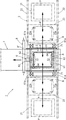
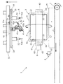
遊技機の自動解体処理装置1の概要を説明する。自動解体処理装置1は、遊技機を構成する枠状・パネル状・トレイ状又は箱状の構造体で、種々の構成部品が取り付けられる遊技機本体部に固定されている部品の取り付けネジを緩めて、それらの構成部品を取り除くもので、図1−図7に示すように、搬入機構2、保持機構3、リード線切断機構4、ネジ緩め機構5、姿勢変更機構6、ベルトコンベア7、磁力吸着機構8を備えてなる(図1ではリード線切断機構4及びネジ緩め機構5、図2−7では姿勢変更機構6の支持台の支柱61a、図3−7では搬入機構2についてそれぞれ記載省略されている。)。本実施形態では、遊技機本体として概ね矩形状の樹脂製パネル状の遊技盤Pから部品を取り外す場合について説明する。遊技盤Pの表裏両面Pa,Pbには、それぞれ多数の部品を層状に重ね合わせた状態で取り付けており、各部品はネジで締め付け固定されている。なお、部品の取り付けネジは、遊技盤Pの盤面に対して垂直方向に真っ直ぐ締め付けられているものが多いが、一部の取り付けネジについては、盤面に対して斜め向きに締め付けられている。なお、遊技盤Pの表裏両面Pa,Pbに取り付けられている部品及びリード線については記載を省略している。
(Outline of automatic dismantling process 1)
An outline of the automatic
(自動解体処理1の作動)
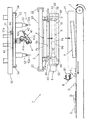
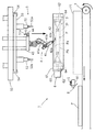
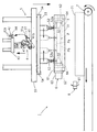
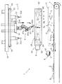
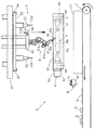
さて、図1に示される搬入機構2は、解体処理を行う装置内部(符号Aで示す位置)に遊技盤Pを順次搬入して、保持機構3に供給する。遊技盤Pは、図2において一点鎖線で示すように、保持機構3に保持されることにより、表面Paを上方に向けた横倒し姿勢にセットされる。遊技盤Pが保持機構3で位置決めされると、図3に示すように、上方に設けられているリード線切断機構4が降下して、ロボットアーム41の先端に装着されている自動切断工具42で、遊技盤Pの表面Paの固定部品に接続されているリード線を切断処理する。リード線の切断処理が終わると、ロボットアーム41が先端に装着している自動切断工具42を、工具ホルダー44に保持されている第1の自動ネジ緩め工具51(ネジ緩め機構5)に取り替えて、部品を固定している取り付けネジのうち斜め向きのものを順次緩める。第1の自動ネジ緩め工具51によるネジ緩め処理が終わると、図4に示すように、ロボットアーム41は、上方へ退避するとともに、次の処理に備えて、第1の自動ネジ緩め工具51を自動切断工具42に取り替える。上昇するロボットアーム41と入れ替わりに、第2の自動ネジ緩め工具52(ネジ緩め機構5)が降下し、水平方向にスライド移動しながら、垂直に向けられた取り付けネジを緩める。第2の自動ネジ緩め工具52が予定していたネジを緩め終わって上方に退避すると、図5に示すように、保持機構3を回転可能に支持する姿勢変更機構6が作動して、遊技機Pの向きを上下反転させる姿勢変更を行う。これにより、取り付けネジを緩めた部品取り付け面(遊技盤Pの表面Pa)が下方に向けられて、図6に示すように、ネジを緩められた表層部の部品GがネジSと共に下方のベルトコンベア7上に落とされる。また、姿勢変更機構6のサーボモータ63により、遊技盤Pを小刻みに振動回転させることで、遊技盤Pに引っ掛かっている部品GやネジSが確実に離脱・落下させられる。このとき、上方に向けられている他方の部品取り付け面(遊技盤Pの裏面Pb)に対して行われる次の工程(リード線の切断処理)に備えて、リード線切断機構4が降下を開始する。落下した部品GやネジSは、図6及び図7に示すように、ベルトコンベア7によって装置外部に搬出され、ネジSを主とする鉄製部品は、ベルトコンベア7の上方を横断するように設けられる磁力吸着機構8により回収される。
(Operation of automatic dismantling process 1)
Now, the carry-in
遊技盤Pの振動回転が終了すると、図7に示すように、裏面Pbに対するリード線の切断処理が開始される。裏面Pbに対しても、表面Paについての上記処理内容と同様に、第1の自動ネジ緩め機構51と第2の自動ネジ緩め機構52によるネジ緩め処理が行われる。そして、遊技盤Pが上下反転及び振動回転させられ、今度は、裏面Pbにおいてネジを緩められた表層部の部品GとネジSが落下して、ベルトコンベア7で装置外部に搬出され、ネジSを主とする鉄製部品は磁力吸着機構8により回収される。このとき、最初に表層部の部品を取り外された表面Paについて、表層部の部品を取り外したことで現れたリード線や部品に対する切断処理や緩め処理が開始される。以降、複数層の部品がすべて取り除かれるまで、図3−図7で示すのと同様に、リード線切断処理、ネジ緩め処理、上下反転処理、振動回転処理からなる一連の処理工程が、一枚の遊技盤Pの表面Paと裏面Pbに対して交互に繰り返し実施される。遊技盤Pについて予定していたすべての解体処理工程が終了したときに、保持機構3による保持を解除し、図2に示すように、解体処理が終了した遊技機Pをベルトコンベア7上に落下させると共に、次の新たな遊技盤Pを搬入機構2から受け入れて保持する。なお、リード線切断機構4で処理するリード線や、第1の自動ネジ緩め機構51で処理する斜め向きのネジが存しない面に対しては、リード線切断機構4を降下させずに、第2の自動ネジ緩め工具52によるネジ緩め処理のみを行う。また、表面Pa又は裏面Pbの一方について、取り外し部品が存しない場合や、既にすべての部品が取り外されている場合には、他方の部品取り付け面についてのみ処理を繰り返す。すなわち、遊技盤Pの上下反転及び振動回転により部品を下方に落とした後、すぐに遊技盤Pの向きを元に戻すように再び上下反転し、同じ部品取り付け面についてリード線切断処理やネジ緩め処理を連続的に実施する。なお、遊技機の機種により、遊技盤自体の形状や取り付けられているリード線や構成部品の形状・配置が異なるため、自動解体処理装置1の運転を開始する際には、解体処理する遊技機の機種に応じて、遊技盤を保持する保持機構3の枠体31を事前に組み替えたり、処理内容を予め設定・記憶されている処理プログラムの中から選択したりする事前準備を行う必要がある。
When the vibration rotation of the game board P is completed, the lead wire cutting process for the back surface Pb is started as shown in FIG. Also for the back surface Pb, the screw loosening process by the first automatic
(搬入機構2)
搬入機構2は、図1及び図2に示すように、保持機構3の左右両側方に設けられる2台のストック台21,21(図2は記載省略。)と、ストック台21,21と保持機構3の上方をつなぐように平行に延びる2本の搬送レール22,22と、搬送レール22,22でスライド支持され、各ストック台21と保持機構3の間をそれぞれ往復する2台の搬送シャトル23,23を備えてなる。ストック台21,21の上面には、上流工程から搬送されて解体処理を待つ遊技盤Pが載置されている。搬送シャトル23,23は、それぞれ下面側に突出する4本の把持爪23aを有しており、右側の搬送シャトル23は、右側のストック台21において、また、左側の搬送シャトル23は、左側のストック台21において、それぞれ遊技盤Pを把持爪23aで把持して、ストック台21と保持機構3の中間位置(図1に符号Bで示される位置)で待機する。保持機構3で保持されていた遊技盤Pの解体処理が終了して、図2に示すように下方に落とされるときに、いずれか一方の搬送シャトル23が、保持機構3の上方まで移動し、把持爪23aによる把持を解除して、保持機構3に新たな遊技盤Pを落下供給する。なお、本実施例では、左右2台の搬送シャトル23,23が設けられているが、これは、取り付け部品が少ない遊技盤Pを解体処理する場合など、1台の搬送シャトルのみでは遊技盤の供給が時間的に追い付かなくなることを考慮したものである。したがって、1台の遊技盤Pを解体処理するのに時間がかかる場合は、1台の搬送シャトルのみを稼働させてもよく、最初から1台のみ設けることにしても良い。
(Import mechanism 2)
As shown in FIGS. 1 and 2, the carry-in
(保持機構3)
保持機構3は、遊技盤Pを表裏どちらからでも受け入れ可能な矩形状の枠体31を有しており、図1−図7に示すように、遊技盤Pを枠内に収容し保持する。枠体31の長手方向の両端には、図1−図7に示すように、枠内に突出して、遊技盤Pが枠体31から外れないように、遊技盤Pを表裏両側から保持する複数個(8個)の保持爪32が設けられている。保持爪32は、図示しないアクチュエータにより駆動され、保持機構3に遊技盤Pが供給される際には、図2に示すように、上面側の保持爪32は枠体31自体の内部に収納されており、下面側の保持爪32のみが枠体31の内側空間に突出している。遊技盤Pが上方から供給されると、図1及び図3−図7に示すように、上面側の保持爪32も枠体31の内側空間に突出し、遊技盤Pが枠体31から外れないように表裏両面から保持する。これにより、図5−図7に示すように、枠体31を上下反転させても、遊技盤Pが外れて落ちることはない。遊技盤Pのすべての部品が取り外されて解体処理が終了すると、保持爪32が退避して枠体31自体の内部に収納されることにより、遊技盤Pは保持を解除されて、ベルトコンベア7上に落下する。次の遊技盤Pが供給されるときには、受け入れのため、また図2に示すように下面側の保持爪32のみを突出させる。なお、枠体31は、支持台61によって回動可能に支持されているが、上下反転時(図5)と振動回転時(図6)以外は、支持台61から突出する回り止め64により回転しないようにロックされており、遊技盤Pは、図1−図4、図6及び図7に示すように、表面Pa及び裏面Pbが略水平状態となる横倒しされた姿勢にセットされる。
(Holding mechanism 3)
The
(リード線切断機構4)
リード線切断機構4は、図2−図7に示すように、不図示の昇降機構により上下方向に移動する支持部材43と、支持部材43に支持されるロボットアーム41と、ロボットアーム41の先端に装着される自動切断工具42を備えてなり、図3に示すように、支持部材43を降下させて、保持機構3で所定の水平姿勢にセットされた遊技盤Pの表面Paに接近し、さらにロボットアーム41を作動させて切断対象のリード線に接近し、自動切断工具42でリード線を切断する。リード線の切断箇所が複数ある場合は、自動切断工具42がロボットアーム41によって場所を移動する。なお、ロボットアーム41は、支持部材43に連結される上部アーム41aの根元部分及び下部アーム41bの工具装着部分が360度回転可能とされており、更に上部アーム41aの根元部分及び上部アーム41aと下部アーム41bの連結部分に関節を有しており、遊技盤Pの各部に対して容易に接近することができる。自動切断工具42は、先端に設けられた二枚の刃物42a,42aをアクチュエータで開閉して、リード線を鋏むように切断する鋏状工具であるが、それだけでは撚り合わせたリード線を形成する極細の金属線や伸縮性のある被覆材を切断し切れないことがある。そこで、自動切断工具42は、鋏んだリード線を二枚の刃物42a,42aの周囲に巻き付けるように自転して、リード線を引っ張るとともに刃物42a,42aの刃部に強く当てるようにして確実に切断する。リード線は、縦方向、横方向、斜め方向の様々な向きに配索されるが、ロボットアーム41によれば、自動切断工具42の向きを自在に変えることにより対応が可能である。支持部材43には、ロボットアーム41に対して取り替え可能に装着される自動切断工具42と第1の自動ネジ緩め工具51を保持する工具ホルダー44が固定されている。
(Lead wire cutting mechanism 4)
As shown in FIGS. 2 to 7, the lead
(ネジ緩め機構5)
ネジ緩め機構5は、図2−図7に示すように、ロボットアーム41に装着されている自動切断工具42と取り替え可能に装着される第1の自動ネジ緩め工具51と、略水平方向に延びるレール53にスライド可能に支持される第2の自動ネジ緩め工具52,52を備えてなる。自動切断工具42によるリード線の切断処理が終了すると、ロボットアーム41は、工具ホルダー44に接近して、自動切断工具42を工具ホルダー44に係合保持させてから切り離し、既に工具ホルダー44に係合保持されている第1の自動ネジ緩め工具51を装着した後、遊技盤Pに接近してネジ緩め処理を開始する。第1の自動ネジ緩め工具51には、モーターで自動回転するネジ回し工具51aが取り付けられており、これを対象となるネジの頭部に係合させて回転することでネジを緩める。ネジは緩められるにつれて締付け穴から出っ張るが、ネジ回し工具51aもそれに応じて後退するように設定されている。予定していたネジをすべて緩め終わると、図4に示すように、支持部材43が上昇するとともに、ロボットアーム41が先端を上向きにして、後述する第2の自動ネジ緩め機構52やレール53と干渉しないように上方に折りたたまれた状態で待機する。このとき、後の処理工程の内容に応じて、工具ホルダー44に接近して、第1の自動ネジ緩め工具51を自動切断工具42に取り替える。なお、自動切断工具42で切断処理すべきリード線が無い場合は、第1の自動ネジ緩め工具51によるネジ緩め処理のみを実施し、第1の自動ネジ緩め工具51によりネジ緩め処理すべきネジが無い場合は、自動切断工具42による切断処理のみを実施し、自動切断工具42により切断処理するリード線と第1の自動ネジ緩め工具51によりネジ緩め処理するネジのいずれも無い場合には、支持部材43を降下させることなく、支持部材55を降下させて、後述する第2の自動ネジ緩め工具52によるネジ緩め処理を開始する。
(Screw loosening mechanism 5)
As shown in FIGS. 2 to 7, the
第2の自動ネジ緩め工具52,52は、第1の自動ネジ緩め工具51と同様に、モーターで自動回転するネジ回し工具52a,52aが取り付けられており、これらをネジの頭部に係合させて回転することでネジを緩める。ネジ回し工具52a,52aは、ネジが緩められるにつれて締付け穴から出っ張るのに合わせて後退するように設定されている。第2の自動ネジ緩め工具52,52は、略水平方向に延びるレール53に係合支持され、不図示の駆動機構によりレール53の長手方向(図2−図7の紙面における左右方向)にスライド移動可能とされている。レール53は、両端を略水平方向に延びる2本の平行なレール54,54に係合支持され、不図示の駆動機構によりレール54,54の長手方向(図2−図7の紙面と直交する方向)にスライド移動可能とされている。レール54,54は、不図示の昇降機構により上下方向に移動する支持部材55に支持されている。すなわち、第2の自動ネジ緩め工具52,52は、いわゆるX−Y方向の水平移動が可能であり、遊技盤Pにおいて垂直方向に締め付けられたネジであれば、何れの位置にあるネジでもそれに相対向する位置まで移動して、それらのネジをすべて緩めることができる。ここでは、第2の自動ネジ緩め工具52は、2台としたが、1台又は3台以上にしてもよく、レール53を2本以上にしてもよい。例えば、レール53を2本設けるとともに、各レールに4台ずつ計8台の第2の自動ネジ緩め工具52を設けることにしてもよい。なお、支持部材55は、ロボットアーム41、支持部材43及び工具ホルダー44が内側を通過できる大きさの枠型に形成されているが、ロボットアーム41による処理と、第2の自動ネジ緩め工具による処理を同時に実施すると、相互に干渉して故障の原因となるため、図3に示されるように、ロボットアーム41が下降しているときは、第2の自動ネジ緩め工具52が支持部材55において端に寄せられた状態で上方に退避しており、図4に示されるように、第2の自動ネジ緩め工具52が下降しているときは、ロボットアーム41が上方に退避している。
Similar to the first automatic
(姿勢変更機構6)
姿勢変更機構6は、矩形状の枠状体で四隅に設置用の支柱61a(図1)を有してなる支持台61と、支持台61に設けられて保持機構3の枠体31を回動可能に支持する回転軸62,62と、同じく支持台61に設けられて一方の回転軸62に連結され、枠体31を回転させて所定角度位置で制動停止させるサーボモータ63を備えてなる。これにより、姿勢変更機構6は、遊技盤P(枠体31)を、リード線切断・ネジ緩め処理のために水平姿勢にセットした状態から、ネジを緩めた部品を落下させるために上下反転させた姿勢にすることができる。サーボモータ63は、遊技盤Pの表裏両面を上下反転させた後、小刻みに往復振動回転することにより枠体31(遊技盤P)に振動を与えて、遊技盤Pに引っ掛かって落ちにくい部品を確実に離脱・落下させる振動機構として機能する。支持台61には、枠体31が水平状態とされて遊技盤Pに対するリード線切断・ネジ緩め処理が行われるときに突出して、枠体31の下面を支持する回り止め64が設けられているが、枠体31を上下反転させたり、振動回転させたりするときには、図5及び図6に示すように後退して支持を解除する。なお、遊技盤Pを振動させる手段については、サーボモータによる枠体31の回転振動ではなく、他の振動機構を設けるようにしてもよく、振動方向は、回転方向のほか、縦方向、横方向、斜め方向としてもよく、これらの一部又は全部を選択した複合的な振動を与えるようにしてもよい。また、枠体31の角度を変えている途中に振動を与えるようにしてもよい。
(Attitude change mechanism 6)
The
(ベルトコンベア7)
ベルトコンベア7は、遊技盤Pが保持される保持機構3の下方位置から、搬入機構2の搬送レール22と直交する横方向へ延びるように設けられており、上下反転させられた遊技盤Pから落下した部品を受けて装置外部へ連続的に搬送する。なお、保持機構3の下方位置付近では、遊技盤Pから落下した部品がベルトコンベア7の搬送面から転がり落ちないように、搬送方向に平行に延びる保護カバー71などで周囲を囲まれている。
(Belt conveyor 7)
The belt conveyor 7 is provided so as to extend in a lateral direction perpendicular to the
(磁力吸着機構8)
ベルトコンベア7の上方で、かつ、保持機構3の下方位置から僅かに下流側に設けられ、ベルトコンベア7で搬送されてくる鉄製部品を磁力で吸着して回収する磁力吸着機構8が備えられている。磁力吸着機構8は、磁力を有するベルト部材81が連続回転しており、ベルトコンベア7上を搬送されてくるネジSを主とする鉄製部品をベルト部材81の磁力で吸着させ、ベルトコンベア7の側方へ搬送し、不図示の回収装置によりベルト部材81から離脱させて回収する。
(Magnetic adsorption mechanism 8)
A magnetic
(上記実施形態の変形例)
上記実施形態では、遊技機本体部として、パチンコ台の遊技盤Pに取り付けられている構成部品を取り外す例について説明したが、本発明は、遊技機を構成する枠状・パネル状・トレイ状又は箱状の構造体で、種々の構成部品が取り付けられるものに適用してもよい。例えば、パチンコ台の枠あるいはスロット台の前扉体や筐体に取り付けられている構成部品を取り外す場合に適用してもよい。更にパチンコ台の枠の一部を構成し、遊技機島に設置される外枠(固定枠)、外枠に対して開閉可能に収納設置される本体枠(遊技盤取付枠)、本体枠の前面に開閉可能に設けられるガラス扉枠(装飾枠)、及びこれらの枠を構成する枠状・パネル状・トレイ状又は箱状の構造体で、種々の構成部品が取り付けられるものに適用してもよい。
(Modification of the above embodiment)
In the above-described embodiment, the example of removing the components attached to the game board P of the pachinko machine as the gaming machine main body has been described. However, the present invention is not limited to the frame shape, the panel shape, the tray shape, or the like constituting the gaming machine. The present invention may be applied to a box-like structure to which various components are attached. For example, the present invention may be applied to removing a component attached to a pachinko machine frame or a front door body or housing of a slot machine. In addition, it constitutes a part of the frame of the pachinko machine, the outer frame (fixed frame) installed on the gaming machine island, the main body frame (game board mounting frame) that can be opened and closed with respect to the outer frame, Applicable to glass door frames (decorative frames) that can be opened and closed on the front, and frame-like, panel-like, tray-like or box-like structures that make up these frames, to which various components can be attached. Also good.
上記実施形態では、パネル状の構造体である遊技盤Pについて、表面Paと裏面Pbのいずれかの面を上向きにした水平状態でリード線切断及びネジ緩め処理(以下、ネジ緩め処理等という。)を行い、これを上下反転させてネジ緩め処理等した部品を落とす一方、上向きとなる反対側の面のネジ緩め処理等を実施し、また上下反転させるという工程を繰り返して、表面Pa及び裏面Pbから交互に部品を取り外すようにしたが、表面Paのみ又は裏面Pbのみについてネジ緩め処理等と部品を落とす処理を連続的に繰り返すこととしてもよい。また、部品を確実に落とせるのであれば、上記実施形態のようにネジ緩め処理等をした面を真下に向ける必要はなく、斜め下向きにする、横向きにする、又は上向きにしたままで面を傾斜させる(斜め上向きにする)だけに留めることとしてもよい。更にネジ緩め処理等を行う際においても、特に不都合がなければ、処理対象面を真上に向けておく必要はなく、斜め上向き、横向き、斜め下向きとしてもよい。なお、斜め上向き、横向き、斜め下向きでネジ緩め処理をする場合には、ロボットアームの先端に取り付けた自動ネジ緩め工具を使用することになる。 In the above embodiment, the gaming board P, which is a panel-like structure, is a lead wire cutting and screw loosening process (hereinafter referred to as a screw loosening process or the like) in a horizontal state where either the front surface Pa or the back surface Pb faces upward. ) And flipping it upside down to drop the screw loosening part, etc., while repeating the process of carrying out the screw loosening process etc. on the opposite side facing up and upside down, Although the parts are alternately removed from Pb, the screw loosening process or the like and the process of dropping the parts may be repeated continuously for only the front surface Pa or only the back surface Pb. In addition, if the part can be reliably dropped, it is not necessary to turn the screw-loosened surface or the like directly below as in the above-described embodiment, and the surface is inclined obliquely downward, horizontally, or upward. It is good also as just stopping it (it makes it diagonally upward). Further, when performing the screw loosening process or the like, if there is no particular inconvenience, the processing target surface does not need to be directed directly upward, and may be obliquely upward, laterally, or obliquely downward. In addition, when the screw loosening process is performed obliquely upward, laterally, and obliquely downward, an automatic screw loosening tool attached to the tip of the robot arm is used.
上記実施形態では、パネル状の構造体である遊技盤Pを解体処理する例について説明したが、パチンコ台の枠やスロット台の筐体のように、枠状・トレイ状又は箱状の構造体で開口部があり、開口部の周囲に側壁を有する遊技機本体部については、以下のようにして解体処理する。まず、開口部が上向きとなるように遊技機本体部をセットした状態で、開口部内の内側面(底面及び側壁面)に固定されている部品の取り付けネジを緩める。次に、開口部が下方に向くように、遊技機本体部の姿勢を変えて、開口部の内側にある部品を落下させる。ただし、側壁部に取り付けられていた部品については、側壁面に形成されている凹部などに嵌まり込んでいるなどして容易に落下しないこともあるため、振動機構により振動を与えるだけでなく、側壁面が真下を向くように開口部を横向きにしたり、遊技機本体の姿勢を様々に変えるようにして、その間、振動機構による振動を与えたりするようにしてもよい。 In the above embodiment, an example of disassembling the game board P, which is a panel-like structure, has been described. However, a frame-like, tray-like or box-like structure like a pachinko machine frame or a slot machine housing. The gaming machine main body having an opening and having a side wall around the opening is disassembled as follows. First, in a state in which the gaming machine main body is set so that the opening faces upward, the mounting screws of the parts fixed to the inner side surfaces (bottom surface and side wall surfaces) in the opening are loosened. Next, the posture of the gaming machine main body is changed so that the opening is directed downward, and the components inside the opening are dropped. However, for the parts attached to the side wall, it may not fall easily because it fits into a recess formed on the side wall surface, so not only give vibration by the vibration mechanism, You may make it give the vibration by a vibration mechanism in the meantime, making an opening sideways so that a side wall surface may face right below, or changing the attitude | position of a game machine main body variously.
上記実施形態では、ネジ緩め作業をした部品を確実に離脱・落下させるように、遊技盤Pを振動させる振動機構を採用したが、これに代えて遊技盤Pに衝撃力を加える衝撃機構を採用してもよい。例えば、保持機構31又は遊技盤Pを叩くハンマーを設けたり、保持機構31をスライド上昇させて落下させたりする機構を備えるようにしてもよい。
In the above embodiment, a vibration mechanism that vibrates the game board P is used so as to reliably remove and drop the parts that have been loosened, but instead, an impact mechanism that applies an impact force to the game board P is adopted. May be. For example, a hammer that strikes the
上記実施形態では、すべての部品を遊技盤Pから落下させることで取り除くようにしたが、液晶パネルなどの画像表示装置については、そのまま再利用することができるはずのものが落下させることで破損して使えなくなることがある。そこで、遊技機本体部を上下反転等させて部品を落下させる前に、必要な部品を保持して回収する保持回収機構を備えるようにしても良い。例えばバキュームで部品表面に吸着することにより部品を保持するバキューム式部品保持工具や、開閉する把持爪を閉じることにより部品を保持する把持式部品保持工具を、支持部材43に固定されている工具ホルダー44に予め係合保持させておき、ロボットアーム41が、自動切断工具42や第1の自動ネジ緩め工具52をこれらの部品保持工具に取り替えて回収処理を行う保持回収機構としてもよい。
In the above embodiment, all the parts are removed by dropping them from the game board P. However, image display devices such as liquid crystal panels are damaged by dropping those that can be reused as they are. May become unusable. Therefore, a holding and collecting mechanism that holds and collects necessary components may be provided before the gaming machine main body is turned upside down to drop the components. For example, a tool holder in which a vacuum-type component holding tool that holds a component by adsorbing to the surface of the component by vacuum or a grip-type component holding tool that holds a component by closing a holding claw that opens and closes is fixed to the
上記実施形態では、自動切断工具42、第1の自動ネジ緩め工具51、さらに上記変形例では、部品保持工具を工具ホルダー44に係合保持させておいて、ロボットアーム41がこれらを取り替え装着することにより各種処理を行うようにしたが、自動切断工具及び自動ネジ緩め工具の双方、又はこれらに部品保持工具を加えたものを切り換え可能に内蔵した複数工具をロボットアーム41の先端に装着しておき、処理内容に応じて使用する工具を相互に切り換えて使用することとしてもよい。
In the above embodiment, the
遊技機の自動解体処理装置は、上述したものに限らず、要旨を変更しない範囲で種々変更し得ることは勿論である。 Of course, the automatic dismantling processing apparatus of the gaming machine is not limited to the above-described one, and various changes can be made without departing from the scope of the invention.
1 自動解体処理装置
2 搬入機構
3 保持機構
4 リード線保持機構
41 ロボットアーム
42 自動切断工具
5 ネジ緩め機構
51 第1の自動ネジ緩め工具
52 第2の自動ネジ緩め工具
6 姿勢変更機構
7 ベルトコンベア
8 磁力吸着機構
DESCRIPTION OF
本願請求項8の発明は、前記ネジ緩め機構は、ロボットアームに装着される第1の自動ネジ緩め工具と、第1のレールに支持されて該第1のレールの長手方向にスライド移動可能な第2の自動ネジ緩め工具を備えてなり、更に前記第1のレールが、前記第1のレールと直交する方向に延びる第2のレールに支持されて該第2のレールの長手方向にスライド移動可能とされていることにより、第2の自動ネジ緩め工具がネジ緩め処理の対象となるネジに相対向する位置までスライド移動することを特徴とする請求項1乃至7のいずれかに記載の遊技機の自動解体処理装置置を提供する。
According to the invention of
本願請求項11の発明は、遊技機本体部の姿勢を変更して部品を落下させる際に遊技機本体部に衝撃力を加える衝撃機構を備えることを特徴とする請求項1乃至9のいずれかに記載の遊技機の自動解体処理装置を提供する。
The invention of claim 11 is any one of
本願請求項11の発明によれば、本願請求項1乃至9の発明が奏し得る効果に加えて、以下の優れた効果を奏し得る。緩めたネジの先端が遊技機本体部の締付け穴に引っ掛かっていたり、部品同士が絡み合っていたりして、落ちにくい部品でも遊技機本体部に衝撃を加えることで引っ掛かりや絡み合いが解消されて確実に離脱・落下させることができる。
According to the invention of claim 11 of the present application, in addition to the effects that the inventions of
(ネジ緩め機構5)
ネジ緩め機構5は、図2−図7に示すように、ロボットアーム41に装着されている自動切断工具42と取り替え可能に装着される第1の自動ネジ緩め工具51と、略水平方向に延びる第1のレール53にスライド可能に支持される第2の自動ネジ緩め工具52,52を備えてなる。自動切断工具42によるリード線の切断処理が終了すると、ロボットアーム41は、工具ホルダー44に接近して、自動切断工具42を工具ホルダー44に係合保持させてから切り離し、既に工具ホルダー44に係合保持されている第1の自動ネジ緩め工具51を装着した後、遊技盤Pに接近してネジ緩め処理を開始する。第1の自動ネジ緩め工具51には、モーターで自動回転するネジ回し工具51aが取り付けられており、これを対象となるネジの頭部に係合させて回転することでネジを緩める。ネジは緩められるにつれて締付け穴から出っ張るが、ネジ回し工具51aもそれに応じて後退するように設定されている。予定していたネジをすべて緩め終わると、図4に示すように、支持部材43が上昇するとともに、ロボットアーム41が先端を上向きにして、後述する第2の自動ネジ緩め機構52や第1のレール53と干渉しないように上方に折りたたまれた状態で待機する。このとき、後の処理工程の内容に応じて、工具ホルダー44に接近して、第1の自動ネジ緩め工具51を自動切断工具42に取り替える。なお、自動切断工具42で切断処理すべきリード線が無い場合は、第1の自動ネジ緩め工具51によるネジ緩め処理のみを実施し、第1の自動ネジ緩め工具51によりネジ緩め処理すべきネジが無い場合は、自動切断工具42による切断処理のみを実施し、自動切断工具42により切断処理するリード線と第1の自動ネジ緩め工具51によりネジ緩め処理するネジのいずれも無い場合には、支持部材43を降下させることなく、支持部材55を降下させて、後述する第2の自動ネジ緩め工具52によるネジ緩め処理を開始する。
(Screw loosening mechanism 5)
As shown in FIGS. 2 to 7, the
第2の自動ネジ緩め工具52,52は、第1の自動ネジ緩め工具51と同様に、モーターで自動回転するネジ回し工具52a,52aが取り付けられており、これらをネジの頭部に係合させて回転することでネジを緩める。ネジ回し工具52a,52aは、ネジが緩められるにつれて締付け穴から出っ張るのに合わせて後退するように設定されている。第2の自動ネジ緩め工具52,52は、略水平方向に延びる第1のレール53に係合支持され、不図示の駆動機構により第1のレール53の長手方向(図2−図7の紙面における左右方向)にスライド移動可能とされている。第1のレール53は、両端を略水平方向に延びる2本の平行な第2のレール54,54に係合支持され、不図示の駆動機構により第2のレール54,54の長手方向(図2−図7の紙面と直交する方向)にスライド移動可能とされている。第2のレール54,54は、不図示の昇降機構により上下方向に移動する支持部材55に支持されている。すなわち、第2の自動ネジ緩め工具52,52は、いわゆるX−Y方向の水平移動が可能であり、遊技盤Pにおいて垂直方向に締め付けられたネジであれば、何れの位置にあるネジでもそれに相対向する位置まで移動して、それらのネジをすべて緩めることができる。ここでは、第2の自動ネジ緩め工具52は、2台としたが、1台又は3台以上にしてもよく、第1のレール53を2本以上にしてもよい。例えば、第1のレール53を2本設けるとともに、各第1のレールに4台ずつ計8台の第2の自動ネジ緩め工具52を設けることにしてもよい。なお、支持部材55は、ロボットアーム41、支持部材43及び工具ホルダー44が内側を通過できる大きさの枠型に形成されているが、ロボットアーム41による処理と、第2の自動ネジ緩め工具による処理を同時に実施すると、相互に干渉して故障の原因となるため、図3に示されるように、ロボットアーム41が下降しているときは、第2の自動ネジ緩め工具52が支持部材55において端に寄せられた状態で上方に退避しており、図4に示されるように、第2の自動ネジ緩め工具52が下降しているときは、ロボットアーム41が上方に退避している。
Similar to the first automatic
Claims (15)
Priority Applications (1)
| Application Number | Priority Date | Filing Date | Title |
|---|---|---|---|
| JP2013211315A JP5431616B1 (en) | 2013-10-08 | 2013-10-08 | Automatic dismantling processing equipment for gaming machines |
Applications Claiming Priority (1)
| Application Number | Priority Date | Filing Date | Title |
|---|---|---|---|
| JP2013211315A JP5431616B1 (en) | 2013-10-08 | 2013-10-08 | Automatic dismantling processing equipment for gaming machines |
Publications (2)
| Publication Number | Publication Date |
|---|---|
| JP5431616B1 JP5431616B1 (en) | 2014-03-05 |
| JP2015073700A true JP2015073700A (en) | 2015-04-20 |
Family
ID=50396555
Family Applications (1)
| Application Number | Title | Priority Date | Filing Date |
|---|---|---|---|
| JP2013211315A Expired - Fee Related JP5431616B1 (en) | 2013-10-08 | 2013-10-08 | Automatic dismantling processing equipment for gaming machines |
Country Status (1)
| Country | Link |
|---|---|
| JP (1) | JP5431616B1 (en) |
Cited By (3)
| Publication number | Priority date | Publication date | Assignee | Title |
|---|---|---|---|---|
| JP7684752B1 (en) * | 2024-11-08 | 2025-05-28 | 株式会社大都技研 | Gaming machine |
| JP7684751B1 (en) * | 2024-11-08 | 2025-05-28 | 株式会社大都技研 | Gaming machine |
| JP7684750B1 (en) * | 2024-11-08 | 2025-05-28 | 株式会社大都技研 | Gaming machine |
Families Citing this family (1)
| Publication number | Priority date | Publication date | Assignee | Title |
|---|---|---|---|---|
| CN114178285B (en) * | 2021-10-19 | 2023-02-28 | 中国电器科学研究院股份有限公司 | A method for dismantling and recycling charging piles |
Citations (7)
| Publication number | Priority date | Publication date | Assignee | Title |
|---|---|---|---|---|
| JPS59142032A (en) * | 1983-02-02 | 1984-08-15 | Matsushita Electric Ind Co Ltd | Automatic screw loosening device |
| JPH06262449A (en) * | 1993-03-11 | 1994-09-20 | Honda Motor Co Ltd | Method for dismantling automobile |
| JPH09131456A (en) * | 1995-11-07 | 1997-05-20 | Heiwa Corp | Recycling method for amusement machines |
| JPH1142519A (en) * | 1997-07-30 | 1999-02-16 | Mitsubishi Electric Corp | Screw removal device for waste home appliances |
| JPH11156775A (en) * | 1997-12-01 | 1999-06-15 | Shin Sangyo Souzou Kenkyu Kiko | Dismantling system using robot |
| JP2000099729A (en) * | 1998-09-21 | 2000-04-07 | Mitsubishi Electric Corp | Display device disassembly information collection device and display device disassembly system |
| JP2002186716A (en) * | 2000-12-21 | 2002-07-02 | Soei Koki Kk | Fixture for pachinko game machine, carrier for pachinko game machine, and system and working method using them |
-
2013
- 2013-10-08 JP JP2013211315A patent/JP5431616B1/en not_active Expired - Fee Related
Patent Citations (7)
| Publication number | Priority date | Publication date | Assignee | Title |
|---|---|---|---|---|
| JPS59142032A (en) * | 1983-02-02 | 1984-08-15 | Matsushita Electric Ind Co Ltd | Automatic screw loosening device |
| JPH06262449A (en) * | 1993-03-11 | 1994-09-20 | Honda Motor Co Ltd | Method for dismantling automobile |
| JPH09131456A (en) * | 1995-11-07 | 1997-05-20 | Heiwa Corp | Recycling method for amusement machines |
| JPH1142519A (en) * | 1997-07-30 | 1999-02-16 | Mitsubishi Electric Corp | Screw removal device for waste home appliances |
| JPH11156775A (en) * | 1997-12-01 | 1999-06-15 | Shin Sangyo Souzou Kenkyu Kiko | Dismantling system using robot |
| JP2000099729A (en) * | 1998-09-21 | 2000-04-07 | Mitsubishi Electric Corp | Display device disassembly information collection device and display device disassembly system |
| JP2002186716A (en) * | 2000-12-21 | 2002-07-02 | Soei Koki Kk | Fixture for pachinko game machine, carrier for pachinko game machine, and system and working method using them |
Cited By (3)
| Publication number | Priority date | Publication date | Assignee | Title |
|---|---|---|---|---|
| JP7684752B1 (en) * | 2024-11-08 | 2025-05-28 | 株式会社大都技研 | Gaming machine |
| JP7684751B1 (en) * | 2024-11-08 | 2025-05-28 | 株式会社大都技研 | Gaming machine |
| JP7684750B1 (en) * | 2024-11-08 | 2025-05-28 | 株式会社大都技研 | Gaming machine |
Also Published As
| Publication number | Publication date |
|---|---|
| JP5431616B1 (en) | 2014-03-05 |
Similar Documents
| Publication | Publication Date | Title |
|---|---|---|
| JP5431616B1 (en) | Automatic dismantling processing equipment for gaming machines | |
| US20150044948A1 (en) | Method for the multi-stage grinding of workpieces, and vacuum table, storage container, stripping device and plant for carrying out the method | |
| CN101234848B (en) | Substrate cutting splitting device and method | |
| CN104802510B (en) | A kind of pad printing machine | |
| CN101286461B (en) | Chip mounting apparatus and changing method for separation facilitation head in chip mounting apparatus | |
| JP2010129949A (en) | Component supply apparatus | |
| CN106530881A (en) | Multi-robot teaching and real training platform | |
| CN109608029B (en) | A glass substrate fully automatic cutting device and method | |
| CN105414913A (en) | Equipment integrating installation of computer main board battery and detachment of central processing unit (CPU) base protective cover and operation method thereof | |
| JP6295431B2 (en) | Insert head, component insertion device and component mounting line | |
| JP2009095925A (en) | Shot blasting device | |
| JP7220035B2 (en) | band saw | |
| CN102468513A (en) | Material taking method and material taking device for sheet materials | |
| JP5380956B2 (en) | Substrate fixing pallet and substrate processing apparatus | |
| KR101419317B1 (en) | Dicing apparatus and dicing method | |
| TW201609014A (en) | Slider assembly device and slider assembly method | |
| TW201815515A (en) | Tool changing method and machine tool using the same | |
| KR200483899Y1 (en) | Apparatus for withdrawing and laser-marking cast product | |
| JP5174432B2 (en) | Parts supply device | |
| JP6283819B2 (en) | Insert head, component insertion device and component mounting line | |
| JP2014099652A (en) | Component supply device | |
| KR101221429B1 (en) | PCB Protection Film Removal Device | |
| JP6684809B2 (en) | Mounting device and waste tape collection unit | |
| CN207942270U (en) | An automatic edge grinding equipment for copper clad laminate | |
| WO2015097865A1 (en) | Component mounting device and component mounting method |
Legal Events
| Date | Code | Title | Description |
|---|---|---|---|
| TRDD | Decision of grant or rejection written | ||
| A01 | Written decision to grant a patent or to grant a registration (utility model) |
Free format text: JAPANESE INTERMEDIATE CODE: A01 Effective date: 20131203 |
|
| A61 | First payment of annual fees (during grant procedure) |
Free format text: JAPANESE INTERMEDIATE CODE: A61 Effective date: 20131204 |
|
| R150 | Certificate of patent or registration of utility model |
Ref document number: 5431616 Country of ref document: JP Free format text: JAPANESE INTERMEDIATE CODE: R150 |
|
| R250 | Receipt of annual fees |
Free format text: JAPANESE INTERMEDIATE CODE: R250 |
|
| R250 | Receipt of annual fees |
Free format text: JAPANESE INTERMEDIATE CODE: R250 |
|
| LAPS | Cancellation because of no payment of annual fees |