JP2015055294A - Holder device with aligning mechanism, radial bearing device, and bolt with aligning mechanism - Google Patents
Holder device with aligning mechanism, radial bearing device, and bolt with aligning mechanism Download PDFInfo
- Publication number
- JP2015055294A JP2015055294A JP2013188877A JP2013188877A JP2015055294A JP 2015055294 A JP2015055294 A JP 2015055294A JP 2013188877 A JP2013188877 A JP 2013188877A JP 2013188877 A JP2013188877 A JP 2013188877A JP 2015055294 A JP2015055294 A JP 2015055294A
- Authority
- JP
- Japan
- Prior art keywords
- bolt
- plate
- holder
- elastic body
- holder device
- Prior art date
- Legal status (The legal status is an assumption and is not a legal conclusion. Google has not performed a legal analysis and makes no representation as to the accuracy of the status listed.)
- Granted
Links
Images


Abstract
Description
本発明は、柱状または筒状の保持対象を保持するホルダに関し、特に、ホルダの調心機構に関する。 The present invention relates to a holder for holding a columnar or cylindrical holding object, and more particularly to a holder alignment mechanism.
従来、回転体のラジアル方向の荷重を支持するラジアル軸受が知られている。例えば、特許文献1に示すように、円柱状のラジアル軸受は、その外周面に形成された軸受面により円筒状の回転体の内周面をラジアル方向に支持する。また、例えば、特許文献2に示すように、円筒状のラジアル軸受は、その内周面に形成された軸受面により円柱状の回転体の外周面をラジアル方向に支持する。
Conventionally, a radial bearing that supports a radial load of a rotating body is known. For example, as shown in
一般に、ラジアル軸受は、ラジアル軸受を保持するホルダによって所望の姿勢に保たれる。しかし、このためには、ホルダをベースに精度よく取り付けなければならず、その作業が困難であった。例えば、長尺物の軸心方向の両端部を、それぞれ、ラジアル軸受を介して別個のホルダで保持する場合、芯出し作業が煩雑で作業者の負担が大きい。そこで、例えば、特許文献3には、外周面が球状に形成された外輪を有するラジアル軸受をホルダに組み込んで、このラジアル軸受の外輪の外周面を、ホルダに形成された球面座で支持することにより、自動調心可能とした調心機構付軸受装置が提案されている。このような調心機構付軸受装置を用いることにより芯出し作業が容易となる。 Generally, a radial bearing is maintained in a desired posture by a holder that holds the radial bearing. However, for this purpose, the holder must be attached to the base with high accuracy, and the operation is difficult. For example, when both ends of the long object in the axial direction are held by separate holders via radial bearings, the centering operation is complicated and the burden on the operator is large. Therefore, for example, in Patent Document 3, a radial bearing having an outer ring whose outer peripheral surface is formed in a spherical shape is incorporated in a holder, and the outer peripheral surface of the outer ring of this radial bearing is supported by a spherical seat formed in the holder. Thus, a bearing device with an aligning mechanism capable of automatic alignment has been proposed. By using such a bearing device with a centering mechanism, the centering operation is facilitated.
しかしながら、上記の調心機構付軸受装置では、ホルダに、ラジアル軸受の外輪の外周面と対面する球面座を高精度に形成しなければならず、コストが嵩む。 However, in the above bearing device with a centering mechanism, a spherical seat facing the outer peripheral surface of the outer ring of the radial bearing must be formed with high accuracy in the holder, which increases costs.
本発明は上記事情に鑑みてなされたものであり、その目的は、より低コストの調心機構付ホルダ装置を提供することにある。 The present invention has been made in view of the above circumstances, and an object thereof is to provide a lower-cost holder device with an aligning mechanism.
上記課題を解決するために、本発明では、柱状または筒状の保持対象を保持するホルダをプレート上に固定するとともに、このプレートに、プレートの上面および下面を貫く貫通穴を設ける。そして、プレートの貫通穴に、この貫通穴より小径の軸部を有するボルトを挿入して、このボルトを、プレートが載置されるベースに設けられたネジ穴に螺合させる。ここで、ボルトの軸部は、このボルトの軸心方向に伸縮する第一および第二の弾性体に挿入されている。第一の弾性体は、ボルトの頭部とプレートの上面との間に配されており、ボルトとベースのネジ穴との螺合によってボルトの軸心方向にプリロードされる。第二の弾性体は、プレートの下面とベースとの間に配されており、ボルトとベースのネジ穴との螺合によってボルトの軸心方向にプリロードされる。 In order to solve the above problems, in the present invention, a holder for holding a columnar or cylindrical holding object is fixed on a plate, and through holes are provided in the plate so as to penetrate the upper and lower surfaces of the plate. Then, a bolt having a shaft portion smaller in diameter than the through hole is inserted into the through hole of the plate, and this bolt is screwed into a screw hole provided in the base on which the plate is placed. Here, the axial part of the bolt is inserted into first and second elastic bodies that expand and contract in the axial direction of the bolt. The first elastic body is disposed between the head of the bolt and the upper surface of the plate, and is preloaded in the axial direction of the bolt by screwing the bolt and the screw hole of the base. The second elastic body is disposed between the lower surface of the plate and the base, and is preloaded in the axial direction of the bolt by screwing the bolt and the screw hole of the base.
例えば、本発明は、ベース上で柱状あるいは筒状の保持対象を保持する調心機構付ホルダ装置であって、
前記保持対象を保持するホルダと、
前記ホルダが固定されたプレートと、
前記プレートを前記ベースに取り付けるためのボルトを有する調心機構付ボルトと、を備え、
前記プレートは、
前記ボルトに対応付けられて形成され、当該ボルトの軸部より大径の貫通穴を有し、
前記調心機構付ボルトは、
前記ボルトの前記軸部に挿入され、当該ボルトの軸心方向に伸縮する第一および第二の弾性体を有し、
前記第一の弾性体は、
前記ボルトの頭部と前記プレートの前記上面との間に配置され、当該ボルトと前記ベースのネジ穴との螺合により、当該ボルトの軸心方向にプリロードされ、
前記第二の弾性体は、
前記プレートの前記下面と前記ベースとの間に配置され、前記ボルトと前記ベースの前記ネジ穴との螺合により、当該ボルトの軸心方向にプリロードされる。
For example, the present invention is a holder device with a centering mechanism for holding a columnar or cylindrical holding object on a base,
A holder for holding the holding object;
A plate to which the holder is fixed;
A bolt with a centering mechanism having a bolt for attaching the plate to the base;
The plate is
Formed in association with the bolt, having a through-hole having a larger diameter than the shaft portion of the bolt,
The bolt with the aligning mechanism is
Having first and second elastic bodies inserted into the shaft portion of the bolt and extending and contracting in the axial direction of the bolt;
The first elastic body is
It is arranged between the head of the bolt and the upper surface of the plate, and is preloaded in the axial direction of the bolt by screwing the bolt and the screw hole of the base,
The second elastic body is
It is arranged between the lower surface of the plate and the base, and is preloaded in the axial direction of the bolt by screwing the bolt and the screw hole of the base.
本発明において、ボルトがプレートの貫通穴に挿入されてベースのネジ穴に螺合すると、ボルトの軸部に挿入され、ボルトの頭部とプレートの上面との間に配置された第一の弾性体が、ボルトの軸心方向にプリロードされるとともに、ボルトの軸部に挿入され、プレートの下面とベースとの間に配置された第二の弾性体が、ボルトの軸心方向にプリロードされる。その結果、プレートの貫通穴内においてボルトが相対的に傾斜可能な範囲で、プレートに固定されたホルダが、保持対象の軸心の位置に合わせて姿勢を変化させるとともに、その姿勢を安定に保持する。このため、ボルトの軸部に第一および第二の弾性体が挿入された簡易な構造を用いてホルダを自動調心することができ、したがって、本発明によれば、低コストの調心機構付ホルダ装置を提供できる。 In the present invention, when the bolt is inserted into the through hole of the plate and screwed into the screw hole of the base, the first elastic member is inserted into the shaft portion of the bolt and disposed between the head of the bolt and the upper surface of the plate. The body is preloaded in the axial direction of the bolt and inserted into the axial portion of the bolt, and the second elastic body disposed between the lower surface of the plate and the base is preloaded in the axial direction of the bolt. . As a result, the holder fixed to the plate changes its posture according to the position of the axis of the holding target and stably holds the posture within a range in which the bolt can be relatively inclined in the through hole of the plate. . For this reason, the holder can be automatically aligned using a simple structure in which the first and second elastic bodies are inserted into the shaft portion of the bolt. Therefore, according to the present invention, a low-cost alignment mechanism is provided. An attached holder device can be provided.
以下に、本発明の一実施の形態について、本実施の形態に係る調心機構付ホルダ装置2をラジアル軸受装置1に用いた場合を例にとり説明する。
Hereinafter, an embodiment of the present invention will be described by taking as an example the case where the holder device 2 with a centering mechanism according to the present embodiment is used in a radial bearing
図1は、本実施の形態に係る調心機構付ホルダ装置2を用いたラジアル軸受装置1の斜視図である。
FIG. 1 is a perspective view of a radial bearing
図示するように、ラジアル軸受装置1は、円柱状のエアロール3と、エアロール3を保持する一対の調心機構付ホルダ装置2と、を備えている。エアロール3は、円筒状の回転部材31と、回転部材31内に挿入されたシャフト32と、を有している。シャフト32の外周には、例えば回転部材31の両端部の位置に、回転部材31の内周面に対向する環状の静圧気体軸受(不図示)が取り付けられており、回転部材31は、これらの静圧気体軸受により回転可能に非接触支持される。また、シャフト32は、回転部材31よりも軸方向の長さが長く、その軸方向の両側の端部320が回転部材31の両側の端面310から突き出ている。そして、一対の調心機構付ホルダ装置2は、エアロール3のシャフト32の両側の端部320を保持する。
As shown in the figure, the radial bearing
上記構成のラジアル軸受装置1は、例えばつぎのようにして組み立てられる。すなわち、一対の調心機構付ホルダ装置2を、適切な位置に配置されたベース4上に固定する。それから、エアロール3のシャフト32の両側の端部320を、ベース4上に固定された一対の調心機構付ホルダ装置2に取り付ける。このようにして組み立てられたラジアル軸受装置1は、所定の高さの位置で、回転部材31の内周面をラジアル方向に支持する。
The radial bearing
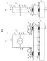
図2(A)および図2(B)は、本実施の形態に係る調心機構付ホルダ装置2の正面図および側面図であり、図3(A)は、図2(B)に示す調心機構付ホルダ装置2のA−A断面図であり、図3(B)は、図2(A)に示す調心機構付ホルダ装置2のB−B断面図である。 2 (A) and 2 (B) are a front view and a side view of the holder device 2 with an aligning mechanism according to the present embodiment, and FIG. 3 (A) is an adjustment shown in FIG. 2 (B). It is AA sectional drawing of the holder apparatus 2 with a center mechanism, and FIG.3 (B) is BB sectional drawing of the holder apparatus 2 with a centering mechanism shown to FIG. 2 (A).
図示するように、調心機構付ホルダ装置2は、エアロール3のシャフト32を保持するためのホルダ20と、ホルダ20を載置するためのプレート23と、プレート23をベース4に自動調心可能に固定する一対の調心機構付ボルト24と、を備えている。
As shown in the figure, the holder device 2 with an aligning mechanism can automatically align the
ホルダ20は、上部ホルダ21および下部ホルダ22を有し、上部ホルダ21の下面210および下部ホルダ22の上面220には、それぞれ、エアロール3のシャフト32を上下から挟み込んで保持するための弧面(断面円弧状の曲面)211、221が形成されている。また、上部ホルダ21には、上部ホルダ21の上面212および下面210を貫くボルト挿入孔213が形成されており、下部ホルダ22の上面220には、このボルト挿入孔213と対向する位置にネジ穴222が形成されている。下部ホルダ22の上面220に形成された弧面221上にエアロール3のシャフト32の端部320を配置するとともに、上部ホルダ21の下面210に形成された弧面211をこのシャフト32の端部320上に配置し、それから、上部ホルダ21の各ボルト挿入孔213に六角穴付ボルト50を挿入して、下部ホルダ22の上面220に形成されたネジ穴222に螺合させる。これにより、エアロール3のシャフト32の端部320がホルダ20に保持される。
The
下部ホルダ22は、両側面225から突き出したフランジ224を下面223側に有する逆T字型をしている。このフランジ224には、上面226および底面228を貫くボルト挿入孔227が形成されている。
The
プレート23の上面230には、下部ホルダ22のフランジ224に形成されたボルト挿入孔227と対向する位置にネジ穴231が形成されている。下部ホルダ22の各ボルト挿入孔227に六角穴付ボルト51を挿入して、プレート23の上面230に形成されたネジ穴231に螺合させることにより、下部ホルダ22がプレート23上に固定される。
A
プレート23の両端部(プレート23の上面230に載置された下部ホルダ22のフランジ224より外側の部分)232には、それぞれ、プレート23の上面230および下面233を貫くボルト挿入孔234が形成されている。また、ベース4の上面40には、プレート23の両端部232に形成されたボルト挿入孔234と対向する位置にネジ穴41が形成されている。後述の調心機構付ボルト24の六角穴付ボルト240を、プレート23の各ボルト挿入孔234に挿入して、ベース4の上面40に形成されたネジ穴41に螺合させることにより、プレート23が、ベース4に対して自動調心可能に取り付けられる。
Bolt insertion holes 234 penetrating the
調心機構付ボルト24は、それぞれ、2つの環状弾性体(第一の環状弾性体242および第二の環状弾性体243)と、第一の環状弾性体242、プレート23のボルト挿入孔234および第二の環状弾性体243の内部に挿入され、ベース4のネジ穴41に締結される六角穴付ボルト240と、プレート23の板厚Tのほぼ半分の位置(プレート23のボルト挿入孔234のほぼ半分の深さの位置)で六角穴付ボルト240の軸部241の外周面250とプレート23のボルト挿入孔234の内壁235との間に介在するOリング244と、を備えている。
The aligning mechanism-equipped
第一の環状弾性体242および第二の環状弾性体243は、それぞれ、六角穴付ボルト240の軸心O1方向に積み重ねられた複数の皿ばね245と、複数の皿ばね245を積み重ね方向両側から挟み込む一対のワッシャ246と、を有している。このような構成により、第一の環状弾性体242および第二の環状弾性体243は、六角穴付ボルト240の軸心O1方向に伸縮する。
Each of the first annular
六角穴付ボルト240は、頭部247とネジ部249との間に、第一の環状弾性体242および第二の環状弾性体243の自然長(荷重がかかっていないときにおける2つのワッシャ246間の距離)とプレート23の板厚Tとの合計寸法よりも短い軸部241を有している。このため、この六角穴付ボルト240のネジ部249を、第一の環状弾性体242、プレート23のボルト挿入孔234および第二の環状弾性体243を介してベース4のネジ穴41に螺合させると、第一の環状弾性体242は、六角穴付ボルト240の頭部247の座面251とプレート23の上面230との間で六角穴付ボルト240の軸心O1方向にプリロードされる。また、第二の環状弾性体243も、プレート23の下面233とベース4の上面40との間で六角穴付ボルト240の軸心O1方向にプリロードされる。これにより、プレート23は、第一の環状弾性体242によりベース4に向かって付勢されながら、第二の環状弾性体243によりベース4上で弾性支持され、両方の環状弾性体242、243の力が釣り合う位置で安定に保持されている。
The hexagon socket
なお、図2ないし図4には、第一の環状弾性体242と第二の環状弾性体243とに同数の皿ばね245を用いた場合を一例として示しているが、第一の環状弾性体242と第二の環状弾性体243とで皿ばね245の枚数を異ならせてもよい。例えば、第一の環状弾性体242および第二の環状弾性体243における皿ばね245の枚数は、エアロール3が取り付けられた状態(図1の状態)で、六角穴付ボルト240の軸心O1に対するプレート23の傾斜角度の調整範囲に応じた撓みが得られるように定められていればよい。ただし、プレート23が六角穴付ボルト240の軸心O1に対して最大角度傾斜した場合でも(図4(A)および図4(B)参照)、プレート23の下面233がベース4の上面40と接触しないように、第二の環状弾性体243においては、荷重、プレート23の幅寸法等に応じて定めた枚数の皿ばね245が積み重ねられているものとする。
2 to 4 show an example in which the same number of disc springs 245 are used for the first annular
六角穴付ボルト240の軸部241の外周面250とプレート23のボルト挿入孔234の内壁235との間に、六角穴付ボルト240の軸心O1に対してプレート23が所定角度傾斜可能な隙間が形成されるように、六角穴付ボルト240の軸部241は、プレート23のボルト挿入孔234の孔径r1よりも所定の寸法だけ小さな軸径r2を有している。また、六角穴付ボルト240の軸部241の外周面250には、エアロール3が取り付けられた状態(図1の状態)において、プレート23のボルト挿入孔234の例えばほぼ半分の深さの位置に位置付けられる位置に、周方向の環状溝248が形成されている。
Between the outer
Oリング244は、六角穴付ボルト240の軸部241の環状溝248に嵌め込まれている。プレート23のボルト挿入孔234の内壁235にOリング244の全周が密着するように、Oリング244の径方向の厚さは、環状溝248の溝深さよりも大きく設定されている。これにより、調心機構付ボルト24の六角穴付ボルト240を、第一の環状弾性体242、プレート23のボルト挿入孔234および第二の環状弾性体243に挿入してベース4のネジ穴41に螺合させた場合に、プレート23のボルト挿入孔234のほぼ半分の深さの位置(軸心O2方向の中央付近)において、Oリング244が、このボルト挿入孔234の内壁235と当接する。このため、プレート23は、このOリング244を支点として、プレート23のボルト挿入孔234のほぼ半分の深さに位置する揺動中心C周りに揺動する(図4(A)および図4(B)参照)。
The O-
上記構成の調心機構付ボルト24は、例えばつぎのようにして、調心機構付ホルダ装置2に取り付けられる。すなわち、六角穴付ボルト240の軸部241を第一の環状弾性体242内を挿入するとともに、六角穴付ボルト240の軸部241の環状溝248にOリング244を取り付ける。つぎに、Oリング244が取り付けられた六角穴付ボルト240の軸部241をプレート23のボルト挿入孔234に挿入する。それから、プレート23の下面233側において、ボルト挿入孔234から突き出した六角穴付ボルト240の軸部241を、第二の環状弾性体243内に挿入する。そして、六角穴付ボルト240のネジ部249をベース4のネジ穴41に螺合させる。その後、六角穴付ボルト240の軸部241の軸方向下側の端面252がベース4の上面40に接触するまで、六角穴付ボルト240のネジ部249をベース4のネジ穴41に締め込む。これにより、上述したように、六角穴付ボルト240の頭部247の座面251とプレート23の上面230との間で第一の環状弾性体242がプリロードされるとともに、プレート23の下面233とベース4の上面40との間で第二の環状弾性体243がプリロードされる。
The
つぎに、調心機構付ホルダ装置2の自動調心機能について説明する。 Next, an automatic alignment function of the holder device 2 with an alignment mechanism will be described.
図4(A)および図4(B)は、調心機構付ホルダ装置2の自動調心機能を説明するための図であり、図3(B)に示す調心機構付ホルダ装置2のA部拡大図である。 4 (A) and 4 (B) are diagrams for explaining the automatic alignment function of the holder device 2 with the aligning mechanism, and FIG. 4 (A) of the holder device 2 with the aligning mechanism shown in FIG. 3 (B). FIG.
図示するように、調心機構付ボルト24の六角穴付ボルト240の軸部241の軸径r2は、プレート23のボルト挿入孔234の孔径r1よりも小径であり、この軸部241には、Oリング244がボルト挿入孔234の軸心O2方向の中央付近においてボルト挿入孔234の内壁235と当接するように取り付けられている。
As shown in the figure, the
このため、プレート23は、Oリング244を支点として、プレート23のボルト挿入孔234のほぼ半分の深さに位置する揺動中心(例えば、六角穴付ボルト240の軸心O1上の、Oリング244に囲まれた位置)C周り揺動することができる。ここで、調心機構付ボルト24の六角穴付ボルト240の軸心O1に対するプレート23の最大傾斜角度は、六角穴付ボルト240の軸部241がボルト挿入孔234の上下の開口部236に当接した場合における六角穴付ボルト240の軸心O1に対するボルト挿入孔234の軸心O2の傾斜角αである。この傾斜角αは、プレート23のボルト挿入孔234の孔径r1、六角穴付ボルト240の軸部241の軸径r2、およびプレート23の板厚Tに応じて定まる。
For this reason, the
また、第一の環状弾性体242および第二の環状弾性体243は、六角穴付ボルト240の軸心O1方向にプリロードされており、プレート23は、2つの環状弾性体242、243の力が釣り合う位置で安定に保持されている。ここで、プレート23が、外力を受けて六角穴付ボルト240の軸心O1に対して傾斜した場合、プレート23の下面233とベース4の上面40との間隔は、六角穴付ボルト240の軸心O1を挟んで一方の側(図4(A)では左側)において狭くなり、他方側(図4(A)では右側)において広がる。これとは逆に、六角穴付ボルト240の頭部247の座面251とプレート23の上面230との間隔は、プレート23の下面233とベース4の上面40との間隔が狭くなる一方の側(図4(A)では左側)において広がり、プレート23の下面233とベース4の上面40との間隔が広がる他方の側(図4(A)では右側)において狭くなる。このため、第二の環状弾性体243は、六角穴付ボルト240の軸心O1を挟んで一方側で圧縮されるとともに他方の側で引っ張られ、これとは逆に、第一の環状弾性体242は、六角穴付ボルト240の軸心O1を挟んで一方側で引っ張られるとともに他方の側で圧縮される。これにより、プレート23は、第一の環状弾性体242および第二の環状弾性体243から、プレート23の傾きを戻そうとする方向の復元力を受け、これらの復元力と外力とが釣り合う位置で安定に保持されている。
The first annular
その結果、プレート23に固定されたホルダ20は、調心機構付ボルト24の六角穴付ボルト240の軸部241が挿入されるプレート23のボルト挿入孔234の孔径r1、調心機構付ボルト24の六角穴付ボルト240の軸部241の軸径r2、およびプレート23の板厚Tに応じて定まる上記最大傾斜角度αまでの範囲内で、エアロール3のシャフト32の軸心に合わせて姿勢を変化させるとともに、その姿勢を安定に保持する。つまり、エアロール3のシャフト32の軸心の位置に応じて自動調心される。
As a result, the
以上、本発明の一実施の形態について説明した。 The embodiment of the present invention has been described above.
本実施の形態に係る調心機構付ホルダ装置2では、エアロール3のシャフト32を保持するホルダ20をプレート23上に固定するとともに、このプレート23の両端部232に、プレート23の上面230および下面233を貫くボルト挿入孔234を設けている。そして、プレート23のボルト挿入孔234に、このボルト挿入孔234より小径の軸部241を有する調心機構付ボルト24の六角穴付ボルト240を挿入して、この六角穴付ボルト240をベース4のネジ穴41に螺合させる。ここで、六角穴付ボルト240の軸部241は、六角穴付ボルト240の軸心O1方向に伸縮する第一の環状弾性体242および第二の環状弾性体243とOリング244に挿入されている。
In the holder device 2 with a centering mechanism according to the present embodiment, the
第一の環状弾性体242は、六角穴付ボルト240の頭部247とプレート23の上面230との間に配置され、六角穴付ボルト240のネジ部249とベース4のネジ穴41との螺合により、六角穴付ボルト240の軸心O1方向にプリロードされている。また、第二の環状弾性体243は、プレート23の下面233とベース4の上面40との間に配置され、六角穴付ボルト240のネジ部249とベース4のネジ穴41との螺合により、六角穴付ボルト240の軸心O1方向にプリロードされている。
The first annular
その結果、調心機構付ボルト24の六角穴付ボルト240の軸部241が挿入されるプレート23のボルト挿入孔234の孔径r1、調心機構付ボルト24の六角穴付ボルト240の軸部241の軸径r2、およびプレート23の板厚Tに応じて定まる傾斜角度の範囲で、プレート23上に固定されたホルダ20は、エアロール3のシャフト32の軸心に合わせて自動調心される。このため、ホルダ20に球面加工を施さなくても、六角穴付ボルト240の軸部241に第一の環状弾性体242、第二の環状弾性体243およびOリング244が挿入された簡易な構造の調心機構付ボルト24を用いて自動調心することができる。したがって、本実施の形態によれば、低コストの調心機構付ホルダ装置2を提供できる。
As a result, the hole diameter r1 of the
また、上記の実施の形態においては、調心機構付ボルト24を取り付けるためのボルト挿入孔234が形成されたプレート23を用いることにより、既製のホルダ2をそのまま用いることができるため、さらにコストを削減することができる。
Further, in the above embodiment, the ready-made holder 2 can be used as it is by using the
また、本実施の形態に係る調心機構付ホルダ装置2では、調心機構付ボルト24の六角穴付ボルト240の軸心O1方向に積み重ねられた複数の皿ばね245と、これらの皿ばね245を積み重ね方向に挟み込む一対のワッシャ246と、を有する第一の環状弾性体242および第二の環状弾性体243を用いている。このため、積み重ねる皿ばね245の枚数を調節することにより、保持対象のエアロール3に合わせて、これらの環状弾性体242、243の伸縮量、弾性力等を個別に調節することできる。
Further, in the holder device 2 with the aligning mechanism according to the present embodiment, a plurality of disc springs 245 stacked in the direction of the axis O1 of the hexagon
また、本実施の形態に係る調心機構付ホルダ装置2では、エアロール3が取り付けられた状態(図1の状態)でプレート23のボルト挿入孔234のほぼ半分の深さの位置においてボルト挿入孔234の内壁235と当接するように、Oリング244が調心機構付ボルト24の六角穴付ボルト240の軸部241に取り付けられている。このようにすることにより、プレート23は、Oリング244を支点として、六角穴付ボルト240の軸心O1に対し傾斜するので、例えば、六角穴付ボルト240の軸部241がボルト挿入孔234の内壁235と六角穴付ボルト240の軸心O1方向において全面に亘って当接し、その結果、自動調心できなくなる事態が発生するのを防止することができる。
Further, in the holder device 2 with the aligning mechanism according to the present embodiment, the bolt insertion hole at a position that is approximately half the depth of the
なお、本発明は上記の実施の形態に限定されるものではなく、その要旨の範囲内で数々の変形が可能である。 In addition, this invention is not limited to said embodiment, Many deformation | transformation are possible within the range of the summary.
例えば、上記の実施の形態では、調心機構付ボルト24の第一および第二の環状弾性体242、243として、六角穴付ボルト240の軸心O1方向に積み重ねられた複数の皿ばね245と、これらの皿ばね245を積み重ね方向両側から挟み込む一対のワッシャ246と、を有するものを用いているが、本発明はこれに限定されない。例えば、確実にプレート23をベース4に向かって付勢しながらベース4上で弾性支持することができれば、必ずしもワッシャ246を用いる必要はない。また、第一および第二の環状弾性体242、243は、六角穴付ボルト240の軸心O1方向に伸縮可能な環状弾性体であればよい。例えば、皿ばね245の代わりに、ゴム素材あるいはウレタン素材からなる弾性体を用いてもよい。
For example, in the above embodiment, the first and second annular
また、上記の実施の形態では、調心機構付ボルト24の六角穴付ボルト240が、第一の環状弾性体242、プレート23のボルト挿入孔234および第二の環状弾性体243に挿入されてベース4のネジ穴41に螺合した場合に、ボルト挿入孔234の軸心O2方向の中央付近においてボルト挿入孔234の内壁235とOリング244が当接するように、1本のOリング244を六角穴付ボルト240の軸部241に取り付けている。しかし、本発明はこれに限定されない。
Further, in the above embodiment, the hexagon socket
例えば、図5(A)に示す調心機構付ボルト24aのように、プレート23のボルト挿入孔234の両開口部236の近傍において、それぞれ、Oリング244が、ボルト挿入孔234の内壁235と当接するように、六角穴付ボルト240の軸部241に2本の環状溝248を形成し、これらの環状溝248にそれぞれOリング244を取り付けてもよい。プレート23が、外力を受けて六角穴付ボルト240の軸心O1に対して傾斜した場合、プレート23のボルト挿入孔234の内壁235と六角穴付ボルト240の軸部241との隙間は、図5(B)に示すように、プレート23のボルト挿入孔234の上部開口部236a側では、六角穴付ボルト240の軸心O1を挟んで一方の側(図5(B)では左側)において狭くなり、プレート23のボルト挿入孔234の下部開口部236b側では、六角穴付ボルト240の軸心O1を挟んで他方側(図5(A)では右側)において狭くなる。このため、プレート23のボルト挿入孔234の上部開口部236a側のOリング244は、六角穴付ボルト240の軸心O1を挟んで一方側で圧縮され、プレート23のボルト挿入孔234の下部開口部236b側のOリング244は、六角穴付ボルト240の軸心O1を挟んで他方の側で圧縮される。これにより、二つのOリング244は、互いに逆の方向から、プレート23のボルト挿入孔234の内壁235を押圧する。
For example, like the
その結果、プレート23は、第一の環状弾性体242および第二の環状弾性体243からだけでなく、二つのOリング244からも、プレート23の傾きを戻そうとする方向の復元力を受けることができる。
As a result, the
また、上記の実施の形態において、六角穴付ボルト240の軸部241にOリング244を取り付けているが、本発明はこれに限定されず、六角穴付ボルト240の軸部241に取付可能な環状の弾性部材であればよい。また、第一の環状弾性体242および第二の環状弾性体243のみでプレート23が所定の揺動中心C周りに揺動する場合には、必ずしも、Oリングを設ける必要はない。この場合、六角穴付ボルト240の軸部241に環状溝248を形成する必要はない。
Moreover, in said embodiment, although O-
また、上記の実施の形態では、プレート23を一対の調心機構付ボルト24によりベース4に取り付けているが、本発明はこれに限定されない。エアロール3のシャフト32の軸心方向に対して垂直かつ水平な方向に配置されたプレート23の両端部232にボルト挿入孔234を少なくとも一つずつ設け、これらのボルト挿入孔234に調心機構付ボルト24を挿入して、プレート23をベース4に取り付けたものであればよい。
Moreover, in said embodiment, although the
また、上記の実施の形態においては、調心機構付ボルト24を取り付けるためのボルト挿入孔234が形成されたプレート23を用いているが、プレート23を下部ホルダ22と一体的に形成してもよい。例えば、下部ホルダ22のフランジ224に設けられたボルト挿入孔227に、調心機構付ボルト24を挿入して、下部ホルダ22をベース4に直接自動調心可能に取り付けるようにしてもよい。
Further, in the above embodiment, the
また、上記の実施の形態では、エアロール3のシャフト32の両端部320を一対の調心機構付ホルダ装置2で保持する場合を例にとり説明したが、本発明は、これに限定されず、エアロール3のシャフト32以外の保持対象を保持する調心機構付ホルダ装置にも適用できる。例えば、プーリ等の回転体のラジアル荷重を支持する円柱状のエアシャフト等の両端を保持する調心機構付ホルダ装置、シャフト等の回転体のラジアル荷重を支持するベアリングや円筒状のブッシュ等を保持する調心機構付ホルダ装置として適用することができる。また、そのほかの円柱状あるいは円筒状の保持対象を保持する調心機構付ホルダ装置にも広く適用できる。また、保持対象の外形に応じた形状の保持面を上下ホルダ21、22に形成すれば、円柱以外の柱状、円筒以外の筒状等の保持対象を保持する調心機構付ホルダ装置にも広く適用できる。
In the above embodiment, the case where both end
1:ラジアル軸受装置、 2:調心機構付ホルダ装置、 3:エアロール、 4:ベース、 20:ホルダ、 21:上部ホルダ、 22:下部ホルダ、 23:プレート、 24、24a:調心機構付ボルト、 31:回転部材、 32:シャフト、 40:ベースの上面、 41:ベースのネジ穴、 50、51:六角穴付ボルト、 210:上部ホルダの下面、 211:上部ホルダの弧面、 212:上部ホルダの上面、 213:上部ホルダのボルト挿入孔、 220:下部ホルダの上面、 221:下部ホルダの弧面、 222:下部ホルダのネジ穴、 223:下部ホルダの下面、 224:下部ホルダのフランジ、 225:下部ホルダの側面、 226:フランジの上面、 227:下部ホルダのボルト挿入孔、 228:フランジの底面、 230:プレートの上面、 231:プレートのネジ穴、 232:プレートの端部、 233:プレートの下面、 234:プレートのボルト挿入孔、 235:プレートのボルト挿入孔の内壁、 236:プレートのボルト挿入孔の開口部、 240:六角穴付ボルト、 241:六角穴付ボルトの軸部、 242:第一の環状弾性体、 243:第二の環状弾性体、 244:Oリング、 245:皿ばね、 246:ワッシャ、 247:六角穴付ボルトの頭部、 248:六角穴付ボルトの軸部の環状溝、 249:六角穴付ボルトのネジ部、 250:六角穴付ボルトの軸部の外周面、 251:六角穴付ボルトの頭部の座面、 252:六角穴付ボルトの軸部の軸方向下側の端面、 310:回転部材の端面、 320:シャフトの端部 1: Radial bearing device, 2: Holder device with alignment mechanism, 3: Air roll, 4: Base, 20: Holder, 21: Upper holder, 22: Lower holder, 23: Plate, 24, 24a: Bolt with alignment mechanism 31: Rotating member, 32: Shaft, 40: Upper surface of the base, 41: Screw hole in the base, 50, 51: Hexagon socket head cap screw, 210: Lower surface of the upper holder, 211: Arc surface of the upper holder, 212: Upper portion Upper surface of holder, 213: Bolt insertion hole of upper holder, 220: Upper surface of lower holder, 221: Arc surface of lower holder, 222: Screw hole of lower holder, 223: Lower surface of lower holder, 224: Flange of lower holder, 225: Side surface of the lower holder, 226: Upper surface of the flange, 227: Bolt insertion hole of the lower holder, 228: Bottom surface of the flange, 230: Plate upper surface, 231: Plate screw hole, 232: Plate end, 233: Plate lower surface, 234: Plate bolt insertion hole, 235: Inner wall of plate bolt insertion hole, 236: Plate bolt insertion Opening part of hole, 240: Hexagon socket head cap screw, 241: Shaft part of hexagon socket head cap screw, 242: First annular elastic body, 243: Second annular elastic body, 244: O-ring, 245: Belleville spring, 246: Washer 247: Hexagon socket head bolt head, 248: Hexagon socket head bolt annular groove, 249: Hexagon socket head cap screw thread, 250: Hexagon socket head bolt shaft outer peripheral surface, 251: Seat surface of the head of the hexagon socket head bolt, 252: End surface on the axial lower side of the shaft portion of the hexagon socket head bolt, 310: End surface of the rotating member, 320: End portion of the shaft
Claims (8)
前記保持対象を保持するホルダと、
前記ホルダが固定されたプレートと、
前記プレートを前記ベースに取り付けるためのボルトを有する調心機構付ボルトと、を備え、
前記プレートは、
前記ボルトに対応付けられて形成され、当該ボルトの軸部より大径の貫通穴を有し、
前記調心機構付ボルトは、
前記ボルトの前記軸部に挿入され、当該ボルトの軸心方向に伸縮する第一および第二の弾性体を有し、
前記第一の弾性体は、
前記ボルトの頭部と前記プレートの前記上面との間に配置され、当該ボルトと前記ベースのネジ穴との螺合により、当該ボルトの軸心方向にプリロードされ、
前記第二の弾性体は、
前記プレートの前記下面と前記ベースとの間に配置され、前記ボルトと前記ベースの前記ネジ穴との螺合により、当該ボルトの軸心方向にプリロードされる
ことを特徴とする調心機構付ホルダ装置。 A holder device with a centering mechanism for holding a columnar or cylindrical holding object on a base,
A holder for holding the holding object;
A plate to which the holder is fixed;
A bolt with a centering mechanism having a bolt for attaching the plate to the base;
The plate is
Formed in association with the bolt, having a through-hole having a larger diameter than the shaft portion of the bolt,
The bolt with the aligning mechanism is
Having first and second elastic bodies inserted into the shaft portion of the bolt and extending and contracting in the axial direction of the bolt;
The first elastic body is
It is arranged between the head of the bolt and the upper surface of the plate, and is preloaded in the axial direction of the bolt by screwing the bolt and the screw hole of the base,
The second elastic body is
A holder with an alignment mechanism, which is disposed between the lower surface of the plate and the base and is preloaded in the axial direction of the bolt by screwing the bolt and the screw hole of the base. apparatus.
前記プレートの前記貫通穴は、
前記保持対象の軸心方向に対し垂直かつ水平な方向における前記ホルダの両側に、少なくとも一つずつ形成されており、
前記調心機構付ボルトは、
前記プレートの前記貫通穴のそれぞれに対応付けられて複数設けられている
ことを特徴とする調心機構付ホルダ装置。 A holder device with a centering mechanism according to claim 1,
The through hole of the plate is
At least one is formed on each side of the holder in a direction perpendicular and horizontal to the axial direction of the holding object,
The bolt with the aligning mechanism is
A holder device with a centering mechanism, wherein a plurality of the through holes of the plate are associated with each other.
前記調心機構付ボルトの前記ボルトは、六角穴付ボルトであり、
前記第一および第二の弾性体は、
前記六角穴付ボルトの軸心方向に積み重ねられた複数の皿ばねと、
前記複数の皿ばねを積み重ね方向両側から挟み込む一対のワッシャと、を有する
ことを特徴する調心機構付ホルダ装置。 A holder device with a centering mechanism according to claim 1 or 2,
The bolt of the bolt with the alignment mechanism is a hexagon socket head cap screw,
The first and second elastic bodies are:
A plurality of disc springs stacked in the axial direction of the hexagon socket head cap bolt;
A holder device with a centering mechanism, comprising: a pair of washers that sandwich the plurality of disc springs from both sides in the stacking direction.
前記調心機能付ボルトは、
前記ボルトの前記軸部の外周に取り付けられた環状部材をさらに有し、
前記環状部材は、
前記調心機構付ボルトの前記ボルトが、前記第一の弾性体、前記プレートの前記貫通穴および前記第二の弾性体に挿入されて前記ベースの前記ネジ穴に螺合した場合に、当該貫通穴内に配置され、当該貫通穴の内壁に接触する
ことを特徴する調心機構付ホルダ装置。 A holder device with a centering mechanism according to any one of claims 1 to 3,
The bolt with the aligning function is
An annular member attached to the outer periphery of the shaft portion of the bolt;
The annular member is
When the bolt of the bolt with the aligning mechanism is inserted into the first elastic body, the through hole of the plate and the second elastic body and screwed into the screw hole of the base, the through hole A holder device with a centering mechanism, wherein the holder device is arranged in a hole and contacts an inner wall of the through hole.
前記環状部材は、Oリングである
ことを特徴とする調心機構付ホルダ装置。 A holder device with a centering mechanism according to claim 4,
The annular member is an O-ring. A holder device with a centering mechanism.
前記プレートは、前記ホルダに一体的に形成される
ことを特徴とする調心機構付ホルダ装置。 A holder device with a centering mechanism according to any one of claims 1 to 5,
The plate is formed integrally with the holder. A holder device with a centering mechanism.
前記回転体の軸心方向の両側の位置で前記ラジアル軸受を保持する一対の請求項1ないし6のいずれか一項に記載の調心機構付ホルダ装置と、を備える
ことを特徴とするラジアル軸受装置。 A radial bearing that supports the radial load of the rotating body;
A pair of holder devices with alignment mechanisms according to any one of claims 1 to 6, which hold the radial bearing at positions on both sides in the axial direction of the rotating body. apparatus.
Priority Applications (1)
| Application Number | Priority Date | Filing Date | Title |
|---|---|---|---|
| JP2013188877A JP6353206B2 (en) | 2013-09-11 | 2013-09-11 | Holder device with aligning mechanism, radial bearing device and bolt with aligning mechanism |
Applications Claiming Priority (1)
| Application Number | Priority Date | Filing Date | Title |
|---|---|---|---|
| JP2013188877A JP6353206B2 (en) | 2013-09-11 | 2013-09-11 | Holder device with aligning mechanism, radial bearing device and bolt with aligning mechanism |
Publications (2)
| Publication Number | Publication Date |
|---|---|
| JP2015055294A true JP2015055294A (en) | 2015-03-23 |
| JP6353206B2 JP6353206B2 (en) | 2018-07-04 |
Family
ID=52819849
Family Applications (1)
| Application Number | Title | Priority Date | Filing Date |
|---|---|---|---|
| JP2013188877A Active JP6353206B2 (en) | 2013-09-11 | 2013-09-11 | Holder device with aligning mechanism, radial bearing device and bolt with aligning mechanism |
Country Status (1)
| Country | Link |
|---|---|
| JP (1) | JP6353206B2 (en) |
Citations (5)
| Publication number | Priority date | Publication date | Assignee | Title |
|---|---|---|---|---|
| JPS5635912U (en) * | 1979-08-30 | 1981-04-07 | ||
| JPS6069725U (en) * | 1983-10-20 | 1985-05-17 | 三菱自動車工業株式会社 | Propeller shaft support device |
| DE4320680C1 (en) * | 1993-06-22 | 1995-01-26 | Gmd Praezisionsgummifabrik Geo | Pinch roller for magnetic tapes and process for its production |
| JP2003112533A (en) * | 2001-10-09 | 2003-04-15 | Hitachi Unisia Automotive Ltd | Supporting device of propeller shaft |
| JP2010090927A (en) * | 2008-10-06 | 2010-04-22 | Jtekt Corp | Bearing device |
-
2013
- 2013-09-11 JP JP2013188877A patent/JP6353206B2/en active Active
Patent Citations (5)
| Publication number | Priority date | Publication date | Assignee | Title |
|---|---|---|---|---|
| JPS5635912U (en) * | 1979-08-30 | 1981-04-07 | ||
| JPS6069725U (en) * | 1983-10-20 | 1985-05-17 | 三菱自動車工業株式会社 | Propeller shaft support device |
| DE4320680C1 (en) * | 1993-06-22 | 1995-01-26 | Gmd Praezisionsgummifabrik Geo | Pinch roller for magnetic tapes and process for its production |
| JP2003112533A (en) * | 2001-10-09 | 2003-04-15 | Hitachi Unisia Automotive Ltd | Supporting device of propeller shaft |
| JP2010090927A (en) * | 2008-10-06 | 2010-04-22 | Jtekt Corp | Bearing device |
Also Published As
| Publication number | Publication date |
|---|---|
| JP6353206B2 (en) | 2018-07-04 |
Similar Documents
| Publication | Publication Date | Title |
|---|---|---|
| EP2933055A1 (en) | Screw assembly and transport apparatus including same | |
| US20180163776A1 (en) | Rolling bearing arrangement | |
| KR20130135096A (en) | Rolling bearing assembly device for steering column | |
| KR20160074571A (en) | Bearing | |
| KR20160037762A (en) | Rolling bearing | |
| US9752330B2 (en) | Base isolation floor structure | |
| US20060232837A1 (en) | Reduced error kinematic mount | |
| JP6353206B2 (en) | Holder device with aligning mechanism, radial bearing device and bolt with aligning mechanism | |
| JP5868709B2 (en) | Static pressure gas bearing device | |
| JP2015161331A (en) | fixing mechanism | |
| KR101943527B1 (en) | Ball joint being capable of applying pre-load | |
| JP6361066B2 (en) | Support legs | |
| JP6094347B2 (en) | Lock nut for ball screw device and ball screw device | |
| JP2015230055A (en) | Support leg | |
| JP6186271B2 (en) | Lower member fixing device and fluid control device including the same | |
| JP2015174167A (en) | support device | |
| US9545673B2 (en) | Vibration reduction device for machine tool | |
| DK2828539T3 (en) | Self-creating miniature ball bearings with press fit and self-engaging properties | |
| JP6637862B2 (en) | Enhanced lens mount | |
| EP0381686A4 (en) | Adjustable rod end | |
| JP3182101U (en) | Positioning and fixing device | |
| JP2016041946A (en) | Roll device | |
| JP5993780B2 (en) | Backup roll fixed structure | |
| JP2000074053A (en) | Bearing support device | |
| KR20190011594A (en) | Apparatus for supporting a shaft and method for manufacturing the same |
Legal Events
| Date | Code | Title | Description |
|---|---|---|---|
| A621 | Written request for application examination |
Free format text: JAPANESE INTERMEDIATE CODE: A621 Effective date: 20160906 |
|
| A977 | Report on retrieval |
Free format text: JAPANESE INTERMEDIATE CODE: A971007 Effective date: 20170518 |
|
| A131 | Notification of reasons for refusal |
Free format text: JAPANESE INTERMEDIATE CODE: A131 Effective date: 20170523 |
|
| A521 | Request for written amendment filed |
Free format text: JAPANESE INTERMEDIATE CODE: A523 Effective date: 20170714 |
|
| A131 | Notification of reasons for refusal |
Free format text: JAPANESE INTERMEDIATE CODE: A131 Effective date: 20171114 |
|
| A521 | Request for written amendment filed |
Free format text: JAPANESE INTERMEDIATE CODE: A523 Effective date: 20171208 |
|
| TRDD | Decision of grant or rejection written | ||
| A01 | Written decision to grant a patent or to grant a registration (utility model) |
Free format text: JAPANESE INTERMEDIATE CODE: A01 Effective date: 20180515 |
|
| A61 | First payment of annual fees (during grant procedure) |
Free format text: JAPANESE INTERMEDIATE CODE: A61 Effective date: 20180608 |
|
| R150 | Certificate of patent or registration of utility model |
Ref document number: 6353206 Country of ref document: JP Free format text: JAPANESE INTERMEDIATE CODE: R150 |
|
| R250 | Receipt of annual fees |
Free format text: JAPANESE INTERMEDIATE CODE: R250 |
|
| R250 | Receipt of annual fees |
Free format text: JAPANESE INTERMEDIATE CODE: R250 |
|
| R250 | Receipt of annual fees |
Free format text: JAPANESE INTERMEDIATE CODE: R250 |