JP2015047629A - Anvil for ultrasonic welding - Google Patents
Anvil for ultrasonic welding Download PDFInfo
- Publication number
- JP2015047629A JP2015047629A JP2013182727A JP2013182727A JP2015047629A JP 2015047629 A JP2015047629 A JP 2015047629A JP 2013182727 A JP2013182727 A JP 2013182727A JP 2013182727 A JP2013182727 A JP 2013182727A JP 2015047629 A JP2015047629 A JP 2015047629A
- Authority
- JP
- Japan
- Prior art keywords
- anvil
- vibration
- welding
- slit
- cavity
- Prior art date
- Legal status (The legal status is an assumption and is not a legal conclusion. Google has not performed a legal analysis and makes no representation as to the accuracy of the status listed.)
- Pending
Links
Images


Landscapes
- Pressure Welding/Diffusion-Bonding (AREA)
- Lining Or Joining Of Plastics Or The Like (AREA)
Abstract
Description
本発明は超音波溶着用アンビルに関するものである。 The present invention relates to an anvil for ultrasonic welding.
超音波によるプラスチックフィルムの溶着原理は、超音波振動するホーンと固定されたアンビルとの間に複数枚のプラスチックフィルムを挟み、ホーンによる超音波振動と共に加圧力を付与することによって起こるプラスチックフィルム間の摩擦熱及びプラスチックフィルムに与えられるひずみ応力が分子鎖間の摩擦熱を引き起こし、溶融することによるものである。 The principle of ultrasonic plastic film welding is that a plurality of plastic films are sandwiched between an ultrasonically vibrating horn and a fixed anvil, and pressure is applied between the plastic films caused by ultrasonic vibration generated by the horn. This is because frictional heat and strain stress applied to the plastic film cause frictional heat between molecular chains and melt.
一般的にホーンの振動周波数は20kHzから80kHzまでが使用され、またその振幅は50μmから5μmが使用される。また、プラスチックフィルムの厚味に応じ、プラスチックフィルムが厚い場合には、加圧、振幅に比例して溶着強度を増すことができる。 Generally, the vibration frequency of the horn is 20 kHz to 80 kHz, and the amplitude is 50 μm to 5 μm. Further, when the plastic film is thick according to the thickness of the plastic film, the welding strength can be increased in proportion to the pressure and amplitude.
而して、一枚の厚味が50μm以下の超極薄のプラスチックフィルム同士を超音波溶着する場合には、ホーンの振動がワークを透過してアンビルの振動を誘起することになる。そしてまた、ホーンの振幅の増加、時間の経過に伴いアンビルの振動にひずみが発生し、その結果、アンビルの振動とホーンの振動とがワークを通して衝突を起こすようになる。そしてこれによりホーンとアンビルの暴れが引き起こされ、溶着の不安定を招くことになる。また更にはコンバーターの破損を招くケースもある。 Thus, when ultrasonically welding one ultrathin plastic film having a thickness of 50 μm or less, the vibration of the horn penetrates the work and induces the vibration of the anvil. Further, as the amplitude of the horn increases and time elapses, distortion occurs in the vibration of the anvil, and as a result, the vibration of the anvil and the vibration of the horn cause a collision through the workpiece. This causes a rampage of the horn and anvil, leading to unstable welding. In some cases, the converter may be damaged.
図15乃至図19には従来のアンビル及びホーンとの振動関係を示しており、図において100はアンビルである。また、該アンビル100は、その本体101の頂部に溶着突起部102が設けられ、また該溶着突起部102の上面には突条103が形成されている。また、104はホーンである。
FIGS. 15 to 19 show a vibration relationship with a conventional anvil and horn, in which 100 is an anvil. The
而して、該アンビル100を用いてホーン104との間で一枚の厚味が50μm以下の超極薄のプラスチックフィルム(図示せず。)同士を超音波溶着すると、図17に示す如く、ホーン104の振動がワークを通してアンビル100の振動を誘起することになるものである。尚、図17において、Aは図16におけるホーン104の先端A部分における振動を、またBは図16におけるアンビル100の上端B部分における振動を示す。
Thus, when an ultra-thin plastic film (not shown) having a thickness of 50 μm or less is ultrasonically welded between the
そして、ホーン104の振幅の増加、時間の経過に伴い、図17及びこれを拡大して示す図18及び図19に示す如く、アンビル100の振動にひずみが発生する。そして、図19に示す如く、アンビル100の振動とホーン104の振動とがワークを通してSで示す箇所において衝突を起こすようになるものである。
As the amplitude of the
ところで、上記の如きホーンの振動によるアンビルの振動誘起は、通常の超音波溶着機のようにアンビルとアンビルホルダーの重量、サイズを自由に増すことができるものであれば、それらを増すことによって抑制し、対応することができるが、自動溶着機等のアンビルとアンビルホルダーの重量、サイズに制約がある場合には対応が困難である。 By the way, the induction of vibration of the anvil due to the vibration of the horn as described above is suppressed by increasing the weight and size of the anvil and the anvil holder as in a normal ultrasonic welding machine. However, it is difficult to handle when there are restrictions on the weight and size of an anvil and anvil holder such as an automatic welding machine.
そこで、本発明者は、アンビルとアンビルホルダーの重量、サイズに制約がある自動溶着機等のアンビルにおいて、ホーンの振動に誘起されて振動する際における振動のひずみの発生の抑制について鋭意研究した。 In view of this, the present inventor has intensively studied on the suppression of the generation of vibration distortion when the anvil such as an automatic welding machine, which has restrictions on the weight and size of the anvil and the anvil holder, is induced by the vibration of the horn.
そして、斯かる点についての研究において、超音波ホーンとアンビルの振動挙動を考える上で防振設計の理論を参考とした。機械の弾性支持設計において、減衰比を無視すれば、防振設計の効果は機械に作用する力と地盤に伝わる力の比を表す振動伝達率で評価できる。防振設計の理論によれば、機械の加振振動数をf、地盤側の固有振動数をf0 としたときに、振動数比f/f0 が√2より大きい領域において振動伝達率が1より小さくなり、防振効果があることになる。ここで、機械の加振振動数を超音波ホーンの周波数、地盤側の固有振動数をアンビルの固有振動数とみなすことができる。一般的にはf/f0 が√2以上√5以下(超音波周波数40kHzにおいてはアンビル周波数に20kHzから8kHz)を見込んでおけばよい。アンビル側の制約が特になければある程度の重量、サイズでアンビル、アンビルホルダーを構成すれば特に防振設計を意識する必要がない。 And in the research on this point, the theory of anti-vibration design was referred to when considering the vibration behavior of ultrasonic horn and anvil. If the damping ratio is ignored in the elastic support design of the machine, the effect of the anti-vibration design can be evaluated by the vibration transmissibility representing the ratio of the force acting on the machine and the force transmitted to the ground. According to the theory of anti-vibration design, when the vibration frequency of the machine is f and the natural frequency on the ground side is f 0 , the vibration transmissibility is in the region where the frequency ratio f / f 0 is greater than √2. It becomes smaller than 1 and has an anti-vibration effect. Here, the vibration frequency of the machine can be regarded as the frequency of the ultrasonic horn, and the natural frequency on the ground side can be regarded as the natural frequency of the anvil. In general, f / f 0 may be estimated from √2 to √5 (with an ultrasonic frequency of 40 kHz, the anvil frequency is 20 kHz to 8 kHz). If there are no particular restrictions on the anvil side, it is not necessary to be aware of the anti-vibration design if the anvil and anvil holder are constructed with a certain weight and size.
しかし、自動溶着機等におけるが如くアンビル、アンビルホルダーの重量、サイズに制約がある場合には、上記防振設計の理論を積極的に取り込まないと防振を実現できない。ところが重量、サイズの制約がある中での防振設計の理論の実現は容易ではない。例えば、ホーンと同様の軸方向の共振を使うのであれば、半波長共振体であっても1/2周波数を狙えばホーンの長さの2倍の寸法が必要となる。また、防振設計を通常の機械製品のように数ヘルツから数10ヘルツを狙う防振ゴムの採用で実施するのは、弾性率、周波数の大きな違いから難しい。 However, when there are restrictions on the weight and size of the anvil and anvil holder as in an automatic welding machine, vibration prevention cannot be realized unless the above-mentioned theory of vibration isolation design is actively incorporated. However, it is not easy to realize the theory of anti-vibration design under the constraints of weight and size. For example, if the same axial resonance as that of the horn is used, even if it is a half-wave resonator, a size twice as long as the length of the horn is required if a half frequency is aimed. In addition, it is difficult to implement vibration-proof design by adopting vibration-proof rubber that aims at several hertz to several tens of hertz as in ordinary machine products due to large differences in elastic modulus and frequency.
そこで、本発明者は更に研究し、アンビル本体における溶着突起部の真下に、所定の形状のスリット及び/又は空洞を設け、該溶着突起部及びその下側部分がホーンの振動ベクトルと略平行した方向に撓み得るようになすことにより、溶着中のアンビル本体における溶着突起部及びその下側部分に撓み振動が発生し、振動にひずみが生じないことを見出した。そして、これによりアンビル、アンビルホルダーが、制約によってその重量、サイズが小さい場合にあっても防振設計の理論を実現することができ、アンビルの振動とホーンの振動とがワークを通して衝突を起こすことがないようにすることができる超音波溶着用アンビルの実現を見るに至ったものである。 Therefore, the present inventor further researched and provided a slit and / or cavity having a predetermined shape directly below the welding projection in the anvil body, and the welding projection and its lower part were substantially parallel to the vibration vector of the horn. It has been found that bending vibration is generated in the welding projection and the lower portion of the anvil body during welding, and no distortion occurs in the vibration by allowing the bending in the direction. And this enables the anvil and anvil holder to realize the theory of anti-vibration design even when its weight and size are small due to constraints, and the vibration of the anvil and the vibration of the horn cause a collision through the workpiece. It has come to see the realization of an ultrasonic welding anvil that can be avoided.
而して、本発明の要旨とするところは、アンビル本体における溶着突起部の真下に、所定の形状のスリット及び/又は空洞を設け、該溶着突起部及びその下側部分がホーンの振動ベクトルと略平行した方向に撓み得るようになしたことを特徴とする超音波溶着用アンビルにある。 Thus, the gist of the present invention is that a slit and / or cavity having a predetermined shape is provided immediately below the welding projection in the anvil body, and the welding projection and its lower part are the vibration vector of the horn. An ultrasonic welding anvil characterized by being able to bend in a substantially parallel direction.
また、上記構成において、前記スリットが、前記溶着突起部の中央からアンビル本体の略中心部まで真下に延びる縦スリットと、該縦スリットの下端近傍においてこれと十字状に直交する横スリットとからなるスリットであってもよい。 Further, in the above configuration, the slit includes a vertical slit extending directly below from the center of the welding projection to a substantially central portion of the anvil body, and a horizontal slit orthogonal to the cross in the vicinity of the lower end of the vertical slit. It may be a slit.
また、上記構成において、前記空洞が、前記溶着突起部の真下におけるアンビル本体の略中心部に設けた円形の空洞であってもよい。 Moreover, the said structure WHEREIN: The circular cavity provided in the approximate center part of the anvil main body just under the said welding projection part may be sufficient.
また、上記構成において、前記スリット及び空洞が、前記溶着突起部の真下におけるアンビル本体の略中心部に設けた円形の空洞と、前記溶着突起部の中央から前記円形の空洞まで真下に延びる縦スリットと、前記円形の空洞から左右に延びる横スリットであってもよい。 Further, in the above configuration, the slit and the cavity are a circular cavity provided at a substantially central portion of the anvil body directly below the welding projection, and a vertical slit extending from the center of the welding projection to the circular cavity. And a horizontal slit extending left and right from the circular cavity.
また、上記構成において、前記スリット及び空洞が、前記溶着突起部の真下におけるアンビル本体の略中心部に設けた、底辺の左右から斜辺にかけて僅かな垂直部分を有する略三角形状の空洞と、前記溶着突起部の中央から前記略三角形状の空洞まで真下に延びる縦スリットであってもよい。 Further, in the above-described configuration, the slit and the cavity are provided at a substantially central portion of the anvil body directly below the welding projection, and have a substantially triangular cavity having a slight vertical portion from the left and right sides to the oblique side of the base, and the welding It may be a vertical slit extending directly from the center of the protrusion to the substantially triangular cavity.
本発明は上記の如き構成であり、アンビル本体における溶着突起部の真下に、所定の形状のスリット及び/又は空洞を設け、該溶着突起部及びその下側部分がホーンの振動ベクトルと略平行した方向に撓み得るようになしたものであるから、溶着中のアンビル本体における溶着突起部及びその下側部分に撓み振動が発生し、振動にひずみが生じないようにすることができるものである。したがって、自動溶着機等のアンビル、アンビルホルダーが、制約があってその重量、サイズが小さい場合にあっても防振設計の理論を実現することができ、アンビルの振動とホーンの振動とがワークを通して衝突を起こすことがないようにすることができるものである。よって、ホーンとアンビルの暴れが引き起こされることもなく、溶着の不安定を招くこともないものである。また、コンバーターの破損を招くこともなくなるものである。 The present invention is configured as described above, and a slit and / or cavity having a predetermined shape is provided directly below the welding projection in the anvil body, and the welding projection and its lower part are substantially parallel to the vibration vector of the horn. Since it can bend in the direction, bending vibration is generated in the welding projection and its lower portion of the anvil body being welded, so that no distortion is generated in the vibration. Therefore, even if the anvil and anvil holder of an automatic welding machine are limited and their weight and size are small, the theory of vibration isolation design can be realized, and the vibration of the anvil and the vibration of the horn It is possible to prevent a collision from occurring. Therefore, the horn and the anvil are not ramped, and the welding is not unstable. In addition, the converter is not damaged.
以下、本発明を実施するための形態について、図面を参照して説明する。 Hereinafter, embodiments for carrying out the present invention will be described with reference to the drawings.
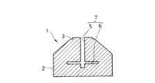
図中、1はアンビルであり、該アンビル1は、アンビル、アンビルホルダーの重量、サイズに制約がある自動溶着機等におけるアンビルである。
In the figure,
また、該アンビル1は、その本体2の頂部に溶着突起部3が設けられ、また該溶着突起部3の上面には突条4が形成されている。また、該アンビル1は、その本体2における溶着突起部3の真下に、該溶着突起部3の中央からアンビル本体2の略中心部まで真下に延びる縦スリット5と、該縦スリット5の下端近傍においてこれと十字状に直交する横スリット6とからなるスリット7を設け、該溶着突起部3及びその下側部分がホーンの振動ベクトルと略平行した方向に撓み得るようになしている。尚、図において、8はホーン、Wは溶着するため重ねた、夫々の厚味が50μm以下の超極薄プラスチックフィルム9、10からなるワークである。
The
本実施形態によれば、溶着中のアンビル本体2における溶着突起部3及びその下側部分に、図5に示す如き撓み振動が発生するものである。そしてこれにより、図6乃至図8に示す如く、アンビル1における斯かる部分の振動にひずみが生ずることがないものである。したがって、アンビル、アンビルホルダーの重量、サイズに制約がある自動溶着機等におけるアンビル1において、アンビル1の振動とホーン8の振動とがワークWを通して衝突を起こすことがないものである。尚、図5は振動を一方向で示しているが、実際は往復運動するものであり、また図6乃至図8において、Aは図3におけるホーン7の先端A部分における振動、Bは図3におけるアンビル1の上端B部分における振動を示すものである。
According to this embodiment, the bending vibration as shown in FIG. 5 is generated in the
次に、図9及び図10に示す本発明の第2実施形態について説明する。 Next, a second embodiment of the present invention shown in FIGS. 9 and 10 will be described.
本実施形態と前記第1実施形態とは、前記第1実施形態におけるスリットに代えて、本実施形態において空洞としたことにある。 The present embodiment and the first embodiment are that a cavity is used in this embodiment instead of the slit in the first embodiment.
即ち、本実施形態は、アンビル本体2における溶着突起部3の真下におけるアンビル本体2の略中心部に、円形の空洞11を設けてなるものである。そして、これにより溶着突起部3及びその下側部分がホーン8の振動ベクトルと略平行した方向に撓み得るようになしたものである。したがって、図10に示す如き撓み振動が発生し、前記第1実施形態におけると同様にアンビル1の溶着突起部3及びその下側部分の振動にひずみが生ずることがないものである。
That is, in the present embodiment, a
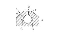
次に、図11及び図12に示す本発明の第3実施形態について説明する。 Next, a third embodiment of the present invention shown in FIGS. 11 and 12 will be described.
本実施形態と前記第1実施形態とは、本実施形態において前記第1実施形態におけるスリットと前記第2実施形態における空洞とを合わせた形態とした点において相違するものである。 This embodiment is different from the first embodiment in that the slit in the first embodiment and the cavity in the second embodiment are combined in the present embodiment.
即ち、本実施形態は、アンビル本体2における溶着突起部3の真下に、該溶着突起部3の真下におけるアンビル本体2の略中心部に設けた円形の空洞12と、該溶着突起部3の中央から前記円形の空洞12まで真下に延びる縦スリット13と、前記円形の空洞12から左右に延びる横スリット14、15とを設けてなるものである。そして、これにより溶着突起部3及びその下側部分がホーン8の振動ベクトルと略平行した方向に撓み得るようになしたものである。したがって、図12に示す如き撓み振動が発生し、前記第1実施形態におけると同様にアンビル1の溶着突起部3及びその下側部分の振動にひずみが生ずることがないものである。
That is, in the present embodiment, a
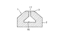
次に、図13及び図14に示す本発明の第4実施形態について説明する。 Next, a fourth embodiment of the present invention shown in FIGS. 13 and 14 will be described.
本実施形態と前記第1実施形態とは、本実施形態において前記第1実施形態におけるスリットと前記第2実施形態における空洞とを合わせた形態とした点において相違するものである。 This embodiment is different from the first embodiment in that the slit in the first embodiment and the cavity in the second embodiment are combined in the present embodiment.
即ち、本実施形態は、アンビル本体2における溶着突起部3の真下に、該溶着突起部3の真下におけるアンビル本体2の略中心部に設けた、底辺の左右から斜辺にかけて僅かな垂直部分を有する略三角形状の空洞16と、該溶着突起部3の中央から前記略三角形状の空洞16まで真下に延びる縦スリット17とを設けてなるものである。そして、これにより溶着突起部3及びその下側部分がホーン8の振動ベクトルと略平行した方向に撓み得るようになしたものである。したがって、図14に示す如き撓み振動が発生し、前記第1実施形態におけると同様にアンビル1の溶着突起部3及びその下側部分の振動にひずみが生ずることがないものである。
That is, this embodiment has a slight vertical portion from the right and left of the bottom side to the oblique side, which is provided at a substantially central portion of the
1 アンビル
2 アンビル本体
3 溶着突起部
4 突条
5 縦スリット
6 横スリット
7 スリット
11 円形の空洞
12 円形の空洞
13 縦スリット
14、15 横スリット
16 略三角形状の空洞
17 縦スリット
DESCRIPTION OF
Claims (5)
The slit and the cavity are provided at a substantially central portion of the anvil body directly below the welding projection, and have a substantially triangular cavity having a slight vertical portion from the left and right sides to the hypotenuse, and the center of the welding projection. The ultrasonic welding anvil according to claim 1, wherein the anvil is a vertical slit extending directly down to a substantially triangular cavity.
Priority Applications (1)
| Application Number | Priority Date | Filing Date | Title |
|---|---|---|---|
| JP2013182727A JP2015047629A (en) | 2013-09-04 | 2013-09-04 | Anvil for ultrasonic welding |
Applications Claiming Priority (1)
| Application Number | Priority Date | Filing Date | Title |
|---|---|---|---|
| JP2013182727A JP2015047629A (en) | 2013-09-04 | 2013-09-04 | Anvil for ultrasonic welding |
Publications (1)
| Publication Number | Publication Date |
|---|---|
| JP2015047629A true JP2015047629A (en) | 2015-03-16 |
Family
ID=52698100
Family Applications (1)
| Application Number | Title | Priority Date | Filing Date |
|---|---|---|---|
| JP2013182727A Pending JP2015047629A (en) | 2013-09-04 | 2013-09-04 | Anvil for ultrasonic welding |
Country Status (1)
| Country | Link |
|---|---|
| JP (1) | JP2015047629A (en) |
Cited By (2)
| Publication number | Priority date | Publication date | Assignee | Title |
|---|---|---|---|---|
| JP2020040297A (en) * | 2018-09-11 | 2020-03-19 | 株式会社シルキー・アクト | Resin sheet joining apparatus, resin sheet joined article manufacturing apparatus, and resin sheet joined article manufacturing method |
| JP2021017044A (en) * | 2019-07-24 | 2021-02-15 | Asti株式会社 | Ultrasonic stapler, resin pins for ultrasonic stapler, and bundling method with resin pins |
Citations (2)
| Publication number | Priority date | Publication date | Assignee | Title |
|---|---|---|---|---|
| JP2001522321A (en) * | 1997-02-21 | 2001-11-13 | テトラ ラバル ホールデイングス エ フイナンス ソシエテ アノニム | Ultrasonic sealing anvil |
| JP2012024790A (en) * | 2010-07-21 | 2012-02-09 | Yazaki Corp | Ultrasonic welding device |
-
2013
- 2013-09-04 JP JP2013182727A patent/JP2015047629A/en active Pending
Patent Citations (2)
| Publication number | Priority date | Publication date | Assignee | Title |
|---|---|---|---|---|
| JP2001522321A (en) * | 1997-02-21 | 2001-11-13 | テトラ ラバル ホールデイングス エ フイナンス ソシエテ アノニム | Ultrasonic sealing anvil |
| JP2012024790A (en) * | 2010-07-21 | 2012-02-09 | Yazaki Corp | Ultrasonic welding device |
Cited By (3)
| Publication number | Priority date | Publication date | Assignee | Title |
|---|---|---|---|---|
| JP2020040297A (en) * | 2018-09-11 | 2020-03-19 | 株式会社シルキー・アクト | Resin sheet joining apparatus, resin sheet joined article manufacturing apparatus, and resin sheet joined article manufacturing method |
| JP2021017044A (en) * | 2019-07-24 | 2021-02-15 | Asti株式会社 | Ultrasonic stapler, resin pins for ultrasonic stapler, and bundling method with resin pins |
| JP7339048B2 (en) | 2019-07-24 | 2023-09-05 | Asti株式会社 | Ultrasonic staplers and resin pins for ultrasonic staplers |
Similar Documents
| Publication | Publication Date | Title |
|---|---|---|
| JP5400246B1 (en) | Speaker and its edge structure | |
| JP6355255B2 (en) | Vibration isolator | |
| JP6484909B2 (en) | Ultrasonic horn | |
| JP2017019386A5 (en) | ||
| JP2015047629A (en) | Anvil for ultrasonic welding | |
| JP2016107737A (en) | Energy absorption structure for vehicle | |
| JP3183392U (en) | Round speaker structure | |
| JP2019034316A (en) | Ultrasonic joint jig, ultrasonic joining method, and joint structure | |
| JP4188182B2 (en) | Speaker | |
| JP2018004994A (en) | Snare wire and snare drum | |
| JP6279024B2 (en) | Ultrasonic welding anvil | |
| CN104826786A (en) | Flange type ultrasonic transducer | |
| CN105312216B (en) | A kind of light-duty high rigidity ultrasonic transducer | |
| JP7121492B2 (en) | Vibration damping sheet and its installation method | |
| JP2012024790A (en) | Ultrasonic welding device | |
| JP2009029336A (en) | Jack-up bracket | |
| JP2009041610A (en) | Dynamic damper | |
| JP3155810U (en) | Vibration absorbing structure | |
| JP2015217817A (en) | bracket | |
| JP2012210576A (en) | Ultrasonic transducer | |
| JP5772075B2 (en) | Vibration welding equipment | |
| JP2014073491A (en) | Sonotrode holder | |
| JP2015221451A (en) | Manufacturing method of welded structure | |
| JP2014162165A (en) | Supersonic deposition apparatus, and production method of deposition product | |
| JP2015204269A (en) | electromagnetic contactor |
Legal Events
| Date | Code | Title | Description |
|---|---|---|---|
| A621 | Written request for application examination |
Free format text: JAPANESE INTERMEDIATE CODE: A621 Effective date: 20150422 |
|
| A131 | Notification of reasons for refusal |
Free format text: JAPANESE INTERMEDIATE CODE: A131 Effective date: 20160322 |
|
| A977 | Report on retrieval |
Free format text: JAPANESE INTERMEDIATE CODE: A971007 Effective date: 20160324 |
|
| A02 | Decision of refusal |
Free format text: JAPANESE INTERMEDIATE CODE: A02 Effective date: 20161018 |