JP2015046830A - Image forming device - Google Patents
Image forming device Download PDFInfo
- Publication number
- JP2015046830A JP2015046830A JP2013178099A JP2013178099A JP2015046830A JP 2015046830 A JP2015046830 A JP 2015046830A JP 2013178099 A JP2013178099 A JP 2013178099A JP 2013178099 A JP2013178099 A JP 2013178099A JP 2015046830 A JP2015046830 A JP 2015046830A
- Authority
- JP
- Japan
- Prior art keywords
- antenna
- unit
- image forming
- operation unit
- forming apparatus
- Prior art date
- Legal status (The legal status is an assumption and is not a legal conclusion. Google has not performed a legal analysis and makes no representation as to the accuracy of the status listed.)
- Granted
Links
Images


Abstract
Description
本発明は、画像形成装置に関するものである。 The present invention relates to an image forming apparatus.
近年、電子機器の無線LAN化が進んでおり、画像形成装置においてもアンテナを設けて画像情報等の無線のやり取りが行われている。特許文献1には、このようなアンテナを備える画像形成装置が開示されている。この画像形成装置においては、プリンタユニットの背面側に制御ユニットを有し、この制御ユニットにアンテナが設けられている(特許文献1の図9及び図10参照)。
2. Description of the Related Art In recent years, wireless LAN of electronic devices has been advanced, and an image forming apparatus is provided with an antenna to exchange image information and the like wirelessly.
ところで、画像形成装置のような大型の産業機械においては、装置本体の背面側に機械的な駆動機構(給紙機構や現像機構の回転軸)を支えるための金属フレームを有している場合が多く、上記従来技術の制御ユニットもこの金属フレームに支えられているものと考えられる。
しかしながら、電波の波長より十分大きな金属フレームを有している大型機械に、無線LANのアンテナを接続する場合には、その金属フレームにより装置本体自体が電波の遮蔽物となってしまう場合がある。この場合、例えば装置本体の上面にアンテナを設置し、設置場所の天井にアクセスポイントを配置することによって改善することが考えられる。しかし、複合機等においては、上面は自動原稿送り装置(ADF)等の開閉操作をするため可動する部分となっており、装置本体の上面に外部アンテナを取り付けることができない、といった制約がある。
By the way, a large-scale industrial machine such as an image forming apparatus may have a metal frame for supporting a mechanical driving mechanism (a rotation shaft of a paper feeding mechanism or a developing mechanism) on the back side of the apparatus main body. Many of the above prior art control units are also believed to be supported by this metal frame.
However, when a wireless LAN antenna is connected to a large machine having a metal frame sufficiently larger than the wavelength of the radio wave, the apparatus body itself may become a radio wave shield due to the metal frame. In this case, for example, it is conceivable to improve by installing an antenna on the upper surface of the apparatus body and arranging an access point on the ceiling of the installation location. However, in a multifunction machine or the like, the upper surface is a movable part for opening and closing an automatic document feeder (ADF) or the like, and there is a restriction that an external antenna cannot be attached to the upper surface of the apparatus body.
本発明は、上記問題点に鑑みてなされたものであり、アンテナの送受信性能を向上させることができる画像形成装置を提供することを目的とする。 SUMMARY An advantage of some aspects of the invention is that it provides an image forming apparatus capable of improving the transmission / reception performance of an antenna.
上記の課題を解決するために、本発明は、装置本体の前面側に操作部が設けられている画像形成装置であって、外部と通信するアンテナ部が、前記操作部に設けられている、という構成を採用する。
この構成を採用することによって、本発明では、装置本体の前面側に設けられている操作部にアンテナ部があるため、装置本体の背面側にある金属フレームによる電波遮蔽の影響を低減できる。また、装置本体の前面側は、通常、駆動機構をメンテナンス等するときに大きく可動する開閉扉があり、取り付けの制約があるが、操作部であればこのような制約はない。
In order to solve the above-described problem, the present invention provides an image forming apparatus in which an operation unit is provided on the front side of the apparatus main body, and an antenna unit that communicates with the outside is provided in the operation unit. The configuration is adopted.
By adopting this configuration, in the present invention, since the operation unit provided on the front side of the apparatus main body has an antenna unit, the influence of radio wave shielding by the metal frame on the back side of the apparatus main body can be reduced. In addition, the front side of the apparatus main body usually has an opening / closing door that is largely movable when performing maintenance or the like on the drive mechanism, and there are restrictions on attachment, but there is no such restriction as long as it is an operation unit.
また、本発明では、前記アンテナ部は、前記操作部において互いに異なる位置に設けられた第1アンテナ及び第2アンテナを有する、という構成を採用する。
この構成を採用することによって、本発明では、電波状況(例えば、電波強度)に応じて位置が異なる第1アンテナ及び第2アンテナを使い分けることができる。
In the present invention, a configuration is adopted in which the antenna unit includes a first antenna and a second antenna provided at different positions in the operation unit.
By adopting this configuration, in the present invention, it is possible to selectively use the first antenna and the second antenna whose positions differ depending on the radio wave condition (for example, radio wave intensity).
また、本発明では、前記第1アンテナ及び第2アンテナは、前記操作部において互いに異なる向きで設けられている、という構成を採用する。
この構成を採用することによって、本発明では、電波状況(例えば、電波の指向性)に応じて向きが異なる第1アンテナ及び第2アンテナを使い分けることができる。
Further, the present invention employs a configuration in which the first antenna and the second antenna are provided in different directions in the operation unit.
By adopting this configuration, in the present invention, it is possible to selectively use the first antenna and the second antenna having different directions depending on the radio wave condition (for example, the directivity of the radio wave).
また、本発明では、前記第1アンテナ及び前記第2アンテナのいずれか一方から前記通信を行わせるアンテナ切替部を有する、という構成を採用する。
この構成を採用することによって、本発明では、アンテナ切替部があることで設置場所周辺の電波状況に応じて、操作部におけるアンテナ位置を切り替えることができる。
Further, the present invention employs a configuration in which an antenna switching unit that allows the communication to be performed from one of the first antenna and the second antenna is employed.
By adopting this configuration, in the present invention, since the antenna switching unit is provided, the antenna position in the operation unit can be switched according to the radio wave condition around the installation location.
また、本発明では、前記操作部の水平面に対する角度を調整する角度調整部を有する、という構成を採用する。
この構成を採用することによって、本発明では、アンテナ部を設けた操作部の水平面に対する角度を調整することができる。
Moreover, in this invention, the structure of having an angle adjustment part which adjusts the angle with respect to the horizontal surface of the said operation part is employ | adopted.
By adopting this configuration, in the present invention, the angle with respect to the horizontal plane of the operation unit provided with the antenna unit can be adjusted.
また、本発明では、前記操作部の前記角度に応じて、前記アンテナ切替部を動作させる制御部を有する、という構成を採用する。
この構成を採用することによって、本発明では、操作部の水面に対する角度の調整により、例えば電波強度が第1アンテナよりも第2アンテナの方が有利になった場合には、自動的に第2アンテナにアンテナ位置を切り替えることができる。
Moreover, in this invention, the structure of having a control part which operates the said antenna switching part according to the said angle of the said operation part is employ | adopted.
By adopting this configuration, the present invention automatically adjusts the angle of the operation unit with respect to the water surface, for example, when the radio wave strength becomes more advantageous for the second antenna than the first antenna. The antenna position can be switched to the antenna.
また、本発明では、前記アンテナ部は、前記操作部の操作キー基板にパターニングされたマイクロストリップアンテナを有する、という構成を採用する。
この構成を採用することによって、本発明では、操作キー基板にアンテナが一体的に形成されるため、アンテナに関する部品点数を削減し、部品コスト・組み立て工数を削減することができる。
In the present invention, the antenna section has a microstrip antenna patterned on the operation key board of the operation section.
By adopting this configuration, in the present invention, since the antenna is integrally formed on the operation key board, the number of parts related to the antenna can be reduced, and the part cost and the number of assembly steps can be reduced.
本発明によれば、アンテナの送受信性能を向上させることができる画像形成装置が得られる。 According to the present invention, an image forming apparatus capable of improving the transmission / reception performance of an antenna is obtained.
以下、図面を参照しながら、本発明の一実施形態について説明する。なお、以下では、本発明に係る画像形成装置として、コピー機、プリンター及びファクシミリ等の機能を併せ持つ複合機を例示して説明する。 Hereinafter, an embodiment of the present invention will be described with reference to the drawings. Hereinafter, as an image forming apparatus according to the present invention, a multifunction machine having functions such as a copier, a printer, and a facsimile will be described as an example.
(第1実施形態)
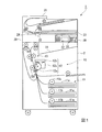
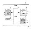
図1は、本発明の第1実施形態における複合機1の要部構成を示す正面透視図である。図2は、本発明の第1実施形態における複合機1の機能ブロック図である。これらの図に示すように、複合機1は、印刷部(画像形成部)10と、原稿読取部20と、操作部30と、通信部40と、制御部50とを備えている。印刷部10、通信部40及び制御部50は、装置本体2の内部に収容されている。また、原稿読取部20は、装置本体2の上面側に設けられている。また、操作部30は、装置本体2の前面側に設けられている。
(First embodiment)
FIG. 1 is a front perspective view showing the main configuration of a
印刷部10は、制御部50による制御の下、印刷用紙に画像を印刷して印刷物として出力するものであり、給紙部11、トナー画像形成部12、定着部13及び排紙トレイ14等を備えている。給紙部11は、定型の印刷用紙を複数枚(例えば、数十枚程度)収容可能であると共に、複合機1の正面から引出し可能な給紙カセット11aを複数備えている。給紙カセット11aの各々に収容された印刷用紙のうちの最上位の印刷用紙は、ピックアップローラー11bの駆動によって繰り出されてトナー画像形成部12へ搬送される。
The
トナー画像形成部12は、印刷すべき画像に応じたトナー画像を印刷用紙に形成するものであり、感光体ドラム12a、露光部12b、現像部12c及び転写部12d等を備えている。感光体ドラム12aは、印刷すべき画像に応じた静電潜像が形成されると共に、現像されたトナー画像を担持する円筒形の感光体である。露光部12bは、感光体ドラム12aの表面に静電潜像を形成するためのレーザー光を感光体ドラム12aに照射する。現像部12cは、静電潜像が形成された感光体ドラム12aにトナーを供給することにより、静電潜像を現像してトナー画像にする。転写部12dは、感光体ドラム12aに担持されているトナー画像を、給紙部11から搬送されてきた印刷用紙に転写する。
The toner
定着部13は、トナー画像形成部12によって印刷用紙に転写(形成)されたトナー画像を加熱及び加圧して印刷用紙に定着させた後、当該定着処理後の印刷用紙を所望の画像が印刷された印刷物として排紙トレイ14へ排出(出力)する。排紙トレイ14は、定着部13から出力される印刷物を溜め置きするための部位であり、印刷部10の上部に設けられている。
The
原稿読取部20は、制御部50による制御の下、ユーザーにセットされた原稿を読み取り、その原稿の画像(原稿画像)を示す原稿画像データを生成して制御部50に出力するものであり、ADF(自動原稿送り装置)21、キャリッジ22、原稿台23及び原稿読取スリット24等を備えている。ADF21は、読み取りを行うべき原稿を順次自動給紙する装置である。キャリッジ22は、露光ランプ及びCCD(Charge Coupled Device)センサー等を搭載しており、ADF21によって順次給紙される原稿、或いは原稿台23にセットされた原稿を読み取る。
The
具体的に、原稿台23にセットされた原稿を読み取る場合には、キャリッジ22は、原稿台23の長手方向に移動しながらCCDセンサーにより原稿を読み取る。これに対し、ADF21から給紙される原稿を読み取る場合には、キャリッジ22は、原稿読取スリット24に対向する位置(原稿読取スリット24の下方の位置)において、ADF21から順次給紙される原稿を、原稿読取スリット24を介してCCDセンサーにより読み取る。
Specifically, when reading a document set on the document table 23, the
操作部30は、ユーザーによる操作に応じた信号(操作信号)を制御部50に出力すると共に、制御部50による制御に応じて複合機1の状態を示す情報等の各種情報を表示するものであり、操作キー31及び操作表示部32を備えている。操作キー31は、コピースタートキー、コピーストップ/クリアキー、テンキー(数値入力キー)及び機能切替キー等のハードキーである。なお、機能切替キーとは、複合機1で実現されるコピー機能、プリント機能、スキャン機能及びファクシミリ機能の各々をユーザーが使用する場合に、各機能の動作モードへ複合機1を切り替える為のキーである。
The
操作表示部32は、制御部50による制御の下、所定の画像を表示するディスプレイと、このディスプレイの表示画面上で為された操作に応じた操作信号を制御部50に出力する位置入力装置とを備えている。なお、ディスプレイは、例えば液晶パネル或いは有機ELパネルである。また、位置入力装置は、例えばディスプレイの表示画面に対向配置されたタッチパネルであり、上記操作信号としてユーザーに押下された部位の座標を示す信号を出力する。
The
通信部40は、相手先ファクシミリやパーソナルコンピューター等の外部機器との通信を行うものであり、有線通信部41及びアンテナ部(無線通信部)42を備える。有線通信部41は、例えば、公衆電話回線に接続されて相手先ファクシミリとの間で通信を行う。アンテナ部42は、例えば、無線LAN(Local Area Network)アンテナを備えて、LANに接続されたアクセスポイントを介して、同じくLANに接続されたパーソナルコンピューター等の端末装置との間で通信を行う。
The
制御部50は、操作部30から入力された操作信号、及び通信部40を介して外部機器から受信した信号に基づいて、複合機1の全体動作を統括制御する。制御部50は、内部メモリ、CPU(Central Processing Unit)、及び他の各部とのデータ授受を行う各種入出力インターフェース回線等から構成される。
The
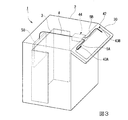
図3は、本発明の第1実施形態における装置本体2に対する操作部30とアンテナ部42と制御部50との配置を説明するための図である。
図3に示すように、制御部50は、装置本体2の背面側に配置されている。装置本体2の背面側には、上述した印刷部10の給紙機構や現像機構の回転軸を支えるための金属プレート3が設けられている。制御部50は、この金属プレート3の背面側に設けられている。
FIG. 3 is a diagram for explaining the arrangement of the
As shown in FIG. 3, the
装置本体2では、金属プレート3やその他必要な強度部材以外の部分(例えば外部筐体)が、軽量化、低コスト化等の理由によりプラスチックによって形成されている。操作部30の部分についてもこのような理由により、プラスチックで外部筐体が形成されている。図3に示すように、操作部30は、装置本体2の前面側に配置されている。アンテナ部42は、装置本体2の前面側に配置された操作部30の筐体内部に設けられている。アンテナ部42は、装置本体2の背面側から前面側に渡って配線された同軸ケーブル4によって、制御部50と接続されている。
In the apparatus
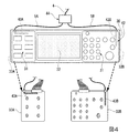
図4は、本発明の第1実施形態における操作部30に設けられたアンテナ部42の構成図である。
図4に示すように、アンテナ部42は、操作部30の外部筐体の中に設けられた第1アンテナ43A及び第2アンテナ43Bを有する。第1アンテナ43A及び第2アンテナ43Bは、マイクロストリップアンテナである。第1アンテナ43Aは、操作キー31の機能切替キーの操作キー基板33Aにパターニングされている。また、第2アンテナ43Bは、操作キー31のテンキーの操作キー基板33Bにパターニングされている。
FIG. 4 is a configuration diagram of the
As shown in FIG. 4, the
第1アンテナ43A及び第2アンテナ43Bは、操作部30において互いに異なる位置に設けられている。具体的には、第1アンテナ43Aが、操作表示部32を挟んだ一方側(図4において右側)に配置された操作キー基板33Aに設けられており、第2アンテナ43Bが、操作表示部32を挟んだ他方側(図4において左側)に配置された操作キー基板33Bに設けられている。また、第1アンテナ43Aは、操作キー基板33Aの左寄りにパターニングされており、第2アンテナ43Bは、操作キー基板33Aの右寄りにパターニングされている。
The
また、第1アンテナ43A及び第2アンテナ43Bは、操作部30において互いに異なる向きで設けられている。具体的には、第1アンテナ43Aが、操作キー基板33Aにおいて操作部30の長手方向(図4において左右方向)に沿って延在して設けられており、第2アンテナ43Bが、操作キー基板33Bにおいて操作部30の短手方向(図4において上下方向)に沿って延在して設けられている。
このように、第1アンテナ43A及び第2アンテナ43Bは、操作部30においてできるだけ離間するように設けられ、且つ、互いに直交する向きで設けられている。
The
Thus, the
本実施形態では、第1アンテナ43A及び第2アンテナ43Bのいずれか一方から通信を行わせるアンテナ切替部44が設けられている。アンテナ切替部44は、同軸ケーブル5Aを介して第1アンテナ43Aと接続され、また、同軸ケーブル5Bを介して第2アンテナ43Bと接続され、さらに、同軸ケーブル4を介して制御部50と接続されている。アンテナ切替部44は、同軸ケーブル4に対する接続を、同軸ケーブル5Aあるいは同軸ケーブル5Bに切り替えることで、第1アンテナ43A及び第2アンテナ43Bのいずれか一方から通信を行わせるようになっている。
In the present embodiment, an
図5は、本発明の第1実施形態におけるアンテナ切替部44の構成図である。
図5に示すように、アンテナ切替部44は、回転式切替器45と、切替用レバー46と、を有する。回転式切替器45は、同軸ケーブル4,5A,5Bが接続される固定部47と、導波路を同軸ケーブル5A,5Bに切り替えるための回転部48と、を有する。回転部48は、円柱状になっており、固定部47に対してその中心軸周りに回転可能に設けられている。この回転部48には、同軸ケーブル4,5Aを接続するための配線49Aと、同軸ケーブル4,5Bを接続するための配線49Bと、が設けられている。
FIG. 5 is a configuration diagram of the
As shown in FIG. 5, the
切替用レバー46は、一端部が回転部48に接続されている押し引きレバーである。切替用レバー46の一端部は、回転部48の中心軸から離間した位置に接続されており、レバーの押し引きにより回転部48に回転トルクを与えることができるようになっている。一方、切替用レバー46の他端部は、操作部30の外部筐体から突出しており、ユーザーが操作可能となっている。本実施形態では、図5(a)に示すように切替用レバー46を押し込んだときに、同軸ケーブル4,5Bが接続されて導波路が第2アンテナ43Bに切り替えられ、一方で、図5(b)に示すように切替用レバー46を引き出したときに、同軸ケーブル4,5Aが接続されて導波路が第1アンテナ43Aに切り替えられる。
The switching
続いて、上記構成の複合機1における無線LAN通信に係る作用について説明する。
Next, an operation related to wireless LAN communication in the
複合機1においては、図3に示すように、主たる画像処理や入出力インターフェースを制御する制御部50が、装置本体2の背面側に配置されている。複合機1のように、装置本体2が大きいものは、印刷部10の給紙機構や現像機構の回転軸を支えるための金属プレート3が背面側に設けられており、それが電波遮蔽物となって、電波指向性が制約される可能性がある。このため、本実施形態の複合機1では、制御部50のトランシーバー回路に接続するアンテナ部42については、装置本体2の背面側から同軸ケーブル4にて引き出し、電波遮蔽物(金属プレート3)から離れた位置に配置している。
In the
本実施形態では、装置本体2の前面側に操作部30が設けられており、外部と通信するアンテナ部42が、操作部30に設けられている。この構成によれば、装置本体2の前面側に設けられている操作部30にアンテナ部42があるため、装置本体2の背面側にある金属プレート3による電波遮蔽の影響を低減できる。また、装置本体2の前面側は、通常、駆動機構をメンテナンス等するときに大きく可動する開閉扉があり取り付けの制約があるが、操作部30であればこのような制約はない。さらに、操作部30にアンテナ部42を内蔵することで、複合機1の外観を損ねずに、機器内部にアンテナ部42を配置することができる。
In the present embodiment, the
また、アンテナ部42は、図4に示すように、操作部30の操作キー基板33A,33Bにパターニングされたマイクロストリップアンテナ(第1アンテナ43A及び第2アンテナ43B)を有する。この構成によれば、操作キー基板33A,33Bにアンテナが一体的に形成されるため、アンテナに関する部品点数を削減し、部品コスト・組み立て工数を削減することができる。また、複合機1の構造的に電波遮蔽する金属部分が少ない、すなわち外部筐体及び操作キー基板33A,33Bが樹脂製の操作部30に、アンテナを内蔵することによって、安価な構造のアンテナパターンでも、送受信性能を向上できる。
As shown in FIG. 4, the
また、本実施形態では、第1アンテナ43A及び第2アンテナ43Bのいずれか一方から通信を行わせるアンテナ切替部44を有する。この構成によれば、アンテナ切替部44があることで設置場所周辺の電波状況に応じて、操作部30におけるアンテナ位置を切り替えることができる。本実施形態のアンテナ切替部44によれば、切替用レバー46を押し引きすることで、操作部30の左右に配置した第1アンテナ43A及び第2アンテナ43Bのどちらかに切り替えることができる。
Moreover, in this embodiment, it has the
したがって、複合機1では、電波状況(例えば、電波強度や電波の指向性)に応じて、位置が異なる第1アンテナ43A及び第2アンテナ43Bを使い分け、また、向きが異なる第1アンテナ43A及び第2アンテナ43Bを使い分けることができる。このように、複合機1は、装置本体2が大きく金属部分が多いため、操作部30に複数のアンテナを内蔵し、これを容易切り替えられるようにしておくことで、設置場所に適した受信性能を得る事ができる。すなわち、内蔵アンテナの位置を容易な操作で変更でき、複合機1の設置場所を変更せずともLANのアクセスポイントとの位置関係に応じた電波強度・指向性が得られるようになる。
Therefore, in the
このように、上述の本実施形態によれば、装置本体2の前面側に操作部30が設けられている複合機1であって、外部と通信するアンテナ部42が、操作部30に設けられている、という構成を採用することによって、アンテナの送受信性能を向上させることができる複合機1が得られる。
As described above, according to the above-described embodiment, the
(第2実施形態)
次に、本発明の第2実施形態について説明する。以下の説明において、上述の実施形態と同一又は同等の構成部分については同一の符号を付し、その説明を簡略若しくは省略する。
(Second Embodiment)
Next, a second embodiment of the present invention will be described. In the following description, the same or equivalent components as those of the above-described embodiment are denoted by the same reference numerals, and the description thereof is simplified or omitted.
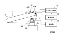
図6は、本発明の第2実施形態における操作部30の側面図である。図7は、本発明の第2実施形態におけるアンテナ切替部44の構成図である。
図6及び図7に示すように、第2実施形態では、操作部30の水平面に対する角度θに応じて、アンテナ切替部44を動作させる制御部50を有する点で、上記実施形態と異なる。
FIG. 6 is a side view of the
As shown in FIGS. 6 and 7, the second embodiment is different from the above embodiment in that it includes a
第2実施形態では、図6に示すように、操作部30の水平面に対する角度θを調整する角度調整部60を有する。角度調整部60は、操作部30に設けられた水平方向に延在する回転軸61と、装置本体2に設けられて回転軸61を回転自在に支持する軸受部62と、を有する。このように、第2実施形態の操作部30は、ユーザーによって使用しやすい任意の角度θに調整可能となっている。
In 2nd Embodiment, as shown in FIG. 6, it has the
ところで、ユーザーが操作しやすい配慮のために操作部30の角度θを変更すると、アクセスポイントの位置によっては電波強度や電波の指向性が変化することもあり、例えば、角度調整前の第1アンテナ43Aよりも第2アンテナ43Bの方が送受信性能について有利になる場合がある。そのため、第2実施形態の制御部50は、操作部30の角度調整に伴い送受信性能の有利な方にアンテナ接続を自動的に切り替えるようになっている。
By the way, when the angle θ of the
制御部50は、図7に示すように、角度検出センサー51によって操作部30の角度θを検出し、当該検出結果に基づいて駆動装置52を駆動させ、アンテナ切替部44を操作するように構成されている。角度検出センサー51としては、操作部30の回転軸61の回転角度を検出するロータリーエンコーダーや、重力方向を検出することにより操作部30の角度を検出する多軸加速度センサー等を採用することができる。また、駆動装置52としては、ラックピニオン構造やボールネジ構造等を採用し、切替用レバー46をモーターで駆動させるもの等が採用できる。
As shown in FIG. 7, the
制御部50は、操作部30の角度θと、その角度θに対応する第1アンテナ43A、第2アンテナ43Bの送受信性能の強弱についての対応関係を予め実験等で計測し、その対応関係を規定したテーブルデータを内部メモリに記憶している。このため、制御部50は、角度検出センサー51の検出結果を当該テーブルデータと照合し、その照合に基づいて駆動装置52を介して切替用レバー46を操作し、送受信性能の有利な方にアンテナ接続を切り替えるようにアンテナ切替部44を動作させる。
The
このような第2実施形態によれば、操作部30に角度調整部60により角度調整可能な場合であっても、操作部30の水面に対する角度θの調整により、例えば電波強度が第1アンテナ43Aよりも第2アンテナ43Bの方が有利になった場合には、自動的に第2アンテナ43Bにアンテナ位置を切り替えることができる。したがって、第2実施形態によれば、ユーザーが操作部30の角度調整した場合であっても、切替用レバー46を操作せず自動的にLANのアクセスポイントとの位置関係に応じた電波強度・指向性が得られるようになり、ユーザーの操作により適したものとなる。
According to the second embodiment as described above, even if the angle of the
以上、図面を参照しながら本発明の好適な実施形態について説明したが、本発明は上記実施形態に限定されるものではない。上述した実施形態において示した各構成部材の諸形状や組み合わせ等は一例であって、本発明の主旨から逸脱しない範囲において設計要求等に基づき種々変更可能である。 As mentioned above, although preferred embodiment of this invention was described referring drawings, this invention is not limited to the said embodiment. Various shapes, combinations, and the like of the constituent members shown in the above-described embodiments are examples, and various modifications can be made based on design requirements and the like without departing from the gist of the present invention.
例えば、上記実施形態では、本発明に係る画像形成装置として複合機1を参照しながら説明したが、本発明はこれに限定されず、コピー機などの他の画像形成装置に適用することができる。 For example, in the above-described embodiment, the image forming apparatus according to the present invention has been described with reference to the multifunction peripheral 1, but the present invention is not limited to this and can be applied to other image forming apparatuses such as a copying machine. .
1…複合機(画像形成装置)、2…装置本体、30…操作部、33A…操作キー基板、33B…操作キー基板、42…アンテナ部、43A…第1アンテナ、43B…第2アンテナ、44…アンテナ切替部、50…制御部、60…角度調整部
DESCRIPTION OF
Claims (7)
外部と通信するアンテナ部が、前記操作部に設けられている、ことを特徴とする画像形成装置。 An image forming apparatus in which an operation unit is provided on the front side of the apparatus main body,
An image forming apparatus, wherein an antenna unit that communicates with the outside is provided in the operation unit.
Priority Applications (1)
| Application Number | Priority Date | Filing Date | Title |
|---|---|---|---|
| JP2013178099A JP6027954B2 (en) | 2013-08-29 | 2013-08-29 | Image forming apparatus |
Applications Claiming Priority (1)
| Application Number | Priority Date | Filing Date | Title |
|---|---|---|---|
| JP2013178099A JP6027954B2 (en) | 2013-08-29 | 2013-08-29 | Image forming apparatus |
Publications (2)
| Publication Number | Publication Date |
|---|---|
| JP2015046830A true JP2015046830A (en) | 2015-03-12 |
| JP6027954B2 JP6027954B2 (en) | 2016-11-16 |
Family
ID=52671997
Family Applications (1)
| Application Number | Title | Priority Date | Filing Date |
|---|---|---|---|
| JP2013178099A Expired - Fee Related JP6027954B2 (en) | 2013-08-29 | 2013-08-29 | Image forming apparatus |
Country Status (1)
| Country | Link |
|---|---|
| JP (1) | JP6027954B2 (en) |
Cited By (6)
| Publication number | Priority date | Publication date | Assignee | Title |
|---|---|---|---|---|
| JP2016221765A (en) * | 2015-05-28 | 2016-12-28 | 富士ゼロックス株式会社 | Image formation device |
| JP2017001335A (en) * | 2015-06-12 | 2017-01-05 | サトーホールディングス株式会社 | Printing device |
| CN106353981A (en) * | 2015-07-14 | 2017-01-25 | 佳能株式会社 | Image forming apparatus |
| JP2017154374A (en) * | 2016-03-02 | 2017-09-07 | 京セラドキュメントソリューションズ株式会社 | Image formation device |
| JP2019155857A (en) * | 2018-03-16 | 2019-09-19 | 株式会社リコー | Display operation part and image forming apparatus |
| US10785378B2 (en) | 2018-03-16 | 2020-09-22 | Ricoh Company, Ltd. | Display-and-operation device and image forming apparatus |
Citations (5)
| Publication number | Priority date | Publication date | Assignee | Title |
|---|---|---|---|---|
| JPH11338317A (en) * | 1998-05-28 | 1999-12-10 | Canon Inc | Image processor and image processing method therefor |
| JP2000349527A (en) * | 1999-06-09 | 2000-12-15 | Sony Corp | Antenna system |
| JP2002225390A (en) * | 2001-02-06 | 2002-08-14 | Fuji Xerox Co Ltd | Imaging apparatus |
| JP2013108821A (en) * | 2011-11-21 | 2013-06-06 | Konica Minolta Business Technologies Inc | Image forming device, and method and program for controlling the same |
| JP2013147015A (en) * | 2011-12-19 | 2013-08-01 | Brother Industries Ltd | Recording apparatus |
-
2013
- 2013-08-29 JP JP2013178099A patent/JP6027954B2/en not_active Expired - Fee Related
Patent Citations (5)
| Publication number | Priority date | Publication date | Assignee | Title |
|---|---|---|---|---|
| JPH11338317A (en) * | 1998-05-28 | 1999-12-10 | Canon Inc | Image processor and image processing method therefor |
| JP2000349527A (en) * | 1999-06-09 | 2000-12-15 | Sony Corp | Antenna system |
| JP2002225390A (en) * | 2001-02-06 | 2002-08-14 | Fuji Xerox Co Ltd | Imaging apparatus |
| JP2013108821A (en) * | 2011-11-21 | 2013-06-06 | Konica Minolta Business Technologies Inc | Image forming device, and method and program for controlling the same |
| JP2013147015A (en) * | 2011-12-19 | 2013-08-01 | Brother Industries Ltd | Recording apparatus |
Cited By (9)
| Publication number | Priority date | Publication date | Assignee | Title |
|---|---|---|---|---|
| JP2016221765A (en) * | 2015-05-28 | 2016-12-28 | 富士ゼロックス株式会社 | Image formation device |
| JP2017001335A (en) * | 2015-06-12 | 2017-01-05 | サトーホールディングス株式会社 | Printing device |
| CN106353981A (en) * | 2015-07-14 | 2017-01-25 | 佳能株式会社 | Image forming apparatus |
| JP2017019240A (en) * | 2015-07-14 | 2017-01-26 | キヤノン株式会社 | Image forming apparatus |
| US10678174B2 (en) | 2015-07-14 | 2020-06-09 | Canon Kabushiki Kaisha | Image forming apparatus |
| JP2017154374A (en) * | 2016-03-02 | 2017-09-07 | 京セラドキュメントソリューションズ株式会社 | Image formation device |
| JP2019155857A (en) * | 2018-03-16 | 2019-09-19 | 株式会社リコー | Display operation part and image forming apparatus |
| US10785378B2 (en) | 2018-03-16 | 2020-09-22 | Ricoh Company, Ltd. | Display-and-operation device and image forming apparatus |
| US10897545B2 (en) | 2018-03-16 | 2021-01-19 | Ricoh Company, Ltd. | Display-and-operation device and image forming apparatus |
Also Published As
| Publication number | Publication date |
|---|---|
| JP6027954B2 (en) | 2016-11-16 |
Similar Documents
| Publication | Publication Date | Title |
|---|---|---|
| JP6027954B2 (en) | Image forming apparatus | |
| JP4654804B2 (en) | Wireless communication compatible printer | |
| JP2011203371A (en) | Image forming apparatus | |
| CN110062124B (en) | Remote operation system, control method of remote operation system, and image processing apparatus | |
| US9876922B2 (en) | Image forming apparatus with a short-range wireless communication antenna | |
| WO2021060566A1 (en) | Image forming device | |
| JP2010187107A (en) | Electronic device | |
| JP2009288256A (en) | Image forming apparatus, and working table of image forming apparatus | |
| KR20080093329A (en) | Image formimg apparatus | |
| JP2006347091A (en) | Image forming apparatus | |
| JP2019155857A (en) | Display operation part and image forming apparatus | |
| JP6142626B2 (en) | Image reading device | |
| US10638005B2 (en) | Scanner and multifunction device | |
| JP2019142120A (en) | Image formation apparatus | |
| US20120182577A1 (en) | Display control apparatus and control method thereof, and storage medium | |
| JP2014191268A (en) | Image forming apparatus | |
| JP2002225390A (en) | Imaging apparatus | |
| US11622050B2 (en) | Image forming apparatus | |
| JP7433824B2 (en) | Image forming device | |
| JP7423234B2 (en) | Image forming device | |
| US10197962B2 (en) | Image processing apparatus | |
| JP7433825B2 (en) | image forming device | |
| JP2019080275A (en) | Image reading device | |
| JP2014000759A (en) | Image forming apparatus | |
| JP7433823B2 (en) | Image forming device |
Legal Events
| Date | Code | Title | Description |
|---|---|---|---|
| A621 | Written request for application examination |
Free format text: JAPANESE INTERMEDIATE CODE: A621 Effective date: 20150623 |
|
| A977 | Report on retrieval |
Free format text: JAPANESE INTERMEDIATE CODE: A971007 Effective date: 20160624 |
|
| A131 | Notification of reasons for refusal |
Free format text: JAPANESE INTERMEDIATE CODE: A131 Effective date: 20160705 |
|
| A521 | Written amendment |
Free format text: JAPANESE INTERMEDIATE CODE: A523 Effective date: 20160902 |
|
| TRDD | Decision of grant or rejection written | ||
| A01 | Written decision to grant a patent or to grant a registration (utility model) |
Free format text: JAPANESE INTERMEDIATE CODE: A01 Effective date: 20160920 |
|
| A61 | First payment of annual fees (during grant procedure) |
Free format text: JAPANESE INTERMEDIATE CODE: A61 Effective date: 20161017 |
|
| R150 | Certificate of patent or registration of utility model |
Ref document number: 6027954 Country of ref document: JP Free format text: JAPANESE INTERMEDIATE CODE: R150 |
|
| LAPS | Cancellation because of no payment of annual fees |