JP2015035403A - Contact point mechanism and electromagnetic relay using the same - Google Patents
Contact point mechanism and electromagnetic relay using the same Download PDFInfo
- Publication number
- JP2015035403A JP2015035403A JP2013166950A JP2013166950A JP2015035403A JP 2015035403 A JP2015035403 A JP 2015035403A JP 2013166950 A JP2013166950 A JP 2013166950A JP 2013166950 A JP2013166950 A JP 2013166950A JP 2015035403 A JP2015035403 A JP 2015035403A
- Authority
- JP
- Japan
- Prior art keywords
- movable contact
- piece
- contact
- movable
- contact piece
- Prior art date
- Legal status (The legal status is an assumption and is not a legal conclusion. Google has not performed a legal analysis and makes no representation as to the accuracy of the status listed.)
- Pending
Links
Images


Classifications
-
- H—ELECTRICITY
- H01—ELECTRIC ELEMENTS
- H01H—ELECTRIC SWITCHES; RELAYS; SELECTORS; EMERGENCY PROTECTIVE DEVICES
- H01H50/00—Details of electromagnetic relays
- H01H50/64—Driving arrangements between movable part of magnetic circuit and contact
- H01H50/643—Driving arrangements between movable part of magnetic circuit and contact intermediate part performing a rotating or pivoting movement
-
- H—ELECTRICITY
- H01—ELECTRIC ELEMENTS
- H01H—ELECTRIC SWITCHES; RELAYS; SELECTORS; EMERGENCY PROTECTIVE DEVICES
- H01H1/00—Contacts
- H01H1/12—Contacts characterised by the manner in which co-operating contacts engage
- H01H1/14—Contacts characterised by the manner in which co-operating contacts engage by abutting
- H01H1/24—Contacts characterised by the manner in which co-operating contacts engage by abutting with resilient mounting
- H01H1/26—Contacts characterised by the manner in which co-operating contacts engage by abutting with resilient mounting with spring blade support
-
- H—ELECTRICITY
- H01—ELECTRIC ELEMENTS
- H01H—ELECTRIC SWITCHES; RELAYS; SELECTORS; EMERGENCY PROTECTIVE DEVICES
- H01H50/00—Details of electromagnetic relays
- H01H50/54—Contact arrangements
- H01H50/56—Contact spring sets
-
- H—ELECTRICITY
- H01—ELECTRIC ELEMENTS
- H01H—ELECTRIC SWITCHES; RELAYS; SELECTORS; EMERGENCY PROTECTIVE DEVICES
- H01H50/00—Details of electromagnetic relays
- H01H50/64—Driving arrangements between movable part of magnetic circuit and contact
- H01H50/641—Driving arrangements between movable part of magnetic circuit and contact intermediate part performing a rectilinear movement
- H01H50/642—Driving arrangements between movable part of magnetic circuit and contact intermediate part performing a rectilinear movement intermediate part being generally a slide plate, e.g. a card
Abstract
Description
本発明は接点機構、例えば、電磁継電器に組み込まれる接点機構である。 The present invention is a contact mechanism, for example, a contact mechanism incorporated in an electromagnetic relay.
従来、接点機構としては、例えば、ベースに可動接触片と固定接触片とを並設し、前記ベースに載置したコイルブロックの励磁・消磁に基づいて可動鉄片を回動させることにより、カードを水平方向に往復移動させ、前記可動接触片を弾性変形させることにより、該可動接触片に設けた可動接点を前記固定接触片に設けた固定接点に接離させるようにした電磁継電器において、前記可動接触片の先端部を屈曲することにより少なくとも上下にそれぞれ位置するカード受部を形成し、該カード受部の内面に前記カードの先端部を当接させるようにした構成の電磁継電器がある。 Conventionally, as a contact mechanism, for example, a movable contact piece and a fixed contact piece are juxtaposed on the base, and the movable iron piece is rotated based on the excitation / demagnetization of the coil block placed on the base, whereby the card is In the electromagnetic relay in which the movable contact provided on the movable contact piece is brought into contact with and separated from the fixed contact provided on the fixed contact piece by reciprocating horizontally and elastically deforming the movable contact piece. There is an electromagnetic relay having a configuration in which a card receiving portion positioned at least vertically is formed by bending a tip portion of a contact piece, and a tip portion of the card is brought into contact with an inner surface of the card receiving portion.
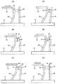
しかしながら、前述の電磁継電器に組み込まれた接点機構では、図7Aに示すように、カード70で可動接触片52の上端縁部を押圧して回動させると、可動接点51が固定接点42に当接する(図7B)。さらに、前記可動接触片52を押し込むと、可動接点51が固定接点42にワイピングするとともに、固定接触片52が後方に撓む(図7C)。このため、可動接点51が固定接点42に当接する位置は、一見、全面接触しているように見えるが、実際は前記可動接点51の下端縁部がピンポイントで接触しているにすぎない。この結果、大容量の電流を流すような電磁継電器に本接点機構を用いた場合、接点摩耗が早くなり、接点寿命が短くなる可能性があった。
一方、図7Dに示すように、前記カード70の押圧力を解除すると、可動接触片52は自己のバネ力で元の位置に復帰しようとするが、可動接点51は固定接点42にワイピングしながら変位するので、引張方向に移動する。このため、接点溶着が生じた場合には大きな引張力を必要とするだけでなく、前記固定接触片43も可動接触片52側に撓むので、より大きな開離力が必要になるという問題点がある。
本発明に係る接点機構は、前記問題点に鑑み、接点寿命が長く、復帰時における接点開離に大きな力を必要としない接点機構を提供することを課題とする。
However, in the contact mechanism incorporated in the electromagnetic relay described above, when the upper edge of the
On the other hand, as shown in FIG. 7D, when the pressing force of the
In view of the above problems, an object of the contact mechanism according to the present invention is to provide a contact mechanism that has a long contact life and does not require a large force for contact release upon return.
本発明に係る接点機構は、前記課題を解決すべく、ベースに、可動接点を備えた可動接触片と固定接点を備えた固定接触片とを立設するとともに、前記可動接点を前記固定接点に接離するように対向させ、水平方向に往復移動する操作部材で前記可動接触片の上端縁部を押圧,解除し、前記可動接触片を回動させて前記可動接点を前記固定接点に接離する接点機構であって、前記可動接触片に湾曲する切り欠き溝を設けて切り出した回動舌片に、前記可動接点を固定した構成としてある。 In order to solve the above-described problems, the contact mechanism according to the present invention has a movable contact piece provided with a movable contact and a fixed contact piece provided with a fixed contact on a base, and the movable contact is used as the fixed contact. The upper and lower edges of the movable contact piece are pressed and released by an operating member that is opposed to come into contact and separated and reciprocates in the horizontal direction, and the movable contact piece is rotated to move the movable contact toward and away from the fixed contact. In this contact mechanism, the movable contact is fixed to a rotary tongue piece cut out by providing a cut-out groove that is curved in the movable contact piece.
本発明によれば、前記可動接触片の動作時および復帰時に前記回動舌片が回動するので、可動接点が固定接点の表面をローリングする。このため、可動接点がピンポイントで片当たりすることがないので、大容量の電流を流しても接点が部分的に摩耗することがなくなり、接点寿命が伸びる。
また、可動接点が固定接点の表面をローリングするので、可動接点と固定接点との間には引張力ではなく、せん断力が作用する。このため、溶着した接点を小さい開離力で強制的に開離でき、信頼性の高い接点機構が得られる。
According to the present invention, when the movable contact piece operates and returns, the rotating tongue piece rotates, so that the movable contact rolls on the surface of the fixed contact. For this reason, since the movable contact does not come into contact with each other at a pinpoint, the contact is not partially worn even when a large-capacity current is passed, and the contact life is extended.
Further, since the movable contact rolls on the surface of the fixed contact, not a tensile force but a shearing force acts between the movable contact and the fixed contact. For this reason, the welded contact can be forcibly opened with a small opening force, and a highly reliable contact mechanism can be obtained.
本発明の実施形態としては、前記切り欠き溝を、前記可動接触片の上端側に向かって開口を有し、かつ、前記可動接点の周囲を囲むように形成してもよい。
本実施形態によれば、操作部材によって、可動接触片の上端縁部が押圧された力が、可動接点に効率良く伝達される。さらに、可動接触片の動作時および復帰時に回動舌片が回動するので、可動接点が固定接点の表面をローリングする。
As an embodiment of the present invention, the notch groove may be formed so as to have an opening toward the upper end side of the movable contact piece and surround the periphery of the movable contact.
According to this embodiment, the force by which the upper end edge part of the movable contact piece was pressed by the operation member is efficiently transmitted to the movable contact. Further, since the rotating tongue piece rotates during operation and return of the movable contact piece, the movable contact rolls on the surface of the fixed contact.
本発明の実施形態としては、前記切り欠き溝はU字形状であってもよく、または、V字形状であってもよい。
本実施形態によれば、用途に応じて種々の切り欠き溝を選択でき、設計の自由が大きい。
As an embodiment of the present invention, the notch groove may be U-shaped or V-shaped.
According to this embodiment, various notch grooves can be selected according to the application, and design freedom is great.
本発明に係る実施形態としては、前記回動舌片のバネ定数を、前記回動舌片の両側に位置する前記可動接触片の縁部のバネ定数より大きくしてもよい。
本実施形態によれば、回動舌片の両側縁部が回動舌片よりも弾性変形しやすくなるので、回動舌片が弾性変形せずに回動し、可動接点が固定接点の表面をより一層ローリングしやすくなる。
As an embodiment according to the present invention, the spring constant of the rotating tongue piece may be larger than the spring constant of the edge portion of the movable contact piece located on both sides of the rotating tongue piece.
According to this embodiment, since both side edges of the rotating tongue are more easily elastically deformed than the rotating tongue, the rotating tongue is rotated without elastic deformation, and the movable contact is the surface of the fixed contact. It becomes easier to roll.
本発明の他の実施形態としては、前記回動舌片の基部の巾寸法を、前記回動舌片の両側に位置する前記可動接触片の縁部の合計巾寸法よりも大きくしてもよい。
本実施形態によれば、前記回動舌片の両側縁部が前記回動舌片よりも弾性変形しやすくなるので、前記回動舌片が弾性変形せずに回動し、可動接点が固定接点の表面をより一層ローリングしやすくなる。
As another embodiment of the present invention, the width of the base of the rotating tongue may be larger than the total width of the edges of the movable contact pieces located on both sides of the rotating tongue. .
According to this embodiment, since both side edges of the rotating tongue are more easily elastically deformed than the rotating tongue, the rotating tongue is rotated without elastic deformation and the movable contact is fixed. It becomes easier to roll the surface of the contact.
本発明の別の実施形態としては、前記可動接触片に、前記切り欠き溝に連通するスリットを下方側に延在してもよい。
本実施形態によれば、前記可動接触片のバネ定数を調整しやすくなり、設計しやすい可動接触片が得られる。
As another embodiment of the present invention, a slit communicating with the cutout groove may extend downward in the movable contact piece.
According to this embodiment, it becomes easy to adjust the spring constant of the said movable contact piece, and the movable contact piece which is easy to design is obtained.
本発明の異なる実施形態としては、前記固定接触片の回動支点が、前記可動接触の回動支点よりも上方に位置するように前記ベースに前記固定接触片を支持してもよい。
本実施形態によれば、固定接触片の剛性が可動接触片よりも大きくなるので、前記固定接触片が前記可動接触片に追従して弾性変形することがなく、可動接点が固定接点の表面をより一層ローリングしやすくなる。
As a different embodiment of the present invention, the fixed contact piece may be supported on the base so that the rotation fulcrum of the fixed contact piece is located above the rotation fulcrum of the movable contact.
According to this embodiment, since the rigidity of the fixed contact piece is larger than that of the movable contact piece, the fixed contact piece does not elastically deform following the movable contact piece, and the movable contact touches the surface of the fixed contact. It becomes easier to roll.
本発明に係る電磁継電器は、前記課題を解決すべく、前述の接点機構を設けた構成としてある。 The electromagnetic relay according to the present invention has a configuration in which the above-described contact mechanism is provided in order to solve the above problems.
本発明によれば、前記可動接触片の動作時および復帰時に前記回動舌片が回動するので、可動接点が固定接点の表面をローリングする。このため、可動接点がピンポイントで片当たりすることがないので、大容量の電流を流しても接点が部分的に摩耗することがなくなり、接点寿命の長い電磁継電が得られる。
また、可動接点が固定接点の表面をローリングするので、可動接点と固定接点との間には引張力ではなく、せん断力が作用する。このため、溶着した接点を小さい開離力で強制的に開離でき、信頼性の高い電磁継電器が得られるという効果がある。
According to the present invention, when the movable contact piece operates and returns, the rotating tongue piece rotates, so that the movable contact rolls on the surface of the fixed contact. For this reason, since the movable contact does not come into contact with each other at a pinpoint, the contact is not partially worn even when a large amount of current is passed, and an electromagnetic relay with a long contact life can be obtained.
Further, since the movable contact rolls on the surface of the fixed contact, not a tensile force but a shearing force acts between the movable contact and the fixed contact. For this reason, there is an effect that the welded contact can be forcibly separated with a small separation force, and a highly reliable electromagnetic relay can be obtained.
本発明に係る接点機構を自己保持型電磁継電器に適用した実施形態を、図1ないし図6の添付図面に従って説明する。なお、以下の説明では、必要に応じて特定の方向や位置を示す用語(例えば、「上」、「下」、「側」、「端」を含む用語)を用いるが、それらの用語の使用は図面を参照した発明の理解を容易にするためであって、それらの用語の意味によって本発明の技術的範囲が限定されるものではない。
また、以下の発明は、本質的に例示にすぎず、本発明、その適用物、あるいは、その用途を制限することを意図するものではない。
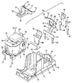
本実施形態に係る電磁継電器は、図2,3に示すように、ベース10と、電磁石ブロック20と、可動鉄片30と、接点機構40と、カード70と、箱形カバー80とから構成されている。
An embodiment in which a contact mechanism according to the present invention is applied to a self-holding electromagnetic relay will be described with reference to the accompanying drawings of FIGS. In the following description, terms indicating specific directions and positions (for example, terms including “up”, “down”, “side”, “end”) are used as necessary. Is for facilitating understanding of the invention with reference to the drawings, and the technical scope of the present invention is not limited by the meaning of these terms.
Further, the following inventions are merely examples in nature, and are not intended to limit the present invention, its application, or its use.
As shown in FIGS. 2 and 3, the electromagnetic relay according to the present embodiment includes a
前記ベース10は、図2に示すように、その上面中央に平面略門型の絶縁壁11を立設して収納部12を形成してあるとともに、前記収納部12の底面にコイル端子孔12a(図3)を設けてある。
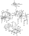
また、前記ベース10は、前記絶縁壁11の外側面に平面略門型の嵌合壁13を隣接するように一体成形して嵌合凹所14を形成してある。前記嵌合凹所14の底面には、一対の係止孔14aを設けてある。
そして、前記ベース10は、前記絶縁壁11の反対側に位置する上面縁部に位置規制リブ15を突設するとともに、前記位置規制リブ15の両側縁部に対向する位置に一対のL字形状位置規制リブ16,17をそれぞれ突設し、後述する固定接点端子41を圧入固定できる構造となっている。また、前記嵌合壁13と前記L字形状位置規制リブ16,17との間に位置する底面には端子孔16a,16aを設けてあり、前記位置規制リブ15と前記L字形状位置規制リブ16,17との間に位置する底面に端子孔17aを設けてある。
As shown in FIG. 2, the
Further, the
The
電磁石ブロック20は、図5に示すように、コイル21を巻回したスプール22に断面T字形状の鉄芯23を挿通し、突出する一端部23aを補助ヨーク24にカシメ固定するとともに、前記一端部23aの先端面と断面略L字形状のヨーク25の水平部とで永久磁石26を挟持する一方、前記鉄芯23の他端部を磁極部23bとしてある。また、前記スプール22には、前記コイル21の引出線をからげて半田付けするコイル端子27が圧入されている。前記補助ヨーク24は前記ヨーク25の側面に当接し、復帰時に前記ヨーク25および永久磁石26とで磁気回路を形成し、外部振動等によって後述する可動鉄片30が誤動作しないようにしている。
As shown in FIG. 5, the electromagnet block 20 includes a
可動鉄片30は、略L字形状に屈曲した磁性材からなり、前記ヨーク25の垂直部の両側縁部に取り付けたヒンジバネ31を介し、前記ヨーク25の下端部25aを支点として回動可能に支持してある。このため、前記可動鉄片30の水平端部30aは前記鉄芯23の磁極部23b接離可能に対向する。また、前記可動鉄片30は、その垂直部の上端縁部に切り欠き部32を設けてある(図2)。
The
接点機構40は、固定接点42をカシメ固定した固定接点端子41と、可動接点51をカシメ固定した可動接点端子50と、復帰時に前記可動接点51に圧接する弾性接触片60とから構成されている。
The
前記固定接点端子41は、固定接点42を設けた固定接触片43の両側縁部に位置決め突起44を突出し加工で形成してある。そして、前記固定接触片43から下方側に延在した一対の端子部45,45を前記ベース10の端子孔17a,17aに挿入するとともに、位置規制リブ15とL字形状位置規制リブ16,17との間に前記固定接触片43を圧入する。これにより、前記位置決め突起44を支点として前記固定接触片43が弾性変形するため、支点間距離の短い剛性の大きい固定接点端子41が得られる。
The fixed contact terminal 41 is formed by projecting
前記可動接点端子50は、図4に示すように、可動接点51を設けた屈曲する可動接触片52から下方側に一対の端子部53,53が延在している。また、前記可動接触片52は、その上端縁部のうち、両側縁部を切り曲げて位置規制舌片54,54を設けてあるとともに、前記位置規制舌片54,54の間に、より一段高くなるように抜け止め舌片55,55を切り曲げてある。そして、前記可動接触片52は、その巾広部に略U字形状もしくは略V字形状のような、前記可動接触片52の上端側に向かって開口を有し、かつ、前記可動接点51の周囲を囲むように形成された切り欠き溝56を設けて回動舌片57を切り出すとともに、前記回動舌片57に可動接点51をカシメ固定してある。さらに、前記可動接触片52は、バネ定数を調整するため、前記切り欠き溝56に連通するスリット58を下方側に設けてある。
特に、前記回動舌片57の基部の巾寸法Xは、前記回動舌片57の両側に位置する前記可動接触片52の縁部の巾寸法Y1,Y2の合計寸法よりも大きい。このため、前記回動舌片57のバネ定数が前記可動接触片52の縁部のバネ定数より大きくなり、前記回動舌片57が弾性変形する前に、前記可動接触片52の両側縁部が弾性変形する。このとき、前記位置規制舌片54,54を有する両側縁部から前記可動接触片52の両側縁部に向かって形成されたC面54a,54aにより、C面54a,54aより下方側に位置する前記可動接触片52の両側縁部が弾性変形しやすくなる。
そして、前記ベース10の端子孔16a,16aに前記端子部53,53を圧入することにより、前記可動接点51が前記固定接点42に接離可能に対向する。
As shown in FIG. 4, the
In particular, the width dimension X of the base portion of the
Then, by pressing the
前記弾性接触片60は、上端縁部から外方側に迫り出すように湾曲した弾性湾曲部61を延在するとともに、下端縁部から側方に係止爪部62,62を延在してある。そして、前記係止爪部62を前記嵌合凹所14の底面に設けた係止孔14a,14aに挿入することにより、前記弾性湾曲部61が前記嵌合壁13から迫り出し、前記可動接点51の背面に圧接する。
The
カード70は、平面略T字形状を有し、その巾狭端部71に沿って一対の弾性腕部72,72を平行に延在し、前記可動鉄片30の切り欠き部32,32に係合可能としてある。また、前記カード70は、その巾広端部73の両側縁部に位置決め突起74,74をそれぞれ突設してある。そして、一対の前記弾性腕部72,72を可動鉄片30の切り欠き部32,32に係合する一方、前記巾広端部73を前記可動接点端子50の位置規制舌片54と抜け止め舌片55との間に係合する。
The
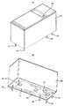
前記箱形カバー80は、前記電磁石ブロック20等を組み込んだベース10に嵌合可能な外形形状を有する。そして、前記ベース10に箱形カバー80を嵌合し、前記ベース10の底面にシール材81(図1B)を注入,固化してシールする一方、前記箱形カバー80のガス抜き孔82(図1A)から内部空気を吸引,除去し、前記ガス抜き孔82を熱封止することにより、組立作業が完了する。
The box-shaped
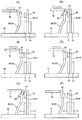
次に、前記電磁継電器の動作を、図5および図6に従って説明する。
コイル21に電圧が印加されていない場合には、可動接触片52のバネ力でカード70を介して可動鉄片30が押圧され、可動接点51が固定接点42から開離しているとともに、弾性接触片60の弾性湾曲部61に圧接している。
Next, the operation of the electromagnetic relay will be described with reference to FIGS.
When no voltage is applied to the
ついで、前記コイル21に電圧を印加して励磁すると、図5Bに示すように、鉄芯23の磁極部23bに可動鉄片30の水平端部30aが吸引され、可動接触片52のバネ力に抗し、可動鉄片30がヨーク25の垂直下端部25aを支点として回動する。このため、前記可動鉄片30の上端部によって押圧されたカード70が水平方向に移動し、可動接触片52の上端縁部を押圧するので、可動接点51が回動して固定接点42に当接する(図6B)。さらに、前記可動接触片52の上端縁部が押し込まれると、前記回動舌片57よりバネ定数が小さい前記可動接触片52の縁部が、前記回動舌片57より先に弾性変形する。このため、可動接点51が固定接点42の表面をローリングしながら変位するとともに(図6C)、可動鉄片30の水平端部30aが前記鉄芯23の磁極部23bに吸着する。この結果、鉄芯23、永久磁石26、ヨーク25および可動鉄片30で磁気回路が閉成されるので、前記コイル21に対する電圧の印加を停止しても、永久磁石26の磁力で前記可動接触片52の動作状態が保持される。
なお、前述したように、切り欠き溝56は前記可動接触片52の上端側に向かって開口を有し、かつ、前記可動接点の周囲を囲むように形成されている。このため、カード70によって、前記可動接触片52の上端縁部が押圧された力は、前記可動接触片52の縁部の弾性変形に左右されることなく、前記回動舌片57を介して可動接点51に効率良く伝達される。
Next, when a voltage is applied to the
As described above, the
そして、前記コイル21に、前記永久磁石26の磁束を打ち消す方向に電圧を印加すると、前記コイル21の磁力および可動接触片52のバネ力によって前記可動鉄片30が前述とは逆方向に回動する。このため、図6Dに示すように、前記カード70が引き戻され、前記可動接触片52の縁部の変形が解除されると共に、前記回動舌片57が前述とは逆方向に回動し、可動接点51が固定接点42の表面をローリングし(図6E)、開離する(図6F)。そして、前記可動接点51が弾性接触片60の弾性湾曲部61に圧接し、前記可動接点51の急激な復帰力を吸収,緩和し、元の状態に復帰する。
このとき、永久磁石26、補助ヨーク24およびヨーク25を介して磁気回路が形成されるので、磁気漏れがない。このため、前記可動鉄片30が外部振動等で回動したとしても、前記可動鉄片30の水平端部30aが鉄芯23の磁極部23bに吸着することがなく、誤動作することがないので、信頼性の高い電磁継電器が得られるという利点がある。
When a voltage is applied to the
At this time, since a magnetic circuit is formed through the
本実施形態によれば、前記可動接点51が固定接点の表面をローリングするように変位する。このため、可動接点51が固定接点42に溶着していたとしても、溶着した可動接点51は固定接点42から、引張力でなく、せん断力で引き離されるので、小さい開離力で溶着した可動接点を固定接点から強制的に開離できる。
また、前記固定接点端子41は、その固定接触片43に設けた位置決め突起44を支点として回動するため、支点間距離が短く、剛性が大きいので、接点開離がより一層容易になるという利点がある。
According to this embodiment, the
Further, since the fixed contact terminal 41 rotates with the
本発明に係る接点機構は、前述の自己保持型電磁継電器に限らず、他の電磁継電器、例えば、自己復帰型電磁継電器に適用してもよいことは勿論である。 The contact mechanism according to the present invention is not limited to the above-described self-holding electromagnetic relay, but may be applied to other electromagnetic relays such as a self-returning electromagnetic relay.
10:ベース
11:絶縁壁
12:収納部
13:嵌合壁
14a:係止孔
15:位置規制リブ
16,17:L字形状位置規制リブ
16a:端子孔
17a:端子孔
20:電磁石ブロック
21:コイル
22:スプール
23:鉄芯
23:磁極部
24:補助ヨーク
25:ヨーク
26:永久磁石
30:可動鉄片
31:ヒンジバネ
40:接点機構
41:固定接点端子
42:固定接点
43:固定接触片
44:位置規制突起
45:端子部
50:可動接点端子
51:可動接点
52:可動接触片
53:端子部
54:位置規制舌片
55:L字形状位置規制舌片
56:切り欠き溝
57:回動舌片
58:スリット
60:弾性接触片
61:弾性湾曲部
62:係止爪部
70:カード(操作部材)
71:巾狭端部
72:巾広端部
80:箱形カバー
81:シール材
82:ガス抜き孔
10: Base 11: Insulating wall 12: Storage part 13: Fitting
71: Narrow end portion 72: Wide end portion 80: Box-shaped cover 81: Sealing material 82: Gas vent hole
Claims (9)
前記可動接触片に湾曲する切り欠き溝を設けて切り出した回動舌片に、前記可動接点を固定したことを特徴とする接点機構。 An operation in which a movable contact piece with a movable contact and a fixed contact piece with a fixed contact are erected on the base, and the movable contact is opposed to and away from the fixed contact, and is reciprocated horizontally. A contact mechanism that presses and releases the upper edge of the movable contact piece with a member, rotates the movable contact piece, and contacts and separates the movable contact with the fixed contact;
A contact mechanism characterized in that the movable contact is fixed to a rotating tongue piece cut out by providing a cut-out groove that is curved in the movable contact piece.
Priority Applications (4)
| Application Number | Priority Date | Filing Date | Title |
|---|---|---|---|
| JP2013166950A JP2015035403A (en) | 2013-08-09 | 2013-08-09 | Contact point mechanism and electromagnetic relay using the same |
| EP14178942.0A EP2835813B1 (en) | 2013-08-09 | 2014-07-29 | Contact mechanism and electromagnetic relay |
| US14/447,047 US20150042425A1 (en) | 2013-08-08 | 2014-07-30 | Contact mechanism and electromagnetic relay |
| CN201410371650.7A CN104347317A (en) | 2013-08-09 | 2014-07-31 | CONTACT MECHANISM AND ELECTROMAGNETIC RELAY using same |
Applications Claiming Priority (1)
| Application Number | Priority Date | Filing Date | Title |
|---|---|---|---|
| JP2013166950A JP2015035403A (en) | 2013-08-09 | 2013-08-09 | Contact point mechanism and electromagnetic relay using the same |
Publications (2)
| Publication Number | Publication Date |
|---|---|
| JP2015035403A true JP2015035403A (en) | 2015-02-19 |
| JP2015035403A5 JP2015035403A5 (en) | 2016-05-26 |
Family
ID=51225424
Family Applications (1)
| Application Number | Title | Priority Date | Filing Date |
|---|---|---|---|
| JP2013166950A Pending JP2015035403A (en) | 2013-08-08 | 2013-08-09 | Contact point mechanism and electromagnetic relay using the same |
Country Status (4)
| Country | Link |
|---|---|
| US (1) | US20150042425A1 (en) |
| EP (1) | EP2835813B1 (en) |
| JP (1) | JP2015035403A (en) |
| CN (1) | CN104347317A (en) |
Cited By (1)
| Publication number | Priority date | Publication date | Assignee | Title |
|---|---|---|---|---|
| WO2018030104A1 (en) * | 2016-08-10 | 2018-02-15 | オムロン株式会社 | Electromagnetic relay |
Families Citing this family (9)
| Publication number | Priority date | Publication date | Assignee | Title |
|---|---|---|---|---|
| JP6263904B2 (en) * | 2013-08-23 | 2018-01-24 | オムロン株式会社 | Electromagnet device and electromagnetic relay using the same |
| JP6341361B2 (en) * | 2013-12-13 | 2018-06-13 | パナソニックIpマネジメント株式会社 | Electromagnetic relay |
| USD772819S1 (en) * | 2014-03-04 | 2016-11-29 | Omron Corporation | Relay |
| JP6422249B2 (en) * | 2014-07-03 | 2018-11-14 | 富士通コンポーネント株式会社 | Electromagnetic relay |
| US9865420B2 (en) * | 2014-07-23 | 2018-01-09 | Fujitsu Component Limited | Electromagnetic relay |
| JP6433706B2 (en) | 2014-07-28 | 2018-12-05 | 富士通コンポーネント株式会社 | Electromagnetic relay and coil terminal |
| USD787450S1 (en) * | 2014-12-04 | 2017-05-23 | Omron Corporation | Electric relay |
| JP6458705B2 (en) * | 2015-10-29 | 2019-01-30 | オムロン株式会社 | relay |
| JP6959728B2 (en) * | 2016-11-04 | 2021-11-05 | 富士通コンポーネント株式会社 | Electromagnetic relay |
Citations (3)
| Publication number | Priority date | Publication date | Assignee | Title |
|---|---|---|---|---|
| JPS62145248U (en) * | 1986-03-07 | 1987-09-12 | ||
| JPS63149046U (en) * | 1987-03-19 | 1988-09-30 | ||
| JP2008034333A (en) * | 2006-02-23 | 2008-02-14 | Denso Corp | Electromagnetic switch |
Family Cites Families (22)
| Publication number | Priority date | Publication date | Assignee | Title |
|---|---|---|---|---|
| AT410856B (en) * | 1994-07-08 | 2003-08-25 | Tyco Electronics Austria Gmbh | RELAY |
| DE19602643A1 (en) * | 1996-01-25 | 1997-07-31 | Siemens Ag | Electromagnetic relay in a narrow design and process for its manufacture |
| JPH1027533A (en) * | 1996-07-11 | 1998-01-27 | Fujitsu Takamizawa Component Kk | Electromagnetic relay |
| JP4085513B2 (en) * | 1999-04-28 | 2008-05-14 | オムロン株式会社 | Electrical equipment sealing structure |
| JP4334158B2 (en) * | 2001-03-26 | 2009-09-30 | 富士通コンポーネント株式会社 | Electromagnetic relay |
| JP4131160B2 (en) * | 2002-11-08 | 2008-08-13 | オムロン株式会社 | Electromagnetic relay |
| JP4131161B2 (en) * | 2002-11-12 | 2008-08-13 | オムロン株式会社 | Electromagnetic relay |
| JP4168733B2 (en) * | 2002-11-12 | 2008-10-22 | オムロン株式会社 | Electromagnetic relay |
| ATE548746T1 (en) * | 2004-01-28 | 2012-03-15 | Tyco Electronics Austria Gmbh | HIGH PERFORMANCE RELAY WITH RESILIENT WORKING CONTACT |
| DE102004060370A1 (en) * | 2004-12-15 | 2006-07-06 | Tyco Electronics Austria Gmbh | Electromagnetic relay |
| JP4742954B2 (en) * | 2006-03-31 | 2011-08-10 | オムロン株式会社 | Electromagnetic relay |
| JP2007273289A (en) * | 2006-03-31 | 2007-10-18 | Omron Corp | Electromagnetic relay |
| CN200993938Y (en) * | 2006-12-29 | 2007-12-19 | 梁雯洁 | Constant magnetic retaining AC contactor |
| JP4952324B2 (en) * | 2007-03-22 | 2012-06-13 | オムロン株式会社 | Electromagnetic relay |
| JP4946559B2 (en) * | 2007-03-22 | 2012-06-06 | オムロン株式会社 | Electromagnetic relay |
| US7710224B2 (en) * | 2007-08-01 | 2010-05-04 | Clodi, L.L.C. | Electromagnetic relay assembly |
| US7659800B2 (en) * | 2007-08-01 | 2010-02-09 | Philipp Gruner | Electromagnetic relay assembly |
| US7705700B2 (en) * | 2007-12-17 | 2010-04-27 | Tyco Electronics Corporation | Relay with overtravel adjustment |
| TW201019364A (en) * | 2008-11-12 | 2010-05-16 | Good Sky Electric Co Ltd | An electromagnetic relay |
| HUE029066T2 (en) * | 2009-02-04 | 2017-02-28 | Hongfa Holdings U S Inc | Electromagnetic relay assembly |
| DE102010063229A1 (en) * | 2010-12-16 | 2012-06-21 | Tyco Electronics Austria Gmbh | Relay with improved contact spring |
| KR101354405B1 (en) * | 2011-06-07 | 2014-01-22 | 후지쯔 콤포넌트 가부시끼가이샤 | Electromagnetic relay and manufacturing method therefor |
-
2013
- 2013-08-09 JP JP2013166950A patent/JP2015035403A/en active Pending
-
2014
- 2014-07-29 EP EP14178942.0A patent/EP2835813B1/en active Active
- 2014-07-30 US US14/447,047 patent/US20150042425A1/en not_active Abandoned
- 2014-07-31 CN CN201410371650.7A patent/CN104347317A/en active Pending
Patent Citations (3)
| Publication number | Priority date | Publication date | Assignee | Title |
|---|---|---|---|---|
| JPS62145248U (en) * | 1986-03-07 | 1987-09-12 | ||
| JPS63149046U (en) * | 1987-03-19 | 1988-09-30 | ||
| JP2008034333A (en) * | 2006-02-23 | 2008-02-14 | Denso Corp | Electromagnetic switch |
Cited By (1)
| Publication number | Priority date | Publication date | Assignee | Title |
|---|---|---|---|---|
| WO2018030104A1 (en) * | 2016-08-10 | 2018-02-15 | オムロン株式会社 | Electromagnetic relay |
Also Published As
| Publication number | Publication date |
|---|---|
| EP2835813A3 (en) | 2015-03-18 |
| EP2835813B1 (en) | 2017-04-05 |
| US20150042425A1 (en) | 2015-02-12 |
| EP2835813A2 (en) | 2015-02-11 |
| CN104347317A (en) | 2015-02-11 |
Similar Documents
| Publication | Publication Date | Title |
|---|---|---|
| JP2015035403A (en) | Contact point mechanism and electromagnetic relay using the same | |
| JP2015035403A5 (en) | ||
| JP4742954B2 (en) | Electromagnetic relay | |
| KR101436268B1 (en) | Electromagnetic relay | |
| EP2650899B1 (en) | Electromagnetic relay | |
| EP2768004B1 (en) | Electromagnetic relay | |
| JP5741338B2 (en) | Terminal member seal structure and electromagnetic relay | |
| KR101175023B1 (en) | Contact switching structure and electromagnetic relay | |
| JP6024287B2 (en) | Electromagnet device, method of assembling the same, and electromagnetic relay using the same | |
| US9437382B2 (en) | Electromagnet device and electromagnetic relay using the same | |
| JP5923932B2 (en) | Contact switching mechanism and electromagnetic relay | |
| WO2015125319A1 (en) | Electromagnetic relay | |
| JP5880233B2 (en) | Electromagnetic relay | |
| JP6065661B2 (en) | Electromagnetic relay | |
| WO2019187780A1 (en) | Relay | |
| JP2007273292A (en) | Electromagnetic relay | |
| JP2014154496A (en) | Electromagnetic relay | |
| JP2014175172A (en) | Electromagnetic relay and method of manufacturing the same | |
| JP2013218890A (en) | Electromagnetic relay | |
| JP6019683B2 (en) | Seal structure of electronic equipment | |
| JP2012160325A (en) | Electromagnetic relay | |
| JP6171286B2 (en) | Electromagnet device | |
| JP2013218882A (en) | Coil terminal | |
| JP2013218886A (en) | Seal structure for electronic apparatus | |
| JP2014175161A (en) | Electromagnetic relay |
Legal Events
| Date | Code | Title | Description |
|---|---|---|---|
| A521 | Request for written amendment filed |
Free format text: JAPANESE INTERMEDIATE CODE: A523 Effective date: 20160405 |
|
| A621 | Written request for application examination |
Free format text: JAPANESE INTERMEDIATE CODE: A621 Effective date: 20160405 |
|
| A977 | Report on retrieval |
Free format text: JAPANESE INTERMEDIATE CODE: A971007 Effective date: 20170125 |
|
| A131 | Notification of reasons for refusal |
Free format text: JAPANESE INTERMEDIATE CODE: A131 Effective date: 20170207 |
|
| A02 | Decision of refusal |
Free format text: JAPANESE INTERMEDIATE CODE: A02 Effective date: 20170801 |