JP2015023456A - Controllable outlet and power consumption management system - Google Patents
Controllable outlet and power consumption management system Download PDFInfo
- Publication number
- JP2015023456A JP2015023456A JP2013150792A JP2013150792A JP2015023456A JP 2015023456 A JP2015023456 A JP 2015023456A JP 2013150792 A JP2013150792 A JP 2013150792A JP 2013150792 A JP2013150792 A JP 2013150792A JP 2015023456 A JP2015023456 A JP 2015023456A
- Authority
- JP
- Japan
- Prior art keywords
- socket
- power
- outlet
- unit
- power supply
- Prior art date
- Legal status (The legal status is an assumption and is not a legal conclusion. Google has not performed a legal analysis and makes no representation as to the accuracy of the status listed.)
- Pending
Links
Images


Abstract
Description
本発明は、制御可能コンセントおよび消費電力管理システムに関する。 The present invention relates to a controllable outlet and a power consumption management system.
コンセントに関しては、操作部からの操作信号に応じた制御信号をコンセントに送信し、各コンセントに設けられた給電制御部を制御することで負荷への給電をオン/オフすることが提案されている。さらに、各コンセントに、個別のアドレスを設定するアドレス設定部をそれぞれ設け、給電制御部は、受信した伝送信号に含まれるアドレスがアドレス設定部により設定された自己のアドレスと一致した場合に、制御信号に基づいて接点部をオン/オフすることも提案されている。(特許文献1)また、家庭内の各電気機器や給湯機器などのエネルギー消費量や運転状況をモニタリングし、自動制御する分野において、電気機器の差込プラグにおけるICタグに格納されている識別情報の読み取りに関する提案もなされている。(特許文献2) Regarding outlets, it has been proposed that a control signal corresponding to an operation signal from the operation unit is transmitted to the outlet, and power supply to the load is turned on / off by controlling a power supply control unit provided in each outlet. . In addition, each outlet has an address setting unit for setting an individual address, and the power supply control unit controls when the address included in the received transmission signal matches its own address set by the address setting unit. It has also been proposed to turn on / off the contact portion based on the signal. (Patent Document 1) Also, in the field of monitoring and automatically controlling the energy consumption and operating status of each electrical device or hot water supply device in the home, identification information stored in the IC tag in the plug of the electrical device Proposals have also been made regarding reading. (Patent Document 2)
しかしながら、より有用なコンセントおよび電力管理システムに関してはさらに検討すべき課題が多い。 However, there are many more issues to consider regarding more useful outlets and power management systems.
本発明の課題は、上記に鑑み、より有用なコンセントおよび電力管理システムを提案することにある。 In view of the above, an object of the present invention is to propose a more useful outlet and power management system.
上記課題を達成するため、本発明は、電力供給部と、前記電力供給部の総電力消費を検知する電力メータと、前記電力供給部に接続される複数の電力消費部に流れる電流をそれぞれ検出する複数の電流センサと、前記電力メータと前記複数の電流センサにより前記複数の電力消費部のそれぞれの電力消費を算定する制御部とを有することを特徴とする電力管理システムを提供する。これによって簡単な構成で各電力消費部の電力消費を個別に算定することが可能となる。 In order to achieve the above object, the present invention detects a current flowing through a power supply unit, a power meter that detects the total power consumption of the power supply unit, and a plurality of power consumption units connected to the power supply unit, respectively. There is provided a power management system comprising: a plurality of current sensors; and a control unit that calculates the power consumption of each of the plurality of power consumption units by the power meter and the plurality of current sensors. This makes it possible to calculate the power consumption of each power consuming unit individually with a simple configuration.
本発明の具体的な特徴によれば、前記複数の電流センサは、前記電力消費部が接続されるコンセントの各ソケットに設けられる。これによってコンセントの管理によりこれに接続される電力消費部の電力消費を算定することができる。 According to a specific feature of the present invention, the plurality of current sensors are provided in each socket of an outlet to which the power consuming unit is connected. Accordingly, the power consumption of the power consumption unit connected to the outlet can be calculated by managing the outlet.
他の具体的な特徴によれば、前記制御部は前記各ソケットへの給電を制御する。これによって、制御部からの管理により不要な電力供給の防止や事故防止ができる。 According to another specific feature, the control unit controls power feeding to the sockets. As a result, unnecessary power supply and accidents can be prevented by management from the control unit.
本発明の他の特徴によれば、電力供給部から給電されるソケットを有し、前記ソケットを通じ前記ソケットに接続される電力消費部に流れる電流を検出する電流センサと、前記電流センサの電流を前記電力供給部に送信する送信部とを有することを特徴とするコンセントが提供される。これによって、電力管理に有用な情報をソケット毎に簡単に取得することができる。 According to another aspect of the present invention, the current sensor includes a socket fed from a power supply unit, and detects a current flowing through a power consumption unit connected to the socket through the socket; and a current of the current sensor There is provided an outlet characterized by having a transmission unit for transmitting to the power supply unit. Thereby, information useful for power management can be easily obtained for each socket.
具体的な特徴によれば、前記送信部は、前記ソケットに接続される電力消費部を特定する特定情報を前記電力供給部に送信する。これによって、コンセントの管理によりこれに接続される電力消費部を管理できる。 According to a specific feature, the transmission unit transmits specific information specifying a power consumption unit connected to the socket to the power supply unit. Thereby, the power consumption unit connected to the outlet can be managed by managing the outlet.
他の具体的な特徴によれば、記送信部は、前記ソケットに電力消費部が接続されているか否かの情報を前記電力供給部に送信する。これによって、電力供給部からの管理により不要な電力供給の防止や事故防止ができる。 According to another specific feature, the transmission unit transmits information about whether or not a power consumption unit is connected to the socket to the power supply unit. Thereby, unnecessary power supply and accidents can be prevented by management from the power supply unit.
他の具体的な特徴によれば、前記電力供給部からの制御に基づき前記ソケットをオンオフするスイッチを有する。これによって、これによって、電力供給部からの管理により不要な電力供給の防止や事故防止ができる。 According to another specific feature, the switch includes a switch for turning on and off the socket based on control from the power supply unit. Thereby, unnecessary power supply and accidents can be prevented by management from the power supply unit.
他の具体的な特徴によれば、前記電力供給部からの制御に基づき前記ソケットに接続される電力消費部に制御信号を伝達する。これによって、電力供給部による電力消費部の統括管理が可能となる。 According to another specific feature, a control signal is transmitted to a power consuming unit connected to the socket based on control from the power supply unit. As a result, the power supply unit can perform integrated management of the power consumption unit.
本発明の他の特徴によれば、電力供給部から給電されるソケットと、前記電力供給部からの制御に基づき前記ソケットをオンオフするスイッチとを有することを特徴とするコンセントが提供される。 According to another aspect of the present invention, there is provided an outlet including a socket supplied with power from a power supply unit and a switch for turning on and off the socket based on control from the power supply unit.
本発明の他の特徴によれば、電力供給部から給電されるソケットと、前記ソケットに接続される電力消費部を特定する特定情報を前記電力供給部に送信する送信部とを有することを特徴とするコンセント。 According to another aspect of the present invention, the power supply unit includes a socket fed from a power supply unit, and a transmission unit that transmits specific information specifying a power consumption unit connected to the socket to the power supply unit. Outlet.
本発明の他の特徴によれば、電力供給部から給電されるソケットと、前記電力供給部からの制御に基づき前記ソケットに接続される電力消費部に制御信号を伝達する伝達部とを有することを特徴とするコンセント。 According to another aspect of the present invention, the power supply unit includes a socket fed from a power supply unit, and a transmission unit that transmits a control signal to a power consumption unit connected to the socket based on control from the power supply unit. Outlet characterized by.
上記のように、本発明によれば、より有用なコンセントおよびコンセントシステムが提供される。 As described above, the present invention provides a more useful outlet and outlet system.
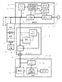
図1は、本発明の実施の形態に係る実施例1の全体構成を示すブロック図である。実施例1は、家庭内におけるコンセントシステムを構成している。商用電源2は家庭内の電源部4に引き込まれ、電力メータ6を経由して分電盤8に接続されている。統括制御部10は、分電盤8を制御するとともにその状態を監視している。統括制御部10はPLC(Power Line Communicaions)モデム12を介して制御信号を電力線通信に合成し送信することより家庭内におけるコンセントシステムを制御している。なお、統括制御部10の記憶部13は、後述のように各コンセントのどのソケットにどの家電が接続されているかの情報を記憶する。統括制御部10の制御は操作部14の設定によって行われ、制御状態は表示部16で表示される。表示部はまた、後述するように、コンセントの各ソケットを介して流れる電流の検知結果と電力メータに基づき、総電力消費とともに家電毎の消費電力をそれぞれ表示する。
FIG. 1 is a block diagram showing an overall configuration of Example 1 according to the embodiment of the present invention. Example 1 constitutes an outlet system in the home. The
分電盤8には、家庭内各所に配置されたコンセント18が接続される。図1では、簡単のためコンセント18の詳細を一つだけ図示し、他は省略しているが、破線で示すように、分電盤8には多数の同様なコンセントが接続される。これらのコンセントは、統括制御部10によって制御可能であるが、コンセント18に基づいてその詳細を説明する。コンセント18は、分電盤8からの電力をスイッチ20経由でソケット22から出力する。コンセント18のPLCモデム24は、電力線通信により統括制御部10から送信される制御信号を分波し、これに基づいてスイッチ20のオンオフを制御する。例えば、長期間の旅行等が予定されている時など、操作部14の操作によりソケット22について待機電流オフモードを設定すれば、統括制御部10から制御信号が送信され、スイッチ20をオフするのでソケット22に接続されている不要な待機電流をオフすることができる。また、操作部14によりタイマーを設定すれば、統括制御部10は一日の所定時間帯のみスイッチ20をオフし他の時間帯はスイッチ20をオンする制御信号を送信する。
The
コンセント18に設けられた電流センサ26は、ソケット22を介して流れる電流を検知し、PLCモデム24を介して電力線通信により検知信号を電源部4に送信する。電源部4ではPLCモデム12が分波する検知信号を統括制御部10が受信する。検知信号は主に三つの目的で利用される。目的の一つ目は、ソケット22を流れる電流の検知信号の変化とこれに対応する電力メータの総電力変化に基づき電力メータ6の総電力変化の原因となっているソケット22を推定することにある。これによって、推定されたソケットを通じて消費される電力を算定する。このようにしてソケット毎の消費電力を把握し、表示部16にこれらをそれぞれ表示することで家電毎の電力消費の「見える化」を実現することができる。また、総電力が所定のピークを越えたときにその要因となる家電(複数も可)を特定して各家電を統括制御することにより、総電力消費を抑える制御をすることができる。
The
検知信号の利用の二つ目の目的は、家電による電流消費がゼロであるソケットへの電力供給をオフすることにある。具体的には、電流センサ26により検出される電流が所定時間以上ゼロである状態が続くと、統括制御部10においてソケット22に家電のプラグが挿入されていないとの判断がなされ、制御信号を送信してスイッチ20をオフにする。なお、スイッチ20をオフした後も、所定時間毎に短時間だけスイッチ20をオンする制御信号が統括制御部10からスイッチ20に送られ、このとき電流センサ26により電流が検知されるか否かがチェックされる。そして電流が検知されるとソケット22に家電のプラグが挿入されたものとの判断がなされ、以後スイッチ20はオンとなる。なお、上記のような家電のプラグの挿入・除去の場合だけでなく、プラグは挿入したままで家電の主電源がオフされて電流消費が完全にゼロとなった場合においても同様にして電流センサの検知信号に基づきスイッチ20がオフされる。主電源がオンされた場合に電流センサの検知信号に基づきこれが判断されてスイッチ20がオンされることも上記と同様である。
The second purpose of using the detection signal is to turn off the power supply to the socket where the current consumption by the home appliance is zero. Specifically, if the current detected by the
検知信号の利用の三つ目の目的は、異常状態にあるソケットへの電力供給をオフすることにある。具体的には、電流センサ26により検出される電流が定格以上の大電流になると家電で異常が起こっているか、またはソケットに異物が挿入されTショートしているものとの判断がなされ、制御信号を送信してスイッチ20をオフにする。この判断を行うリミットの電流値は、ソケットに接続される家電からの情報に基づきソケット毎に設定することができる。また、家電からの情報がない場合に備え、通常の家電使用では考えられない電流値以上であって、かつ危険状態となる電流値との間の値をリミットとして画一的に設定しておく。この画一的なリミットの電流値は個別の家電からの情報に基づいて設定されるリミットの電流値より大きく、また分電盤8のブレーカーが作動する電流値よりも小さい値としておく。これにより、分電盤のブレーカーが作動する前に、各コンセントにおける各ソケット毎にきめ細かく危険防止のために電流供給をオフすることができる。
The third purpose of using the detection signal is to turn off the power supply to the socket in an abnormal state. Specifically, when the current detected by the
家電28は、プラグ30によりコンセント18のソケット22に接続されており、機能部32により家電28本来の機能を達成する。家電28は例えば、テレビ、冷蔵庫、エアコン、照明、掃除機、洗濯機などである。機能部32は、操作部34の手動操作または手動設定に基づき制御部36により制御される。制御部36は、さらに統括制御部10から電力線通信によって送信されPLCモデム38に分波される制御信号に基づき、機能部32を自動制御することができる。制御部36は制御信号に含まれるIPアドレスに基づいて家電28を指定するものか否か識別する。そして、家電28を指定する制御信号であった場合はこれに基づき機能部32を自動制御する。具体的には、例えば家電28がエアコンであったとき、その冷房運転が他のコンセントのソケットに接続される例えば冷蔵庫の冷却運転と重ならないよう機能部32を制御する。このようして、統括制御部10はそれぞれの家電に制御信号を送って電力消費が大きい機能が動作する時間帯を互いにシフトさせ、電力メータ6における総電力が所定のピークを越えないよう統括制御する。
The
制御部36の記憶部40は、家電28を特定するIPアドレスを記憶しており、このIPアドレスを所定の手順でPLCモデム38を介して統括制御部10に送信する。統括制御部10はコンセント18のソケット22に割り振られたIPアドレスを記憶部13に記憶しており、このIPアドレスに基づいて電流センサ26の検知信号の把握およびスイッチ20のオンオフ制御を行っている。さらに、記憶部13には、接続された家電28から受信した各家電のIPアドレスが記憶される。また、IPアドレスを記憶部13は、第2家電50のIPアドレスとソケット44のIPアドレスの対応付けも記憶しており、どのソケット22にどの家電28が接続されているかを特定して、家電毎の消費電力の把握および各家電の制御を行う。家電28を特定するIPアドレスは、例えば、家庭に電力が供給開始されたとき(停電後の電力復活を含む)、またはソケット22にプラグ30が新規に挿入されたとき、またはスイッチ20がオンされたときに統括部10に送信され、統括制御部10の記憶部13に記憶された送信済みのIPアドレスとの照合がおこなわれるとともに、変更があったときはIPアドレス記憶の更新が行われる。
The
なお、後述のようにIPアドレスを記憶していないかこれを統括制御部に送信する機能を持たない家電がコンセント18のソケット22に接続された場合は、ソケット22のIPアドレスにそのような家電を示すIDを操作部14により手動で割当入力する。このIDは使用者が任意に決めてよい。この場合、そのような家電を制御することはできないが、ソケット22のIPアドレスに割当てられたIDを通じて家電を特定して上記と同様にその家電の消費電力を算定することができる。そして算定された値を表示部16に表示することにより、その家電の消費電力を「見える化」することができる。
As will be described later, when a home appliance that does not store an IP address or does not have a function of transmitting the IP address to the overall control unit is connected to the
ここで、図1に示した変換コンセント19について説明する。変換コンセント19は、コンセント18と全く同様の構成(電流センサ、PLCモデムおよびスイッチ)をもつものであるが、分電盤8からの直接配線により家庭内の設備として設けられるものではなく、制御可能に 構成されていない通常コンセント17のソケットに差し込むことによりこれを制御可能なコンセントに変換するものである。つまり、通常コンセント17のソケットに変換コンセント19のプラグを差し込み、次いでPLC通信等に対応している対応家電29のプラグを変換コンセント19のソケットに挿入することにより、コンセント18と家電28で説明したのと全く同様の電源部4と対応家電29との連携および制御が可能となる。
Here, the
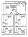
図2は、本発明の実施の形態に係る実施例2の全体構成を示すブロック図である。実施例2も、家庭内におけるコンセントシステムを構成している。図2の実施例2は図1の実施例1と共通する部分が多いので同一部分には同一の番号を付し、必要のない限り説明を省略する。実施例2が実施例1と異なるのは、コンセント42が、第2ソケット44を持つ二口コンセントであること、および家電用の制御コネクタ46、48を持つことである。なお、実施例2における第1家電28は、実施例1における家電28と同じものであり、コンセント42を介した電源部4との連携に関しても実施例1と同様なので、説明は省略する。また、電力線通信により制御が行われる第1家電28が第1ソケット22(図1のソケット22と同じもの)に接続された場合、これに対応する第1制御コネクタ44は使用されない。
FIG. 2 is a block diagram showing an overall configuration of Example 2 according to the embodiment of the present invention. The second embodiment also constitutes an outlet system in the home. Since the second embodiment in FIG. 2 has many parts in common with the first embodiment in FIG. 1, the same parts are denoted by the same reference numerals, and the description thereof is omitted unless necessary. The second embodiment is different from the first embodiment in that the
以下、第2家電50との関係を中心に、実施例2について詳細に説明する。実施例2では、上記のように、コンセント42が、第1ソケット22とこれに対応する第1制御コネクタ46の組、および第2ソケット44とこれに対応する第2制御コネクタ48の組を備えている。なお、図2では、第1ソケット22に第1家電28が、第2ソケット44に第2家電50が接続されているが、これは逆でもよい。このように、コンセント42はいずれのソケットに任意の家電が接続可能されても対応できるよう同様の構成を備えている。そして、第1制御コネクタ46および第2制御コネクタ48は、電力線通信に対応していない家電が第1ソケット22または第2ソケット44に接続された際に家電との通信を行なう。具体的に述べると、コンセント42のPLCモデム52は、統括制御部10から送信される制御信号やIPアドレス要求信号を分波して第1制御コネクタ46および第2制御コネクタ48に出力するとともに、第1制御コネクタ46および第2制御コネクタ48から受信したIPアドレス信号を電力線に合成して統括制御部10に送信する。
Hereinafter, Example 2 is demonstrated in detail focusing on the relationship with the
第2ソケット44に関連して、スイッチ54および電流センサ56が設けられているが、これらは、第1ソケット22に関連して設けられているスイッチ20および電流センサ26と同じものである。なお、PLCモデム52は分波した制御信号に含まれるIPアドレスに基づき制御信号が第1ソケット22を指定したものか第2ソケット44を指定したものか判別して、スイッチ20およびスイッチ54のオンオフ制御を行なう。
A
プラグ58によりコンセント42のソケット44に接続されている第2家電50は、第1家電28と同様にして、機能部60により第2家電50本来の機能を達成する。第2家電50も、例えば、テレビ、冷蔵庫、エアコン、照明、掃除機、洗濯機などであり、電力線通信に対応していないことを除いては第1家電28と性質の異なるものではない。第1家電28と同様にして、第2家電50の機能部60は、操作部64の手動操作または手動設定に基づき制御部62により制御される。制御部62は、制御プラグ66によってコンセント42の第2制御コネクタ48に接続されている。これによって、機能部62は統括制御部10から電力線通信によって送受信されてPLCモデム52で分波・合成される信号により統括制御部10と通信することができる。具体的には、制御部62は制御プラグ66を介して受信する制御信号に含まれるIPアドレスに基づいて第2家電50を指定するものか否か識別し、第2家電50を指定する制御信号であった場合はこれに基づき機能部62を自動制御する。これによって、実施例1の家電28で説明したのと同様にして、他の家電との関係で電力消費が大きい機能が動作する時間帯を互いにシフトさせ、電力メータ6における総電力が所定のピークを越えないようにする統括制御が可能となる。
The
第1家電28と同様にして、第2家電50の制御部62の記憶部68は、第2家電50を特定するIPアドレスを記憶しており、このIPアドレスを所定の手順でコンセント42のPLCモデム52を介して統括制御部10に送信する。統括制御部10は受信した第2家電50のIPアドレスを記憶部13に記憶する。また、IPアドレスを記憶部13は、コンセント42のソケット44に割り振られたIPアドレスを記憶部13に記憶しており、このIPアドレスに基づいて電流センサ56の検知信号の把握およびスイッチ44のオンオフ制御を行う。記憶部13は、第2家電50のIPアドレスとソケット44のIPアドレスの対応付けも記憶しており、どのソケット22にどの家電28が接続されているかを特定して、家電毎の消費電力の把握および各家電の制御を行う。
Similarly to the
図3は、本発明の実施の形態に係る実施例3の全体構成を示すブロック図である。実施例3も、家庭内におけるコンセントシステムを構成している。図3の実施例3は図1の実施例1または図2の実施例2と共通する部分が多いので同一部分にはこれらと同一の番号を付し、必要のない限り説明を省略する。実施例3が実施例1または実施例2と異なるのは、電源部とコンセントとの間の通信が電力線通信ではなく近距離無線通信による点である。 FIG. 3 is a block diagram showing an overall configuration of Example 3 according to the embodiment of the present invention. The third embodiment also constitutes an outlet system in the home. 3 has many parts in common with Example 1 of FIG. 1 or Example 2 of FIG. 2, and therefore, the same parts are denoted by the same reference numerals, and description thereof is omitted unless necessary. The third embodiment is different from the first or second embodiment in that communication between the power supply unit and the outlet is not power line communication but short-range wireless communication.
具体的に説明すると、電源部72の統括制御部10には、近距離無線通信部74が接続されており各コンセントとの間で近距離通信を行う。これに対応してコンセント76には近距離通信部78が設けられおり、電源部の近距離無線通信部74と通信する。コンセント76の近距離通信部78と制御コネクタ48との関係は、図2の実施例2におけるPLCモデム52と第2制御コネクタ48との関係と同じであり、それらの機能も同様である。コンセント76のその他の構成は、図2の第2実施例におけるスイッチ54および電流センサ56と同じなので、同じ番号を付して説明を省略する。プラグ58によりコンセント76のソケット44に接続されるとともに制御プラグ66によってコンセント76の制御コネクタ48に接続されている第2家電50の構成も図2の実施例2と同様なので同じ番号を付して説明を省略する。
More specifically, a short-range
図3の第3実施例における変換コンセント80および第3家電82は、それぞれ基本的にはコンセント76および第2家電50と同じ構成である。従って、同一部分にはこれらと同一の番号を付して説明を省略する。なお、コンセント76のスイッチ54と変換コンセント80のスイッチ54およびこれらに付属するそれぞれの電流センサの識別はIPアドレスによるもので、図2の実施例2におけるスイッチ20とステップS54等の間の識別と同様である。
The
変換コンセント80がコンセント76と異なるのは、図1の第1実施例で説明した変換コンセント19と同様にして、分電盤8からの直接配線により家庭内の設備として設けられるものではなく、通常コンセント84のソケット86に変換コンセントのプラグ88を差し込む構成である点である。これによって、通常コンセント84が制御可能なコンセントに変換され、第2家電50と同様にして、第3家電の電力消費が把握できるとともにその制御を行うことができる。
The
図4は、実施例1から実施例3における統括制御部10の動作を説明する基本フローチャートである。フローは、電源部4または72に商用電源2からの給電が開始されるとスタートし、ステップS2で各ソケットとの通信を確立する手順を実行する。次いで、ステップS4で各ソケットのIPアドレスを確認する処理を行うとともに、ステップS6で各家電のIPアドレスを確認する処理を行いステップS8に移行する。なお、ステップS6は、IPアドレスを持たない家電についてソケットのIPアドレスに家電のIDを手動で割当入力する処理も含む。
FIG. 4 is a basic flowchart for explaining the operation of the
ステップS8では、プラグが挿入されていないと判断されるソケットをオフにする。次いでステップS10では待機電流オフモードが設定されているか否かチェックし、該当しなければステップS12で設定対象ソケットをオンにしてS14に移行する。なお対象ソケットが元々オンであればステップS12では何もせずステップS14に移行する。一方、ステップS10で待機電流オフモードの設定が確認されるとステップS16に進み、設定対象ソケットをオフにしてステップS14に移行する。 In step S8, the socket determined to have no plug inserted is turned off. Next, in step S10, it is checked whether or not the standby current off mode is set. If not, the setting target socket is turned on in step S12 and the process proceeds to S14. If the target socket is originally on, nothing is performed in step S12, and the process proceeds to step S14. On the other hand, if the setting of the standby current off mode is confirmed in step S10, the process proceeds to step S16, the setting target socket is turned off, and the process proceeds to step S14.
ステップS14では、プラグが挿入されていなかったソケットに新たに家電のプラグが挿入されたか否かチェックする。プラグの新規挿入が確認されると該当ソケットをオンにし、ステップS20でその家電についてIPアドレスを確認する処理をしてステップS22に移行する。一方、ステップS14で新規家電プラグの挿入が確認されない場合は直接ステップS22に移行する。 In step S14, it is checked whether or not a new home appliance plug has been inserted into the socket in which no plug has been inserted. When new insertion of the plug is confirmed, the corresponding socket is turned on, and processing for confirming the IP address of the home appliance is performed in step S20, and the process proceeds to step S22. On the other hand, if insertion of a new home appliance plug is not confirmed in step S14, the process directly proceeds to step S22.
ステップS22では、プラグが挿入されていてオフ状態にあったソケットがオンになったか否かチェックする。ソケットのオンが確認されるとステップS24でその家電についてIPアドレスを確認する処理をしてステップS26に移行する。一方、ステップS22でソケットのオンが確認されない場合は直接ステップS26に移行する。ステップS22では、さらに複数のコンセントおよびソケットをまとめているブレーカーがオンになったか否かもチェックしており、ブレーカーのオンが確認されると、各ソケットのオンの場合と同様、とステップS24で該当するブレーカーの支配下にある各家電についてIPアドレスを確認する処理をしてステップS26に移行する。 In step S22, it is checked whether the socket in which the plug is inserted and in the off state is turned on. When it is confirmed that the socket is turned on, in step S24, a process for confirming the IP address of the home appliance is performed, and the process proceeds to step S26. On the other hand, if it is not confirmed in step S22 that the socket is turned on, the process directly proceeds to step S26. In step S22, it is also checked whether or not a breaker that collects a plurality of outlets and sockets has been turned on. If the breaker is turned on, as in the case of each socket being turned on, the same applies in step S24. The process of confirming the IP address of each home appliance under the control of the breaker to be performed is performed, and the process proceeds to step S26.
ステップS26では、電流センサに検知信号に基づき、電流が所定時間以上ゼロであってプラグが除去されたと判断できるか、または、電流が定格以上の大電流になりソケットのショートなどの異常状態であると判断できるか否かチェックする。そして所定時間以上電流ゼロである状態または定格以上の電流が検知されるとステップS28に進み、該当ソケットをオフする。次いで、ステップS30でソケットに挿入されていた家電のIPアドレスの記憶をキャンセルしてステップS32に移行する。一方、ステップS26で所定時間以上電流ゼロである状態または定格以上の電流のいずれもが検知されない場合は、直接ステップS32に移行する。 In step S26, based on the detection signal from the current sensor, it can be determined that the current is zero for a predetermined time or more and the plug has been removed, or the current is a large current exceeding the rating, and the socket is in an abnormal state such as a short circuit. Check if it can be determined. When a current zero state or a current exceeding the rated value is detected for a predetermined time or longer, the process proceeds to step S28, and the corresponding socket is turned off. Next, the storage of the IP address of the home appliance inserted in the socket in step S30 is canceled, and the process proceeds to step S32. On the other hand, if neither the state where the current is zero for the predetermined time or the current exceeding the rated value is detected in step S26, the process proceeds directly to step S32.
ステップS32では、電流センサや電力メータ等に基づく各ソケットのモニタおよび制御のための処理を行ってステップS34に移行する。ステップS34では、商用電源2から電源部4または72への給電が行われているか否かチェックし、給電中であればステップS10に戻って、以下給電中である限り、ステップS10からステップS34を繰り返し、種々の状況変化に対応する。
In step S32, processing for monitoring and controlling each socket based on a current sensor, a power meter, and the like is performed, and the process proceeds to step S34. In step S34, it is checked whether or not power is being supplied from the
図5は、図4のステップS6、ステップS20およびステップS24における家電IPアドレス確認処理の詳細を示すフローチャートである。フローがスタートするとステップS40で対象のソケットを一つ特定する。そしてステップS42で家電IPアドレスの確認が所定回数以上行われたか否かチェックし、所定回数以下であればステップS44に進んでそのソケットに接続されている家電にIPアドレスを要求する。次いでステップS46で家電からIPアドレスの返信があったか否かチェックし、返信がなければIPアドレスを持たない家電であると判断してステップS48に移行する。ステップS48では、ソケットに割り当てる家電のIDの手動入力を促す表示を表示部16で行い、ステップS50でこれに従ったソケット割当家電のIDが手動入力されたか否かチェックする。そして手動入力があればステップS52に移行する。一方、ステップS46で家電からのIPアドレス返信が確認できたときは直接ステップS52に移行する。
FIG. 5 is a flowchart showing details of the home appliance IP address confirmation processing in steps S6, S20, and S24 of FIG. When the flow starts, one target socket is specified in step S40. In step S42, it is checked whether or not the home appliance IP address has been confirmed a predetermined number of times or more. If it is less than the predetermined number of times, the process proceeds to step S44 to request an IP address from the home appliance connected to the socket. Next, in step S46, it is checked whether an IP address is returned from the home appliance. If there is no reply, it is determined that the home appliance does not have an IP address, and the process proceeds to step S48. In step S48, a display for prompting manual input of the home appliance ID assigned to the socket is performed on the
ステップS52では、記憶部13に既に記憶されている家電IPアドレスの有無をチェックする。そして記憶IPアドレスがあればステップS54に進み、記憶されているIPアドレスと新たに返信されたIPアドレスを比較し、同一か否かチェックする。同一でなければ、ステップS46で家電IPアドレス更新を確認する表示をステップS16で行い、ステップS58で所定時間内に同意操作があったか否かチェックする。そして同意操作があればステップS60に移行する。一方、ステップS52で記憶家電IPアドレスが確認できないときは直接ステップS60に移行する。また、ステップS54で記憶されているIPアドレスと新たに返信されたIPアドレスが同一であることが確認されたときも直接ステップS60に移行する。これに対し、ステップS58で所定時間内の同意操作確認できない場合はステップS42に戻り、があったか否かチェックする。家電IPアドレスの確認が所定回数以下である限りステップS42からステップS58を繰り返す。
In step S52, the presence / absence of a home appliance IP address already stored in the
ステップS60に至ったときは、新規家電IPアドレスの記憶を行ってステップS64に移行する。ステップS60における「新規家電IPアドレスの記憶」とは、以前に記憶したのと同じIPアドレスを記憶する場合で結果的に記憶が変わらない場合も含む。一方、ステップS42で家電IPアドレスの確認が所定回数以上となった場合は、ステップS62に移行し、該当のソケットについて割当てられる家電が不明である旨の表示を表示部16で行ってステップS64に移行する。ステップS64では、次に確認を行う対象ソケットがあるか否かをチェックし、あればステップS40に戻って、次の対象ソケットについて同じ動作を繰り返す。これに対し、ステップS64で次の対象ソケットがなければ、フローを終了し、図4のステップS8またはステップS22またはステップS26に移行する。
When step S60 is reached, the new home appliance IP address is stored and the process proceeds to step S64. “Storage of new home appliance IP address” in step S60 includes the case where the same IP address as previously stored is stored and the storage does not change as a result. On the other hand, if the home appliance IP address has been confirmed a predetermined number of times or more in step S42, the process proceeds to step S62, and the
図6は、図4のステップS32におけるモニタ・制御処理の詳細を示すフローチャートである。フローがスタートするとステップS472で測定タイミングか否かのチェックが行われ、測定タイミングであればステップS74でソケット毎の電流をモニタするとともにステップS75で電力メータ6によって対応する時刻の総電力をモニタする。そしてステップS76で、総電力および各ソケットの電流によりソケットに接続されている家電毎の電力消費を算定して結果を記憶部13に記憶するとともに表示部16に表示し、ステップS78に移行する。これによって家電毎ごとの消費電力の「見える化」が実現する。一方、ステップS72で測定タイミングでなければ、直接ステップS78に移行する。
FIG. 6 is a flowchart showing details of the monitor / control process in step S32 of FIG. When the flow starts, it is checked in step S472 whether or not it is a measurement timing. If it is the measurement timing, the current for each socket is monitored in step S74 and the total power at the corresponding time is monitored by the
ステップS78では、ソケット毎の消費電力および総電力の推移より処理を必要とするデータが発生しているか否かチェックする。このチェックは、総電力消費が大きくなっている時間帯、頻度、傾向等のチェックに該当する。そして該当するデータがあればステップS80に進み、総電力消費が所定以上となる時間帯を抽出する処理を行う。次いでステップS82では、電流センサの情報に基づき総電力消費を大きくしている要因となっているソケットの組み合せおよび時間帯を分析する処理を行う。さらに、ステップS84では、要因ソケットを抽出する処理を行ってステップS86に移行する。なお、ステップS80、S82およびS84の処理はそれぞれ完了まで行うのではなく、所定の割当時間が過ぎると一旦処理を中断して次のステップに移行する。 In step S78, it is checked whether or not data requiring processing is generated based on changes in power consumption and total power for each socket. This check corresponds to the check of the time zone, frequency, trend, etc. where the total power consumption is large. If there is such data, the process proceeds to step S80, and a process of extracting a time zone in which the total power consumption is equal to or greater than a predetermined value is performed. Next, in step S82, a process of analyzing a combination of sockets and a time zone, which is a factor increasing the total power consumption based on the information of the current sensor, is performed. In step S84, a factor socket is extracted, and the process proceeds to step S86. Note that the processes in steps S80, S82, and S84 are not performed until completion, but once the predetermined allocation time has elapsed, the process is temporarily interrupted and the process proceeds to the next step.
ステップS86ではステップS80、S82およびS84の処理がすべて完了したか否かチェックし、完了していなければステップS88に移行する。ステップS88では、ステップS80、S82およびS84に今回割当てられた処理時間が終了したか否かチェックし、終了であればステップS90に進んで、処理の中断手続を行ってステップS92に移行する。一方、ステップS88で、ステップS80、S82およびS84に今回割当てられた処理時間が終了していなければステップS80に戻り、以下割当時間が終了するまで時分割でステップS80、S82およびS84の処理を繰り返す。また、ステップS86で、ステップS80、S82およびS84の処理がすべて完了したことが検知されると直接ステップS92に移行する。なお、ステップS90で処理の中断手続が行われたときは、図4で次回ステップS32に至ったとき処理を再開する。なお、ステップS78で要処理データがなければ直接ステップS92に移行する。 In step S86, it is checked whether or not the processes in steps S80, S82, and S84 are all completed. If not, the process proceeds to step S88. In step S88, it is checked whether or not the processing time allocated this time to steps S80, S82, and S84 has ended. If it has ended, the process proceeds to step S90, the process is interrupted, and the process proceeds to step S92. On the other hand, if the processing time currently assigned to steps S80, S82, and S84 has not ended in step S88, the process returns to step S80, and the processes of steps S80, S82, and S84 are repeated in a time-sharing manner until the allocation time ends. . If it is detected in step S86 that all the processes in steps S80, S82, and S84 are completed, the process directly proceeds to step S92. When the process interruption procedure is performed in step S90, the process is resumed when step S32 is reached next time in FIG. If there is no data to be processed in step S78, the process directly proceeds to step S92.
ステップS92では、ステップS80、S82およびS84の処理結果に基づいて決められる要管理時間帯(総電力消費が大きくなることが想定される時間帯)になったか否かチェックする。該当しなければ、ステップS94に進み、総電力消費が所定以上となったか否かチェックする。該当すればステップS96に進み、要因ソケットを抽出してステップS98に移行する。一方、ステップS92で要管理時間帯となったときは以前からの分析に基づく要因ソケットのデータを採用してステップS98に進む。このように、予め分析に従って予想される要管理時間帯でなくても、臨時的に総電力消費が所定上となればステップS96によって要因ソケットを抽出し対応が行われる。 In step S92, it is checked whether or not a management required time zone (a time zone in which total power consumption is expected to increase) determined based on the processing results of steps S80, S82, and S84 has been reached. If not, the process proceeds to step S94, and it is checked whether or not the total power consumption is equal to or greater than a predetermined value. If applicable, the process proceeds to step S96, the factor socket is extracted, and the process proceeds to step S98. On the other hand, when the management time zone is required in step S92, the factor socket data based on the previous analysis is adopted and the process proceeds to step S98. In this way, even if it is not the management time zone that is predicted in advance according to the analysis, if the total power consumption temporarily rises to a predetermined value, the factor socket is extracted in step S96 and the response is performed.
ステップS98要因ソケットに接続されている家電を統括管理し消費電力のピークをずらすよう指示する管理信号を各家電に出力しフローを終了する。一方、ステップS94で総電力消費が所定以上でなければ直ちにフローを終了する。 In step S98, the home appliance connected to the factor socket is integratedly managed and a management signal instructing to shift the peak of power consumption is output to each home appliance, and the flow is terminated. On the other hand, if the total power consumption is not greater than or equal to the predetermined value in step S94, the flow is immediately terminated.
本発明は、コンセントおよび電力管理システムに適用することができる。 The present invention can be applied to an outlet and a power management system.
4、72 電力供給部
6 電力メータ
26、56、 電流センサ
10 制御部
18、19、42、76、80 コンセント
20、54 スイッチ
4, 72
Claims (11)
Priority Applications (3)
| Application Number | Priority Date | Filing Date | Title |
|---|---|---|---|
| JP2013150792A JP2015023456A (en) | 2013-07-19 | 2013-07-19 | Controllable outlet and power consumption management system |
| US14/905,389 US10063094B2 (en) | 2013-07-19 | 2014-07-11 | Power management system and power outlet unit |
| PCT/JP2014/068573 WO2015008706A1 (en) | 2013-07-19 | 2014-07-11 | Power management system and connection relay unit |
Applications Claiming Priority (1)
| Application Number | Priority Date | Filing Date | Title |
|---|---|---|---|
| JP2013150792A JP2015023456A (en) | 2013-07-19 | 2013-07-19 | Controllable outlet and power consumption management system |
Publications (2)
| Publication Number | Publication Date |
|---|---|
| JP2015023456A true JP2015023456A (en) | 2015-02-02 |
| JP2015023456A5 JP2015023456A5 (en) | 2016-07-21 |
Family
ID=52487554
Family Applications (1)
| Application Number | Title | Priority Date | Filing Date |
|---|---|---|---|
| JP2013150792A Pending JP2015023456A (en) | 2013-07-19 | 2013-07-19 | Controllable outlet and power consumption management system |
Country Status (1)
| Country | Link |
|---|---|
| JP (1) | JP2015023456A (en) |
Cited By (3)
| Publication number | Priority date | Publication date | Assignee | Title |
|---|---|---|---|---|
| JP5979297B1 (en) * | 2015-09-25 | 2016-08-24 | 日本電気株式会社 | Control device, control method and program, and information device |
| CN106443102A (en) * | 2016-10-31 | 2017-02-22 | 宁波三星医疗电气股份有限公司 | Power supply distribution system for twin-core electric energy meter |
| CN106597088A (en) * | 2016-10-31 | 2017-04-26 | 宁波三星医疗电气股份有限公司 | Power source distribution system of dual-core electric energy meter |
Citations (2)
| Publication number | Priority date | Publication date | Assignee | Title |
|---|---|---|---|---|
| WO2012111373A1 (en) * | 2011-02-14 | 2012-08-23 | NEBU Kazuaki | Energy consumption monitoring system, method, and computer program |
| JP2013243555A (en) * | 2012-05-21 | 2013-12-05 | Ntt Docomo Inc | Information processing device, power tap, server device, information processing system, information processing method, and program |
-
2013
- 2013-07-19 JP JP2013150792A patent/JP2015023456A/en active Pending
Patent Citations (2)
| Publication number | Priority date | Publication date | Assignee | Title |
|---|---|---|---|---|
| WO2012111373A1 (en) * | 2011-02-14 | 2012-08-23 | NEBU Kazuaki | Energy consumption monitoring system, method, and computer program |
| JP2013243555A (en) * | 2012-05-21 | 2013-12-05 | Ntt Docomo Inc | Information processing device, power tap, server device, information processing system, information processing method, and program |
Non-Patent Citations (7)
| Title |
|---|
| 加藤 丈和 TAKEKAZU KATO: "i−Energy Profile:スマートタップネットワークによるエネルギーの情報化プロファイル i-", 電子情報通信学会論文誌, vol. 第J94-B巻 第10号, JPN6017043234, 1 October 2011 (2011-10-01), JP, pages 1232 - 1245 * |
| 塚本 昌彦 MASAHIKO TSUKAMOTO 他: "エネルギーの情報化 〜ITによる電力マネジメント〜 i-Energy: Electric Power Management by Informati", 情報処理, vol. 第51巻 第8号, JPN6014034129, 15 August 2010 (2010-08-15), JP, pages 934 - 942 * |
| 明山 寛史 HIROSHI AKEYAMA 他: "ネットワークから制御可能な多機能コンセント Multifunctional Outlet with Web Functions", FIT2008 第7回情報科学技術フォーラム 講演論文集 FORUM ON INFORMATION TECHNOLOGY 2008, vol. 第1分冊, JPN6014034133, 20 August 2008 (2008-08-20), pages 259 - 262 * |
| 森本 尚之 他: "電力のインテリジェント制御機能つきスマートタップの開発", 平成23年度 情報処理学会関西支部 支部大会 講演論文集, vol. 第2011巻, JPN6014034135, 22 September 2011 (2011-09-22), pages F-101 * |
| 浅野 浩志 他, スマートグリッド教科書 SMARTGRID TEXTBOOK, vol. 初版, JPN6014034126, 1 March 2011 (2011-03-01), pages 184 - 205 * |
| 浅野 浩志 他, スマートグリッド教科書 SMARTGRID TEXTBOOK, vol. 初版, JPN6014034126, 1 March 2011 (2011-03-01), pages 188 - 205 * |
| 福井類 RUI FUKUI: "既存家電の消費電流監視および電源制御を可能にする知能化電源タップ An Intelligent-Outlet-Tap for C", 第27回日本ロボット学会学術講演会予稿集DVD−ROM 2009年 THE 27TH ANNUAL , JPN6017043236, 15 September 2009 (2009-09-15), pages RSJ2009AC3G2-01 * |
Cited By (5)
| Publication number | Priority date | Publication date | Assignee | Title |
|---|---|---|---|---|
| JP5979297B1 (en) * | 2015-09-25 | 2016-08-24 | 日本電気株式会社 | Control device, control method and program, and information device |
| CN106443102A (en) * | 2016-10-31 | 2017-02-22 | 宁波三星医疗电气股份有限公司 | Power supply distribution system for twin-core electric energy meter |
| CN106597088A (en) * | 2016-10-31 | 2017-04-26 | 宁波三星医疗电气股份有限公司 | Power source distribution system of dual-core electric energy meter |
| CN106443102B (en) * | 2016-10-31 | 2019-03-26 | 宁波三星医疗电气股份有限公司 | A kind of power distribution system for twin-core electric energy meter |
| CN106597088B (en) * | 2016-10-31 | 2019-05-17 | 宁波三星医疗电气股份有限公司 | A kind of power distribution system of twin-core electric energy meter |
Similar Documents
| Publication | Publication Date | Title |
|---|---|---|
| US9685822B2 (en) | Management apparatus and management method for electrical appliances | |
| EP3125374B1 (en) | Operation control device for electronic apparatus | |
| WO2015008706A1 (en) | Power management system and connection relay unit | |
| CN102870307B (en) | Electric current supplying module | |
| EP3183706B1 (en) | System and method of controlling supply of electrical power | |
| JP2010114967A (en) | Transmitter, management method, and management system for electric use | |
| JP2010213411A (en) | Power management system | |
| WO2014208773A1 (en) | Device registration apparatus and device registration method | |
| KR101183388B1 (en) | Power monitoring system and plug module | |
| KR101167585B1 (en) | In-house network control system and method for smart home | |
| JP2015023456A (en) | Controllable outlet and power consumption management system | |
| EP1898292B1 (en) | Apparatus and method for a global management of electrical power in an electric network | |
| JP2017017776A (en) | Power management device, power management system, power management method and program | |
| JP2015119329A (en) | Power management system, power supply part and connection relay part | |
| JP2013042589A (en) | Power management device and power management system | |
| KR20160041027A (en) | Apparatus for controlling operation of electronic device | |
| JP2019016823A (en) | Repeating installation | |
| KR20150005345A (en) | Power managing apparatus and power managing system using the same | |
| KR101892757B1 (en) | A home appliance and a control method the same | |
| KR20180092703A (en) | Power supply control apparatus and method thereof | |
| JP2016029768A (en) | Radio communication device | |
| JP6273565B2 (en) | Measuring device | |
| KR20170063502A (en) | Apparatus for controlling operation of electronic device | |
| KR20170064530A (en) | Apparatus for controlling operation of electronic device | |
| NZ730125A (en) | System and method of controlling supply of electrical power |
Legal Events
| Date | Code | Title | Description |
|---|---|---|---|
| A521 | Request for written amendment filed |
Free format text: JAPANESE INTERMEDIATE CODE: A523 Effective date: 20160603 |
|
| A621 | Written request for application examination |
Free format text: JAPANESE INTERMEDIATE CODE: A621 Effective date: 20160606 |
|
| A131 | Notification of reasons for refusal |
Free format text: JAPANESE INTERMEDIATE CODE: A131 Effective date: 20170829 |
|
| A521 | Request for written amendment filed |
Free format text: JAPANESE INTERMEDIATE CODE: A523 Effective date: 20171025 |
|
| A131 | Notification of reasons for refusal |
Free format text: JAPANESE INTERMEDIATE CODE: A131 Effective date: 20171114 |
|
| A521 | Request for written amendment filed |
Free format text: JAPANESE INTERMEDIATE CODE: A523 Effective date: 20171222 |
|
| A02 | Decision of refusal |
Free format text: JAPANESE INTERMEDIATE CODE: A02 Effective date: 20180130 |