JP2015020249A - Diesel power tool motor with built-in striking mechanism - Google Patents
Diesel power tool motor with built-in striking mechanism Download PDFInfo
- Publication number
- JP2015020249A JP2015020249A JP2013151246A JP2013151246A JP2015020249A JP 2015020249 A JP2015020249 A JP 2015020249A JP 2013151246 A JP2013151246 A JP 2013151246A JP 2013151246 A JP2013151246 A JP 2013151246A JP 2015020249 A JP2015020249 A JP 2015020249A
- Authority
- JP
- Japan
- Prior art keywords
- rotor
- pneumatic tool
- built
- tool motor
- rear end
- Prior art date
- Legal status (The legal status is an assumption and is not a legal conclusion. Google has not performed a legal analysis and makes no representation as to the accuracy of the status listed.)
- Granted
Links
- 230000007246 mechanism Effects 0.000 title claims abstract description 41
- 230000009471 action Effects 0.000 claims abstract description 12
- 230000002093 peripheral effect Effects 0.000 claims description 3
- 230000001360 synchronised effect Effects 0.000 claims 1
- 230000000694 effects Effects 0.000 description 4
- 238000004519 manufacturing process Methods 0.000 description 4
- 230000008901 benefit Effects 0.000 description 3
- 238000004806 packaging method and process Methods 0.000 description 3
- 230000006835 compression Effects 0.000 description 2
- 238000007906 compression Methods 0.000 description 2
- 238000012986 modification Methods 0.000 description 2
- 230000004048 modification Effects 0.000 description 2
- 230000004308 accommodation Effects 0.000 description 1
- 238000011156 evaluation Methods 0.000 description 1
- 210000003746 feather Anatomy 0.000 description 1
- 238000009434 installation Methods 0.000 description 1
- 230000009467 reduction Effects 0.000 description 1
- 238000004904 shortening Methods 0.000 description 1
Images


Landscapes
- Percussive Tools And Related Accessories (AREA)
Abstract
Description
本発明は、気動工具の局所構造に関わり、特に打撃機構内蔵のオリジナルな気動工具モータ構造に関する。 The present invention relates to a local structure of a pneumatic tool, and more particularly to an original pneumatic tool motor structure with a built-in striking mechanism.
気動工具製品は気動スパナと言えば、主に大型ナットや、ネジの締付けまたは緩めに使用されるもので、大型ネジ、ナットに必要な締付けトルク、緩めトルクが非常に大きいから、それに応じてそれら自身の生じるトルクも高く求められる。該気動スパナは動作の時、通常は、打撃機構を設け、それによりトルクを生じることになっており、そこで、該打撃機構の構成と作動原理では通常、ハンマー台の中に、二ブロック状ハンマーが位置決められるように収容され、該ハンマーは、駆動軸の順方向または逆方向の回転に伴い、決まった所で、惰性で持続的にスイングし続けることで、ハンマーが生じたトルクで、作用力が高まる。 Pneumatic tool products are mainly used for tightening or loosening large nuts and screws, and the tightening torque and loosening torque required for large screws and nuts are very large. Therefore, the torque generated by them is also highly required. The pneumatic spanner is usually provided with a striking mechanism during operation, thereby generating torque, and the structure and operating principle of the striking mechanism is usually in a two-block form in a hammer base. The hammer is housed so that it can be positioned, and the hammer operates at the torque generated by the hammer by continuously swinging with inertia at a fixed place as the drive shaft rotates in the forward or reverse direction. Power increases.
しかし、上述した該打撃機構の従来の構造形態では実際に応用した経験から、次のような幾つかの問題点があると分かった。 However, from the experience of actual application in the conventional structure of the hitting mechanism described above, it has been found that there are several problems as follows.
該打撃機構は従来の設置形態において、通常、気動工具の気動モータの先端側に、その縦方向の長さに相当する先端側のリバースケースを増設し、該先端側のリバースケースに、該打撃機構のハンマー台とブロック状ハンマー、支持軸などの部品を組み立て、収容するように設けられているが、該打撃機構が気動モータの先端側に突き出た形態となり、気動工具本体の縦方向の長さや体積が大幅に増加、気動工具の出力軸の末端と取っ手との間に突き出た部分もかなり長くなり、使用者にとって非常に重くて、余計に力が掛かり、使いにくいという欠点があること、それに、製造元にとって、従来の打撃機構が気動モータの先端側に突き出た形となり、同じく縦方向の長さの体積が大幅に増加しているから、材料、製造、組立や包装などのコストも大幅に増加しているという問題点があり、好適な産業上の経済的効果にも一致しない。 In the conventional installation form, the striking mechanism is normally equipped with a reverse case on the tip side corresponding to the length in the vertical direction on the tip side of the pneumatic motor of the pneumatic tool, It is provided to assemble and accommodate parts such as the hammer base, block hammer, support shaft, etc. of the striking mechanism, but the striking mechanism is projected to the tip side of the pneumatic motor, The length and volume in the vertical direction are significantly increased, and the protruding part between the end of the output shaft of the pneumatic tool and the handle is considerably long, making it very heavy for the user, applying extra force, and being difficult to use There is a drawback, and for the manufacturer, the conventional striking mechanism protrudes to the tip side of the pneumatic motor, and the volume of the length in the vertical direction is also greatly increased. Packaging etc. There is a problem in that the door has also increased significantly, does not match the economic effect on a suitable industry.
それゆえ、上述した従来の打撃機構を有する気動工具構造に存在している問題点について、より理想的でかつ実用性のあるオリジナルな構造を開発するのが、関連業界がそれに取り組んで目指している目標と方向でもある。 Therefore, the related industry aims to develop a more ideal and practical original structure for the problems existing in the pneumatic tool structure having the conventional hitting mechanism described above. It is also a goal and direction.
それに鑑みて、発明者は、関連製品の製造、開発と設計に携わる長年の経験を持っており、上述した目標について、詳しく設計、慎重に評価したうえ、ようやく、実用性のある本発明を得られたわけである。 In view of this, the inventor has many years of experience in the manufacture, development and design of related products, and after the detailed design and careful evaluation of the above-mentioned goals, finally, the present invention with practicality was obtained. That is why.
本発明は、打撃機構内蔵の気動工具モータを提供することを目的とし、解決しようとする課題は、より理想的で実用性のあるオリジナルな気動工具モータ構造を目標として開発することである。 An object of the present invention is to provide a pneumatic tool motor with a built-in striking mechanism, and the problem to be solved is to develop an original pneumatic tool motor structure that is more ideal and practical. .
気動工具の取っ手一端の本体内部に設けられる該気動工具モータは、回転可能で、シリンダー体のシリンダー室内に設けられる回転子セットと出力軸を備えてなるシリンダー体が備わり、該回転子セットは、回転子及び回転子の周壁に設置される複数の伸縮可能な羽根を備えてなり、該回転子の前端板には、シリンダー体の前端壁にある前端軸受に取り付けるための前カム、後端板には、シリンダー体の後端壁にある後端軸受に取り付けるための後カムが設けられ、伸縮可能な羽根の外端はそれぞれ、シリンダー室の内壁に突き当てるように設けられており、受動端と外軸端を備えてなる該出力軸が備わり、該受動端は、回転子にある後端に取り付けて固定され、出力軸を回転子の動きに伴い、同期に回転させるように設けられ、外軸端は、回転子の前端板にある前カムを通って、更に、気動工具の本体の前端外部に突き出すように設けられている。
本発明の課題を解決しようとする技術特徴として、回転子セットの回転子内部に設けられる収容室が備わり、該出力軸は、受動端と外軸端の間に打撃作用セクションが設けられ、該打撃作用セクションは更に収容室内に設けられており、出力軸の打撃作用セクションに突き出された打撃バンプ、打撃バンプの外周に対応して設けられる可動ハンマー、及び縦方向で、回転子の前、後端板の間に配置され、可動ハンマーへの支持と位置決めを行うための支持柱を備えてなる内蔵型打撃機構が備わっていることを特徴とするオリジナルな設計により、本発明は背景技術に対して、回転子セットの回転子内部に内蔵された打撃機構を有する新式気動工具モータ構造形態を提供し、気動工具モータの縦方向の長さ、体積を大幅に削減できるほかに、使用の時、あまり力をかけずに、使いやすいようになっているという実用的な長所と進歩性、そして、打撃機構は、回転子セットで直接に駆動され、トルクが瞬間的に上がり、それに部品の取外し・取り付けが簡単にスピーデで行われるという利便性があるという長所、そのうえ、気動工具モータの材料、製造、組立や包装などのコストも大幅に削減できるという産業上の経済的効果がある。
The pneumatic tool motor provided in the main body at one end of the handle of the pneumatic tool is rotatable, and includes a rotor set provided in a cylinder chamber of the cylinder body and a cylinder body provided with an output shaft. Is provided with a rotor and a plurality of extendable blades installed on the peripheral wall of the rotor. A front end plate of the rotor includes a front cam for mounting on a front end bearing on the front end wall of the cylinder body, and a rear The end plate is provided with a rear cam to be attached to the rear end bearing on the rear end wall of the cylinder body, and the outer ends of the extendable blades are respectively provided to abut against the inner wall of the cylinder chamber. The output shaft is provided with a passive end and an outer shaft end, and the passive end is fixedly attached to the rear end of the rotor, and is provided to rotate the output shaft in synchronization with the movement of the rotor. The outer shaft end is Through the cam before the front end plate of the rotor, further, it is provided so as to project to the front end outside of the body of kidou tool.
As a technical feature to solve the problems of the present invention, a housing chamber is provided inside a rotor of a rotor set, and the output shaft is provided with a striking action section between a passive end and an outer shaft end, The striking action section is further provided in the housing chamber. The striking bump protruding from the striking action section of the output shaft, the movable hammer provided corresponding to the outer periphery of the striking bump, and the longitudinal direction, before and after the rotor Due to the original design, characterized by the fact that it is equipped with a built-in striking mechanism which is arranged between the end plates and is provided with a support post for supporting and positioning to the movable hammer, A new pneumatic tool motor structure with a striking mechanism built into the rotor of the rotor set is provided, and the vertical length and volume of the pneumatic tool motor can be greatly reduced. The practical advantages and inventive step of making it easy to use without applying much force, and the striking mechanism is driven directly by the rotor set, the torque increases momentarily, and the parts It has the advantage that it can be easily removed and installed quickly, and has the industrial economic effect of significantly reducing the cost of materials, manufacturing, assembly and packaging of pneumatic tool motors. .
図1〜図4に示すのは、本発明の打撃機構内蔵の気動工具モータの好適な実施例だが、これらの実施例は説明のみに使用されるもので、特許出願の際、これらの構造に制限されないものとする。 1 to 4 show preferred embodiments of a pneumatic tool motor with a built-in striking mechanism according to the present invention. However, these embodiments are used only for explanation, and these structures are used when a patent application is filed. It is not limited to.
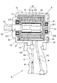
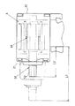
該気動工具モータAは、気動工具10の取っ手11の一端(本実施例では上部)の本体12内部に設けられる該気動工具モータAであり、該取っ手11は、その詳細が図3に示すように、吸気路111、排気路112と該吸気路111の開閉を制御するスイッチ113を備えてなるものである。
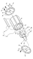
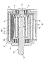
該気動工具モータAは、シリンダー体20と、回転子セット30と、収容室40と、出力軸50と、内蔵型打撃機構60と、少なくとも一つの駆動嵌込槽315と、を含む。
シリンダー体20は、前端壁21、後端壁22と、内部にある円筒状のシリンダー室23を備えてなる中空筐体のシリンダー体20であり、該前端壁21に前端軸受215、該後端壁22に後端軸受225が設けられている。
回転子セット30は、回転可能で、シリンダー体20のシリンダー室23内に設けられる回転子セット30であり、該回転子セット30は、回転子31、及び間隔を開けて回転子31の周壁に設置される複数の伸縮可能な羽根32を備えてなり、該回転子31は、前端板33と後端板34を備えてなり、該前端板33の中央部には、前端軸受215に取り付けるための前カム331、該後端板34の中央部には、後端軸受225に取り付けるための後カム341が設けられ、それに、伸縮可能な羽根32の外端はそれぞれ、移動可能で、シリンダー室23の内壁に突き当てるように設けられている。
収容室40は、回転子セット30の回転子31内部に設けられる収容室40であり、該収容室40は、円筒状のスペースに設けられてもよい。
出力軸50は、受動端51、外軸端52及び受動端51と外軸端52の間にある打撃作用セクション53を備えてなる出力軸50であり、該受動端51は、回転子セット30の回転子31にある後端板34に取り付けて固定され、出力軸50を回転子31の動きに伴い、同期に回転させるように設けられており、該外軸端52は、回転子31の前端板33にある前カム331を通って、更に気動工具10の本体12の前端外部に突き出すという順で設けられており、該打撃作用セクション53は、回転子31内の収容室40に設けられており、該受動端51と後端板34との組立、固定は、歯形部の噛合い、多辺形部の嵌め合い、または平らな切断面の組合せなどにより、具体的に行われるようになっている。
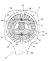
内蔵型打撃機構60は、回転子セット30の回転子31内の収容室40に内蔵され、出力軸50の打撃作用セクション53に突き出された少なくとも一つの打撃バンプ61、打撃バンプ61の外周に対応して設けられる少なくとも一つの可動ハンマー62、及び縦方向で、回転子の前、後端板33、34の間に配置され、可動ハンマー62への支持と位置決めを行うための少なくとも一つの支持柱63を備えてなる内蔵型打撃機構60であり、該収容室40内には、可動ハンマー62が活動できるための回避部64(図4のみに表示)が設けられている。
少なくとも一つの駆動嵌込槽315は、回転子31の収容室40内の少なくとも一つの側壁に凹設された少なくとも一つの駆動嵌込槽315(詳しくは図2、図4に示す)であり、該支持柱63の一部分がそこに嵌め込み、回転子31から支持柱63を同期に動かさせるように駆動するように設けられている。
該回転子31と伸縮可能な羽根32を備えてなる回転子セット30では、該回転子31と該前端板33、後端板34との間に対応して配置された締め付け穴71とボルト穴72があり、ボルト73がそれらに挿通、締め付けられるように設けられており、該ボルト73への締付け方向は、縦方向または横方向に設けられてもよく、図2に示すようなボルト73の場合、締め付け方向は、縦方向の実施例図で、図5に示すようなボルト73の場合、締め付け方向は、横方向の実施例図であり、また、該ボルト73の締め付け形態は、全部をボルト73で締付け、または一部分をボルト73で締付け、残りの一部分にピン74(図2)で差し込むように設けられている。
The pneumatic tool motor A is the pneumatic tool motor A provided inside the
The pneumatic tool motor A includes a
The
The
The
The
The built-in
At least one
In the rotor set 30 including the
該気動工具10は、気動スパナでもよく、該気動工具モータAは横向き方向で、取っ手11の上部に取り付けられ、該出力軸50の縦方向と取っ手11の伸ばされた方向とは相互に交錯し、または垂直な角度をなしているように設けられている。
The
上述した構造、組立て設計により、本発明の使用、作動状況について次のように名説明する。 Using the structure and assembly design described above, the use and operation status of the present invention will be described as follows.
本発明の該気動工具10のエア経路に関する操作は、従来のよく知られていることで、本発明の請求する範囲ではなく、ここで、概略のみを説明するが、図3に示すように、該気動工具10の立ち上げは、使用者がスイッチ113をオンして、吸気路111を開放することになっており、そうすると、空気圧(Wに示す)が気動工具モータAのシリンダー体20のシリンダー室23内へと流され、それによって、回転子セット30の伸縮可能な羽根32を動かし、回転子31と共に回転するようになり、その後、空気圧が排気路112を経て、外部へ排出されるという気動工具10の空気経路の操作流れである。
The operation related to the air path of the
本発明の中核的設計として、回転子セット30の回転子31内部に収容室40が設けられ、そこに該内蔵型打撃機構60が内蔵されている形態及び技術特徴を有することにあり、この特徴により、本発明は、直接に、回転子セット30の回転子31を該内蔵型打撃機構60の筐体として利用し、回転子31の収容室40の側壁に凹設された駆動嵌込槽315を、回転子31の支持柱63、内蔵型打撃機構60への駆動部位として設けられているから、本発明では、前述の従来の構造における“先端側のリバースケース”という部件を省いてもよく、それで、気動工具モータの縦方向の長さ、体積が顕著に小さくなり、それに関連する部品も小さくなること、その具体的な例として、図6に示すように、図中の(L1)で示されたセクションは、従来の気動工具における打撃機構の設置箇所、及びその突き出た長さで、図中の(L2)で示されたセクションは、本発明の気動工具における内蔵型打撃機構60の突き出た長さであり、両者を比較してよく分かるちょうに、本発明の気動工具にける取っ手前端の突き出た長さは、従来の場合に比べて、かなり短くなり、実際寸法は約3〜5センチが短縮可能(気動工具の仕様により異なる)。
The core design of the present invention is that the
該回転子セット30の回転子31に設けられる伸縮可能な羽根32数量は5枚以上で、該伸縮可能な羽根32数量の決定は、本発明の該内蔵型打撃機構60の技術特徴により行われるが、業界でよく知られているように、従来の気動工具における回転子セットの伸縮可能な羽根は通常、最大6枚配置されているが、本発明の回転子セット30では、該回転子31内部に更に収容室40が設けられ、そこに内蔵型打撃機構60を納めるのに供するため、該収容室40の最大スペースの要求を満たせるように、回転子31外部に設けられる伸縮可能な羽根32は、それぞれの横方向の高さが一般的な従来のものより低く設けられており、各伸縮可能な羽根32の横方向の高さの短縮に伴い、外に突き出す高さも短縮され、各空気圧縮空間の長さと高さとの割合に大きな差が生じることで、その問題を解決するため、伸縮可能な羽根32数量を増設することになっていること、一方、本発明は、各伸縮可能な羽根32の横方向の高さの短縮により、空気圧縮空間も縮小される心配もあるが、そこで、各伸縮可能な羽根32の縦方向の長さの割合を適当に増加して、その解決に対応するようになっている。
The number of
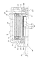
図7、図8に示すのは、該シリンダー体と回転子の構造形態のもう一つの実施例だが、本例では、該シリンダー体20Bと前端壁21(または後端壁22)との間は一体化した実施形態、または該シリンダー体と前端壁、後端壁との間は全部一体化した形態に設けられ、それに、シリンダー体の一箇所に、取外し可能な組立部(本例の図示は省略)が設けられ、図1に示すようにシリンダー体20と前、後端壁21、22との間を組立て、締め付けられてなる形態と異なる例であり、また、本例の回転子セット30Bにあっては、回転子31と前端板33(または後端板34)との間は一体化した実施形態であり、これも、図1に示すように、回転子セット30の回転子31と前、後端壁21、22との間を組立て、締め付けられてなる形態と異なる場合であり、なお、該シリンダー体20Bと前端壁21または後端壁22との間、及び回転子31と前端板33または後端板34との間は組立てなる形態だが、ボルト締め付け、または単なる張り合わせにして、最後に、本体12の端壁との組立て、締め付けを行って固定してもよく、または、該回転子セットの回転子と前端板、後端板との間を一体化にした形態に設けられると同時に、回転子の一箇所に、取外し可能な組立部(本例の図示は省略)が設けられている。
7 and 8 show another embodiment of the structure of the cylinder body and the rotor. In this example, the space between the
本発明に掲示した「打撃機構内蔵の気動工具モータ」は、該回転子セットの回転子内部に収容室、及び該収容室に打撃作用セクションを備えてなる出力軸、そして、該収容室中に内蔵された該内蔵型打撃機構を備えてなるオリジナルな構造形態であり、本発明は、背景技術に述べてある従来の構造に対して、回転子セットの回転子内部に内蔵された打撃機構を有する新式気動工具モータ形態を提供し、気動工具モータの縦方向の長さ、体積を大幅に削減でき、そうすると、気動工具の出力軸の外軸端と取っ手との間に突き出た長さが顕著に短縮され、使用の時、あまり力をかけずに操作でき、使いやすくなるというメリットと進歩性、そして、打撃機構は、回転子セットで直接に駆動され、トルクが瞬間的に上がり、それに部品の取外し・取り付けが簡単にスピーデで行われるという利便性があるという長所があること、その上、製造面にあっては、本発明では、回転子セットの回転子内部に打撃機構が内蔵されていることを特徴とし、気動工具モータの縦方向の長さ、体積が顕著に短縮可能で、それに関連する部品も小さくなり、気動工具モータの材料、製造、組立や包装などのコストが大幅に削減できるという産業上の経済的効果がある。 The “pneumatic tool motor with a built-in striking mechanism” posted in the present invention includes a housing chamber inside the rotor of the rotor set, an output shaft having a striking action section in the housing chamber, The present invention is an original structural form including the built-in striking mechanism built in the present invention, and the present invention is a striking mechanism built into the rotor of the rotor set with respect to the conventional structure described in the background art. A pneumatic tool motor configuration having a pneumatic tool motor can be provided, and the longitudinal length and volume of the pneumatic tool motor can be greatly reduced, so that it protrudes between the outer shaft end of the output shaft of the pneumatic tool and the handle. The length is remarkably shortened, and it can be operated with little force when used, and it is easy to use and has the inventive step and the striking mechanism is driven directly by the rotor set, and the torque is instantaneous And remove / remove parts In addition, there is an advantage that the attachment can be performed easily and speedily, and in addition, in terms of manufacturing, in the present invention, a striking mechanism is built in the rotor of the rotor set. The feature is that the vertical length and volume of the pneumatic tool motor can be remarkably shortened, and the parts related to it can be reduced, greatly reducing the cost of pneumatic tool motor materials, manufacturing, assembly and packaging. There are industrial economic effects.
上述した実施例に掲示したのは、本発明を具体的に説明する内容であり、文の中で専門的な用語で説明してきたが、それらを以て、本発明の特許請求範囲を制限してはならないとし、この技術分野がよく分かる者は、本発明のコンセプトや考えなどを理解したうえ、その変更や改造などを行って、それと同等な効果を得たとしても、それらの変更や改造などはすべて、後述の特許請求範囲に含まれるものとする。 What has been posted in the above-described embodiments is a specific description of the present invention, and has been described in technical terms in the text. However, the claims of the present invention should not be limited thereby. If you understand this technical field well, understand the concept and idea of the present invention, and make changes or modifications, and even if you get the same effect, those changes and modifications etc. All are intended to be included in the scope of the claims that follow.
気動工具モータ A
気動工具 10
取っ手 11
吸気路 111
排気路 112
スイッチ 113
本体 12
シリンダー体 20、20B
前端壁 21
前端軸受 215
後端壁 22
後端軸受 225
シリンダー室 23
回転子セット 30、30B
回転子 31
駆動嵌込槽 315
伸縮可能な羽根 32
前端板 33
前カム 331
後端板 34
後カム 341
収容室 40
出力軸 50
受動端 51
外軸端 52
打撃作用セクション 53
内蔵型打撃機構 60
打撃バンプ 61
可動ハンマー 62
支持柱 63
回避部 64
締め付け穴 71
ボルト穴 72
ボルト 73
ピン 74
Pneumatic tool motor A
Front end bearing 215
Rotor set 30, 30B
Drive
Built-in
Tightening
Claims (5)
該気動工具モータ(A)は、
前端壁(21)、後端壁(22)と、内部にある円筒状のシリンダー室(23)を備えてなる中空筐体のシリンダー体(20)であって、該前端壁(21)に前端軸受(215)、該後端壁(22)に後端軸受(225)が設けられている、シリンダー体(20)と、
回転可能で、シリンダー体(20)のシリンダー室(23)内に設けられる回転子セット(30)であって、該回転子セット(30)は、回転子(31)、及び間隔を開けて回転子(31)の周壁に設置される複数の伸縮可能な羽根(32)を備えてなり、該回転子(31)は、前端板(33)と後端板(34)を備えてなり、該前端板(33)の中央部には、前端軸受(215)に取り付けるための前カム(331)、該後端板(34)の中央部には、後端軸受(225)に取り付けるための後カム(341)が設けられ、それに、伸縮可能な羽根(32)の外端はそれぞれ、移動可能で、シリンダー室(23)の内壁に突き当てるように設けられている、回転子セット(30)と、
回転子セット(30)の回転子(31)内部に設けられる収容室(40)と、
受動端(51)、外軸端(52)及び受動端(51)と外軸端(52)の間にある打撃作用セクション(53)を備えてなる出力軸(50)であって、該受動端(51)は、回転子セット(30)の回転子(31)にある後端板(34)に取り付けて固定され、出力軸(50)を回転子(31)の動きに伴い、同期に回転させるように設けられており、該外軸端(52)は、回転子(31)の前端板(33)にある前カム(331)を通って、更に気動工具(10)の本体(12)の前端外部に突き出すという順で設けられており、該打撃作用セクション(53)は、回転子(31)内の収容室(40)に設けられている、出力軸(50)と、
回転子セット(30)の回転子(31)内の収容室(40)に内蔵され、出力軸(50)の打撃作用セクション(53)に突き出された少なくとも一つの打撃バンプ(61)、打撃バンプ(61)の外周に対応して設けられる少なくとも一つの可動ハンマー(62)、及び縦方向で、回転子の前、後端板(33、34)の間に配置され、可動ハンマー(62)への支持と位置決めを行うための少なくとも一つの支持柱(63)を備えてなる内蔵型打撃機構(60)であって、該収容室(40)内には、可動ハンマー(62)が活動できるための回避部(64)が設けられている、内蔵型打撃機構(60)と、
回転子(31)の収容室(40)内の少なくとも一つの側壁に凹設された少なくとも一つの駆動嵌込槽(315)であって、該支持柱(63)の一部分がそこに嵌め込み、回転子(31)から支持柱(63)を同期に動かさせるように駆動するように設けられている、少なくとも一つの駆動嵌込槽(315)と、を含み、
それにより、回転子セット(30)の回転子(31)内部に内蔵された打撃機構を有する気動工具モータ(A)構造形態を提供し、気動工具モータ(A)の縦方向の長さ、体積を大幅に削減できるように設けられていることを特徴とする打撃機構内蔵の気動工具モータ。 The pneumatic tool motor (A) provided inside one end (12) of the handle (11) of the pneumatic tool (10), wherein the handle (11) includes an intake passage (111) and an exhaust passage (112). ) And a switch (113) that controls opening and closing of the intake passage (111),
The pneumatic tool motor (A)
A cylinder body (20) of a hollow housing comprising a front end wall (21), a rear end wall (22), and an internal cylindrical cylinder chamber (23), wherein the front end wall (21) has a front end A cylinder body (20) having a bearing (215) and a rear end bearing (225) provided on the rear end wall (22);
A rotor set (30) that is rotatable and is provided in a cylinder chamber (23) of a cylinder body (20), the rotor set (30) rotating at a distance between a rotor (31) and an interval. The rotor (31) includes a front end plate (33) and a rear end plate (34). The rotor (31) includes a plurality of extendable blades (32) installed on the peripheral wall of the child (31). A front cam (331) for attaching to the front end bearing (215) is provided at the center of the front end plate (33), and a rear for attaching to the rear end bearing (225) is provided at the center of the rear end plate (34). The rotor set (30) is provided with a cam (341), and the outer ends of the extendable blades (32) are movable and are provided to abut against the inner wall of the cylinder chamber (23). When,
A storage chamber (40) provided inside the rotor (31) of the rotor set (30);
An output shaft (50) comprising a passive end (51), an outer shaft end (52) and a striking action section (53) between the passive end (51) and the outer shaft end (52), The end (51) is fixedly attached to the rear end plate (34) of the rotor (31) of the rotor set (30), and the output shaft (50) is synchronized with the movement of the rotor (31). The outer shaft end (52) passes through the front cam (331) on the front end plate (33) of the rotor (31) and further passes through the main body (10) of the pneumatic tool (10). 12) is provided in the order of projecting to the outside of the front end, and the striking action section (53) includes an output shaft (50) provided in a storage chamber (40) in the rotor (31),
At least one striking bump (61), striking bump, which is built into the accommodating chamber (40) in the rotor (31) of the rotor set (30) and protrudes to the striking action section (53) of the output shaft (50). At least one movable hammer (62) provided corresponding to the outer periphery of (61), and disposed in the longitudinal direction between the front and rear end plates (33, 34) of the rotor, to the movable hammer (62) A built-in striking mechanism (60) having at least one support column (63) for supporting and positioning the movable hammer (62) in the accommodating chamber (40). A built-in striking mechanism (60) provided with an avoidance part (64) of
At least one drive fitting tank (315) recessed in at least one side wall in the accommodating chamber (40) of the rotor (31), and a part of the support column (63) is fitted therein to rotate. And at least one drive fitting tub (315) provided to drive the support column (63) to move synchronously from the child (31),
Thereby, a pneumatic tool motor (A) structure form having a striking mechanism built in the rotor (31) of the rotor set (30) is provided, and the longitudinal length of the pneumatic tool motor (A) is provided. A pneumatic tool motor with a built-in striking mechanism, characterized in that the volume can be greatly reduced.
Priority Applications (1)
| Application Number | Priority Date | Filing Date | Title |
|---|---|---|---|
| JP2013151246A JP6133157B2 (en) | 2013-07-22 | 2013-07-22 | Pneumatic tool motor with built-in striking mechanism |
Applications Claiming Priority (1)
| Application Number | Priority Date | Filing Date | Title |
|---|---|---|---|
| JP2013151246A JP6133157B2 (en) | 2013-07-22 | 2013-07-22 | Pneumatic tool motor with built-in striking mechanism |
Publications (2)
| Publication Number | Publication Date |
|---|---|
| JP2015020249A true JP2015020249A (en) | 2015-02-02 |
| JP6133157B2 JP6133157B2 (en) | 2017-05-24 |
Family
ID=52485179
Family Applications (1)
| Application Number | Title | Priority Date | Filing Date |
|---|---|---|---|
| JP2013151246A Expired - Fee Related JP6133157B2 (en) | 2013-07-22 | 2013-07-22 | Pneumatic tool motor with built-in striking mechanism |
Country Status (1)
| Country | Link |
|---|---|
| JP (1) | JP6133157B2 (en) |
Citations (7)
| Publication number | Priority date | Publication date | Assignee | Title |
|---|---|---|---|---|
| JPS6426163U (en) * | 1987-08-05 | 1989-02-14 | ||
| JP2002266601A (en) * | 2001-03-13 | 2002-09-18 | Youtarou Taga | Motor for air impact wrench |
| US20060157261A1 (en) * | 2005-01-18 | 2006-07-20 | Tranmax Machinery Co., Ltd. | Double-ram striker assembly |
| US20080283259A1 (en) * | 2006-09-22 | 2008-11-20 | Chen Chi-Chen | Pneumatic hand tool |
| JP2009184042A (en) * | 2008-02-05 | 2009-08-20 | Hitachi Koki Co Ltd | Rotating hammer tool |
| US20110083869A1 (en) * | 2009-10-13 | 2011-04-14 | Chen-Yang Lin | Quick assembly pneumatic tool |
| JP2013000869A (en) * | 2011-06-21 | 2013-01-07 | Vessel Fukuchiyama:Kk | Rotary tool |
-
2013
- 2013-07-22 JP JP2013151246A patent/JP6133157B2/en not_active Expired - Fee Related
Patent Citations (7)
| Publication number | Priority date | Publication date | Assignee | Title |
|---|---|---|---|---|
| JPS6426163U (en) * | 1987-08-05 | 1989-02-14 | ||
| JP2002266601A (en) * | 2001-03-13 | 2002-09-18 | Youtarou Taga | Motor for air impact wrench |
| US20060157261A1 (en) * | 2005-01-18 | 2006-07-20 | Tranmax Machinery Co., Ltd. | Double-ram striker assembly |
| US20080283259A1 (en) * | 2006-09-22 | 2008-11-20 | Chen Chi-Chen | Pneumatic hand tool |
| JP2009184042A (en) * | 2008-02-05 | 2009-08-20 | Hitachi Koki Co Ltd | Rotating hammer tool |
| US20110083869A1 (en) * | 2009-10-13 | 2011-04-14 | Chen-Yang Lin | Quick assembly pneumatic tool |
| JP2013000869A (en) * | 2011-06-21 | 2013-01-07 | Vessel Fukuchiyama:Kk | Rotary tool |
Also Published As
| Publication number | Publication date |
|---|---|
| JP6133157B2 (en) | 2017-05-24 |
Similar Documents
| Publication | Publication Date | Title |
|---|---|---|
| US9545708B2 (en) | Pneumatic motor with built-in striker mechanism | |
| JP6519651B2 (en) | Driving machine | |
| JP6579197B2 (en) | Reciprocating machine | |
| US10525577B2 (en) | Power tool | |
| TWI591257B (en) | Rotating mechanism of an air compressor | |
| JP2008023653A5 (en) | ||
| TWI421152B (en) | Built-in pneumatic mechanism motor with hitting mechanism | |
| CN204913814U (en) | Multi -functional electric hammer structure | |
| JP6133157B2 (en) | Pneumatic tool motor with built-in striking mechanism | |
| JP2008183683A (en) | Electric tool | |
| CN204505133U (en) | There is the pneumatic tool of two impact block impact group | |
| TWI522212B (en) | Pneumatic tools with double impact block impact | |
| CN104175269B (en) | Air tool motor with built-in striking mechanism | |
| EP2823939A2 (en) | Pneumatic motor with built-in striker mechanism | |
| JP4750437B2 (en) | Fastener | |
| CN201604027U (en) | Side surface overturning clamp for pass axle box | |
| JP6160771B2 (en) | Hammering machine | |
| JP2010269424A (en) | Oil pulse tool | |
| JP2024017590A (en) | work equipment | |
| JP2015120206A (en) | Impact tool | |
| CN207326893U (en) | Electric impac tool | |
| TW201706084A (en) | Pneumatic tool motor having an internal hammering device | |
| CN205765998U (en) | A kind of integral type multiple bit screwdriver | |
| JP2533769B2 (en) | Hammer drill | |
| KR101566845B1 (en) | Oscillating actuator |
Legal Events
| Date | Code | Title | Description |
|---|---|---|---|
| A621 | Written request for application examination |
Free format text: JAPANESE INTERMEDIATE CODE: A621 Effective date: 20160407 |
|
| A977 | Report on retrieval |
Free format text: JAPANESE INTERMEDIATE CODE: A971007 Effective date: 20170223 |
|
| TRDD | Decision of grant or rejection written | ||
| A01 | Written decision to grant a patent or to grant a registration (utility model) |
Free format text: JAPANESE INTERMEDIATE CODE: A01 Effective date: 20170328 |
|
| A61 | First payment of annual fees (during grant procedure) |
Free format text: JAPANESE INTERMEDIATE CODE: A61 Effective date: 20170419 |
|
| R150 | Certificate of patent or registration of utility model |
Ref document number: 6133157 Country of ref document: JP Free format text: JAPANESE INTERMEDIATE CODE: R150 |
|
| LAPS | Cancellation because of no payment of annual fees |