JP2015019799A - Water heating container - Google Patents
Water heating container Download PDFInfo
- Publication number
- JP2015019799A JP2015019799A JP2013149569A JP2013149569A JP2015019799A JP 2015019799 A JP2015019799 A JP 2015019799A JP 2013149569 A JP2013149569 A JP 2013149569A JP 2013149569 A JP2013149569 A JP 2013149569A JP 2015019799 A JP2015019799 A JP 2015019799A
- Authority
- JP
- Japan
- Prior art keywords
- water stop
- spout
- water
- steam
- storage chamber
- Prior art date
- Legal status (The legal status is an assumption and is not a legal conclusion. Google has not performed a legal analysis and makes no representation as to the accuracy of the status listed.)
- Pending
Links
Images


Landscapes
- Cookers (AREA)
Abstract
Description
本発明は、上方側が開口し、内部に貯留部を有する有底筒状の容器本体と、容器本体の上方開口部を密封状態で閉鎖可能な蓋体と、容器本体に設けられるハンドルと、貯留部内の水を加熱する加熱機構と、蓋体により密封された貯留部と注ぎ口とを連通し、貯留部内の水を注ぎ口を介して外部に通流させる注出流路と、注出流路に設けられ、注出流路を密封状態で閉鎖可能な弁機構と、蓋体により密封された貯留部と蒸気排出口とを連通し、貯留部内の水から発生する蒸気を蒸気排出口を介して外部に通流させる蒸気流路とを備えた水加熱容器に関する。 The present invention relates to a bottomed cylindrical container body having an opening on the upper side and having a storage section therein, a lid body capable of closing the upper opening section of the container body in a sealed state, a handle provided on the container body, A heating mechanism for heating the water in the section, a storage section sealed by a lid and a spout, and a water flow in the storage section to the outside through the spout; The valve mechanism that is provided in the channel and can close the discharge channel in a sealed state, and the storage section sealed by the lid and the steam discharge port communicate with each other, and steam generated from the water in the storage section is connected to the steam discharge port. It is related with the water heating container provided with the steam flow path which lets it flow outside through.
この種の水加熱容器としては、電気ケトルや電気ポット等が例示できるが、上面視で、容器本体の前後方向において、前側に注ぎ口を設け、注ぎ口の反対側である後側にハンドルを設けた構成が開示されている(特許文献1参照)。
これにより、使用者がハンドルを把持し、注ぎ口がハンドルよりも下側に位置するように容器本体を傾斜させることで、加熱機構により加熱された貯留部内の湯水を、注出流路、開操作された弁機構及び注ぎ口を介して外部に注出することができる。
Examples of this type of water heating container include an electric kettle and an electric kettle. The provided structure is disclosed (see Patent Document 1).
As a result, the user grips the handle and tilts the container body so that the spout is located below the handle. It can be poured out via the operated valve mechanism and spout.
又、この種の水加熱容器では、蒸気流路には、鉛直方向に対する容器本体の軸心の傾斜角度に応じて、当該傾斜角度が所定の止水用角度以上(例えば、鉛直方向に対して90度以上)となった場合に蒸気流路を閉鎖する止水状態と、当該傾斜角度が所定の止水用角度未満の場合には蒸気流路を開放する止水解除状態とに切換え可能な錘体を有する転倒止水弁が設けられている。
これにより、容器本体がテーブル等に載置されて容器本体の軸心が鉛直方向と略平行な正立姿勢では、蒸気流路を開放する止水解除状態として、貯留部内の湯水から発生した蒸気を蒸気流路の蒸気排出口を介して外部に排出することができ、しかも、鉛直方向に対する容器本体の軸心の傾斜角度が所定の止水用角度以上(例えば、容器本体が転倒等した場合等)となった傾斜姿勢では、蒸気流路を閉鎖する止水状態として、貯留部内の湯水が蒸気流路の蒸気排出口から漏出することを防止できるとされている。
Further, in this type of water heating vessel, the steam flow path has an inclination angle equal to or greater than a predetermined water stop angle (for example, with respect to the vertical direction) according to the inclination angle of the axis of the vessel body with respect to the vertical direction. 90 ° or more), and can be switched between a water stop state in which the steam flow path is closed and a water stop release state in which the steam flow path is opened when the inclination angle is less than a predetermined water stop angle. An overturn stop valve having a weight body is provided.
As a result, when the container body is placed on a table or the like and the upright posture in which the axis of the container body is substantially parallel to the vertical direction, the steam generated from the hot water in the storage unit is brought into a water-released state in which the steam channel is opened. Can be discharged to the outside through the steam outlet of the steam flow path, and the inclination angle of the axis of the container body with respect to the vertical direction is equal to or greater than a predetermined water stop angle (for example, the container body falls down) Etc.), it is said that the hot water in the reservoir can be prevented from leaking from the steam outlet of the steam channel as a water-stopping state in which the steam channel is closed.
ここで、上述の水加熱容器では、内部に貯留部を有する容器本体の上方開口部が、蓋体により密封状態で閉鎖され、注出流路も弁機構により密封状態で閉鎖されるように構成されている。一方で、蒸気流路は、容器本体が傾斜姿勢となった場合、即ち、容器本体の軸心が鉛直方向に対して所定の止水用角度以上傾斜した場合には、転倒止水弁の錘体により閉鎖されるように構成されている。
従って、使用者がハンドルを把持し、貯留部内の湯水を注ぎ口を介して外部に注出しようとして、注ぎ口がハンドルよりも下側に位置するように容器本体の軸心を鉛直方向に対して傾斜させた際には、その傾斜角度が所定の止水用角度以上であれば、蒸気流路が転倒止水弁の錘体により閉鎖されることとなる。
Here, the above-mentioned water heating container is configured such that the upper opening of the container main body having a storage portion inside is closed in a sealed state by a lid, and the dispensing flow path is also closed in a sealed state by a valve mechanism. Has been. On the other hand, when the container main body is inclined, that is, when the axis of the container main body is inclined more than a predetermined water-stop angle with respect to the vertical direction, the steam flow path has a weight of the falling water stop valve. It is configured to be closed by the body.
Therefore, the user grips the handle, and tries to pour hot water in the reservoir through the spout, and the axis of the container body is perpendicular to the vertical direction so that the spout is located below the handle. If the inclination angle is equal to or greater than a predetermined water stop angle, the steam flow path is closed by the weight body of the overturn stop valve.
このように、容器本体が傾斜姿勢となり、弁機構が注出流路を密封状態で閉鎖したままの状態で転倒止水弁の錘体により蒸気流路が閉鎖されてしまうと、貯留部内は密封された空間となり、容器本体の貯留部内に高温の湯水が貯留されている場合(例えば、加熱機構による加熱が完了した直後等)には、貯留部内の湯水から発生した蒸気により貯留部内の内圧が上昇することとなる。
そして、貯留部内の内圧が上昇した状況で、使用者が弁機構を開操作すると、注出流路や貯留部に存在する高温の湯水が注ぎ口から勢いよく外部に突出する虞があり、注ぎ口から突出した高温の湯水により不測の事態を招来する虞がある。
As described above, if the steam flow path is closed by the weight of the overturn stop valve while the container body is inclined and the valve mechanism is closed in the sealed state, the storage section is sealed. When the hot water is stored in the storage part of the container body (for example, immediately after the heating by the heating mechanism is completed), the internal pressure in the storage part is caused by the steam generated from the hot water in the storage part. Will rise.
When the user opens the valve mechanism in a situation where the internal pressure in the storage portion has increased, there is a risk that hot hot water existing in the discharge flow path or the storage portion may protrude vigorously from the spout. There is a risk of unforeseen circumstances due to hot hot water protruding from the mouth.
本発明は、上述の実情に鑑みて為されたものであり、その主たる課題は、蒸気流路に転倒止水弁を設けた場合において、容器本体を傾斜させて注ぎ口から湯水を注出する際に、貯留部の内圧の上昇を防止でき、湯水が注ぎ口から勢いよく突出することを防止できる水加熱容器を提供する点にある。 The present invention has been made in view of the above-described circumstances, and the main problem is that when a tipping water stop valve is provided in the steam channel, the container body is inclined to pour hot water from the spout. In this case, it is to provide a water heating container that can prevent an increase in the internal pressure of the reservoir and prevent hot water from protruding vigorously from the spout.
上記目的を達成するための本発明に係る水加熱容器は、上方側が開口し、内部に貯留部を有する有底筒状の容器本体と、前記容器本体の上方開口部を密封状態で閉鎖可能な蓋体と、前記容器本体に設けられるハンドルと、前記貯留部内の水を加熱する加熱機構と、前記蓋体により密封された前記貯留部と注ぎ口とを連通し、前記貯留部内の水を前記注ぎ口を介して外部に通流させる注出流路と、前記注出流路に設けられ、前記注出流路を密封状態で閉鎖可能な弁機構と、前記蓋体により密封された前記貯留部と蒸気排出口とを連通し、前記貯留部内の水から発生する蒸気を前記蒸気排出口を介して外部に通流させる蒸気流路とを備えた水加熱容器であって、その特徴構成は、
前記注ぎ口が、上面視で、前記容器本体及び前記蓋体の中央部に対して外周側の位置に設けられ、
前記蒸気流路には、鉛直方向に対する前記容器本体の軸心の傾斜角度に応じて誘導壁に沿って移動可能で、且つ、当該移動により前記蒸気流路を閉鎖する止水状態と前記蒸気流路を開放する止水解除状態とに切換え可能な止水部材を有する転倒止水弁が設けられ、
前記蒸気流路の前記注ぎ口側には、前記止水部材が前記止水解除状態から前記止水状態となるのを阻止する邪魔部が設けられている点にある。
In order to achieve the above object, a water heating container according to the present invention is capable of closing a bottomed cylindrical container body having an opening on the upper side and having a storage part inside, and the upper opening of the container body in a sealed state. A lid, a handle provided in the container body, a heating mechanism for heating water in the reservoir, and the reservoir and the spout sealed by the lid communicate with each other, and the water in the reservoir is A pour-out passage through which the pour-out opening is made to flow; a valve mechanism provided in the pour-out passage and capable of closing the pour-out passage in a sealed state; and the storage sealed by the lid A water heating container having a steam flow path for communicating steam generated from the water in the storage section to the outside through the steam discharge port, the water heating container communicating with the portion and the steam discharge port. ,
The pouring spout is provided at a position on the outer peripheral side with respect to the central part of the container body and the lid body in a top view,
The steam flow path is movable along the guide wall according to the inclination angle of the axis of the container main body with respect to the vertical direction, and the steam flow is closed by closing the steam flow path by the movement. A falling water stop valve having a water stop member that can be switched to a water stop release state that opens the path is provided,
The steam channel is provided with a baffle portion that prevents the water stop member from entering the water stop state from the water stop release state on the spout side.
上記特徴構成によれば、基本的に、上方側が開口し、内部に貯留部を有する有底筒状の容器本体と、容器本体の上方開口部を密封状態で閉鎖可能な蓋体と、容器本体に設けられるハンドルと、蓋体により密封された貯留部と注ぎ口とを連通し、貯留部内の水を注ぎ口を介して外部に通流させる注出流路とを備え、注ぎ口が、上面視で容器本体及び蓋体の中央部に対して外周側の位置に設けられているので、使用者がハンドルを把持し、容器本体を注ぎ口側が下側に位置するように傾斜させて、貯留部内の湯水を、開操作された弁機構、注出流路及び注ぎ口を介して外部に注出させることができる。 According to the above characteristic configuration, basically, a bottomed cylindrical container body having an opening on the upper side and having a storage portion therein, a lid body capable of closing the upper opening of the container body in a sealed state, and the container body And a pour spout that communicates the water in the reservoir to the outside through the pour spout. Since it is provided at a position on the outer peripheral side with respect to the central part of the container main body and the lid body, the user holds the handle and tilts the container main body so that the spout side is located on the lower side for storage. The hot water in the section can be poured out through the opened valve mechanism, the pouring channel and the spout.
又、蓋体により密封された貯留部と蒸気排出口とを連通し、貯留部内の水から発生する蒸気を蒸気排出口を介して外部に通流させる蒸気流路には、鉛直方向に対する容器本体の軸心の傾斜角度に応じて誘導壁に沿って移動可能で、且つ、当該移動により蒸気流路を閉鎖する止水状態と蒸気流路を開放する止水解除状態とに切換え可能な止水部材を有する転倒止水弁が設けられている。
これにより、鉛直方向に対する容器本体の軸心の傾斜角度に応じて、止水部材を誘導壁に沿って案内した状態で移動させることができ、止水状態と止水解除状態との切換えを安定して行うことができる。従って、容器本体が傾斜姿勢となった場合に、蒸気流路を閉鎖して、蒸気流路からの湯水の漏出を防止でき、容器本体が正立姿勢の場合に、蒸気流路を開放して、蒸気流路からの蒸気の排出を行うことができるという、転倒止水弁の基本的機能を安定的に発揮することができる。
In addition, a container body with respect to the vertical direction is provided in a steam flow path that connects the storage part sealed by the lid and the steam discharge port and allows the steam generated from the water in the storage part to flow outside through the steam discharge port. The water stoppage that can be moved along the guide wall according to the inclination angle of the shaft center and can be switched between a waterstop state that closes the steam flow path and a water stop release state that opens the steam flow path by the movement. An overturn stop valve having a member is provided.
Thereby, according to the inclination angle of the axis of the container main body with respect to the vertical direction, the water stop member can be moved in a state of being guided along the guide wall, and switching between the water stop state and the water stop release state is stable. Can be done. Therefore, when the container body is tilted, the steam channel can be closed to prevent leakage of hot water from the steam channel, and when the container body is in the upright position, the steam channel is opened. In addition, the basic function of the overturning water stop valve that can discharge steam from the steam flow path can be stably exhibited.
特に、蒸気流路の注ぎ口側には、止水部材が止水解除状態から止水状態となるのを阻止する邪魔部が設けられている。
これにより、使用者がハンドルを把持し、貯留部内の湯水を注ぎ口を介して外部に注出しようとして、注ぎ口が下側に位置するように容器本体の軸心を鉛直方向に対して傾斜させた傾斜姿勢とした際、蒸気流路の注ぎ口側に位置する邪魔部により、止水部材が止水解除状態から止水状態となるのが阻止され、止水部材は止水解除状態のまま維持され、蒸気流路が閉鎖されないこととなる。
即ち、容器本体を注ぎ口が下側となる状態で傾斜姿勢としても、貯留部と蒸気排出口(外部(例えば、大気圧程度))とを連通した状態が維持され、貯留部内の湯水から発生した蒸気を蒸気排出口を介して外部に排出することができる。従って、容器本体を注ぎ口が下側となる状態で傾斜姿勢として注ぎ口を介して湯水を注出する際、貯留部内の内圧が上昇することを防止でき、弁機構を開操作しても注出流路の注ぎ口から湯水が突出することを防止できる。
In particular, a baffle portion is provided on the spout side of the steam channel to prevent the water stop member from entering the water stop state from the water stop release state.
As a result, the user grips the handle and tries to pour the hot water in the reservoir through the spout, and the axis of the container body is inclined with respect to the vertical direction so that the spout is located on the lower side. When the inclined posture is set, the baffle portion located on the spout side of the steam channel prevents the water stop member from entering the water stop state from the water stop release state, and the water stop member is in the water stop release state. The steam flow path is not closed.
In other words, even when the container body is inclined with the spout on the bottom, the state where the reservoir and the steam outlet (external (for example, about atmospheric pressure)) communicate with each other is maintained and is generated from the hot water in the reservoir. The discharged steam can be discharged to the outside through the steam discharge port. Therefore, when pouring hot water through the spout with the container body in an inclined posture with the spout on the lower side, it is possible to prevent the internal pressure in the reservoir from rising, even if the valve mechanism is opened. It is possible to prevent hot water from protruding from the spout of the outlet channel.
加えて、邪魔部が、蒸気流路において注ぎ口側に位置するように設けられている(注ぎ口側に位置しない蒸気流路には、邪魔部は設けられていない)ので、容器本体が転倒等して、注ぎ口が下側に位置しない状態で容器本体の軸心が鉛直方向に対して傾斜した傾斜姿勢となった際には、止水部材は誘導壁に沿って止水解除状態から止水状態となって、蒸気流路を閉鎖することができる。 In addition, since the baffle part is provided so as to be located on the spout side in the steam channel (the baffle part is not provided in the steam channel not located on the spout side), the container body falls over. In the case where the pouring spout is not positioned on the lower side and the axis of the container body is inclined with respect to the vertical direction, the water stop member is moved from the water stop release state along the guide wall. It becomes a water stop state and can close a steam channel.
よって、蒸気流路に転倒止水弁を設けた場合において、転倒止水弁の基本的な機能を維持しながら、容器本体を傾斜させて注ぎ口から湯水を注出する際に、貯留部の内圧の上昇を防止でき、湯水が注ぎ口から勢いよく突出することを防止できる水加熱容器を提供できた。 Therefore, in the case where a tip-over water valve is provided in the steam channel, while maintaining the basic function of the tip-over water valve, when the hot water is poured from the spout while the container body is inclined, The water heating container which can prevent a raise of internal pressure and can prevent hot water from protruding from a spout vigorously was provided.
本発明に係る水加熱容器の更なる特徴構成は、前記止水部材が、前記傾斜角度が所定の止水用角度以上となった場合に前記止水状態となり、前記傾斜角度が前記所定の止水用角度未満の場合には前記止水解除状態となるように構成され、
前記容器本体の軸心を前記注ぎ口側が下側に位置するように傾斜させた場合において、前記傾斜角度が前記所定の止水用角度以上且つ所定の邪魔用角度以下の邪魔用角度範囲内にあるときに、前記邪魔部が、前記止水部材が前記止水解除状態から前記止水状態となるのを阻止するように構成されている点にある。
According to a further characteristic configuration of the water heating container according to the present invention, the water stop member enters the water stop state when the inclination angle is equal to or greater than a predetermined water stop angle, and the inclination angle is the predetermined stop. If it is less than the angle for water, it is configured to be in the water stop release state,
In the case where the axis of the container body is inclined so that the spout side is positioned on the lower side, the inclination angle is within the baffle angle range not less than the predetermined water stop angle and not greater than the predetermined baffle angle. In some cases, the baffle portion is configured to prevent the water stop member from entering the water stop state from the water stop release state.
上記特徴構成によれば、止水部材が、当該傾斜角度が所定の止水用角度以上となった場合に止水状態となり、当該傾斜角度が所定の止水用角度未満の場合には止水解除状態となるように構成されている。
従って、鉛直方向に対する容器本体の軸心の傾斜角度が所定の止水用角度以上の傾斜姿勢となった場合に、蒸気流路を閉鎖して、蒸気流路からの湯水の漏出を防止でき、当該傾斜角度が所定の止水用角度未満の正立姿勢の場合に、蒸気流路を開放して、蒸気流路からの蒸気の排出を行うことができるという、転倒止水弁の基本的機能を安定的に発揮することができる。なお、所定の止水用角度は、鉛直方向に対して容器本体の軸心が傾斜した傾斜姿勢となり、貯留部内の湯水が蒸気流路の通流を開始する前後の傾斜角度程度に設定することができる。
According to the above characteristic configuration, the water stop member enters a water stop state when the inclination angle is equal to or greater than the predetermined water stop angle, and the water stop member when the inclination angle is less than the predetermined water stop angle. It is comprised so that it may be in a cancellation | release state.
Therefore, when the inclination angle of the axis of the container main body with respect to the vertical direction is an inclination posture equal to or greater than a predetermined water stop angle, the steam flow path can be closed to prevent leakage of hot water from the steam flow path, The basic function of the overturn stop valve is that the steam flow path can be opened and steam can be discharged from the steam flow path when the inclination angle is less than the predetermined water stop angle. Can be stably exhibited. The predetermined water stop angle is set to an inclination angle before and after the axial center of the container main body is inclined with respect to the vertical direction and the hot water in the reservoir starts flowing through the steam channel. Can do.
特に、容器本体の軸心を注ぎ口側が下側に位置するように傾斜させた場合において、傾斜角度が所定の止水用角度以上且つ所定の邪魔用角度以下の邪魔用角度範囲内にあるときに、邪魔部が、止水部材が止水解除状態から止水状態となるのを阻止するように構成されている。
これにより、使用者がハンドルを把持し、貯留部内の湯水を注ぎ口を介して外部に注出しようとして、注ぎ口が下側に位置するように容器本体の軸心を鉛直方向に対して傾斜させた傾斜姿勢とした際、その傾斜角度が所定の止水用角度以上であっても所定の邪魔用角度以下の邪魔用角度範囲内であれば、蒸気流路の注ぎ口側に位置する邪魔部により、止水部材が止水解除状態から止水状態となるのが阻止され、止水部材は止水解除状態のまま維持され、蒸気流路が閉鎖されないこととなる。
即ち、容器本体を注ぎ口が下側となる状態で傾斜姿勢としても、傾斜角度が邪魔用角度範囲内であれば、貯留部と蒸気排出口(外部(例えば、大気圧程度))とを連通した状態が維持され、貯留部内の湯水から発生した蒸気を蒸気排出口を介して外部に排出することができる。従って、容器本体を注ぎ口が下側となる状態で傾斜姿勢として注ぎ口を介して湯水を注出する際、貯留部内の内圧が上昇することを防止でき、弁機構を開操作しても注出流路の注ぎ口から湯水が突出することを防止できる。
In particular, when the axis of the container body is tilted so that the spout side is located on the lower side, the tilt angle is within a baffle angle range that is not less than a predetermined water stop angle and not greater than a predetermined baffle angle. In addition, the baffle portion is configured to prevent the water stop member from entering the water stop state from the water stop release state.
As a result, the user grips the handle and tries to pour the hot water in the reservoir through the spout, and the axis of the container body is inclined with respect to the vertical direction so that the spout is located on the lower side. If the inclined angle is equal to or greater than the predetermined water stop angle and is within the baffle angle range equal to or less than the predetermined baffle angle, the baffle located on the spout side of the steam channel The portion prevents the water stop member from changing from the water stop release state to the water stop state, the water stop member is maintained in the water stop release state, and the steam flow path is not closed.
That is, even if the container body is inclined with the spout on the lower side, the reservoir and the steam outlet (external (for example, about atmospheric pressure)) communicate with each other as long as the inclination angle is within the range of obstructions. Thus, the steam generated from the hot water in the reservoir can be discharged to the outside through the steam outlet. Therefore, when pouring hot water through the spout with the container body in an inclined posture with the spout on the lower side, it is possible to prevent the internal pressure in the reservoir from rising, even if the valve mechanism is opened. It is possible to prevent hot water from protruding from the spout of the outlet channel.
又、このように、注ぎ口側が下側に位置するように容器本体の軸心を鉛直方向に対して傾斜させた傾斜姿勢とした際、その傾斜角度が所定の邪魔用角度を超えれば(邪魔用角度範囲外となれば)、止水部材は邪魔部により止水解除状態から止水状態となるのを阻止されず、止水部材は止水状態となって蒸気流路を閉鎖することができる。 Further, in this way, when the tilted position is such that the axis of the container body is tilted with respect to the vertical direction so that the spout side is located on the lower side, if the tilt angle exceeds a predetermined baffle angle (disturbance) The water stop member is not prevented from entering the water stop state from the water stop release state by the baffle part, and the water stop member may enter the water stop state and close the steam flow path. it can.
加えて、容器本体が転倒等して、注ぎ口が下側に位置しない状態で容器本体の軸心が鉛直方向に対して傾斜した傾斜姿勢となった際には、その傾斜角度が所定の止水用角度以上(所定の止水用角度以上且つ所定の邪魔用角度以下の邪魔用角度範囲内を含む)であれば、止水部材は誘導壁に沿って止水解除状態から止水状態となって、蒸気流路を閉鎖することができる。 In addition, when the container body falls down and the axis of the container body is inclined with respect to the vertical direction with the spout not positioned on the lower side, the inclination angle is set at a predetermined level. If the water stop angle is greater than or equal to the water stop angle (including the baffle angle range greater than or equal to the predetermined water stop angle and less than or equal to the predetermined baffle angle), the water stop member changes from the water stop release state to the water stop state along the guide wall Thus, the steam flow path can be closed.
本発明に係る水加熱容器の更なる特徴構成は、前記邪魔部が、前記蒸気流路内に配置される前記誘導壁のうち前記注ぎ口側に位置する特定誘導壁に設けられている点にある。 A further characteristic configuration of the water heating container according to the present invention is that the baffle portion is provided on a specific induction wall located on the spout side among the induction walls arranged in the steam flow path. is there.
上記特徴構成によれば、邪魔部が、蒸気流路内に配置される誘導壁のうち注ぎ口側に位置する特定誘導壁に設けられている(注ぎ口側に位置しない誘導壁には、邪魔部は設けられていない)ので、止水部材の移動を誘導案内する誘導壁を利用して、邪魔部を効率よく設けることができる。
加えて、注ぎ口が下側に位置するように容器本体の軸心を鉛直方向に対して傾斜させた傾斜姿勢とした際、誘導壁のうち注ぎ口側に位置する特定誘導壁に誘導案内された止水部材が、当該特定誘導壁に設けられた邪魔部により止水解除状態から止水状態となるのが阻止され、止水部材は止水解除状態のまま維持され、蒸気流路が閉鎖されないこととなる。
よって、止水部材を誘導案内する誘導壁を利用して効率よく邪魔部を設けて、容器本体を注ぎ口が下側となる状態で傾斜姿勢として注ぎ口を介して湯水を注出する際、貯留部内の内圧が上昇することを防止でき、弁機構を開操作しても注出流路の注ぎ口から湯水が突出することを防止できる。
According to the above characteristic configuration, the baffle portion is provided on the specific guide wall located on the spout side among the guide walls arranged in the steam flow path (the guide wall not located on the spout side has a baffle). Therefore, the baffle portion can be efficiently provided using a guide wall that guides and guides the movement of the water stop member.
In addition, when the inclined position is such that the axis of the container body is inclined with respect to the vertical direction so that the spout is located on the lower side, the guide is guided to the specific guide wall located on the spout side of the guide wall. The water stop member is prevented from entering the water stop state from the water stop release state by the baffle provided on the specific guide wall, the water stop member is maintained in the water stop release state, and the steam flow path is closed. Will not be.
Therefore, by using the guide wall that guides and guides the water-stopping member, the baffle is efficiently provided, and when pouring hot water through the spout as an inclined posture in a state where the spout is on the lower side, It is possible to prevent the internal pressure in the reservoir from rising, and even if the valve mechanism is opened, hot water can be prevented from protruding from the spout of the pouring channel.
本発明に係る水加熱容器の更なる特徴構成は、前記転倒止水弁が、前記止水部材を収容する箱状の収容室と、前記収容室の底壁部に形成される上流側蒸気孔と、前記収容室の天井壁部に形成される下流側蒸気孔と、前記収容室内に配置される前記誘導壁とを備え、
前記止水部材が、前記収容室内を前記誘導壁に沿って移動し前記下流側蒸気孔を閉鎖することで、前記蒸気流路を閉鎖する前記止水状態となるように構成されている点にある。
A further characteristic configuration of the water heating container according to the present invention is that the overturn stop valve has a box-shaped storage chamber for storing the water stop member, and an upstream steam hole formed in a bottom wall portion of the storage chamber. And a downstream steam hole formed in the ceiling wall portion of the storage chamber, and the guide wall disposed in the storage chamber,
The water stop member is configured so as to be in the water stop state in which the steam flow path is closed by moving along the guide wall in the housing chamber and closing the downstream steam hole. is there.
上記特徴構成によれば、転倒止水弁が、止水部材を収容する箱状の収容室と、収容室の底壁部に形成される上流側蒸気孔と、収容室の天井壁部に形成される下流側蒸気孔と、収容室内に配置される誘導壁とを備えているので、容器本体の軸心を鉛直方向に対して傾斜させた傾斜姿勢とすると、止水部材が、収容室内において、収容室の底壁部に当接する状態(止水解除状態)から誘導壁に沿って案内されつつ移動して、天井壁部に形成された下流側蒸気孔(蒸気流路)を閉鎖する状態(止水状態)に切換わるように構成することができる。
これにより、転倒止水弁としての上記基本的な機能を発揮する具体的な構造を得ることができた。
According to the above characteristic configuration, the overturn stop valve is formed in the box-shaped storage chamber that stores the water stop member, the upstream steam hole formed in the bottom wall portion of the storage chamber, and the ceiling wall portion of the storage chamber Since the downstream steam hole and the guide wall disposed in the storage chamber are provided, when the inclined posture is obtained by inclining the axis of the container body with respect to the vertical direction, the water stop member is disposed in the storage chamber. The state of moving from the state in contact with the bottom wall portion of the storage chamber (water stop release state) while being guided along the guide wall to close the downstream side steam hole (steam channel) formed in the ceiling wall portion It can comprise so that it may switch to (water stop state).
Thereby, the specific structure which exhibits the said basic function as a fall stop water valve was able to be obtained.
本発明に係る水加熱容器の更なる特徴構成は、前記転倒止水弁が、第1転倒止水弁及び第2転倒止水弁を備え、
前記第1転倒止水弁が、前記収容室としての第1収容室と、前記上流側蒸気孔としての第1上流側蒸気孔と、前記下流側蒸気孔としての第1下流側蒸気孔と、前記誘導壁としての第1誘導壁と、前記第1誘導壁に沿って移動可能な前記止水部材としての第1止水部材とを備え、
前記第2転倒止水弁が、前記収容室としての第2収容室と、前記上流側蒸気孔としての第2上流側蒸気孔と、前記下流側蒸気孔としての第2下流側蒸気孔と、前記誘導壁としての第2誘導壁と、前記第2誘導壁に沿って移動可能な前記止水部材としての第2止水部材とを備え、
前記第2下流側蒸気孔の開口面積が、前記第1下流側蒸気孔の開口面積よりも小さな開口面積に形成され、
前記邪魔部が、前記第2誘導壁に設けられている点にある。
According to a further characteristic configuration of the water heating container according to the present invention, the overturn stop water valve includes a first overturn stop water valve and a second overturn stop water valve,
The first overturn stop valve includes a first storage chamber as the storage chamber, a first upstream steam hole as the upstream steam hole, and a first downstream steam hole as the downstream steam hole, A first guide wall as the guide wall; and a first water stop member as the water stop member movable along the first guide wall;
The second overturning water valve includes a second storage chamber as the storage chamber, a second upstream steam hole as the upstream steam hole, a second downstream steam hole as the downstream steam hole, A second guide wall as the guide wall; and a second water stop member as the water stop member movable along the second guide wall;
The opening area of the second downstream steam hole is formed to be smaller than the opening area of the first downstream steam hole,
The baffle is provided on the second guide wall.
上記特徴構成によれば、転倒止水弁を構成する第1転倒止水弁及び第2転倒止水弁の夫々が、収容室、上流側蒸気孔、下流側蒸気孔、誘導壁、止水部材を備え、第2転倒止水弁の第2下流側蒸気孔の開口面積が、第1転倒止水弁の第1下流側蒸気孔の開口面積よりも小さな開口面積に形成されるとともに、邪魔部が、第2転倒止水弁の第2誘導壁に設けられている。
これにより、使用者がハンドルを把持し、貯留部内の湯水を注ぎ口を介して外部に注出しようとして、注ぎ口が下側に位置するように容器本体の軸心を鉛直方向に対して傾斜させた傾斜姿勢とした際には、第1転倒止水弁の第1止水部材が第1誘導壁に沿って移動して、比較的開口面積の大きな第1転倒止水弁の第1下流側蒸気孔を閉鎖する(止水状態とする)のに対して、第2転倒止水弁の第2止水部材の第2誘導壁に沿う移動は、当該第2誘導壁に設けられた邪魔部により阻止されて、比較的開口面積の小さな第2転倒止水弁の第2下流側蒸気孔を閉鎖しない(止水解除状態とする)ように構成されることとなる。
つまり、注ぎ口が下側に位置するように容器本体を傾斜姿勢とした際、第1下流側蒸気孔を閉鎖することで、貯留部内の湯水が開口面積の大きな第1下流側蒸気孔から蒸気流路の蒸気排出口を介して外部に漏出することを防止しながら、第2下流側蒸気孔を開放することで、貯留部内の蒸気を開口面積の小さな第2下流側蒸気孔から蒸気流路の蒸気排出口を介して外部に排出させることができる。
従って、注ぎ口が下側に位置するように容器本体を傾斜姿勢とした際、第1転倒止水弁により蒸気流路から貯留部内の湯水が漏出することを防止しながら、貯留部内の内圧の上昇及び湯水が注ぎ口から勢いよく突出することを防止できる。
According to the above characteristic configuration, each of the first fall stop water valve and the second fall stop water valve constituting the fall stop water valve includes the storage chamber, the upstream steam hole, the downstream steam hole, the guide wall, and the water stop member. And the opening area of the second downstream steam hole of the second tipping water stop valve is formed to be smaller than the opening area of the first downstream steam hole of the first tipping stop water valve, and the baffle part Is provided on the second guide wall of the second tipping water stop valve.
As a result, the user grips the handle and tries to pour the hot water in the reservoir through the spout, and the axis of the container body is inclined with respect to the vertical direction so that the spout is located on the lower side. In the inclined posture, the first water stop member of the first fall stop water valve moves along the first guide wall, and the first downstream of the first fall stop water valve having a relatively large opening area. The movement of the second water stop member of the second falling water stop valve along the second guide wall is an obstruction provided on the second guide wall while the side steam hole is closed (the water stop state is set). Therefore, the second downstream side steam hole of the second tipping water stop valve having a relatively small opening area is not closed (set to a water stop releasing state).
In other words, when the container body is inclined so that the spout is located on the lower side, the first downstream steam hole is closed, so that the hot water in the reservoir is vaporized from the first downstream steam hole having a large opening area. Opening the second downstream steam hole while preventing leakage to the outside through the steam discharge port of the flow path allows the steam in the reservoir to flow from the second downstream steam hole having a small opening area to the steam flow path. It can be discharged outside through the steam outlet.
Therefore, when the container body is inclined so that the spout is located on the lower side, the first falling water stop valve prevents the hot water in the reservoir from leaking from the steam flow path, It is possible to prevent the rising and hot water from protruding vigorously from the spout.
本発明に係る水加熱容器の更なる特徴構成は、前記第2上流側蒸気孔を、前記注ぎ口側とは反対側であって、前記第2収容室の前記底壁部としての第2底壁部の下端に設けた点にある。 A further characteristic configuration of the water heating container according to the present invention is that the second upstream steam hole is on the side opposite to the spout side, and is a second bottom as the bottom wall portion of the second storage chamber. It exists in the point provided in the lower end of a wall part.
上記特徴構成によれば、第2上流側蒸気孔が、注ぎ口側とは反対側であって、第2収容室の第2底壁部の下端に設けられているので、使用者がハンドルを把持し、貯留部内の湯水を注ぎ口を介して外部に注出しようとして、注ぎ口が下側に位置するように容器本体の軸心を鉛直方向に対して傾斜させた傾斜姿勢とした際、第2上流側蒸気孔は注ぎ口よりも上方側に位置することとなり、第2上流側蒸気孔をできるだけ水没しないように構成して、貯留部と第2収容室の第2上流側蒸気孔及び第2下流側蒸気孔を介する蒸気流路(蒸気排出口)との連通をできるだけ維持することができる。即ち、注ぎ口から湯水を注出する際、第2上流側蒸気孔及び第2下流側蒸気孔を介して貯留部内の蒸気を蒸気流路(蒸気排出口)に通流できるように構成することができる。 According to the above characteristic configuration, the second upstream steam hole is provided on the opposite side of the spout side and at the lower end of the second bottom wall portion of the second storage chamber. When gripping and pouring the hot water in the storage part to the outside through the spout, when the tilted posture in which the axis of the container body is inclined with respect to the vertical direction so that the spout is located on the lower side, The second upstream steam hole is positioned above the spout, and the second upstream steam hole is configured so as not to be submerged as much as possible, and the second upstream steam hole of the storage unit and the second storage chamber and Communication with the steam flow path (steam discharge port) via the second downstream steam hole can be maintained as much as possible. That is, when pouring hot water from the pouring spout, the steam in the storage section can be passed through the steam passage (steam discharge port) via the second upstream steam hole and the second downstream steam hole. Can do.
本発明に係る水加熱容器の更なる特徴構成は、上面視で、前記容器本体の前後方向において、前側に前記注ぎ口が設けられ、前記注ぎ口とは反対側の後側に前記ハンドルが設けられている点にある。 A further characteristic configuration of the water heating container according to the present invention is that the pouring spout is provided on the front side in the front-rear direction of the container main body and the handle is provided on the rear side opposite to the pouring spout in a top view. It is in the point.
上記特徴構成によれば、上面視で、容器本体の前後方向において、前側に注ぎ口が設けられ、注ぎ口とは反対側の後側にハンドルが設けられているので、使用者がハンドルを把持し、貯留部内の湯水を注ぎ口を介して外部に注出しようとして、注ぎ口がハンドルよりも下側に位置するように容器本体の軸心を鉛直方向に対して傾斜させた傾斜姿勢とすることが容易となり、使用性の向上を図ることができる。
加えて、容器本体が転倒すると、容器本体は、容器本体の軸心が水平方向と平行で、注ぎ口とハンドルとを結ぶ前後方向が水平方向と略平行となる。即ち、容器本体の軸心が鉛直方向に対して傾斜した傾斜姿勢となった際に、注ぎ口は下側に位置しないので、止水部材は邪魔部により邪魔されずに誘導壁に沿って止水解除状態から止水状態となって、蒸気流路を閉鎖することができる。
つまり、邪魔部を備える構成としても、容器本体の転倒時に蒸気流路を介して外部に湯水が漏出することを防止することができる。
According to the above-described characteristic configuration, the top is provided with a spout on the front side in the front-rear direction of the container body, and the handle is provided on the rear side opposite to the spout. In the inclined posture, the hot water in the reservoir is poured out through the spout, and the axis of the container body is inclined with respect to the vertical direction so that the spout is located below the handle. And usability can be improved.
In addition, when the container body falls, the container body has the axis of the container body parallel to the horizontal direction, and the front-rear direction connecting the spout and the handle is substantially parallel to the horizontal direction. In other words, when the axis of the container body is inclined with respect to the vertical direction, the spout is not positioned on the lower side, so that the water stop member is stopped along the guide wall without being obstructed by the baffle. From the water release state to the water stop state, the steam flow path can be closed.
That is, even if it is a structure provided with a baffle part, it can prevent that hot water leaks outside via a steam flow path at the time of the fall of a container main body.
本発明に係る水加熱容器の更なる特徴構成は、前記転倒止水弁が、前記止水部材を収容する箱状の収容室と、前記収容室の底壁部に形成される上流側蒸気孔と、前記収容室の天井壁部に形成される下流側蒸気孔と、前記収容室内に配置される前記誘導壁とを備え、
前記止水部材が、前記収容室内を前記誘導壁に沿って移動し前記下流側蒸気孔を閉鎖することで、前記蒸気流路を閉鎖する前記止水状態となるように構成され、
前記誘導壁が、前記収容室内において、前記止水部材を前記収容室の天井壁部及び底壁部を除く側方箇所から囲繞するように構成されている点にある。
A further characteristic configuration of the water heating container according to the present invention is that the overturn stop valve has a box-shaped storage chamber for storing the water stop member, and an upstream steam hole formed in a bottom wall portion of the storage chamber. And a downstream steam hole formed in the ceiling wall portion of the storage chamber, and the guide wall disposed in the storage chamber,
The water stop member is configured to move in the accommodating chamber along the guide wall and close the downstream steam hole to be in the water stop state for closing the steam flow path,
In the accommodation chamber, the guide wall is configured to surround the water blocking member from a side portion excluding the ceiling wall portion and the bottom wall portion of the accommodation chamber.
上記特徴構成によれば、転倒止水弁が、止水部材を収容する箱状の収容室と、収容室の底壁部に形成される上流側蒸気孔と、収容室の天井壁部に形成される下流側蒸気孔と、収容室内に配置される誘導壁とを備えているので、容器本体の軸心を鉛直方向に対して傾斜させた傾斜姿勢とすると、止水部材が、収容室内において、収容室の底壁部に当接する状態(止水解除状態)から誘導壁に沿って案内されつつ移動して、天井壁部に形成された下流側蒸気孔(蒸気流路)を閉鎖する状態(止水状態)に切換わるように構成することができる。
また、誘導壁が、収容室内において、止水部材を収容室の天井壁部及び底壁部を除く側方箇所から囲繞するので、鉛直方向に対する容器本体の軸心の傾斜角度に応じて、止水部材を誘導壁に沿って案内した状態で移動させる際、容器本体の傾斜に伴う止水部材の傾斜による自重を誘導壁により側方箇所から支持しつつ案内することができ、より的確且つ確実な移動を実現することができる。
According to the above characteristic configuration, the overturn stop valve is formed in the box-shaped storage chamber that stores the water stop member, the upstream steam hole formed in the bottom wall portion of the storage chamber, and the ceiling wall portion of the storage chamber Since the downstream steam hole and the guide wall disposed in the storage chamber are provided, when the inclined posture is obtained by inclining the axis of the container body with respect to the vertical direction, the water stop member is disposed in the storage chamber. The state of moving from the state in contact with the bottom wall portion of the storage chamber (water stop release state) while being guided along the guide wall to close the downstream side steam hole (steam channel) formed in the ceiling wall portion It can comprise so that it may switch to (water stop state).
In addition, since the guide wall surrounds the water stop member from the side portion excluding the ceiling wall portion and the bottom wall portion of the storage chamber in the storage chamber, the guide wall stops according to the inclination angle of the axis of the container body with respect to the vertical direction. When moving the water member while being guided along the guide wall, it is possible to guide the weight of the water stop member due to the inclination of the container body while supporting it from the side by the guide wall. Movement can be realized.
本発明に係る水加熱容器の更なる特徴構成は、前記収容室の天井壁部から底壁部側に突出する複数の板状突出部が、前記止水部材を前記側方箇所から囲繞するように環状に配列され、
前記誘導壁が、環状に配列された前記複数の板状突出部の径方向内側面により構成され、
前記邪魔部が、前記複数の径方向内側面のうち前記注ぎ口側に位置する特定径方向内側面に設けられた段部である点にある。
The water heating container according to the present invention is further characterized in that a plurality of plate-like projecting portions projecting from the ceiling wall portion to the bottom wall portion side of the storage chamber surround the water stop member from the side portion. Arranged in a ring,
The guide wall is configured by a radially inner side surface of the plurality of plate-like protrusions arranged in an annular shape,
The said baffle part exists in the point which is a step provided in the specific radial direction inner side surface located in the said spout side among these radial inner side surfaces.
上記特徴構成によれば、収容室の天井壁部から底壁部側に突出する複数の板状突出部が、止水部材を収容室の天井壁部及び底壁部を除く側方箇所から囲繞するように環状に配列され、誘導壁が、環状に配列された複数の板状突出部の径方向内側面により構成されるので、鉛直方向に対する容器本体の軸心の傾斜角度に応じて、止水部材を誘導壁に沿って案内した状態で移動させる際、容器本体の傾斜に伴う止水部材の傾斜による自重を、複数の板状突出部の径方向内側面により止水部材の全周に亘る側方箇所から支持しつつ案内することができ、より的確且つ確実な移動を実現することができる
特に、邪魔部が、複数の径方向内側面のうち注ぎ口側に位置する特定径方向内側面に設けられた段部であるので、使用者がハンドルを把持し、貯留部内の湯水を注ぎ口を介して外部に注出しようとして、注ぎ口が下側に位置するように容器本体の軸心を鉛直方向に対して傾斜させた傾斜姿勢とした際、止水部材が複数の径方向内側面のうち注ぎ口側に位置する特定径方向内側面に設けられた段部に引っ掛かることにより、止水解除状態から止水状態となるのが阻止され、止水部材は止水解除状態のまま維持されて、蒸気流路が閉鎖されないこととなる。なお、邪魔部は、特定径方向内側面に段部を形成するだけでよいので、非常に簡便且つ容易に形成することができる。
According to the above characteristic configuration, the plurality of plate-like projecting portions projecting from the ceiling wall portion of the storage chamber toward the bottom wall portion surround the water stop member from the side portion excluding the ceiling wall portion and the bottom wall portion of the storage chamber. Since the guide wall is constituted by the radially inner side surfaces of the plurality of plate-like protrusions arranged in an annular shape, the guide wall is stopped according to the inclination angle of the axis of the container body with respect to the vertical direction. When the water member is moved along the guide wall, its own weight due to the inclination of the water stop member due to the inclination of the container body is caused to the entire circumference of the water stop member by the radially inner side surfaces of the plurality of plate-like protrusions. It can be guided while being supported from the side where it extends, and more accurate and reliable movement can be realized. Particularly, the baffle is located in the specific radial direction located on the spout side among the plurality of radial inner surfaces. Since the step is provided on the side, the user holds the handle and stores it. When the internal water is poured into the outside through the spout and the container body is tilted with respect to the vertical direction so that the spout is located on the lower side, By hooking on a step provided on the specific radial inner surface located on the spout side among the plurality of radial inner surfaces, the water stopping member is prevented from entering the water stopping state, and the water stopping member is stopped. The water release state is maintained and the steam flow path is not closed. Note that the baffle portion only needs to be formed on the inner surface of the specific radial direction, and therefore can be formed very simply and easily.
本発明に係る水加熱容器の更なる特徴構成は、前記特定径方向内側面が複数設けられ、
複数の前記特定径方向内側面のうち前記注ぎ口側に最も近接する位置の注ぎ口側特定径方向内側面に設けられた前記段部としての注ぎ口側段部が、前記注ぎ口側特定径方向内側面に隣接する隣接特定径方向内側面に形成された前記段部としての隣接段部よりも大きな段差を備えるように構成されている点にある。
A further characteristic configuration of the water heating container according to the present invention is provided with a plurality of the inner surfaces in the specific radial direction,
The spout side specific portion as the step portion provided on the spout side specific radial direction inner side surface closest to the spout side among the plurality of specific radial direction inner surfaces is the spout side specific diameter. It is in the point comprised so that a bigger level | step difference may be provided than the adjacent step part as said step part formed in the adjacent specific radial direction inner side surface adjacent to a direction inner side surface.
上記特徴構成によれば、複数の特定径方向内側面のうち注ぎ口側に最も近接する位置の注ぎ口側特定径方向内側面に設けられた注ぎ口側段部が、注ぎ口側特定径方向内側面に隣接する隣接特定径方向内側面に形成された隣接段部よりも大きな段差を備えるように構成されているので、注ぎ口が下側に位置するように容器本体の軸心を鉛直方向に対して傾斜させた傾斜姿勢とした際、止水部材は、大きな段差を備えた注ぎ口側段部に確実に引っ掛かることにより特定径方向内側面に沿う方向への移動が確実に阻止されるとともに、小さな段差を備えた隣接段部に引っ掛かることによっても特定径方向内側面に沿う方向への移動が阻止されて、止水解除状態から止水状態となるのが阻止される。
一方で、注ぎ口が下側に位置しない状態で傾斜姿勢となった場合(容器本体が転倒した場合等)には、使用者が注ぎ口を介して貯留部内の湯水を注出しようとしていない可能性が高いため、止水部材を早期に止水解除状態から止水状態に切換える必要がある。ここで、注ぎ口が下側に位置しない状態で傾斜姿勢となった場合には、止水部材が、注ぎ口側特定径方向内側面の注ぎ口側段部には引っ掛からない状態で、隣接特定径方向内側面と誘導壁の径方向内側面とに亘って当接することがあるが、この状態では、当該止水部材が、隣接特定径方向内側面の隣接段部に引っ掛かり、止水解除状態から止水状態となるのが阻止されてしまう場合がある。
このような場合でも、隣接段部は比較的小さな段差により構成されているので、隣接段部に引っ掛かった止水部材は、隣接段部を早期に乗り越えて、できるだけ早期に止水状態に切換えることができ、早期に蒸気流路を閉鎖することができる。
According to the above characteristic configuration, the spout side step provided on the spout side specific radial direction inner side surface closest to the spout side among the plurality of specific radial direction inner surfaces is the spout side specific radial direction. Since it is configured to have a larger step than the adjacent step formed on the adjacent specific radial inner surface adjacent to the inner surface, the axis of the container body is vertically oriented so that the spout is located on the lower side. When the inclined posture is inclined with respect to the water-stopping member, the water-stopping member is reliably prevented from moving in the direction along the inner side surface in the specific radial direction by being reliably caught by the spout side stepped portion having a large step. At the same time, the movement in the direction along the inner surface of the specific radial direction is also prevented by being caught by an adjacent step portion having a small step, and the water stop state is prevented from entering the water stop state.
On the other hand, if the pouring spout is not positioned on the lower side and it is tilted (when the container body falls, etc.), the user may not try to pour hot water in the reservoir through the spout Therefore, it is necessary to switch the water stop member from the water stop release state to the water stop state at an early stage. Here, if the pouring spout is in an inclined position without being positioned on the lower side, the water-stopping member is adjacent to the spout-side specific radial inner side surface without being caught by the spout-side stepped portion. The radial inner surface and the radial inner surface of the guide wall may come into contact with each other. In this state, the water stop member is caught by the adjacent step portion of the adjacent specific radial inner surface, and the water stop is released. May be prevented from entering a water-stopping state.
Even in such a case, since the adjacent stepped portion is configured by a relatively small step, the water-stopping member caught on the adjacent stepped portion gets over the adjacent stepped portion at an early stage and switches to the water-stopping state as soon as possible. The steam flow path can be closed early.
本発明に係る水加熱容器の更なる特徴構成は、前記止水部材が、球体により構成されている点にある。 The further characteristic structure of the water heating container which concerns on this invention exists in the point by which the said water stop member is comprised by the spherical body.
上記特徴構成によれば、止水部材が球体により構成されているので、容器本体の軸心を鉛直方向に対して傾斜させた傾斜姿勢とすると、容器本体の傾斜角度に応じて止水部材が誘導壁に沿って迅速に移動することとなり、蒸気流路の閉鎖を迅速に行うことができる。
又、立方体、直方体、円錐台形等の形状にするよりも重量の軽量化を図ることができる。
According to the above characteristic configuration, since the water stop member is constituted by a sphere, when the inclined posture is obtained by inclining the axis of the container body with respect to the vertical direction, the water stop member is formed according to the inclination angle of the container body. It moves quickly along the guide wall, and the steam flow path can be closed quickly.
Further, the weight can be reduced as compared with the shape of a cube, a rectangular parallelepiped, a truncated cone, or the like.
以下、本発明を電気ケトル(水加熱容器の一例)に適用した場合の実施形態を、図面に基づいて説明する。
図2に示すように、電気ケトルは、電源プレートSとケトル本体Kとを備えて構成されている。
電源プレートSは、概略円盤状に構成され、その上面の中心部に給電機構Psが備えられている。
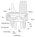
図1〜図3に示すように、ケトル本体Kは、上部が開口し、加熱対象の湯水を貯留する有底筒状の内容器(貯留部の一例)1を内部に有する有底筒状の本体ボディ(容器本体の一例)2と、内容器1内の湯水(水の一例)を加熱する電熱ヒータ(加熱機構の一例)3と、本体ボディ2の概略円形の上方開口部4(内容器1の上部開口にて形成される)を密封状態で閉鎖可能な蓋体5等とを備えて構成されている。
本体ボディ2の底部の外面には、電源プレートSの給電機構Psから出力される電力を受電可能な受電機構Prが設けられている。本体ボディ2の底部には、電熱ヒータ3への通電を許容する通電状態と遮断する通電遮断状態とに切り換え自在なスイッチ機構Bが設けられている。
Hereinafter, an embodiment when the present invention is applied to an electric kettle (an example of a water heating container) will be described with reference to the drawings.
As shown in FIG. 2, the electric kettle includes a power supply plate S and a kettle body K.
The power supply plate S is formed in a substantially disk shape, and a power feeding mechanism Ps is provided at the center of the upper surface thereof.
As shown in FIGS. 1 to 3, the kettle body K has a bottomed cylindrical shape with an open top and an inner container 1 (an example of a storage portion) 1 that stores hot water to be heated. A body body (an example of a container body) 2, an electric heater (an example of a heating mechanism) 3 for heating hot water (an example of water) in the
A power receiving mechanism Pr capable of receiving power output from the power feeding mechanism Ps of the power supply plate S is provided on the outer surface of the bottom of the
ケトル本体Kを電源プレートSに載置すると、給電機構Psと受電機構Prとが電気的に接続されて、後述するスイッチ切換機構Aによりスイッチ機構Bを通電状態に切り換えることで、給電機構Psから受電機構Prを介して電熱ヒータ3等に給電されて、内容器1内の湯水が加熱される構成となっている。以下では、蓋体5の上面を上方側に向けた状態で、ケトル本体Kを電源プレートSに載置した姿勢、ケトル本体Kをテーブル等に載置した姿勢、或いは、ケトル本体Kの軸心が鉛直方向に対して傾斜する傾斜角度が、後述する所定の止水用角度未満の姿勢を正立姿勢とし、当該傾斜角度が、当該所定の止水用角度以上の姿勢を傾斜姿勢として説明する。
When the kettle body K is placed on the power supply plate S, the power feeding mechanism Ps and the power receiving mechanism Pr are electrically connected, and the switch mechanism B, which will be described later, is switched to the energized state by switching the switch mechanism B from the power feeding mechanism Ps. Power is supplied to the
図1〜図3に示すように、蓋体5は、その主要部分が概略円盤状に構成され、周方向における所定の相対位置関係で、本体ボディ2の上方開口部4に着脱自在に構成されて、蓋体5が本体ボディ2の上方開口部4に装着されることにより、上方開口部4が閉鎖される。
蓋体5は、外周部に注ぎ口6を備え、注ぎ口6は、蓋体5における概略円盤状の主要部分の外周部に径方向外方に突出する状態で設けられている。そして、蓋体5が上方開口部4に装着された状態で、上面視で、本体ボディ2及び注ぎ口6の中心部の外周側の位置に設けられるとともに、蓋体5の注ぎ口6を前側とする前後方向において、注ぎ口6とは反対側である後側に対応する本体ボディ2には、ハンドル7が設けられている。ハンドル7は、本体ボディ2の外周部に径方向外方に突出する状態で設けられている。
蓋体5には、蓋体5が本体ボディ2の上方開口部4に装着された状態で、蓋体5を本体ボディ2に保持するための左右一対のフック部材8が設けられている。
As shown in FIGS. 1 to 3, the
The
The
蓋体5には、蓋体5により密封された内容器1と注ぎ口6とを連通し、内容器1内の湯水を注ぎ口6を介して外部に通流させる注出流路9と、注出流路9に設けられ、注出流路9を密封状態で閉鎖可能な弁機構10と、蓋体5により密封された内容器1と注出流路9における弁機構10の下流側とを連通し、内容器1内の湯水から発生する蒸気を注出流路9における弁機構10の下流側に設けられた注ぎ口(蒸気排出口の一例)6に通流させる導出用蒸気流路(蒸気流路の一例)11とが設けられている。
更に、蓋体5には、弁機構10を開閉操作する弁開閉操作部材12と、蓋体5の上方に配置されて、注ぎ口6の上方に当接して当該注ぎ口6の上方を覆う注ぎ口閉状態と注ぎ口6から上方に離間した注ぎ口開状態とに切り換え操作自在な注ぎ口開閉部材13とが設けられている。
The
Further, the
本体ボディ2内の底部には蒸気検知部Cが設けられ、電熱ヒータ3の加熱により内容器1内の湯水が沸騰して発生する蒸気を蒸気検知部Cに導く検知用蒸気流路(蒸気流路の一例)14が、蓋体5と本体ボディ2とにわたって設けられている。なお、本実施形態では、蒸気検知部Cが設定温度(100℃近傍)に加熱されることにより、蒸気を検知するように構成されている。
A steam detection unit C is provided at the bottom of the
ハンドル7は、本体ボディ2の外周部に設けられ、ハンドル7を把持してケトル本体Kを持ち上げて、弁開閉操作部材12により弁機構10を開操作し、鉛直方向Yに対して本体ボディ2の軸心Xを、注ぎ口6側がハンドル7側(蓋体5の中央部)よりも下側となるように傾けることにより、内容器1内の湯水を注ぎ口6から注ぐことができるように構成されている。
The
なお、以下では、上面視で、注ぎ口6とハンドル7とを結ぶ方向を前後方向とし、注ぎ口6側を前側、ハンドル7側を後側として説明し、また、上面視で、本体ボディ2における前後方向に直交する方向を左右方向とし、図3の紙面奥側を右側、紙面手前側を左側として説明し、さらに、縦断側面視で、本体ボディ2における内容器1の底部と蓋体5とを結ぶ方向を上下方向とし、内容器1の底部側を下側、蓋体5側を上側として説明する。
ここで、前後方向には、上面視で、注ぎ口6側とハンドル7側とを結ぶ基準直線に対して、45度未満の角度で交差する直線方向も含む概念であり、左右方向には、前後方向に直交する基準直線に対して、45度未満の角度で交差する直線方向も含む概念であり、上下方向には、縦断側面視で、本体ボディ2における内容器1の底部と蓋体5とを結ぶ基準直線に対して、45度未満の角度で交差する直線方向も含む概念である。
In the following, the direction connecting the
Here, the front-rear direction is a concept including a linear direction intersecting at an angle of less than 45 degrees with respect to a reference straight line connecting the
以下、電気ケトルの各部について、説明する。
先ず、内容器1及び本体ボディ2について、説明する。
図3に示すように、内容器1は、上方側の内容器上部と下方側の内容器下部との間に、それらよりも小径の首部を備えた形状に構成されている。
図1〜図3に示すように、本体ボディ2は、内容器1における内容器上部の上下方向の中間部から下方の部分を全体にわたって覆うように構成されている。つまり、内容器1における内容器上部の上部側の部分が、本体ボディ2から外部に露呈している。
Hereinafter, each part of the electric kettle will be described.
First, the
As shown in FIG. 3, the
As shown in FIGS. 1 to 3, the
次に、図3に示すように、スイッチ切換機構A、スイッチ機構B及び蒸気検知部Cについて、説明する。
公知のシーズヒータからなる電熱ヒータ3、受電機構Prから電熱ヒータ3への通電を断続自在なスイッチ機構B、及び、蒸気検知部Cは、内容器1の底部と本体ボディ2の底部との間の空間に設けられている。
スイッチ機構Bは、電気ケトルにおいて広く用いられていて、周知であるので、図示及び詳細な説明を省略するが、蒸気検知部Cのバイメタル15が設定温度に加熱されて(即ち、蒸気を検知して)変形するのに伴って、オン状態(通電状態)からオフ状態(通電遮断状態)に切り換えられるように構成されている。
Next, as shown in FIG. 3, the switch switching mechanism A, the switch mechanism B, and the steam detector C will be described.
The
Since the switch mechanism B is widely used in an electric kettle and is well known, illustration and detailed description thereof are omitted, but the bimetal 15 of the steam detector C is heated to a set temperature (that is, detects steam). And) is configured to be switched from an on state (energized state) to an off state (energized cut-off state) as it is deformed.
スイッチ切換機構Aは、本体ボディ2のハンドル7の上部に設けられた概略くの字状の押ボタン16と、押ボタン16が押し操作されたときの押ボタン16の動きによりスイッチ機構Bを通電遮断状態から通電状態に切り換え、且つ、スイッチ機構Bが通電状態から通電遮断状態に切り換えられるのに伴って押ボタン16を元の位置に戻すように、押ボタン16とスイッチ機構Bとを連結するリンク機構Dとを備えて構成されている。そして、リンク機構Dが、押ボタン16に連結されるボタン側リンク部17とスイッチ機構Bに連結されるスイッチ側リンク部18とを、互いに枢支連結された状態で備えて構成されている。
The switch switching mechanism A energizes the switch mechanism B by a generally square-shaped
従って、ケトル本体Kを電源プレートSに載置して、押ボタン16のボタン部16aを下方に押すと、押ボタン16の動きに連動して、リンク機構Dの作用により、スイッチ機構Bが通電遮断状態から通電状態に切り換えられる。この状態では、スイッチ機構Bが通電状態に保持される保持力により、押ボタン16のボタン部16aが下降した状態で維持される。これにより、給電機構Psから受電機構Prを介して電熱ヒータ6等に給電されて、内容器1内の湯水が加熱される。
Accordingly, when the kettle body K is placed on the power supply plate S and the
その後、内容器1内の湯水が沸騰して、内容器1内で蒸気が発生すると、その蒸気が、後述する2つの転倒止水弁Gを通過して、導出用蒸気流路11の膨出空間30を介して検知用蒸気流路14を通流し、蒸気検知部Cのバイメタル15が加熱される。そして、バイメタル15が設定温度に加熱されて変形すると、その変形に連動して、スイッチ機構Bが通電状態から通電遮断状態に切り換えられ、リンク機構Dの作用により、押ボタン16がそのボタン部16aが上昇する方向に揺動する。これにより、電熱ヒータ3への通電が遮断されて、内容器1内の湯水の加熱が終了する。
Thereafter, when the hot water in the
次に、蓋体5の主要部について、説明する。
図3に示すように、蓋体5は、本体ボディ2の上方開口部4に着脱自在な蓋本体19と、この蓋本体19に上方から被さる蓋カバー20とを備えて構成されている。蓋本体19及び蓋カバー20夫々の主要部分は、平面視での外形形状が概略円形状になるように構成されている。蓋本体19の外周側下端部には、上方開口部4に装着された蓋本体19と上方開口部4との間を全周に亘って密封状態で閉鎖(シール)する環状シール材19Aが設けられている。
蓋本体19内には、その下面(蓋本体19が本体ボディ2の上方開口部4に装着された状態において、蓋本体19における内容器1内に臨む面)に開口する弁機構10の弁室21が設けられ、更に、蓋本体19には、概略筒状の注ぎ口形成部材22が、基端が弁室21に連通し且つ先端側ほど上位に位置する斜め上向き姿勢で径方向外方に突出する状態で設けられている。
Next, the main part of the
As shown in FIG. 3, the
In the lid
この注ぎ口形成部材22の先端面は、ケトル本体Kが水平な台上に載置された状態で、略水平状となるように、注ぎ口形成部材22の軸心に対して傾斜している。
注ぎ口形成部材22は、先端からの軸心方向視で、下方側に対応する部分が概略V字状に尖った形状に構成されている。
そして、ケトル本体Kが水平な台上に載置された状態で、注ぎ口形成部材22の先端開口部が略垂直方向上方を向くようになり、この注ぎ口形成部材22の先端開口部により、前端側がV字状に尖った形状の注ぎ口6が形成される。なお、弁室21と注ぎ口形成部材22とにより、注出流路9が形成される。
The tip end surface of the
The
And, in a state where the kettle body K is placed on a horizontal table, the tip opening of the
次に、弁機構10及び弁機構10を開閉するための構成について、説明する。
弁機構10は、蓋本体19に設けられ、弁室21と、弁室21における蓋本体19の下面での開口部の縁部にて機能させる弁座23と、上下方向に移動自在で、上方に移動して弁座23に当接した密封状態で湯水の流出を阻止する弁体24と、この弁体24を上方側(即ち、閉状態側)に付勢するスプリング25とを備えて構成されている。
Next, the structure for opening and closing the
The
注ぎ口開閉部材13は、細長状に構成され、注ぎ口開閉部材13が、長手方向を前後方向に沿わせて、長手方向の中間箇所が蓋カバー20の上部に左右方向に沿う注ぎ口開閉軸心A1にて枢支された状態で、蓋体5の上方に配置されている。
そして、注ぎ口開閉部材13における前後方向の後端側の操作部13aを上下方向に移動操作することにより、注ぎ口開閉部材13における前後方向の前端側の蓋部13bが上下方向に揺動して、注ぎ口6の上方に当接して被さる注ぎ口閉状態と注ぎ口6から上方に離間した注ぎ口開状態とに切り換えられるように構成されている。
The spout opening / closing
Then, by operating the
更に、蓋体5の蓋本体19には、注ぎ口開閉部材13の操作部13aが上下方向に移動操作されて、注ぎ口開閉部材13が注ぎ口閉状態と注ぎ口開状態とに切り換え操作されるのに伴って、弁機構10を開閉操作するように注ぎ口開閉部材13と弁機構10とを連結する弁開閉レバー26が設けられている。
弁開閉レバー26は、弁体24の後方側において、前後方向の中間部が左右方向に沿う弁開閉軸心A2にて枢支された状態で設けられている。
弁開閉レバー26の前端部の作用部26aが、弁体24の上方に位置し、後端部の係止部26bが、注ぎ口開閉部材13における注ぎ口開閉軸心A1での枢支箇所よりも前方側の箇所から下方に突出する引っ掛け部13cにより持ち上げ可能に配置されている。
Further, on the
The valve opening / closing
The
そして、注ぎ口開閉部材13の操作部13aを下方に押すのに伴って、注ぎ口開閉部材13の引っ掛け部13cによって弁開閉レバー26の係止部26bが上方に持ち上げられると共に、作用部26aが下方に移動され、作用部26aにより弁体24がスプリング25の付勢力に抗して下方に押し下げられて、弁機構10が開弁されるように構成されている。又、注ぎ口開閉部材13の操作部13aを下方に押す力を開放すると、スプリング25の付勢力により弁体24が上昇して弁機構10が閉弁されると共に、注ぎ口開閉部材13の操作部13aが上方に戻るように構成されている。
Then, as the operating
次に、導出用蒸気流路11及び検知用蒸気流路14について、説明する。
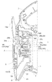
図3及び図4に示すように、導出用蒸気流路11は、蓋体5により密封された内容器1と注出流路9における弁機構10の下流側に位置する注ぎ口6とを連通し、内容器1内の湯水から発生する蒸気を注出流路9における弁機構10の下流側に位置する注ぎ口6に通流させるように構成されている。具体的には、導出用蒸気流路11は、蓋体5内において、内容器1側から、転倒止水弁Gの蒸気流入孔(上流側蒸気孔の一例)28、収容室36、蒸気導入口(下流側蒸気孔の一例)29、膨出空間30、導出口31、貫通孔19Bを経て、注出流路9の弁機構10の下流側である弁室21、注ぎ口6に連通するように構成されている。
検知用蒸気流路14は、蒸気導入口29を介して膨出空間30内に流入した蒸気の一部を、検知側蒸気導入口2hを介して蒸気検知部Cに通流させるように構成され、蓋体5と本体ボディ2に亘って設けられている。
Next, the
As shown in FIGS. 3 and 4, the
The detection
先ず、導出用蒸気流路11について、説明する。
図3及び図4に示すように、導出用蒸気流路11に設けられる転倒止水弁Gの錘体収納用窪み部27は、蓋本体19の上面から下方側に窪み形成されるとともに、左右方向に並列する状態で一対設けられており、左側に第1錘体収納用窪み部27a、右側に第2錘体収納用窪み部27bが配設されている。なお、左右方向における第1錘体収納用窪み部27aと第2錘体収納用窪み部27bとの間には、両錘体収納用窪み部27a、27bを区画する区画壁27cが設けられている(図4参照)。又、両錘体収納用窪み部27a、27bの上方がシール部材33を介して下側壁部材34で覆われ、更に、下側壁部材34の上方が上側壁部材35にて覆われている。なお、詳細は後述するが、下側壁部材34と上側壁部材35とにより蒸気流路形成部材Eが形成されている。
First, the
As shown in FIGS. 3 and 4, the
第1錘体収納用窪み部27aの第1底壁部(第1収容室の底壁部の一例)27dは、前後方向において本体ボディ2の軸心Xに対して略直交するように形成され、この第1底壁部27dの外周縁部の下端には、内容器1から蒸気が流入する複数の第1蒸気流入孔(蒸気流入孔、上流側蒸気孔の一例)28aが貫通形成されている(図4参照)。
第2錘体収納用窪み部27bの第2底壁部(第2収容室の底壁部の一例)27eは、前後方向において前側から後側(注ぎ口6側からハンドル7側)に向かうにつれて下方側に傾斜するように形成され、この第2底壁部27eのハンドル7側の下端(底壁部27eにおいて最も下方側に位置する箇所)には、内容器1から蒸気が流入する第2蒸気流入孔(蒸気流入孔、上流側蒸気孔の一例)28bが貫通形成されている。
そして、第2蒸気流入孔28bの開口面積は、第1蒸気流入孔28aの総開口面積よりも小さく設定されている。
A first bottom wall portion (an example of a bottom wall portion of the first storage chamber) 27d of the first
The second bottom wall portion (an example of the bottom wall portion of the second storage chamber) 27e of the second
The opening area of the second
又、下側壁部材34は、第1錘体収納用窪み部27aの上方を覆う第1天井壁部34d及び第2錘体収納用窪み部27bの上方を覆う第2天井壁部34eを備え、第1天井壁部34dには、第1錘体収納用窪み部27aに対して開口する第1蒸気導入口(蒸気導入口、下流側蒸気孔の一例)29Aが形成され、第2天井壁部34eには、第2錘体収納用窪み部27bに対して開口する第2蒸気導入口(蒸気導入口、下流側蒸気孔の一例)29Bが形成されている。
そして、第2蒸気導入口29Bの開口面積は、第1蒸気導入口29Aの開口面積よりも小さく設定されている。
The
The opening area of the
第1錘体収納用窪み部27a及び第2錘体収納用窪み部27bとそれらの上方を覆う下側壁部材34により、第1蒸気流入孔28a及び第1蒸気導入口29Aを有する概略箱状の第1収容室(収容室の一例)36Aと、第2蒸気流入孔28b及び第2蒸気導入口29Bを有する概略箱状の第2収容室36Bとが形成され、第1収容室36Aには球体からなる第1錘体(錘体、止水部材の一例)37aが収納され、第2収容室36Bには球体からなる第2錘体(錘体、止水部材の一例)37bが収納されている。球体とすることにより、本体ボディ2の傾斜角度に応じて各錘体37a、37bが後述する誘導壁に沿って迅速に移動することとなり、導出用蒸気流路11の閉鎖を迅速に行うことができるとともに、重量の軽量化を図ることができる
The first
図3、図5及び図6に示すように、下側壁部材34の下面には、当該下面から下方側(底壁部側)に突出する複数の板状突出部34Aが形成されており、複数の板状突出部34Aは、第1蒸気導入口29Aを中心として当該第1蒸気導入口29Aの外周側を環状に囲繞するように配列(本実施形態では、周方向で等間隔に6本配列)されるとともに、第2蒸気導入口29Bを中心として当該第2蒸気導入口29Bの外周側を環状に囲繞するように放射状に配列(本実施形態では、周方向で等間隔に6本配列)されている。
そして、下側壁部材34を第1錘体収納用窪み部27a及び第2錘体収納用窪み部27bの上方を覆うように配置すると、本実施形態では、環状に配列された6本の板状突出部34Aが第1錘体収納用窪み部27a内に位置するとともに、環状に配列された6本の板状突出部34Aが第2錘体収納用窪み部27b内に位置するように構成されている。
As shown in FIGS. 3, 5, and 6, the lower surface of the
Then, when the
図5及び図6に示すように、各板状突出部34Aは、一対の平板面(図示せず)が第1蒸気導入口29A又は第2蒸気導入口29Bの径方向に対して略平行となるように放射状に配置され、各板状突出部34Aには、一対の平板面の厚みにより形成される面のうち第1蒸気導入口29A又は第2蒸気導入口29Bに対して径方向で対向する径方向内側面(誘導壁の一例)34fが形成されている。
この径方向内側面34fは、下側壁部材34の第1天井壁部34dの下面又は第2天井壁部34eの下面から下方側に向かって直線状に延出するように形成されている。
As shown in FIGS. 5 and 6, each plate-
The radially
複数の板状突出部34Aのうち第2天井壁部34eの下面から下方側に突出する複数の板状突出部34Aには、注ぎ口6側に位置(第2蒸気導入口29Bの中心よりも前側に位置)する複数の特定板状突出部34Bを備えている。本実施形態では、複数の特定板状突出部34Bは、第2蒸気導入口29Bの周囲に3本配置されている。
又、複数の特定板状突出部34Bは、複数の特定板状突出部34Bのうち注ぎ口6側に最も近接する位置の注ぎ口側特定板状突出部34Cと、当該注ぎ口側特定板状突出部34Cに隣接する隣接特定板状突出部34Dとを備えている。本実施形態では、注ぎ口側特定板状突出部34Cは、第2蒸気導入口29Bの周囲に1本配置され、複数の隣接特定板状突出部34Dは、第2蒸気導入口29Bの周囲に2本配置されている。また、注ぎ口側特定板状突出部34Cは、上面視で、前後方向に沿って前側である注ぎ口6側に対応する箇所に位置している。
Among the plurality of plate-
Further, the plurality of specific plate-like projecting
特定板状突出部34Bには、注ぎ口6側に位置(第2蒸気導入口29Bの中心よりも前側に位置)する、径方向内側面34fとしての特定径方向内側面(特定誘導壁の一例)34gが形成されている。特定板状突出部34Bのうち注ぎ口側特定板状突出部34Cには、注ぎ口6側に最も近接する位置に位置する、特定径方向内側面34gとしての注ぎ口側特定径方向内側面(注ぎ口側特定誘導壁の一例)34hが形成されており、隣接特定板状突出部34Dには、当該注ぎ口側特定径方向内側面34hに隣接する一対の隣接特定径方向内側面(隣接特定誘導壁の一例)34iとが形成されている。本実施形態では、注ぎ口側特定径方向内側面34hは、第2蒸気導入口29Bの周囲に1箇所配置され、複数の隣接特定径方向内側面34iは、第2蒸気導入口29Bの周囲に2箇所配置されている。
The specific plate-like projecting
従って、下側壁部材34を第1錘体収納用窪み部27a及び第2錘体収納用窪み部27bの上方を覆うように配置すると、第1収容室36A内に位置する複数の板状突出部34Aの径方向内側面(第1誘導壁の一例)34fが、球体からなる第1錘体37aの外周面を第1収容室36Aの第1天井部34d及び第1底壁部27d以外の側方箇所から囲繞するように配置されるとともに、第2収容室36B内に位置する複数の板状突出部34Aの径方向内側面(第2誘導壁の一例)34fが、球状の第2錘体37bの外周面を第2収容室36Bの第2天井部34e及び第2底壁部27e以外の側方箇所から囲繞するように配置される。
Therefore, when the
これにより、転倒止水弁Gの錘体37(第1錘体37a及び第2錘体37b)が、鉛直方向Yに対する本体ボディ2の軸心Xの傾斜角度に応じて板状突出部34Aの径方向内側面34fに沿って収容室36の底壁部(第1底壁部27d、第2底壁部27e)と天井壁部(第1天井壁部34d、第2天井壁部34e)との間を移動することにより、導出用蒸気流路11の蒸気導入口29(第1蒸気導入口29A及び第2蒸気導入口29B)を閉鎖する止水状態と導出用蒸気流路11の蒸気導入口29を開放する止水解除状態とに切換え可能に構成されている。そして、この切換えにおいて、錘体37(第1錘体37a及び第2錘体37b)を板状突出部34Aの径方向内側面34fに沿って案内した状態で移動させる際、本体ボディ2の傾斜に伴う錘体37(第1錘体37a及び第2錘体37b)の傾斜による自重を、複数の径方向内側面34fにより錘体37(第1錘体37a及び第2錘体37b)の全周に亘る側方箇所から支持しつつ案内することができ、より的確且つ確実な移動を実現することができる
そして、鉛直方向Yに対して本体ボディ2の軸心Xが所定の止水用角度未満傾斜した正立姿勢では、各錘体37a、37bが各錘体収納室36A、36Bの底面で受けられて、各錘体収納室36A、36Bの天井面(即ち、下側壁部材34の下面)から離間した状態となり、各蒸気流入孔28a、28b及び各蒸気導入口29A、29Bが開放されて、内容器1からの蒸気が各錘体収納室36A、36B内を通過可能(止水解除状態)となる。
一方で、鉛直方向Yに対して本体ボディ2の軸心Xが所定の止水用角度以上傾斜した傾斜姿勢では、各錘体37a、37bが板状突出部34Aの径方向内側面34fに沿って移動して各錘体収納室36A、36Bの天井壁部(第1天井壁部34dの下面、第2天井壁部34eの下面)で受けられて、各錘体37a、37bにより各蒸気導入口29A、29Bが塞がれ、各錘体収納室36A、36Bを通しての湯水の通過が阻止(止水状態)されて、内容器1内の湯水の注ぎ口6からの漏出が防止される。
ちなみに、転倒止水弁Gは、第1収容室36Aと、第1蒸気流入孔28aと、第1蒸気導入口29Aと、第1収容室36A内に位置する複数の板状突出部34Aの径方向内側面34fと、第1錘体37aとを備えた第1転倒止水弁G1、及び、第2収容室36Bと、第2蒸気流入孔28bと、第2蒸気導入口29Bと、第2収容室36B内に位置する複数の板状突出部34Aの径方向内側面34fと、第2錘体37bとを備えた第2転倒止水弁G2を備えている。
As a result, the weight body 37 (the
On the other hand, in the inclined posture in which the axis X of the
Incidentally, the tip-off water stop valve G has a diameter of the
第2天井部34eの下面から下方側に突出し且つ第2収容室36B内に収容される板状突出部34Aの径方向内側面34fのうち、注ぎ口6側に位置する特定板状突出部34Bの特定径方向内側面34gには、縦断面視で、径方向における第2蒸気導入口29Bの開口端からの距離が、第2天井壁部34e側の箇所よりも第2収容室36Bの底壁部27e側の箇所の方が大きくなるように構成された段部(邪魔部の一例)34xが形成されている。
なお、複数の径方向内側面34fのうち特定板状突出部34Bの特定径方向内側面34g以外の径方向内側面34fには、当該段部34xは形成されておらず、例えば、径方向内側面34fは、縦断面視で、径方向における第2蒸気導入口29Bの開口端からの距離が、第2天井壁部34e側の箇所及び第2収容室36Bの底壁部27e側の箇所で略同一の距離となるように構成されている。
The specific plate-like projecting
Note that the stepped
特定板状突出部34Bの特定径方向内側面34gに形成された段部34xのうち、注ぎ口6側に最も近接する位置の注ぎ口側特定径方向内側面34hに形成された注ぎ口側段部34yが、当該注ぎ口側特定径方向内側面34hに隣接する一対の隣接特定径方向内側面34iに形成された隣接段部34zよりも大きな段差を備えるように構成されている。即ち、縦断面視で、第2蒸気導入口29Bの径方向において、注ぎ口側段部34yの段差よりも隣接段部34zの段差の方が小さくなるように構成されている。
又、注ぎ口側段部34y及び隣接段部34zは、本体ボディ2の軸心X方向(上下方向)において特定径方向内側面34gの中央部に形成されるとともに、本体ボディ2がテーブル等に載置された正立姿勢では、球体からなる第2錘体37bが第2収容室36Bの第2底壁部27eの上面に当接した状態で、当該第2錘体37bの中心よりも上方側(第2天井壁部34e側)に位置するように形成されている。
Out of the
The
これにより、段部34xが、第2転倒止水弁における特定板状突出部34Bの特定径方向内側面34gに形成されているので、注ぎ口6が下側に位置する状態で鉛直方向Yに対する本体ボディ2の軸心Xの傾斜角度が、所定の止水用角度以上且つ所定の邪魔用角度以下の邪魔用角度範囲内にあるときに、第2錘体37bが止水解除状態から止水状態となるのを阻止するように構成されている。なお、段部34xは、鉛直方向Yに対する本体ボディ2の軸心Xの傾斜角度が、所定の止水用角度以上且つ所定の邪魔用角度以下の邪魔用角度範囲内にあるときに、第2錘体37bを止水解除状態に維持することができ、所定の邪魔用角度を超えた傾斜角度(邪魔用角度範囲外)となったときに、第2錘体37bを止水状態に切換えることができる段差となるように形成されている。
つまり、導出用蒸気流路11の注ぎ口6側には、第2錘体37bが止水解除状態から止水状態となるのを阻止する段部34xが設けられていることとなり、本体ボディ2の軸心Xを注ぎ口6側が下側に位置するように傾斜させた場合において、傾斜角度が所定の止水用角度以上且つ所定の邪魔用角度以下の邪魔用角度範囲内にあるときに、段部34xが、第2錘体37bが止水解除状態から止水状態となるのを阻止するように構成されていることとなる。なお、導出用蒸気流路11の注ぎ口6側とは、導出用蒸気流路11内において、上面視で、注ぎ口6とハンドル7とを結ぶ直線である前後方向の基準直線(注ぎ口6の中央)に対して、左右方向に±30度程度交差(傾斜)した角度範囲内の箇所をいう。
Thereby, since the
That is, on the
図3、図5及び図6に示すように、導出用蒸気流路11の膨出空間30は、蒸気流路形成部材Eとしての下側壁部材34とその上方を覆う上側壁部材35とを組み付けることにより、当該蒸気流路形成部材Eの内部に形成される。
この膨出空間30は、上流側である各蒸気導入口29A、29Bから導入された蒸気の一部を、下流側である下側壁部材34の導出口31及び蓋本体19の貫通孔19Bを介して注出流路9の弁室21に通流可能に形成されるとともに、当該蒸気の他部を、当該膨出空間30に連通する検知用蒸気流路14に通流可能に形成されている。
なお、上面視で、蓋本体19においてハンドル7側に位置し且つ弁座23の上部に対応する箇所には、当該蓋本体19を上下方向に貫通する貫通孔19Bが形成され、貫通孔19Bの上部周縁部には上方に突出するリブ(図示せず)が形成されている。当該リブが下側壁部材34の導出口31に内嵌された状態で、貫通孔19Bが導出口31に連通するように構成されており、当該貫通孔19Bが導出用蒸気流路11の下流側端部に形成された蒸気導出口32として機能する。
As shown in FIGS. 3, 5, and 6, the bulging
The bulging
In a top view, a through
蒸気流路形成部材Eは、平面視での外形が略相似形状で左右方向に長い板状部材である下側壁部材34及び上側壁部材35を備えて構成されており、下側壁部材34及び上側壁部材35は、注ぎ口6とハンドル7との間で且つ蓋本体19における転倒止水弁G及び貫通孔19Bの上部に位置するように、複数のビス(図示せず)により装着固定される。なお、この装着固定は、下側壁部材34及び上側壁部材35において左右方向の両側及び前後方向の前側に形成された取付けフランジ部(図示せず)にビスを挿通し、当該ビスを蓋本体19に設けられたネジ孔(図示せず)に螺合させる形態で行われる。
The steam flow path forming member E includes a lower
下側壁部材34の上面側と上側壁部材35の下面側とを当接させて組み付けると、下側壁部材34と上側壁部材35とにより、平面視で、前後方向の後側(ハンドル7側)に延出する筒状部38が形成される。この筒状部38の後側(ハンドル7側)には、ハンドル7側に向かって開口する開口部38Aが形成され、検知用蒸気流路14と連通するように構成されている。この筒状部38には、シリコーンゴムにより構成されたパッキン部材39が外嵌装着され、内容器1においてハンドル7の前側に貫通形成された検知側蒸気導入口2hの周縁部を密封することができるように構成されている(図3参照)。
When the upper wall side of the
下側壁部材34は、左右方向に長い板状部材であり、第1蒸気導入口29A及び第2蒸気導入口29Bが左右方向に沿って並列するように配置されている。下側壁部材34の上面の外周部において後側に位置する開口部34c以外の全周に亘って、当該上面から上方に突出する突出外壁34a及び突出内壁34bが形成されている。突出外壁34a及び突出内壁34bの内側には、第1蒸気導入口29A及び第2蒸気導入口29Bの両方を、後側(開口部34c)以外の3方向(前側、左右側)で囲繞する空間が形成される。なお、開口部34cは、下側壁部材34において左右方向の中央部に位置するように開口形成されている。
下側壁部材34の突出外壁34aと突出内壁34bとの間には、厚み方向の中央部に、後述する上側壁部材35の突出外壁35a及び突出内壁35bの嵌合凸部(図示せず)を嵌合できる嵌合溝(図示せず)が形成されている。
下側壁部材34内において、左右方向の中央部で且つ注ぎ口6側(前側)の端部位置には、上面から下方側に貫通する導出口31が形成され、蓋本体19の貫通孔19Bと連通するように構成されている。
The lower
Between the projecting
In the
また、下側壁部材34の下面には、蓋本体19の上部に装着された状態で、転倒止水弁Gにおける両収容室36A、36Bの外周縁部に形成された位置決め用リブ(図示せず)を嵌合可能な環状溝(図示せず)が窪み形成されており、下側壁部材34を蓋本体19の上部に装着する際に、環状溝を位置決め用リブに嵌合させることで容易に位置決めできるように構成されている。また、位置決め用リブの外周側にはシール材33が設けられており、転倒止水弁Gの外周縁部と下側壁部材34の下面との間は密封される。
Further, positioning ribs (not shown) formed on the outer peripheral edge portions of the
上側壁部材35は、左右方向に長い板状部材であり、上側壁部材35の板状部材の下面側の外周部において後側に位置する開口部35c以外の全周に亘って、当該下面から下方に突出する突出外壁35a及び突出内壁35bが形成されている。従って、突出外壁35a及び突出内壁35bの内側には、後側(開口部35c)以外の3方向(前側、左右側)で囲繞する空間が形成される。なお、開口部35cは、上側壁部材35において左右方向の中央部に位置するように開口形成されている。
上側壁部材35の突出外壁35aと突出内壁35bとの間には、厚み方向の中央部に、下側壁部材34の突出外壁34a及び突出内壁34bの嵌合溝(図示せず)に嵌合できる嵌合凸部(図示せず)が形成されている。
The upper
Between the protruding
下側壁部材34と上側壁部材35とが嵌合した箇所においては、下側壁部材34と上側壁部材35とが密封された状態となっている。又、下側壁部材34の開口部34cと上側壁部材35の開口部35cとが合わさることで開口部38Aが形成されている。開口部38Aを形成する筒状部38には、開口部38Aを密封するようにパッキン部材39が装着される。そして、このように組み付けられた蒸気流路形成部材Eを蓋体5の蓋本体19の上面に装着し、当該蓋体5を本体ボディ2の上方開口部4に取り付けると、蒸気流路形成部材Eの内部に、上述の膨出空間30が形成される。
At the place where the
次に、検知用蒸気流路14について、説明する。
図3に示すように、検知用蒸気流路14は、検知側蒸気導入口2hと内容器1の底部に設けられた蒸気検知部Cとにわたって延びるように、内容器1の外部に設けられている。
検知用蒸気導入口2hは、内容器1の内容器上部において、前側の部分よりも高く形成され且つ膨出空間30の後側に隣接する状態にまで立ち上がるように形成された後側の部分に形成され、膨出空間30に連通接続されている。
Next, the
As shown in FIG. 3, the
The
具体的には、長手方向に直交する方向での横断面形状が概略コの字状の細長状の検知用蒸気流路形成体46が、後側から検知側蒸気導入口2hを覆うとともに、蒸気検知部Cに連通する状態で、開口部を内容器1の外面の後側の部分に上下方向に沿わせて当て付けて設けられ、内容器1の外面と検知用蒸気流路形成体46との間に、検知用蒸気流路14が形成される。尚、検知用蒸気流路形成体46は、横断面形状が概略コの字状となると共に、長手方向が内容器1の外面に上下方向に沿う形状となるように、樹脂成型により形成されて、内容器1の外面に密着させて設けることが可能なように構成されている。
Specifically, an elongated detection steam
次に、上記のように構成された電気ケトルを用いて、内容器1内の湯水を加熱し、加熱された湯水を注ぎ口6から注出する際の状態について、説明する。
Next, the state at the time of heating the hot water in the
使用者が、本体ボディ2を電源プレートS上に載置し、内容器1内の湯水を加熱するために押ボタン16のボタン部16aを押圧すると、給電機構Psから受電機構Prを介して電熱ヒータ3に電力が供給され、電熱ヒータ3により内容器1内の湯水が加熱される。
当該加熱に伴って内容器1内の湯水から蒸気が発生すると、当該蒸気は順次上昇して転倒止水弁Gの蒸気流入孔28、収容室37、蒸気導入口29を介して膨出空間30内に導入されることとなる。そして、膨出空間30内に導入された蒸気の一部は、蒸気流路形成部材Eの筒状部38、開口部38A及び検知側蒸気導入口2hを介して検知用蒸気流路14に流入し、蒸気検知部Cに導かれ、当該蒸気の他部は、膨出空間30から導出口31及び貫通孔19Bを介して注出流路9において弁機構10の下流側に導かれ、結露していない蒸気が注ぎ口6から排出される。
When the user places the
When steam is generated from the hot water in the
その後、内容器1内の湯水の加熱が終了して(場合によっては、加熱途中でもよい)、加熱された湯水を注ぎ口6を介して外部に注出する際には、使用者はハンドル7を把持しながら注ぎ口開閉部材13の操作部13aを操作し、本体ボディ2を注ぎ口6側がハンドル7側よりも下方となるように傾けることにより、内容器1内の湯水を注ぎ口6から外部に通流させることができる。
Thereafter, when the heating of the hot water in the
ここで、上述のように構成された電気ケトルでは、図7及び図8に示すように、加熱された湯水を注ぎ口6を介して外部に注出する際に、使用者が、注ぎ口開閉部材13の操作部13aを操作せずに、本体ボディ2を注ぎ口6側がハンドル7側よりも下方に位置するように傾けた傾斜姿勢のまま維持した場合でも、下記に説明するように、内容器1の内圧が上昇することはない。
Here, in the electric kettle configured as described above, when the heated hot water is poured out through the
具体的には、図7及び図8に示すように、使用者がハンドル7を把持し、内容器1内の湯水を注ぎ口6を介して外部に注出しようとして、弁機構Vの弁体24を開操作しない状態で、注ぎ口6が下側に位置するように本体ボディ2の軸心Xを鉛直方向に対して傾斜させた傾斜姿勢とし、その傾斜角度が所定の止水用角度以上邪魔用角度以下の邪魔用角度範囲内にある場合には、図8に示すように、第1転倒止水弁の第1錘体37aが板状突出部34Aの径方向内側面34fに沿って移動して、比較的開口面積の大きな第1蒸気導入口孔29A(図4参照)を閉鎖する(止水状態とする)のに対して、第2転倒止水弁の第2錘体37bは特定板状突出部34Bの特定径方向内側面34gに沿って移動するものの、当該特定径方向内側面34gに設けられた段部34xに引っ掛かることにより当該移動が阻止されて、止水解除状態から止水状態となるのが阻止され、第2錘体37bは止水解除状態のまま維持され、比較的開口面積の小さな第2蒸気導入口29Bを閉鎖しない(止水解除状態とする)ように構成されている。本実施形態では、鉛直方向Yに対する本体ボディ2の軸心Xの傾斜角度を90度とし、所定の止水用角度を90度に設定し、所定の邪魔用角度を110度に設定して、邪魔用角度範囲を90度以上110度以下に設定しているため、図7及び図8では、本体ボディ2の傾斜角度は所定の止水用角度(邪魔用角度範囲内)となっている。
つまり、注ぎ口6が下側に位置するように本体ボディ2を傾斜姿勢とした際において、その傾斜角度が邪魔用角度範囲内にある場合には、第1蒸気導入口孔29Aを閉鎖することで、内容器1内の湯水が開口面積の大きな第1蒸気導入口孔29Aから導出用蒸気流路11及び注出流路9の注ぎ口6を介して外部に漏出することを防止しながら、第2蒸気導入口29Bを開放することで、内容器1内の蒸気を開口面積の小さな第2蒸気導入口29Bから導出用蒸気流路11及び注出流路9の注ぎ口6を介して外部に排出させることができる。
Specifically, as shown in FIGS. 7 and 8, the user grasps the
That is, when the
この際には、複数の特定径方向内側面34fのうち注ぎ口側に最も近接する位置の注ぎ口側特定径方向内側面34hに設けられた注ぎ口側段部34yが、注ぎ口側特定径方向内側面34hに隣接する隣接特定径方向内側面34iに形成された隣接段部34zよりも大きな段差を備えるように構成されているので、注ぎ口6が下側に位置するように本体ボディ2の軸心Xを鉛直方向Yに対して傾斜させた傾斜姿勢とし、その傾斜角度が邪魔用角度範囲内であれば、第2錘体37bは、大きな段差を備えた注ぎ口側段部34yに確実に引っ掛かることにより特定径方向内側面34fに沿う移動が確実に阻止されるとともに、小さな段差を備えた隣接段部34zに引っ掛かることによっても特定径方向内側面34yに沿う移動が阻止されて、止水解除状態から止水状態となるのが阻止される。
At this time, the spout side
又、第2蒸気流入孔28bが、注ぎ口6側とは反対側であって、第2収容室36Bの第2底壁部27eの下端に設けられているので、注ぎ口6が下側に位置するように本体ボディ2の軸心Xを鉛直方向Yに対して傾斜させた傾斜姿勢とした際、傾斜角度が邪魔用角度範囲にある場合に、第2蒸気流入孔28bは注ぎ口6よりも上方側に位置することとなり、第2蒸気流入孔28bをできるだけ水没しないように構成して、内容器1と第2収容室36Bの第2蒸気流入孔28b及び第2蒸気導入口29Bを介する導出用蒸気流路11(注ぎ口6)との連通をできるだけ維持することができる。
Further, since the second
従って、第1転倒止水弁G1により導出用蒸気流路11から内容器1内の湯水が漏出することを防止しながら、第2転倒止水弁G2により内容器1内の内圧の上昇及び湯水が注ぎ口6から勢いよく突出することを防止できる。
Therefore, while preventing the hot water in the
又、このように、注ぎ口6側が下側に位置するように本体ボディ2の軸心Xを鉛直方向Yに対して傾斜させた傾斜姿勢とした際、図9及び図10に示すように、その傾斜角度が所定の邪魔用角度を超えれば(邪魔用角度範囲外となれば)、第1錘体37aは止水状態を維持して導出用蒸気流路11を閉鎖できることに加えて、第2錘体37bは段部34xを乗り越えて止水解除状態から止水状態となり、導出用蒸気流路11を閉鎖することができる。なお、図9及び図10では、鉛直方向Yに対する本体ボディ2の軸心Xの傾斜角度は、110度を超えた状態を示している。
よって、導出用蒸気流路11に転倒止水弁Gを設けた場合において、転倒止水弁Gの基本的な機能を維持しながら、本体ボディ2を傾斜させて注ぎ口6から湯水を注出する際に、内容器1の内圧の上昇を防止でき、湯水が注ぎ口6から勢いよく突出することを防止できる。
Also, when the tilted posture is such that the axis X of the
Therefore, when the tip-off water stop valve G is provided in the
一方で、段部34xが、第2天井壁部34eの下面から下方側に突出する板状突出部34Aの径方向内側面34fのうち注ぎ口6側に位置する特定径方向内側面34gに設けられているので(注ぎ口6側に位置しない径方向内側面34fには、段部34xは設けられていないので)、本体ボディ2が転倒等して、注ぎ口6が下側に位置しない状態で本体ボディ2の軸心Xが鉛直方向Yに対して傾斜した傾斜姿勢となった際には、その傾斜角度が止水用角度以上(所定の止水用角度以上且つ所定の邪魔用角度以下の邪魔用角度範囲内を含む)であれば、錘体37(第1錘体37a及び第2錘体37b)は段部34xの存在しない径方向内側面34fに沿って止水解除状態から止水状態となって、導出用蒸気流路11を閉鎖することができる。
On the other hand, the
他方で、傾斜角度が邪魔用角度範囲内であるが、注ぎ口6が下側に位置しない状態で傾斜姿勢となった場合(本体ボディ2が転倒した場合等)には、使用者が注ぎ口6を介して内容器1内の湯水を注出しようとしていない可能性が高いため、第2錘体37bを早期に止水解除状態から止水状態に切換える必要がある。ここで、注ぎ口6が下側に位置しない状態で傾斜姿勢となった場合には、第2錘体37bが、注ぎ口側特定板状突出部34Cの注ぎ口側特定径方向内側面34hの注ぎ口側段部34yには引っ掛からない状態で、隣接特定板状突出部34Dの隣接特定径方向内側面34iと板状突出部34Aの径方向内側面34fとに亘って当接することがあるが、この状態では、当該第2錘体37bが、隣接特定径方向内側面34iの隣接段部34zに引っ掛かり、止水解除状態から止水状態となるのが阻止されてしまう場合がある。
このような場合でも、隣接段部34zは比較的小さな段差により構成されているので、隣接段部34zに引っ掛かった第2錘体37bは、隣接段部34を早期に乗り越えて、できるだけ早期に止水状態に切換えることができ、早期に導出用蒸気流路11を閉鎖することができる。
On the other hand, when the tilt angle is within the range for the baffle but the pouring
Even in such a case, the adjacent stepped
〔別実施形態〕
(A)上記実施形態では、誘導壁を下側壁部材34の下面から下方側に突出する複数の板状突出部34Aの径方向内側面34fにより構成したが、誘導壁の構成は適宜変更することができる。
例えば、鉛直方向Yに対する本体ボディ2の軸心Xの傾斜角度に応じて、錘体37(止水部材の一例)を適切に止水状態と止水解除状態とに案内することができれば、誘導壁を、収容室36を構成する側方壁により構成することもでき、又、誘導壁を、収容室36内に配置した板状・壁状の部材により構成することもできる。
[Another embodiment]
(A) In the above embodiment, the guide wall is configured by the radially
For example, if the weight body 37 (an example of a water stop member) can be appropriately guided to a water stop state and a water stop release state according to the inclination angle of the axis X of the
(B)上記実施形態では、邪魔部を下側壁部材34の下面から下方側に突出する複数の板状突出部34Aのうち注ぎ口6側に位置する特定板状突出部34Bの特定径方向内側面34gの段部34xにより構成したが、導出用蒸気流路11の注ぎ口6側に位置して、錘体37が止水解除状態から止水状態となるのを阻止することができる構成であれば、その他の構成を採用することができ、例えば、当該特定板状突出部34Bに錘体37との摩擦を増大させる摩擦保持部を設ける構成としてもよい。
この摩擦保持部としては、当該特定径方向内側面34gの表面の一部の摩擦係数が増大するように微細な凹凸を形成する(表面を粗くする)表面加工をした構成とすることができる。
具体的には、上下方向において、特定径方向内側面34gの表面における下端から上端までの全面に亘って微細な凹凸を形成したり、下端から上端に至る途中までの領域に微細な凹凸を形成したり、下端と上端との途中から上端に至るまでの領域に微細な凹凸を形成したり、下端と上端との途中の箇所に微細な凹凸を形成したりする等により、摩擦保持部を形成することができる。
又、この摩擦保持部としては、特定板状突出部34Bの一部に摩擦係数の高いゴム製品等を装着した構成等を例示することができる。
具体的には、上下方向において、特定板状突出部34Bの下端部や下端と上端との間の中間部分に、摩擦抵抗の高いゴム製品等を装着する等により、摩擦保持部を形成することができる。
又、誘導壁を、収容室36を構成する側方壁により構成した場合には、邪魔部を当該側方壁に設けるように構成することもできる。
更に、邪魔部を誘導壁に設けずに、誘導壁を構成する部材以外の部材に邪魔部を設ける構成としてもよい。
例えば、邪魔部を、収容室36の壁面から突出するリブ状の板部材により構成し、当該板部材を誘導壁としての複数の特定板状突出部34Bの隣接間から突出配置するように構成してもよい。
(B) In the above-described embodiment, the specific plate-like projecting
The friction holding portion may have a surface processing that forms fine irregularities (roughens the surface) so as to increase the friction coefficient of a part of the surface of the specific radial
Specifically, in the vertical direction, fine irregularities are formed over the entire surface from the lower end to the upper end of the surface of the specific radial
Moreover, as this friction holding | maintenance part, the structure etc. which mounted | worn with the rubber product etc. with a high friction coefficient in a part of specific plate-shaped
Specifically, in the vertical direction, the friction holding portion is formed by attaching a rubber product or the like having a high frictional resistance to the lower end portion of the specific plate-like projecting
Further, when the guide wall is constituted by a side wall constituting the
Furthermore, it is good also as a structure which provides a baffle part in members other than the member which comprises a guide wall, without providing a baffle part in a guide wall.
For example, the baffle portion is constituted by a rib-like plate member protruding from the wall surface of the
(C)上記実施形態では、邪魔部を下側壁部材34の下面から下方側に突出する複数の板状突出部34Aのうち注ぎ口6側に位置する特定板状突出部34Bの特定径方向内側面34gの段部34xにより構成し、本体ボディ2の軸心Xを注ぎ口6側が下側に位置するように傾斜させた場合において、傾斜角度が所定の止水用角度以上且つ所定の邪魔用角度以下の邪魔用角度範囲内にあるときに、邪魔部が、第2錘体37bが止水解除状態から止水状態となるのを阻止するように構成したが、例えば、当該傾斜角度に関係なく、本体ボディ2の軸心Xが注ぎ口6側が下側に位置するように傾斜させた場合に、邪魔部が、錘体37を常に止水解除状態に維持させて、止水状態とはならないように常に阻止する構成とすることもできる。
(C) In the above-described embodiment, the specific plate-shaped protruding
(D)上記実施形態では、鉛直方向Yに対する本体ボディ2の軸心Xの傾斜角度を90度とし、所定の止水用角度を90度に設定し、所定の邪魔用角度を110度に設定して、邪魔用角度範囲を90度以上110度以下に設定した例について説明したが、所定の止水用角度は、容器本体4の軸心Xが水平方向と略平行(当該軸芯Xの傾斜角度が90度程度)となった転倒姿勢の際に、第1錘体37aが第1蒸気導入口29Aを閉塞し、第2錐体37bが第2蒸気導入口29Bを閉塞できる所定の角度範囲内(例えば、90度±10度程度の範囲内)の任意の角度に設定することができる。また、所定の邪魔用角度を、所定の止水用角度よりも大なる角度として、所定の角度範囲内(例えば、110度±10度程度の範囲内)の任意の角度に設定することができる。この場合、所定の邪魔用角度を超えると、邪魔部により止水解除状態に維持された錐体37を止水状態に切換えることができるように構成することができる。なお、このように、邪魔部により止水解除状態に維持された錐体37を止水状態に切換えることが不要である場合には、所定の邪魔用角度を、上述の所定の角度範囲内(例えば、110度±10度程度の範囲内)の任意の角度よりも大きな角度とすることができる。
(D) In the above embodiment, the inclination angle of the axis X of the
(E)上記実施形態では、複数の板状突出部34Aのうちの特定板状突出部34Bとして、注ぎ口側特定板状突出部34C及び隣接特定板状突出部34Dの2種類を備えるように構成するようにしたが、これらの一方又は他方、或いは両方を備える構成としてもよく、これらの構成数は適宜変更することができる。又、その他の構成を追加してもよい、さらに、板状突出部34A及び特定板状突出部34Bの数を増減でき、形状も適宜変更することができる。
(E) In the above-described embodiment, the specific plate-like projecting
(F)上記実施形態では、止水部材としての錘体37を、球体により構成したが、導出用蒸気流路11を適切に止水状態と止水解除状態に切換えることができる構成であれば、立方体、直方体、円錐台形及び三角錘台形等の適宜形状を採用することができる。
(F) In the above embodiment, the weight body 37 serving as the water stop member is formed of a sphere, but any structure that can appropriately switch the
(G)上記実施形態では、転倒止水弁を第1転倒止水弁G1及び第2転倒止水弁G2を備える構成としたが、転倒止水弁の数は適宜増減することができる。
又、第1転倒止水弁G1と第2転倒止水弁G2とを、左右方向に並列配置する構成としたが、前後方向、左右方向、前後方向及び左右方向を含む平面上に並列配置する等、適宜位置に配置することができる。
(G) In the said embodiment, although the fall stop water valve was set as the structure provided with the 1st fall stop water valve G1 and the 2nd fall stop water valve G2, the number of fall stop water valves can be increased / decreased suitably.
In addition, the first fall stop water valve G1 and the second fall stop water valve G2 are arranged in parallel in the left-right direction, but are arranged in parallel on a plane including the front-rear direction, the left-right direction, the front-rear direction, and the left-right direction. Etc., and can be arranged at appropriate positions.
(H)上記実施形態では、導出用蒸気流路11を注出流路9における弁機構10の下流側である弁室21に連通するように構成し、内容器1内の蒸気を導出用蒸気流路11を介して注出流路9の注ぎ口6から外部に排出する構成として、注ぎ口6と蒸気排出口とを兼用する構成としたが、注ぎ口6と蒸気排出口とを別々の構成とすることもできる。
具体的には、導出用蒸気流路11を、注出流路9に連通させずに、蓋体5の上面に貫通形成された蒸気排出口と内容器1とを連通するように設けて、内容器1内の蒸気を当該蒸気排出口を介して外部に排出するように構成することもできる。
(H) In the above embodiment, the
Specifically, the
(I)上記実施形態では、液体を貯留可能な内容器(貯留部の一例)1を本体ボディ2内に設けた二重構造の電気ケトルについて説明したが、本体ボディ2内に内容器1を設けない一重構造の電気ケトル、即ち、当該本体ボディ2の内部(貯留部の一例)に液体を直接貯留する構成としてもよい。
(I) In the above embodiment, an explanation has been given of a double-structured electric kettle in which an inner container (an example of a storage unit) 1 capable of storing a liquid is provided in the
(J)上記実施形態では、水加熱容器の一例としての電気ケトルに本発明を適用したが、その他の機器であってもよく、例えば、電気ポットであってもよい。 (J) In the said embodiment, although this invention was applied to the electric kettle as an example of a water heating container, another apparatus may be sufficient, for example, an electric kettle may be sufficient.
なお、上記の実施形態(別実施形態を含む、以下同じ)で開示される構成は、矛盾が生じない限り、他の実施形態で開示される構成と組み合わせて適用することが可能であり、また、本明細書において開示された実施形態は例示であって、本発明の実施形態はこれに限定されず、本発明の目的を逸脱しない範囲内で適宜改変することが可能である。 Note that the configurations disclosed in the above-described embodiments (including other embodiments, the same applies hereinafter) can be applied in combination with the configurations disclosed in the other embodiments as long as no contradiction arises. The embodiments disclosed in this specification are exemplifications, and the embodiments of the present invention are not limited thereto, and can be appropriately modified without departing from the object of the present invention.
以上説明したように、蒸気流路に転倒止水弁を設けた場合において、容器本体を傾斜させて注ぎ口から湯水を注出する際に、貯留部の内圧の上昇を防止でき、湯水が注ぎ口から勢いよく突出することを防止できる水加熱容器を提供することができる。 As described above, in the case where the overturn stop valve is provided in the steam flow path, when the container body is inclined and hot water is poured out from the spout, an increase in the internal pressure of the reservoir can be prevented, and hot water can be poured. It is possible to provide a water heating container capable of preventing the protrusion from the mouth vigorously.
1 内容器(貯留部)
2 本体ボディ(容器本体)
3 電熱ヒータ(加熱機構)
4 上方開口部
5 蓋体
6 注ぎ口(蒸気排出口)
7 ハンドル
9 注出流路
10 弁機構
11 導出用蒸気流路(蒸気流路)
27d 第1底壁部(底壁部)
27e 第2底壁部(底壁部)
28 蒸気流入孔(上流側蒸気孔)
28a 第1蒸気流入孔(第1上流側蒸気孔)
28b 第2蒸気流入孔(第2上流側蒸気孔)
29 蒸気導入口(下流側蒸気孔)
29A 第1蒸気導入口(第1下流側蒸気孔)
29B 第2蒸気導入口(第2下流側蒸気孔)
34d 第1天井壁部(天井壁部)
34e 第2天井壁部(天井壁部)
34f 径方向内側面(第1誘導壁、第2誘導壁、誘導壁)
34g 特定径方向内側面(径方向内側面、特定誘導壁、第2誘導壁)
34h 注ぎ口側特定径方向内側面(特定径方向内側面、注ぎ口側特定誘導壁、第2誘導壁)
34i 隣接特定径方向内側面(特定径方向内側面、隣接特定誘導壁、第2誘導壁)
34x 段部(邪魔部)
34y 注ぎ口側段部(段部)
34z 隣接段部(段部)
34A 板状突出部
34B 特定板状突出部(板状突出部)
34C 注ぎ口側特定板状突出部(特定板状突出部)
34D 隣接特定板状突出部(特定板状突出部)
36 収容室
36A 第1収容室
36B 第2収容室
37 錘体(止水部材)
37a 第1錘体(第1止水部材)
37b 第2錘体(第2止水部材)
G 転倒止水弁
G1 第1転倒止水弁
G2 第2転倒止水弁
X 軸心
Y 鉛直方向
1 Inner container (reservoir)
2 Body body (container body)
3 Electric heater (heating mechanism)
4
7
27d 1st bottom wall part (bottom wall part)
27e Second bottom wall (bottom wall)
28 Steam inlet (upstream steam hole)
28a First steam inlet hole (first upstream steam hole)
28b Second steam inlet hole (second upstream steam hole)
29 Steam inlet (downstream steam hole)
29A First steam inlet (first downstream steam hole)
29B Second steam inlet (second downstream steam hole)
34d 1st ceiling wall part (ceiling wall part)
34e Second ceiling wall (ceiling wall)
34f Radial inner side surface (first guide wall, second guide wall, guide wall)
34g specific radial inner surface (radial inner surface, specific guide wall, second guide wall)
34h spout side specific radial inner surface (specific radial inner surface, spout side specific guide wall, second guide wall)
34i Adjacent specific radial inner surface (specific radial inner surface, adjacent specific guide wall, second guide wall)
34x Step (Baffle)
34y Spout side step (step)
34z Adjacent step (step)
34A Plate-
34C spout side specific plate-like protrusion (specific plate-like protrusion)
34D Adjacent specific plate-like protrusion (specific plate-like protrusion)
36
37a 1st weight body (1st water stop member)
37b 2nd weight body (2nd water stop member)
G Fall-off water valve G1 First fall-off water valve G2 Second fall-off water valve X Axis center Y Vertical direction
Claims (11)
前記注ぎ口が、上面視で、前記容器本体及び前記蓋体の中央部に対して外周側の位置に設けられ、
前記蒸気流路には、鉛直方向に対する前記容器本体の軸心の傾斜角度に応じて誘導壁に沿って移動可能で、且つ、当該移動により前記蒸気流路を閉鎖する止水状態と前記蒸気流路を開放する止水解除状態とに切換え可能な止水部材を有する転倒止水弁が設けられ、
前記蒸気流路の前記注ぎ口側には、前記止水部材が前記止水解除状態から前記止水状態となるのを阻止する邪魔部が設けられている水加熱容器。 A bottomed cylindrical container body having an opening on the upper side and having a storage part therein, a lid body capable of closing the upper opening part of the container body in a sealed state, a handle provided in the container body, and the storage part A heating mechanism that heats the water, and a storage channel that is sealed by the lid and the spout, and a discharge passage that allows the water in the storage to flow outside through the spout, A valve mechanism that is provided in the pouring channel and can close the pouring channel in a sealed state, and communicates the reservoir and the steam discharge port that are sealed by the lid, from the water in the reservoir A water heating vessel provided with a steam flow path for allowing generated steam to flow outside through the steam discharge port,
The pouring spout is provided at a position on the outer peripheral side with respect to the central part of the container body and the lid body in a top view,
The steam flow path is movable along the guide wall according to the inclination angle of the axis of the container main body with respect to the vertical direction, and the steam flow is closed by closing the steam flow path by the movement. A falling water stop valve having a water stop member that can be switched to a water stop release state that opens the path is provided,
The water heating container provided with the baffle part which prevents the said water stop member from changing into the said water stop state from the said water stop cancellation | release state in the said spout side of the said steam flow path.
前記容器本体の軸心を前記注ぎ口側が下側に位置するように傾斜させた場合において、前記傾斜角度が前記所定の止水用角度以上且つ所定の邪魔用角度以下の邪魔用角度範囲内にあるときに、前記邪魔部が、前記止水部材が前記止水解除状態から前記止水状態となるのを阻止するように構成されている請求項1に記載の水加熱容器。 The water stop member enters the water stop state when the inclination angle is equal to or greater than a predetermined water stop angle, and the water stop release state when the inclination angle is less than the predetermined water stop angle. Configured to be
In the case where the axis of the container body is inclined so that the spout side is positioned on the lower side, the inclination angle is within the baffle angle range not less than the predetermined water stop angle and not greater than the predetermined baffle angle. The water heating container according to claim 1, wherein the baffle portion is configured to prevent the water stop member from entering the water stop state from the water stop release state.
前記止水部材が、前記収容室内を前記誘導壁に沿って移動し前記下流側蒸気孔を閉鎖することで、前記蒸気流路を閉鎖する前記止水状態となるように構成されている請求項1〜3の何れか一項に記載の水加熱容器。 The overturn stop valve is a box-shaped storage chamber for storing the water stop member, an upstream steam hole formed in the bottom wall of the storage chamber, and a downstream formed in the ceiling wall of the storage chamber A side steam hole and the guide wall disposed in the storage chamber,
The said water stop member is comprised so that it may be in the said water stop state which closes the said steam flow path by moving the said storage chamber along the said guide wall, and closing the said downstream steam hole. The water heating container as described in any one of 1-3.
前記第1転倒止水弁が、前記収容室としての第1収容室と、前記上流側蒸気孔としての第1上流側蒸気孔と、前記下流側蒸気孔としての第1下流側蒸気孔と、前記誘導壁としての第1誘導壁と、前記第1誘導壁に沿って移動可能な前記止水部材としての第1止水部材とを備え、
前記第2転倒止水弁が、前記収容室としての第2収容室と、前記上流側蒸気孔としての第2上流側蒸気孔と、前記下流側蒸気孔としての第2下流側蒸気孔と、前記誘導壁としての第2誘導壁と、前記第2誘導壁に沿って移動可能な前記止水部材としての第2止水部材とを備え、
前記第2下流側蒸気孔の開口面積が、前記第1下流側蒸気孔の開口面積よりも小さな開口面積に形成され、
前記邪魔部が、前記第2誘導壁に設けられている請求項4に記載の水加熱容器。 The fall stop water valve comprises a first fall stop water valve and a second fall stop water valve;
The first overturn stop valve includes a first storage chamber as the storage chamber, a first upstream steam hole as the upstream steam hole, and a first downstream steam hole as the downstream steam hole, A first guide wall as the guide wall; and a first water stop member as the water stop member movable along the first guide wall;
The second overturning water valve includes a second storage chamber as the storage chamber, a second upstream steam hole as the upstream steam hole, a second downstream steam hole as the downstream steam hole, A second guide wall as the guide wall; and a second water stop member as the water stop member movable along the second guide wall;
The opening area of the second downstream steam hole is formed to be smaller than the opening area of the first downstream steam hole,
The water heating container according to claim 4, wherein the baffle is provided on the second guide wall.
前記止水部材が、前記収容室内を前記誘導壁に沿って移動し前記下流側蒸気孔を閉鎖することで、前記蒸気流路を閉鎖する前記止水状態となるように構成され、
前記誘導壁が、前記収容室内において、前記止水部材を前記収容室の天井壁部及び底壁部を除く側方箇所から囲繞するように構成されている請求項1〜7の何れか一項に記載の水加熱容器。 The overturn stop valve is a box-shaped storage chamber for storing the water stop member, an upstream steam hole formed in the bottom wall of the storage chamber, and a downstream formed in the ceiling wall of the storage chamber A side steam hole and the guide wall disposed in the storage chamber,
The water stop member is configured to move in the accommodating chamber along the guide wall and close the downstream steam hole to be in the water stop state for closing the steam flow path,
The said guide wall is comprised so that the said water stop member may be enclosed from the side location except the ceiling wall part and bottom wall part of the said storage chamber in the said storage chamber. The water heating container according to 1.
前記誘導壁が、環状に配列された前記複数の板状突出部の径方向内側面により構成され、
前記邪魔部が、前記複数の径方向内側面のうち前記注ぎ口側に位置する特定径方向内側面に設けられた段部である請求項8に記載の水加熱容器。 A plurality of plate-like projecting portions projecting from the ceiling wall portion of the storage chamber to the bottom wall portion side are arranged in an annular shape so as to surround the water stop member from the side portion,
The guide wall is configured by a radially inner side surface of the plurality of plate-like protrusions arranged in an annular shape,
The water heating container according to claim 8, wherein the baffle portion is a step portion provided on a specific radial inner side surface located on the spout side among the plurality of radial inner side surfaces.
複数の特定径方向内側面のうち前記注ぎ口側に最も近接する位置の注ぎ口側特定径方向内側面に設けられた前記段部としての注ぎ口側段部が、前記注ぎ口側特定径方向内側面に隣接する隣接特定径方向内側面に形成された前記段部としての隣接段部よりも大きな段差を備えるように構成されている請求項9に記載の水加熱容器。 A plurality of the specific radial direction inner surfaces are provided,
The spout side step portion as the step portion provided on the spout side specific radial direction inner surface closest to the spout side among the plurality of specific radial direction inner surfaces is the spout side specific radial direction. The water heating container according to claim 9, wherein the water heating container is configured to have a step larger than the adjacent step portion as the step portion formed on the adjacent specific radial direction inner side surface adjacent to the inner side surface.
Priority Applications (1)
| Application Number | Priority Date | Filing Date | Title |
|---|---|---|---|
| JP2013149569A JP2015019799A (en) | 2013-07-18 | 2013-07-18 | Water heating container |
Applications Claiming Priority (1)
| Application Number | Priority Date | Filing Date | Title |
|---|---|---|---|
| JP2013149569A JP2015019799A (en) | 2013-07-18 | 2013-07-18 | Water heating container |
Publications (1)
| Publication Number | Publication Date |
|---|---|
| JP2015019799A true JP2015019799A (en) | 2015-02-02 |
Family
ID=52484807
Family Applications (1)
| Application Number | Title | Priority Date | Filing Date |
|---|---|---|---|
| JP2013149569A Pending JP2015019799A (en) | 2013-07-18 | 2013-07-18 | Water heating container |
Country Status (1)
| Country | Link |
|---|---|
| JP (1) | JP2015019799A (en) |
Citations (2)
| Publication number | Priority date | Publication date | Assignee | Title |
|---|---|---|---|---|
| JPS5843330U (en) * | 1981-09-16 | 1983-03-23 | 象印マホービン株式会社 | Sealed valve structure |
| JP2006075292A (en) * | 2004-09-08 | 2006-03-23 | Zojirushi Corp | Electric kettle |
-
2013
- 2013-07-18 JP JP2013149569A patent/JP2015019799A/en active Pending
Patent Citations (2)
| Publication number | Priority date | Publication date | Assignee | Title |
|---|---|---|---|---|
| JPS5843330U (en) * | 1981-09-16 | 1983-03-23 | 象印マホービン株式会社 | Sealed valve structure |
| JP2006075292A (en) * | 2004-09-08 | 2006-03-23 | Zojirushi Corp | Electric kettle |
Similar Documents
| Publication | Publication Date | Title |
|---|---|---|
| JP5130744B2 (en) | Water heating vessel | |
| JP3168423U (en) | Electric kettle | |
| JP5936053B2 (en) | Liquid heating container | |
| JP2015019799A (en) | Water heating container | |
| JP2009125283A (en) | Electric pot | |
| JP6103101B2 (en) | Liquid heating container | |
| JP6131451B2 (en) | Water heating vessel | |
| JP5454615B2 (en) | Water heating vessel | |
| JP6007424B2 (en) | Beverage container | |
| JP2012152602A (en) | Water heating container | |
| JP5348174B2 (en) | Water heating vessel | |
| JP2013063218A (en) | Hand pouring appliance | |
| JP5505459B2 (en) | Water heating vessel | |
| JP5387615B2 (en) | Water heating vessel | |
| JP6483149B2 (en) | Warming pot | |
| JP6114628B2 (en) | Water heating vessel | |
| JP5527279B2 (en) | Water heating vessel | |
| JP5387741B2 (en) | Water heating vessel | |
| JP5543942B2 (en) | Water heating vessel | |
| JP2015128645A (en) | water heating container | |
| JP5354060B2 (en) | Water heating vessel | |
| JP2012157738A (en) | Water heating container | |
| JP5505460B2 (en) | Water heating vessel | |
| JP5304840B2 (en) | Water heating vessel | |
| JP2001169920A (en) | Pot |
Legal Events
| Date | Code | Title | Description |
|---|---|---|---|
| A621 | Written request for application examination |
Free format text: JAPANESE INTERMEDIATE CODE: A621 Effective date: 20151106 |
|
| A977 | Report on retrieval |
Free format text: JAPANESE INTERMEDIATE CODE: A971007 Effective date: 20160815 |
|
| A131 | Notification of reasons for refusal |
Free format text: JAPANESE INTERMEDIATE CODE: A131 Effective date: 20160823 |
|
| A02 | Decision of refusal |
Free format text: JAPANESE INTERMEDIATE CODE: A02 Effective date: 20170307 |