JP2015016558A - Optical laminate, polarizing plate, manufacturing method of polarizing plate, image display unit, manufacturing method of image display unit and visibility improvement method of image display unit - Google Patents
Optical laminate, polarizing plate, manufacturing method of polarizing plate, image display unit, manufacturing method of image display unit and visibility improvement method of image display unit Download PDFInfo
- Publication number
- JP2015016558A JP2015016558A JP2013143000A JP2013143000A JP2015016558A JP 2015016558 A JP2015016558 A JP 2015016558A JP 2013143000 A JP2013143000 A JP 2013143000A JP 2013143000 A JP2013143000 A JP 2013143000A JP 2015016558 A JP2015016558 A JP 2015016558A
- Authority
- JP
- Japan
- Prior art keywords
- refractive index
- light
- image display
- display device
- optical
- Prior art date
- Legal status (The legal status is an assumption and is not a legal conclusion. Google has not performed a legal analysis and makes no representation as to the accuracy of the status listed.)
- Pending
Links
Images
Landscapes
- Polarising Elements (AREA)
- Laminated Bodies (AREA)
Abstract
Description
本発明は、光学積層体、偏光板、偏光板の製造方法、画像表示装置、画像表示装置の製造方法及び画像表示装置の視認性改善方法に関する。 The present invention relates to an optical laminate, a polarizing plate, a method for manufacturing a polarizing plate, an image display device, a method for manufacturing an image display device, and a method for improving the visibility of an image display device.
液晶表示装置は、省電力、軽量、薄型等といった特徴を有していることから、従来のCRTディスプレイに替わり、近年急速に普及している。
このような液晶表示装置には液晶セルの画像表示面側に偏光素子が配置されており、通常、取扱い時に偏光素子に傷が付かないように硬度を付与することが要求されることから、偏光板保護フィルムとして、光透過性基材上にハードコート層を設けたハードコートフィルムを利用することにより、画像表示面に硬度を付与することが一般になされている。
Since liquid crystal display devices have features such as power saving, light weight, and thinness, they have rapidly spread in recent years in place of conventional CRT displays.
In such a liquid crystal display device, a polarizing element is disposed on the image display surface side of the liquid crystal cell, and it is usually required to give hardness so that the polarizing element is not damaged during handling. As a plate protective film, it is a general practice to impart hardness to the image display surface by using a hard coat film in which a hard coat layer is provided on a light transmissive substrate.
従来、このようなハードコートフィルムの光透過性基材として、トリアセチルセルロースに代表されるセルロースエステルからなるフィルムが用いられていた。これは、セルロースエステルは、透明性、光学等方性に優れ、面内にほとんど位相差を持たない(リタデーション値が低い)ため、入射直線偏光の振動方向を変化させることが極めて少なく、液晶表示装置の表示品質への影響が少ないことや、適度な透水性を有することから、光学積層体を用いてなる偏光板を製造した時に偏光子に残留した水分を、光学積層体を通して乾燥させることができる等の利点に基づくものである。
しかしながら、セルロースエステルフィルムは、耐湿、耐熱性が充分でなく、ハードコートフィルムを偏光板保護フィルムとして高温多湿の環境下で使用すると、偏光機能や色相等の偏光板機能を低下させるという欠点があった。また、セルロースエステルは、コスト的にも不利な素材でもあった。
Conventionally, a film made of a cellulose ester typified by triacetyl cellulose has been used as a light-transmitting substrate of such a hard coat film. This is because cellulose ester is excellent in transparency and optical isotropy, and has almost no retardation in the plane (low retardation value). Because it has little influence on the display quality of the device and has a suitable water permeability, moisture remaining in the polarizer when the polarizing plate using the optical laminate is produced can be dried through the optical laminate. It is based on advantages such as being able to.
However, the cellulose ester film has insufficient moisture resistance and heat resistance, and there is a drawback that the polarizing function such as the polarizing function and the hue is deteriorated when the hard coat film is used as a polarizing plate protective film in a high temperature and high humidity environment. It was. In addition, cellulose ester is a material that is disadvantageous in terms of cost.
このようなセルロースエステルフィルムの問題点から、透明性、耐熱性、機械強度に優れ、かつ、セルロースエステルフィルムに比べて安価で市場において入手が容易な、あるいは簡易な方法で製造することが可能な汎用性フィルムを光学積層体の光透過性基材として用いることが望まれており、例えば、セルロースエステル代替フィルムとして、ポリエチレンテレフタレート等のポリエステルフィルムを利用する試みがなされている(例えば、特許文献1〜3参照)。 From the problems of such cellulose ester film, it is excellent in transparency, heat resistance and mechanical strength, and is cheaper than cellulose ester film and easily available in the market, or can be produced by a simple method. It is desired to use a versatile film as a light-transmitting substrate of an optical laminate. For example, an attempt has been made to use a polyester film such as polyethylene terephthalate as a cellulose ester substitute film (for example, Patent Document 1). To 3).
ところが、ポリエステルフィルムは、分子鎖中に分極率の大きい芳香族環を持つため固有複屈折が極めて大きく、優れた透明性、耐熱性、機械強度を付与させるための延伸処理による分子鎖の配向に伴って複屈折が発現しやすいという性質を有する。このようなポリエステルフィルムのような面内に複屈折率を有する光透過性基材を用いた光学積層体を画像表示装置の表面に設置した場合、光学積層体の表面での反射防止性能が著しく低下し、明所コントラストが低下してしまうことがあった。 However, the polyester film has an aromatic ring with a high polarizability in the molecular chain, so the intrinsic birefringence is extremely large, and the molecular chain is oriented by stretching to give excellent transparency, heat resistance, and mechanical strength. Along with this, birefringence is easily developed. When an optical laminate using a light-transmitting substrate having a birefringence in the surface such as a polyester film is installed on the surface of an image display device, the antireflection performance on the surface of the optical laminate is remarkably high. In some cases, the photopic contrast may be lowered.
本発明は、上記現状に鑑み、ポリエステルフィルムのような面内に複屈折率を有する光透過性基材を用いた場合であっても、反射防止性能と明所コントラストとに優れた画像表示装置を得ることのできる光学積層体及び偏光板、該偏光板の製造方法、該光学積層体又は偏光板を備えた画像表示装置、該画像表示装置の製造方法、並びに、明所コントラストが改善された画像表示装置の視認性改善方法を提供することを目的とする。
なお、本発明において、「明所コントラストが改善された状態」とは、反射防止性能と明所コントラストに優れた状態を示す。
In view of the above situation, the present invention provides an image display device excellent in antireflection performance and bright contrast even when a light-transmitting base material having a birefringence index in a plane such as a polyester film is used. Optical laminate and polarizing plate, method for producing the polarizing plate, image display device provided with the optical laminate or polarizing plate, method for producing the image display device, and bright place contrast were improved An object of the present invention is to provide a method for improving the visibility of an image display device.
In the present invention, the “state in which the bright place contrast is improved” means a state in which the antireflection performance and the bright place contrast are excellent.
本発明は、面内に複屈折率を有する光透過性基材を有し、画像表示装置の表面に配置して用いられる光学積層体であって、上記光透過性基材の屈折率が大きい方向である遅相軸が、上記画像表示装置の表示画面の上下方向と平行に配置され、上記画像表示装置の偏光子の吸収軸が、上記表示画面に対して左右方向であることを特徴とする光学積層体である。
本発明の光学積層体は、上記光透過性基材の一方の面上に光学機能層を有することが好ましい。
上記光透過性基材は、屈折率が大きい方向である遅相軸方向の屈折率(nx)と、上記遅相軸方向と直交する方向である進相軸方向の屈折率(ny)との差(nx−ny)が、0.01以上であることが好ましい。
上記光透過性基材の遅相軸方向の屈折率を(nx)、上記遅相軸方向と直交する方向である進相軸方向の屈折率を(ny)としたときに、上記光学機能層の屈折率が(nx+ny)/2未満であることが好ましい。
上記光透過性基材は、ポリエステルからなる基材であることが好ましく、上記ポリエステルは、ポリエチレンテレフタレート又はポリエチレンナフタレートであることが好ましい。
また、本発明の光学積層体は、上記光透過性基材と光学機能層との間にプライマー層を有し、上記プライマー層の屈折率(np)が、上記光透過性基材の遅相軸方向の屈折率(nx)及び上記光学機能層の屈折率(nf)よりも大きい場合(np>nx,nf)、又は、上記プライマー層の屈折率(np)が、上記光透過性基材の進相軸方向の屈折率(ny)及び上記光学機能層の屈折率(nf)よりも小さい場合(np<ny,nf)、上記プライマー層の厚みが3〜30nmであることが好ましい。
また、本発明の光学積層体は、上記光透過性基材と光学機能層との間にプライマー層を有し、上記プライマー層の屈折率(np)が、上記光透過性基材の遅相軸方向の屈折率(nx)よりも大きく、上記光学機能層の屈折率(nf)よりも小さい場合(nx<np<nf)、又は、上記プライマー層の屈折率(np)が、上記光透過性基材の進相軸方向の屈折率(ny)よりも小さく、上記光学機能層の屈折率(nf)よりも大きい場合(nf<np<ny)、上記プライマー層の厚みが65〜125nmであることが好ましい。
また、本発明の光学積層体は、上記光透過性基材と光学機能層との間にプライマー層を有し、上記プライマー層の屈折率(np)が、上記光透過性基材の進相軸方向の屈折率(ny)と上記光透過性基材の遅相軸方向の屈折率(nx)との間に存在する(ny<np<nx)ことが好ましい。
The present invention is an optical laminate having a light-transmitting base material having a birefringence index in the plane and used on the surface of an image display device, wherein the light-transmitting base material has a high refractive index. The slow axis that is the direction is arranged in parallel with the vertical direction of the display screen of the image display device, and the absorption axis of the polarizer of the image display device is the horizontal direction with respect to the display screen. It is an optical laminate.
The optical layered body of the present invention preferably has an optical functional layer on one surface of the light transmissive substrate.
The light-transmitting substrate has a refractive index (nx) in the slow axis direction, which is a direction in which the refractive index is large, and a refractive index (ny) in the fast axis direction, which is a direction orthogonal to the slow axis direction. The difference (nx−ny) is preferably 0.01 or more.
When the refractive index in the slow axis direction of the light-transmitting substrate is (nx) and the refractive index in the fast axis direction that is a direction orthogonal to the slow axis direction is (ny), the optical functional layer Is preferably less than (nx + ny) / 2.
The light-transmitting substrate is preferably a substrate made of polyester, and the polyester is preferably polyethylene terephthalate or polyethylene naphthalate.
The optical layered body of the present invention has a primer layer between the light transmissive substrate and the optical functional layer, and the refractive index (np) of the primer layer is the slow phase of the light transmissive substrate. When the refractive index (nx) in the axial direction is larger than the refractive index (nf) of the optical functional layer (np> nx, nf), or the refractive index (np) of the primer layer is the light-transmitting substrate When the refractive index (ny) in the fast axis direction is smaller than the refractive index (nf) of the optical functional layer (np <ny, nf), the thickness of the primer layer is preferably 3 to 30 nm.
The optical layered body of the present invention has a primer layer between the light transmissive substrate and the optical functional layer, and the refractive index (np) of the primer layer is the slow phase of the light transmissive substrate. When the refractive index (nx) is larger than the refractive index (nx) in the axial direction and smaller than the refractive index (nf) of the optical functional layer (nx <np <nf), or the refractive index (np) of the primer layer is When the refractive index in the fast axis direction of the conductive substrate is smaller than the refractive index (ny) and larger than the refractive index (nf) of the optical functional layer (nf <np <ny), the primer layer has a thickness of 65 to 125 nm. Preferably there is.
The optical layered body of the present invention has a primer layer between the light transmissive substrate and the optical functional layer, and the refractive index (np) of the primer layer is a phase advance of the light transmissive substrate. It preferably exists between the refractive index (ny) in the axial direction and the refractive index (nx) in the slow axis direction of the light-transmitting substrate (ny <np <nx).
また、本発明は、面内に複屈折率を有する光透過性基材を有する光学積層体が、偏光素子上に設けられ、画像表示装置の表面に配置して用いられる偏光板であって、上記偏光素子の吸収軸が、上記画像表示装置の表示画面に対して左右方向であり、上記光学積層体と上記偏光素子とは、上記光透過性基材の屈折率が大きい方向である遅相軸と、上記偏光素子の吸収軸とが垂直となるように配置され、上記光透過性基材の屈折率が大きい方向である遅相軸が、上記画像表示装置の表示画面の上下方向と平行に配置されることを特徴とする偏光板でもある。
本発明の偏光板は、上記光透過性基材の一方の面上に光学機能層を有することが好ましい。
また、本発明の偏光板において、上記面内に複屈折率を有する光透過性基材は、屈折率が大きい方向である遅相軸方向の屈折率(nx)と、上記遅相軸方向と直交する方向である進相軸方向の屈折率(ny)との差(nx−ny)が、0.01以上であることが好ましい。
また、本発明の偏光板は、上記光透過性基材の遅相軸方向の屈折率を(nx)、上記遅相軸方向と直交する方向である進相軸方向の屈折率を(ny)としたときに、上記光学機能層の屈折率が(nx+ny)/2未満であることが好ましい。
また、本発明の偏光板は、上記光透過性基材と光学機能層との間にプライマー層を有し、上記プライマー層の屈折率(np)が、上記光透過性基材の遅相軸方向の屈折率(nx)及び上記光学機能層の屈折率(nf)よりも大きい場合(np>nx,nf)、又は、上記プライマー層の屈折率(np)が、上記光透過性基材の進相軸方向の屈折率(ny)及び上記光学機能層の屈折率(nf)よりも小さい場合(np<ny,nf)、上記プライマー層の厚みが3〜30nmであることが好ましい。
また、本発明の偏光板は、上記光透過性基材と光学機能層との間にプライマー層を有し、上記プライマー層の屈折率(np)が、上記光透過性基材の遅相軸方向の屈折率(nx)よりも大きく、上記光学機能層の屈折率(nf)よりも小さい場合(nx<np<nf)、又は、上記プライマー層の屈折率(np)が、上記光透過性基材の進相軸方向の屈折率(ny)よりも小さく、上記光学機能層の屈折率(nf)よりも大きい場合(nf<np<ny)、上記プライマー層の厚みが65〜125nmであることが好ましい。
また、本発明の偏光板は、上記光透過性基材と光学機能層との間にプライマー層を有し、上記プライマー層の屈折率(np)が、上記光透過性基材の進相軸方向の屈折率(ny)と上記光透過性基材の遅相軸方向の屈折率(nx)との間に存在する(ny<np<nx)ことが好ましい。
Further, the present invention is a polarizing plate in which an optical laminate having a light-transmitting base material having a birefringence index in a plane is provided on a polarizing element and used on a surface of an image display device, The absorption axis of the polarizing element is a left-right direction with respect to the display screen of the image display device, and the optical laminate and the polarizing element are slow phases in which the refractive index of the light-transmitting substrate is large. The slow axis, which is the direction in which the refractive index of the light transmissive substrate is large, is parallel to the vertical direction of the display screen of the image display device. It is also the polarizing plate characterized by being arrange | positioned.
The polarizing plate of the present invention preferably has an optical functional layer on one surface of the light transmissive substrate.
In the polarizing plate of the present invention, the light-transmitting substrate having a birefringence in the plane has a refractive index (nx) in the slow axis direction that is a direction in which the refractive index is large, and the slow axis direction. The difference (nx−ny) from the refractive index (ny) in the fast axis direction, which is the orthogonal direction, is preferably 0.01 or more.
In the polarizing plate of the present invention, the refractive index in the slow axis direction of the light transmissive substrate is (nx), and the refractive index in the fast axis direction which is a direction orthogonal to the slow axis direction is (ny). The refractive index of the optical functional layer is preferably less than (nx + ny) / 2.
The polarizing plate of the present invention has a primer layer between the light transmissive substrate and the optical functional layer, and the refractive index (np) of the primer layer is the slow axis of the light transmissive substrate. When the refractive index (nx) in the direction is larger than the refractive index (nf) of the optical functional layer (np> nx, nf), or the refractive index (np) of the primer layer is When the refractive index in the fast axis direction (ny) is smaller than the refractive index (nf) of the optical function layer (np <ny, nf), the primer layer preferably has a thickness of 3 to 30 nm.
The polarizing plate of the present invention has a primer layer between the light transmissive substrate and the optical functional layer, and the refractive index (np) of the primer layer is the slow axis of the light transmissive substrate. When the refractive index (nx) is larger than the refractive index (nx) in the direction and smaller than the refractive index (nf) of the optical functional layer (nx <np <nf), or the refractive index (np) of the primer layer is the light transmitting property. When the refractive index (ny) in the fast axis direction of the substrate is smaller than the refractive index (nf) of the optical function layer (nf <np <ny), the primer layer has a thickness of 65 to 125 nm. It is preferable.
The polarizing plate of the present invention has a primer layer between the light transmissive substrate and the optical functional layer, and the refractive index (np) of the primer layer is the fast axis of the light transmissive substrate. It is preferable to exist between the refractive index (ny) in the direction and the refractive index (nx) in the slow axis direction of the light transmissive substrate (ny <np <nx).
本発明はまた、本発明の光学積層体又は本発明の偏光板を備えることを特徴とする画像表示装置でもある。
本発明の画像表示装置は、VAモード又はIPSモードの液晶表示装置であることが好ましい。
本発明はまた、面内に複屈折率を有する光透過性基材を有する光学積層体を備えた画像表示装置の製造方法であって、上記画像表示装置の偏光子の吸収軸が、該画像表示装置の表示画面に対して左右方向であり、上記光透過性基材の屈折率が大きい方向である遅相軸と、上記画像表示装置の表示画面の上下方向とが平行となるように、上記光学積層体を配置する工程を有することを特徴とする画像表示装置の製造方法でもある。
本発明はまた、面内に複屈折率を有する光透過性基材を有する光学積層体を備えた画像表示装置の視認性改善方法であって、上記画像表示装置の偏光子の吸収軸が、該画像表示装置の表示画面に対して左右方向であり、上記光透過性基材の屈折率が大きい方向である遅相軸と、上記画像表示装置の表示画面の上下方向とが平行となるように、上記光学積層体を配置することを特徴とする画像表示装置の視認性改善方法でもある。
以下に、本発明を詳細に説明する。
なお、本発明では、特別な記載がない限り、モノマー、オリゴマー、プレポリマー等の硬化性樹脂前駆体も“樹脂”と記載する。
The present invention is also an image display device comprising the optical laminate of the present invention or the polarizing plate of the present invention.
The image display device of the present invention is preferably a VA mode or IPS mode liquid crystal display device.
The present invention is also a method for manufacturing an image display device including an optical laminate having a light-transmitting substrate having a birefringence index in the plane, wherein the absorption axis of the polarizer of the image display device is the image. The slow axis that is the left-right direction with respect to the display screen of the display device and the direction in which the refractive index of the light-transmitting substrate is large, and the vertical direction of the display screen of the image display device are parallel to each other. It is also a method for manufacturing an image display device, comprising a step of arranging the optical laminate.
The present invention is also a method for improving the visibility of an image display device comprising an optical laminate having a light-transmitting substrate having a birefringence index in the plane, wherein the absorption axis of the polarizer of the image display device is The slow axis, which is the left-right direction with respect to the display screen of the image display device and the direction in which the refractive index of the light-transmitting substrate is large, and the vertical direction of the display screen of the image display device are parallel to each other. In addition, this is a method for improving the visibility of an image display device, wherein the optical layered body is disposed.
The present invention is described in detail below.
In the present invention, unless otherwise specified, curable resin precursors such as monomers, oligomers, and prepolymers are also referred to as “resins”.
本発明者らは、鋭意検討した結果、面内に複屈折率を有する光透過性基材を用いた光学積層体又は偏光板において、該光学積層体又は偏光板を画像表示装置に設置する際に、該光透過性基材の屈折率の大きい方向である遅相軸を、偏光素子の吸収軸又は画像表示装置の表示画面に対して特定の方向となるようにすることで、反射防止性能及び明所コントラストを優れた画像表示装置とすることができることを見出し、本発明を完成するに至った。なお、上述のように従来光学積層体として用いられていたトリアセチルセルロースに代表されるセルロースエステルからなるフィルムは、光学等方性に優れ、面内にほとんど位相差を持たない。このため、該セルロースエステルからなるフィルムを光透過性基材として用いた光学積層体又は偏光板の場合、該光透過性基材の設置方向は考慮する必要がなかった。すなわち、上述した反射防止性能及び明所コントラストの問題は、光学積層体の光透過性基材として、面内に複屈折率を有する光透過性基材を用いたことにより生じたものである。
ここで、液晶表示装置を、偏光サングラス越しに観察した場合、液晶表示装置側の偏光子の吸収軸と、偏光サングラスの吸収軸とのなす角度によって、視認性が低下するという問題がある。この視認性改善方法として、液晶表示装置の観測者側の偏光子よりもさらに観測者側に、λ/4位相差フィルムのように、面内に複屈折率を有する光透過性基材を設けることが知られている。これは、クロスニコル下で観測される透過光強度は、偏光子の吸収軸と面内に複屈折率を有する光透過性基材の遅相軸とがなす角度をθとした場合、下記式で表される値を制御する方法である。
I=I0・sin2(2θ)・sin2(π・Re/λ)
上記式中、Iはクロスニコルを透過した光の強度、I0は面内に複屈折率を有する光透過性基材に入射する光の強度、λは光の波長、Reはリタデーションである。
なお、上記θの値によって、sin2(2θ)は、0〜1の値をとるが、偏光サングラス越しに観察した場合の視認性改善方法の場合、透過する光の強度を大きな値とするため、sin2(2θ)=1となるように、上記θを45°とする場合が多い。
しかしながら、本発明の光学積層体は、上述のように、従来の上記式による偏光サングラス対応とは全く異なる技術的思想に基づきなされた発明である。
As a result of intensive studies, the present inventors have found that in an optical laminate or polarizing plate using a light-transmitting substrate having a birefringence in the surface, the optical laminate or polarizing plate is installed in an image display device. In addition, the slow axis, which is the direction in which the refractive index of the light-transmitting substrate is large, is set to a specific direction with respect to the absorption axis of the polarizing element or the display screen of the image display device, thereby preventing reflection. In addition, the present inventors have found that an image display device with excellent bright place contrast can be obtained, and have completed the present invention. In addition, the film which consists of a cellulose ester represented by the triacetyl cellulose conventionally used as an optical laminated body as mentioned above is excellent in optical isotropy, and has almost no phase difference in a surface. For this reason, in the case of the optical laminated body or polarizing plate which used the film which consists of this cellulose ester as a light transmissive base material, it was not necessary to consider the installation direction of this light transmissive base material. That is, the above-described problems of antireflection performance and bright contrast are caused by using a light-transmitting substrate having a birefringence in the plane as the light-transmitting substrate of the optical laminate.
Here, when the liquid crystal display device is observed through polarized sunglasses, there is a problem that the visibility is lowered depending on the angle formed by the absorption axis of the polarizer on the liquid crystal display device side and the absorption axis of the polarized sunglasses. As a method for improving the visibility, a light-transmitting base material having a birefringence in-plane, such as a λ / 4 retardation film, is provided on the observer side further than the polarizer on the observer side of the liquid crystal display device. It is known. This is because the transmitted light intensity observed under crossed nicols is expressed by the following equation, where θ is the angle formed between the absorption axis of the polarizer and the slow axis of the light-transmitting substrate having a birefringence in-plane. This is a method for controlling the value represented by.
I = I0 · sin 2 (2θ) · sin 2 (π · Re / λ)
In the above formula, I is the intensity of light transmitted through crossed Nicols, I0 is the intensity of light incident on a light-transmitting substrate having a birefringence in-plane, λ is the wavelength of light, and Re is retardation.
Although sin 2 (2θ) takes a value of 0 to 1 depending on the value of θ, in the case of the visibility improving method when observed through polarized sunglasses, the intensity of transmitted light is set to a large value. , Sin 2 (2θ) = 1 so that θ is 45 ° in many cases.
However, as described above, the optical layered body of the present invention is an invention made on the basis of a technical idea completely different from that for the conventional polarized sunglasses according to the above formula.
本発明の光学積層体は、面内に複屈折率を有する光透過性基材を有し、画像表示装置の表面に配置して用いられるものであり、上記光透過性基材の屈折率が大きい方向である遅相軸が、上記画像表示装置の表示画面の上下方向と平行に配置される。
ここで、画像表示装置は、通常、室内に設置して用いられるものであるため、壁面や床面で反射した光の該画像表示装置の表示画面(光学積層体の表面)での反射を防止することで、反射防止性能を優れたものとすることができる。
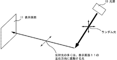
図1は、壁面や床面で反射した光が画像表示装置の表示画面に入射する様子のイメージ図である。図1に示すように、本発明者らは、蛍光灯等の光源10から照射されたランダム光が、上記壁面や床面で反射し、上記画像表示装置の表示画面11に入射して、明所コントラストを低下させ、視認性低下の原因となる反射光は、その多くが表示画面11の左右方向に振動した状態の光(ブリュースター角がより顕著な光、S偏光)となっていることに着目し、本発明の光学積層体を、上記光透過性基材の屈折率が大きい方向である遅相軸が、上記画像表示装置の表示画面の上下方向と平行に配置するものとしたのである。すなわち、本発明の光学積層体は、その用途を画像表示装置の表面に設置するものに限定し、この本発明の光学積層体を設置した画像表示装置は、上記光透過性基材の屈折率が大きい方向である遅相軸が、上記壁面や床面で反射した多くの光の振動方向に対して垂直な方向を向いた状態となっている。このように光透過性基材の屈折率が大きい方向である遅相軸の方向を特定の方向となるように光学積層体を設置してなる画像表示装置は、反射防止性能と明所コントラストとに優れたものとなる。
これは、上述した特定の状態で本発明の光学積層体を配置した構成の画像表示装置では、上記表示画面に入射する割合の多い左右方向に振動する光(S偏光)に対し、上記光透過性基材の屈折率が小さい方向である進相軸の方向が平行となり、最表面での外光反射が低減できるためである。
この理由は、Nなる屈折率を有する基材表面の反射率Rは、
R(%)=(N−1)2/(N+1)2
で表されるが、本発明の光学積層体における光透過性基材のような屈折率異方性を有する基材においては、画像表示装置において上記構成とすることにより、上記屈折率Nは、屈折率の小さい進相軸の屈折率が適用される割合が増加するからである。
また、上記理由によって、面内位相差を有する光透過性基材を用いた光学積層体であるにもかかわらず、画像表示装置への配置方向を考慮せずに光学積層体を設置した場合と、本発明のように、光透過性基材の屈折率が大きい方向である遅相軸の方向を特定の方向となるように光学積層体を設置した場合に、後者の場合の反射率が、前者の反射率よりも低くなっている。本発明における「反射防止性能が優れた状態」とは、このような状態のことを言う。
また、画像表示装置のコントラストは、暗所コントラストと明所コントラストとに分けられ、暗所コントラストは、(白表示の輝度/黒表示の輝度)として算出され、明所コントラストは、{(白表示の輝度+外光反射)/(黒表示の輝度+外光反射)}として算出される。いずれのコントラストの場合も分母の影響がより大きくなることで、コントラストが低下する。つまり、最表面での外光反射を低減できれば、結果として、明所コントラストが向上する。
なお、上記「上記光透過性基材の屈折率が大きい方向である遅相軸が、上記画像表示装置の表示画面の上下方向と平行に配置される」とは、上記遅相軸が、上記表示画面の上下方向に対して0°±40°の範囲で光学積層体が画像表示装置に配置された状態を意味する。
また、本発明の光学積層体において、上記光透過性基材の遅相軸と上記表示画面の上下方向との角度は、0°±30°であることが好ましく、0°±10°であることがより好ましく、0°±5°であることが更に好ましい。本発明の光学積層体において、上記光透過性基材の遅相軸と上記表示画面の上下方向との角度が0°±40°であることで、本発明の光学積層体による明所コントラストの向上を図ることができる。
なお、本発明の光学積層体では、上記光透過性基材の遅相軸と上記表示画面の上下方向との角度は0°であることが、明所コントラストの向上を図る上で最も好ましい。このため、上記光透過性基材の遅相軸と上記表示画面の上下方向との角度は、0°±40°であるよりも、0°±30°であることが好ましく、より好ましくは0°±10°となる。更に、上記光透過性基材の遅相軸と上記表示画面の上下方向との角度が0°±5°であると、該角度が0°である場合と同レベルの明所コントラストの向上を図ることができ、更に好ましい。
本明細書において、2つの軸のなす角度に関し、観察者側から見て、基準となる角度に対して時計回りになす角度をプラス(+)とし、基準となる角度に対して反時計回りになす角度をマイナス(−)とする。そして、特に表記せず角度を示した場合、基準となる角度に対して時計回りになす角度である場合(すなわち、プラスである場合)を意味する。
The optical layered body of the present invention has a light-transmitting base material having a birefringence index in the plane and is used by being disposed on the surface of an image display device. The light-transmitting base material has a refractive index of A slow axis that is a large direction is arranged in parallel with the vertical direction of the display screen of the image display device.
Here, since the image display device is normally installed and used indoors, reflection of light reflected from the wall surface or floor surface on the display screen (the surface of the optical laminate) of the image display device is prevented. By doing so, the antireflection performance can be made excellent.
FIG. 1 is an image diagram of light reflected from a wall surface or a floor surface entering a display screen of an image display device. As shown in FIG. 1, the present inventors reflect random light emitted from a light source 10 such as a fluorescent lamp on the wall surface or floor surface, enter the display screen 11 of the image display device, and brighten the light. The reflected light that lowers the contrast and causes a reduction in visibility is mostly light that vibrates in the left-right direction of the display screen 11 (light with a more remarkable Brewster angle, S-polarized light). Since the slow axis, which is the direction in which the refractive index of the light-transmitting substrate is large, is arranged in parallel with the vertical direction of the display screen of the image display device, the optical layered body of the present invention is arranged. is there. That is, the optical layered body of the present invention is limited to those for use on the surface of the image display device, and the image display device provided with the optical layered body of the present invention has the refractive index of the light-transmitting substrate. The slow axis, which is the direction in which the current is large, is in a state in which it is oriented in a direction perpendicular to the vibration direction of the many lights reflected on the wall surface and floor surface. Thus, the image display device in which the optical layered body is installed so that the direction of the slow axis, which is the direction in which the refractive index of the light-transmitting substrate is large, becomes a specific direction, has antireflection performance and bright place contrast. It will be excellent.
This is because, in the image display device having the configuration in which the optical layered body of the present invention is arranged in the specific state described above, the light transmission with respect to light (S-polarized light) that vibrates in the left-right direction with a large proportion of incidence on the display screen. This is because the direction of the fast axis, which is the direction in which the refractive index of the conductive substrate is small, becomes parallel, and external light reflection at the outermost surface can be reduced.
The reason for this is that the reflectance R of the substrate surface having a refractive index of N is:
R (%) = (N−1) 2 / (N + 1) 2
In the base material having refractive index anisotropy such as the light-transmitting base material in the optical layered body of the present invention, the refractive index N is set as follows in the image display device. This is because the rate at which the refractive index of the fast axis with a small refractive index is applied increases.
In addition, for the above reasons, the optical layered body is installed without considering the arrangement direction to the image display device, despite the optical layered body using the light-transmitting base material having the in-plane retardation. As in the present invention, when the optical laminate is installed so that the direction of the slow axis, which is the direction in which the refractive index of the light-transmitting substrate is large, is a specific direction, the reflectance in the latter case is It is lower than the former reflectance. The “state with excellent antireflection performance” in the present invention refers to such a state.
The contrast of the image display device is divided into a dark place contrast and a bright place contrast. The dark place contrast is calculated as (brightness of white display / brightness of black display), and the bright place contrast is {(white display brightness). Luminance + external light reflection) / (black display luminance + external light reflection)}. In any case of contrast, the influence of the denominator becomes larger and the contrast is lowered. That is, if the external light reflection at the outermost surface can be reduced, the bright place contrast is improved as a result.
The above-mentioned "the slow axis that is the direction in which the refractive index of the light transmissive substrate is large is arranged in parallel with the vertical direction of the display screen of the image display device" means that the slow axis is the above It means a state in which the optical laminated body is arranged on the image display device in the range of 0 ° ± 40 ° with respect to the vertical direction of the display screen.
In the optical layered body of the present invention, the angle between the slow axis of the light-transmitting substrate and the vertical direction of the display screen is preferably 0 ° ± 30 °, and is 0 ° ± 10 °. More preferably, 0 ° ± 5 ° is even more preferable. In the optical laminate of the present invention, the angle between the slow axis of the light-transmitting substrate and the vertical direction of the display screen is 0 ° ± 40 °, so that the contrast of the bright place by the optical laminate of the present invention is increased. Improvements can be made.
In the optical layered body of the present invention, the angle between the slow axis of the light-transmitting substrate and the vertical direction of the display screen is most preferably 0 ° from the viewpoint of improving the bright place contrast. For this reason, the angle between the slow axis of the light transmissive substrate and the vertical direction of the display screen is preferably 0 ° ± 30 °, more preferably 0 °, rather than 0 ° ± 40 °. ° ± 10 °. Furthermore, when the angle between the slow axis of the light-transmitting substrate and the vertical direction of the display screen is 0 ° ± 5 °, the bright contrast can be improved to the same level as when the angle is 0 °. This is more preferable.
In this specification, regarding the angle formed by the two axes, the angle formed clockwise with respect to the reference angle is plus (+) as viewed from the observer side, and is counterclockwise with respect to the reference angle. The angle formed is minus (−). When an angle is indicated without particular notation, it means a case where the angle is clockwise with respect to a reference angle (that is, a case where the angle is positive).
また、本発明の光学積層体では、上記画像表示装置の偏光子の吸収軸が、上記表示画面に対して左右方向である。
上記のように、画像表示装置の表示画面に入射する割合の多い左右方向に振動する光(S偏光)の本発明の光学積層体での反射を低減させることができるが、結果として、多くのS偏光が透過することとなる。通常、これらの透過したS偏光は、画像表示装置内部で吸収されるが、観測者側に戻ってくる光もごく僅かであるが存在する。しかしながら、本発明の光学積層体では、上記偏光子の吸収軸が、上記表示画面に対して左右方向であるため、本発明の光学積層体を透過したS偏光を吸収することができ、より観測者側に戻ってくる光を低下させ、その結果、表示画像をより優れたものとすることができる。
なお、「上記画像表示装置の偏光子の吸収軸が、上記表示画面に対して左右方向である」とは、上記吸収軸が上記表示画面の左右方向に対して0°±40°の範囲で、偏光子が画像表示装置に配置された状態を意味する。
また、本発明の光学積層体において、上記偏光子の吸収軸と上記表示画面の左右方向との角度は、0°±30°であることが好ましく、0°±10°であることがより好ましく、0°±5°であることが更に好ましい。本発明の光学積層体において、上記偏光子の吸収軸と上記表示画面の左右方向との角度が0°±40°であることで、上述した効果を得ることができる。
Moreover, in the optical laminated body of this invention, the absorption axis of the polarizer of the said image display apparatus is a left-right direction with respect to the said display screen.
As described above, it is possible to reduce reflection in the optical laminate of the present invention of light (S-polarized light) that vibrates in the left-right direction with a large proportion of incidence on the display screen of the image display device. S polarized light will be transmitted. Usually, the transmitted S-polarized light is absorbed inside the image display apparatus, but there is very little light returning to the observer side. However, in the optical layered body of the present invention, since the absorption axis of the polarizer is in the horizontal direction with respect to the display screen, S-polarized light transmitted through the optical layered body of the present invention can be absorbed, and more observation is performed. The light returning to the person side can be reduced, and as a result, the display image can be made more excellent.
Note that “the absorption axis of the polarizer of the image display device is in the horizontal direction with respect to the display screen” means that the absorption axis is in the range of 0 ° ± 40 ° with respect to the horizontal direction of the display screen. Means that the polarizer is disposed in the image display device.
In the optical layered body of the present invention, the angle between the absorption axis of the polarizer and the horizontal direction of the display screen is preferably 0 ° ± 30 °, and more preferably 0 ° ± 10 °. 0 ° ± 5 ° is more preferable. In the optical layered body of the present invention, the above-described effects can be obtained when the angle between the absorption axis of the polarizer and the left-right direction of the display screen is 0 ° ± 40 °.
上記面内に複屈折率を有する光透過性基材としては特に限定されず、例えば、ポリカーボネート、アクリル、ポリエステル等からなる基材が挙げられるが、なかでも、コスト及び機械的強度において有利なポリエステル基材であることが好適である。なお、以下の説明では、面内に複屈折率を有する光透過性基材をポリエステル基材として説明する。 The light-transmitting substrate having a birefringence in the plane is not particularly limited, and examples thereof include a substrate made of polycarbonate, acrylic, polyester, etc. Among them, polyester that is advantageous in cost and mechanical strength. A substrate is preferred. In the following description, a light-transmitting substrate having a birefringence in the plane will be described as a polyester substrate.
上記ポリエステル基材は、ニジムラ発生を防止でき、視認性改善が極めて良好となることから、リタデーションが3000nm以上であることが好ましい。3000nm未満であると、本発明の光学積層体を液晶表示装置(LCD)で使用した場合、虹色の縞模様のようなニジムラが視認され、表示品位が低下することがある。一方、上記ポリエステル基材のリタデーションの上限としては特に限定されないが、3万nm程度であることが好ましい。3万nmを超えると、膜厚が相当に厚くなるため好ましくない。
上記ポリエステル基材のリタデーションは、薄膜化の観点から、5000〜25000nmであることが好ましい。より好ましい範囲は、7000〜2万nmであり、この範囲であると、本発明の光学積層体が画像表示装置に、上記ポリエステル基材の遅相軸が、上記表示画面の上下方向に対して0°±30°〜40°の範囲で配置された場合、つまり、上記ポリエステル基材の遅相軸が、上記表示画面の上下方向に対して完全な平行よりも少しずれた角度を持って配置されている場合であっても、ニジムラ防止性を更に良好にできる。なお、本発明の光学積層体は、上記ポリエステル基材の遅相軸の配置が、上記表示画面の上下方向に対して完全な平行より±30°〜40°であっても、リタデーションが3000nm以上であれば、ニジムラ防止性を有し、実質使用上に問題はない。但し、上述のように、上記ポリエステル基材の遅相軸と上記表示画面の上下方向との角度は0°であることが最も好ましいので、上記ポリエステル基材の遅相軸と上記表示画面の上下方向との角度は、0°±10°であることがより好ましく、0°±5°であることが更に好ましい。
It is preferable that the polyester base material has a retardation of 3000 nm or more because it can prevent the occurrence of azimuth and the visibility is extremely improved. When it is less than 3000 nm, when the optical layered body of the present invention is used in a liquid crystal display device (LCD), a rainbow-colored stripe-like pattern may be visually recognized and display quality may deteriorate. On the other hand, the upper limit of the retardation of the polyester base material is not particularly limited, but is preferably about 30,000 nm. If it exceeds 30,000 nm, the film thickness becomes considerably large, which is not preferable.
It is preferable that the retardation of the said polyester base material is 5000-25000 nm from a viewpoint of thin film formation. A more preferable range is 7000 to 20,000 nm. When the range is within this range, the optical laminate of the present invention is applied to the image display device, and the slow axis of the polyester substrate is relative to the vertical direction of the display screen. When arranged in the range of 0 ° ± 30 ° -40 °, that is, the slow axis of the polyester base material is arranged with an angle slightly shifted from the completely parallel to the vertical direction of the display screen. Even if it is done, it is possible to further improve the anti-Nizimura property. The optical layered body of the present invention has a retardation of 3000 nm or more even when the slow axis of the polyester base material is ± 30 ° to 40 ° from the complete parallel to the vertical direction of the display screen. If it is, it has Nizimura prevention property and there is no problem in practical use. However, as described above, the angle between the slow axis of the polyester base and the vertical direction of the display screen is most preferably 0 °. The angle with the direction is more preferably 0 ° ± 10 °, and further preferably 0 ° ± 5 °.
なお、上記リタデーションとは、ポリエステル基材の面内において最も屈折率が大きい方向(遅相軸方向)の屈折率(nx)と、遅相軸方向と直交する方向(進相軸方向)の屈折率(ny)と、ポリエステル基材の厚み(d)とにより、以下の式によって表わされるものである。
リタデーション(Re)=(nx−ny)×d
また、上記リタデーションは、例えば、王子計測機器社製KOBRA−WRによって測定(測定角0°、測定波長589.3nm)することができる。
また、二枚の偏光板を用いて、ポリエステル基材の配向軸方向(主軸の方向)を求め、配向軸方向に対して直交する二つの軸の屈折率(nx、ny)を、アッベ屈折率計(アタゴ社製 NAR−4T)によって求める。ここで、より大きい屈折率を示す軸を遅相軸と定義する。ポリエステル基材厚みd(nm)は、電気マイクロメータ(アンリツ社製)を用いて測定し、単位をnmに換算する。屈折率差(nx−ny)と、フィルムの厚みd(nm)との積より、リタデーションを計算することもできる。
なお、屈折率は、アッベ屈折率計や、エリプソメーターを用いて測定することもできるし、分光光度計(島津製作所社製のUV−3100PC)を用いて、本発明の光学積層体が後述する光学機能層を有する場合、該光学機能層の波長380〜780nmの平均反射率(R)を測定し、得られた平均反射率(R)から、以下の式を用い、屈折率(n)の値を求めてもよい。
光学機能層の平均反射率(R)は、易接着処理のない50μmPET上にそれぞれの原料組成物を塗布し、1〜3μmの厚さの硬化膜にし、PETの塗布しなかった面(裏面)に、裏面反射を防止するために測定スポット面積よりも大きな幅の黒ビニールテープ(例えば、ヤマトビニールテープNo200−38−21 38mm幅)を貼ってから各硬化膜の平均反射率を測定した。ポリエステル基材の屈折率は、測定面とは反対面に同様に黒ビニールテープを貼ってから測定を行った。
R(%)=(1−n)2/(1+n)2
また、光学積層体となった後に光学機能層の屈折率を測定する方法としては、各層の硬化膜をカッターなどで削り取り、粉状態のサンプルを作製し、JIS K7142(2008)B法(粉体又は粒状の透明材料用)に従ったベッケ法を用いることができる。なお、上記ベッケ法とは、屈折率が既知のカーギル試薬を用い、上記粉状態のサンプルをスライドガラスなどに置き、そのサンプル上に試薬を滴下し、試薬でサンプルを浸漬する。その様子を顕微鏡観察によって観察し、サンプルと試薬の屈折率が異なることによってサンプル輪郭に生じる輝線;ベッケ線が目視で観察できなくなる試薬の屈折率を、サンプルの屈折率とする方法である。
なお、ポリエステル基材の場合は、方向によって屈折率(nx、ny)が異なるので、ベッケ法ではなく、光学機能層の処理面に上記黒ビニールテープを貼ることで、分光光度計(V7100型、自動絶対反射率測定ユニットVAR−7010 日本分光社製)を用いて、偏光測定:S偏光にて、光透過性基材の遅相軸を平行に設置した場合と、進相軸を平行に設置した場合との5度反射率を測定し、遅相軸と進相軸の屈折率(nx、ny)を上記式より算出もできる。
The retardation is the refractive index (nx) in the direction having the highest refractive index (slow axis direction) in the plane of the polyester substrate, and the refraction in the direction orthogonal to the slow axis direction (fast axis direction). It is represented by the following formula by the rate (ny) and the thickness (d) of the polyester base material.
Retardation (Re) = (nx−ny) × d
The retardation can be measured, for example, by KOBRA-WR manufactured by Oji Scientific Instruments (measurement angle 0 °, measurement wavelength 589.3 nm).
Further, using two polarizing plates, the orientation axis direction (principal axis direction) of the polyester substrate is obtained, and the refractive indexes (nx, ny) of two axes orthogonal to the orientation axis direction are Abbe's refractive indices. It calculates | requires by the total (NAGO-4T by Atago Co., Ltd.). Here, an axis showing a larger refractive index is defined as a slow axis. The polyester base material thickness d (nm) is measured using an electric micrometer (manufactured by Anritsu), and the unit is converted to nm. Retardation can also be calculated from the product of the refractive index difference (nx−ny) and the thickness d (nm) of the film.
In addition, a refractive index can also be measured using an Abbe refractometer and an ellipsometer, and the optical laminated body of this invention is mentioned later using a spectrophotometer (Shimadzu UV-3100PC). When having an optical functional layer, the average reflectance (R) of the optical functional layer at a wavelength of 380 to 780 nm is measured, and from the obtained average reflectance (R), the refractive index (n) A value may be obtained.
The average reflectance (R) of the optical functional layer is a surface (back surface) on which 50 μm PET without easy adhesion treatment is coated with each raw material composition to form a cured film having a thickness of 1 to 3 μm, and PET is not applied. In order to prevent back surface reflection, the average reflectance of each cured film was measured after applying a black vinyl tape (for example, Yamato vinyl tape No 200-38-21 38 mm width) having a width larger than the measurement spot area. The refractive index of the polyester base material was measured after black vinyl tape was similarly applied to the surface opposite to the measurement surface.
R (%) = (1-n) 2 / (1 + n) 2
Further, as a method for measuring the refractive index of the optical functional layer after becoming an optical layered product, a cured film of each layer is scraped off with a cutter or the like to prepare a powder sample, and JIS K7142 (2008) B method (powder) Alternatively, the Becke method according to (for granular transparent materials) can be used. In the Becke method, a Cargill reagent having a known refractive index is used, the powder sample is placed on a glass slide, the reagent is dropped on the sample, and the sample is immersed in the reagent. This is observed by using a microscope, and this is a method in which the refractive index of the sample is the refractive index of the reagent in which the bright line generated in the sample outline due to the difference in refractive index between the sample and the reagent;
In the case of a polyester base material, the refractive index (nx, ny) varies depending on the direction. Therefore, instead of the Becke method, the above-mentioned black vinyl tape is applied to the treated surface of the optical functional layer, so that a spectrophotometer (V7100 type, Automatic absolute reflectance measurement unit VAR-7010 (manufactured by JASCO Corporation), polarization measurement: S-polarized light, the slow axis of the light-transmitting substrate is installed in parallel, and the fast axis is installed in parallel In this case, the reflectivity (nx, ny) of the slow axis and the fast axis can be calculated from the above formula.
なお、本発明では、上記ポリエステル基材が後述するポリエチレンテレフタレート(PET)を原料とするPET基材である場合、上記nx−ny(以下、Δnとも表記する)は、0.05以上であることが好ましい。上記Δnが0.05未満であると、進相軸の屈折率が大きいため、上述した画像表示装置の明所コントラストの向上が図れないことがある。更に、上述したリタデーション値を得るために必要な膜厚が厚くなってしまうことがある。一方、上記Δnは、0.25以下であることが好ましい。0.25を超えると、PET基材を過度に延伸する必要が生じるため、PET基材が裂け、破れ等を生じやすくなり、工業材料としての実用性が著しく低下することがある。
以上の観点から、上記PET基材である場合のΔnのより好ましい下限は0.07、より好ましい上限は0.20である。なお、上記Δnが0.20を超えると、耐湿熱性試験でのPET基材の耐久性が劣ることがある。耐湿熱性試験での耐久性が優れることから、上記PET基材である場合のΔnの更に好ましい上限は0.15である。
なお、上記PET基材である場合の(nx)としては、1.66〜1.78であることが好ましく、より好ましい下限は1.68、より好ましい上限は1.73である。また、上記PET基材である場合の(ny)としては、1.55〜1.65であることが好ましく、より好ましい下限は1.57、より好ましい上限は1.62である。
上記nx及びnyが上記範囲にあり、かつ、上述したΔnの関係を満たすことで、好適な反射防止性能及び明所コントラストの向上を図ることができる。
また、上記ポリエステル基材が後述するポリエチレンナフタレート(PEN)を原料とするPEN基材である場合、上記Δnは、好ましい下限が0.05であり、好ましい上限が0.30である。上記Δnが0.05未満であると、上述したリタデーション値を得るために必要な膜厚が厚くなるため、好ましくない。一方、上記Δnが0.30を超えると、PEN基材として、裂け、破れ等を生じやすくなり、工業材料としての実用性が著しく低下することがある。上記PEN基材である場合のΔnのより好ましい下限は0.07、より好ましい上限は0.27である。Δnが0.07よりも小さいと、上述した充分なニジムラ及び色味変化の抑制効果を得にくくなるためである。なお、上記Δnが0.27を超えると、耐湿熱性試験でのPEN基材の耐久性が劣ることがある。また、耐湿熱性試験での耐久性が優れることから、上記PEN基材である場合のΔnの更に好ましい上限は0.25である。
なお、上記PEN基材である場合の(nx)としては、1.70〜1.90であることが好ましく、より好ましい下限は1.72、より好ましい上限は1.88である。また、上記PEN基材である場合の(ny)としては、1.55〜1.75であることが好ましく、より好ましい下限は1.57、より好ましい上限は1.73である。
In the present invention, when the polyester base material is a PET base material made of polyethylene terephthalate (PET) described later, the nx-ny (hereinafter also referred to as Δn) is 0.05 or more. Is preferred. If Δn is less than 0.05, the fast axis refractive index is large, and thus the above-described image display apparatus may not be improved in bright place contrast. Further, the film thickness necessary for obtaining the retardation value described above may be increased. On the other hand, the Δn is preferably 0.25 or less. If it exceeds 0.25, it becomes necessary to stretch the PET base material excessively, so that the PET base material is likely to be torn and torn, and the practicality as an industrial material may be significantly reduced.
From the above viewpoint, the more preferable lower limit of Δn in the case of the PET substrate is 0.07, and the more preferable upper limit is 0.20. In addition, when said (DELTA) n exceeds 0.20, the durability of the PET base material in a heat-and-moisture resistance test may be inferior. Since the durability in the wet heat resistance test is excellent, the more preferable upper limit of Δn in the case of the PET base material is 0.15.
In addition, as (nx) in the case of the said PET base material, it is preferable that it is 1.66-1.78, a more preferable minimum is 1.68, and a more preferable upper limit is 1.73. Moreover, as (ny) in the case of the said PET base material, it is preferable that it is 1.55-1.65, a more preferable minimum is 1.57 and a more preferable upper limit is 1.62.
When nx and ny are in the above-described range and satisfy the above-described relationship of Δn, it is possible to improve suitable antireflection performance and bright place contrast.
Moreover, when the said polyester base material is a PEN base material which uses the polyethylene naphthalate (PEN) mentioned later as a raw material, as for said (DELTA) n, a preferable minimum is 0.05 and a preferable upper limit is 0.30. If Δn is less than 0.05, the film thickness necessary to obtain the retardation value described above is increased, which is not preferable. On the other hand, if the above Δn exceeds 0.30, the PEN substrate tends to be torn and torn, and the practicality as an industrial material may be significantly reduced. The more preferable lower limit of Δn in the case of the PEN substrate is 0.07, and the more preferable upper limit is 0.27. This is because if Δn is smaller than 0.07, it is difficult to obtain the sufficient effect of suppressing the above-mentioned azimuth and color change. In addition, when said (DELTA) n exceeds 0.27, durability of the PEN base material in a heat-and-moisture resistance test may be inferior. Moreover, since the durability in a heat-and-moisture resistance test is excellent, a more preferable upper limit of Δn in the case of the PEN substrate is 0.25.
In addition, as (nx) in the case of the said PEN base material, it is preferable that it is 1.70-1.90, a more preferable minimum is 1.72 and a more preferable upper limit is 1.88. Moreover, as (ny) in the case of the said PEN base material, it is preferable that it is 1.55-1.75, a more preferable minimum is 1.57 and a more preferable upper limit is 1.73.
上記ポリエステル基材を構成する材料としては、上述したリタデーションを充足するものであれば特に限定されないが、芳香族二塩基酸又はそのエステル形成性誘導体とジオール又はそのエステル形成性誘導体とから合成される線状飽和ポリエステルが挙げられる。かかるポリエステルの具体例として、ポリエチレンテレフタレート、ポリエチレンイソフタレート、ポリブチレンテレフタレート、ポリ(1,4−シクロヘキシレンジメチレンテレフタレート)、ポリエチレンナフタレート(ポリエチレン−2,6−ナフタレート、ポリエチレン−1,4−ナフタレート、ポリエチレン−1,5−ナフタレート、ポリエチレン−2,7−ナフタレート、ポリエチレン−2,3−ナフタレート)などを例示することができる。また、ポリエステル基材に用いられるポリエステルは、これらのポリエステルの共重合体であってもよく、上記ポリエステルを主体(例えば80モル%以上の成分)とし、少割合(例えば20モル%以下)の他の種類の樹脂とブレンドしたものであってもよい。上記ポリエステルとしてポリエチレンテレフタレート又はポリエチレンナフタレートが力学的物性や光学物性等のバランスが良いので特に好ましい。特に、ポリエチレンテレフタレート(PET)からなることが好ましい。ポリエチレンテレフタレートは汎用性が高く、入手が容易であるからである。本発明においてはPETのような、汎用性が極めて高いフィルムであっても、表示品質の高い液晶表示装置を作製することが可能な、光学積層体を得ることができる。更に、PETは、透明性、熱又は機械的特性に優れ、延伸加工によりリタデーションの制御が可能であり、固有複屈折が大きく、膜厚が薄くても比較的容易に大きなリタデーションが得られる。 The material constituting the polyester base material is not particularly limited as long as it satisfies the retardation described above, but is synthesized from an aromatic dibasic acid or an ester-forming derivative thereof and a diol or an ester-forming derivative thereof. Examples include linear saturated polyester. Specific examples of such polyester include polyethylene terephthalate, polyethylene isophthalate, polybutylene terephthalate, poly (1,4-cyclohexylenedimethylene terephthalate), polyethylene naphthalate (polyethylene-2,6-naphthalate, polyethylene-1,4-naphthalate). , Polyethylene-1,5-naphthalate, polyethylene-2,7-naphthalate, polyethylene-2,3-naphthalate) and the like. The polyester used for the polyester substrate may be a copolymer of these polyesters. The polyester is mainly used (for example, a component of 80 mol% or more), and a small proportion (for example, 20 mol% or less). It may be blended with these types of resins. Polyethylene terephthalate or polyethylene naphthalate is particularly preferable as the polyester because of good balance between mechanical properties and optical properties. In particular, it is preferably made of polyethylene terephthalate (PET). This is because polyethylene terephthalate is highly versatile and easily available. In the present invention, an optical laminate that can produce a liquid crystal display device with high display quality can be obtained even with a highly versatile film such as PET. Furthermore, PET is excellent in transparency, heat or mechanical properties, can control the retardation by stretching, has a large intrinsic birefringence, and can obtain a large retardation relatively easily even when the film thickness is small.
上記ポリエステル基材を得る方法としては、上述したリタデーションを充足する方法であれば特に限定されないが、例えば、材料の上記PET等のポリエステルを溶融し、シート状に押出し成形された未延伸ポリエステルをガラス転移温度以上の温度においてテンター等を用いて横延伸後、熱処理を施す方法が挙げられる。
上記横延伸温度としては、80〜130℃が好ましく、より好ましくは90〜120℃である。また、横延伸倍率は2.5〜6.0倍が好ましく、より好ましくは3.0〜5.5倍である。上記横延伸倍率が6.0倍を超えると、得られるポリエステル基材の透明性が低下しやすくなり、横延伸倍率が2.5倍未満であると、延伸張力も小さくなるため、得られるポリエステル基材の複屈折が小さくなり、リタデーションを3000nm以上とできないことがある。
また、本発明においては、二軸延伸試験装置を用いて、上記未延伸ポリエステルの横延伸を上記条件で行った後、該横延伸に対する流れ方向の延伸(以下、縦延伸ともいう)を行ってもよい。この場合、上記縦延伸は、延伸倍率が2倍以下であることが好ましい。上記縦延伸の延伸倍率が2倍を超えると、Δnの値を上述した好ましい範囲にできないことがある。
また、上記熱処理時の処理温度はしては、100〜250℃が好ましく、より好ましくは180〜245℃である。
ここで、従来のポリエステル基材は、未延伸のポリエステル基材を長手方向に延伸させた後に、幅方向に長手方向と同程度の倍率で延伸させることによって得られていた。しかしながら、このような延伸方法で得られたポリエステル基材では、ボーイング現象が発生しやすいという問題があった。これに対し、本発明における上記リタデーション値を有するポリエステル基材は、ロール状の未延伸の光透過性フィルムを幅方向のみに延伸させ、又は、縦方向に僅かに延伸させた後に幅方向に延伸させることで得ることができる。このようにして得られたポリエステル基材は、上記ボーイング現象の発生を抑制でき、また、その遅相軸が幅方向に沿って存在していることとなる。
また、本発明の光学積層体は、後述するが偏光素子上に設けて偏光板とすることができるが、ロール状の上記偏光素子は、長手方向に沿って吸収軸が存在している。このため、ロールツーロール法によって上記光透過性基材と上記偏光素子とを貼り合わせると、偏光素子の吸収軸と光透過性基材の遅相軸とのなす角度が垂直となった偏光板を形成することができる。このような光透過性基材の遅相軸と偏光素子の吸収軸とのなす角度については、後で詳述する。
The method for obtaining the polyester base material is not particularly limited as long as the above-described retardation is satisfied. For example, the polyester, such as PET, as a material is melted and extruded into a sheet to form glass. The method of heat-processing after transverse stretching using a tenter etc. at the temperature more than transition temperature is mentioned.
The transverse stretching temperature is preferably 80 to 130 ° C, more preferably 90 to 120 ° C. Further, the transverse draw ratio is preferably 2.5 to 6.0 times, more preferably 3.0 to 5.5 times. When the transverse draw ratio exceeds 6.0 times, the transparency of the resulting polyester base material tends to be lowered, and when the transverse draw ratio is less than 2.5 times, the draw tension becomes small. In some cases, the birefringence of the substrate becomes small, and the retardation cannot be increased to 3000 nm or more.
In the present invention, the unstretched polyester is subjected to transverse stretching under the above conditions using a biaxial stretching test apparatus, and then stretched in the flow direction with respect to the transverse stretching (hereinafter also referred to as longitudinal stretching). Also good. In this case, the longitudinal stretching preferably has a stretching ratio of 2 times or less. When the draw ratio of the above-mentioned longitudinal stretching exceeds twice, the value of Δn may not be within the preferred range described above.
The treatment temperature during the heat treatment is preferably 100 to 250 ° C, more preferably 180 to 245 ° C.
Here, the conventional polyester base material has been obtained by stretching an unstretched polyester base material in the longitudinal direction and then stretching the unstretched polyester base material in the width direction at the same degree as the longitudinal direction. However, the polyester base material obtained by such a stretching method has a problem that the bowing phenomenon easily occurs. On the other hand, the polyester base material having the retardation value in the present invention is obtained by stretching a roll-shaped unstretched light-transmitting film only in the width direction or slightly stretching in the longitudinal direction and then stretching in the width direction. Can be obtained. The polyester base material obtained in this way can suppress the occurrence of the bowing phenomenon, and its slow axis exists along the width direction.
Although the optical layered body of the present invention can be provided on a polarizing element to be a polarizing plate as will be described later, the roll-shaped polarizing element has an absorption axis along the longitudinal direction. Therefore, when the light transmissive substrate and the polarizing element are bonded together by a roll-to-roll method, the angle between the absorption axis of the polarizing element and the slow axis of the light transmissive substrate is vertical. Can be formed. The angle formed between the slow axis of the light-transmitting substrate and the absorption axis of the polarizing element will be described in detail later.
上述した方法で作製したポリエステル基材のリタデーションを3000nm以上に制御する方法としては、延伸倍率や延伸温度、作製するポリエステル基材の膜厚を適宜設定する方法が挙げられる。具体的には、例えば、延伸倍率が高いほど、延伸温度が低いほど、また、膜厚が厚いほど、高いリタデーションを得やすくなり、延伸倍率が低いほど、延伸温度が高いほど、また、膜厚が薄いほど、低いリタデーションを得やすくなる。 Examples of the method for controlling the retardation of the polyester substrate produced by the above-described method to 3000 nm or more include a method of appropriately setting the draw ratio, the drawing temperature, and the film thickness of the produced polyester substrate. Specifically, for example, the higher the stretching ratio, the lower the stretching temperature, and the thicker the film, the easier it is to obtain high retardation. The lower the stretching ratio, the higher the stretching temperature, and the film thickness. The thinner, the easier it is to obtain low retardation.
上記ポリエステル基材の厚みとしては、40〜500μmの範囲内であることが好ましい。40μm未満であると、上記ポリエステル基材のリタデーションを3000nm以上にできず、また、力学特性の異方性が顕著となり、裂け、破れ等を生じやすくなり、工業材料としての実用性が著しく低下することがある。一方、500μmを超えると、ポリエステル基材が非常に剛直であり、高分子フィルム特有のしなやかさが低下し、やはり工業材料としての実用性が低下するので好ましくない。上記ポリエステル基材の厚さのより好ましい下限は50μm、より好ましい上限は400μmであり、更に好ましい上限は300μmである。 The thickness of the polyester substrate is preferably in the range of 40 to 500 μm. When the thickness is less than 40 μm, the retardation of the polyester base material cannot be increased to 3000 nm or more, the anisotropy of mechanical properties becomes remarkable, and tearing, tearing, and the like easily occur, and the practicality as an industrial material is remarkably reduced. Sometimes. On the other hand, if it exceeds 500 μm, the polyester base material is very rigid, the flexibility specific to the polymer film is lowered, and the practicality as an industrial material is also lowered, which is not preferable. The minimum with more preferable thickness of the said polyester base material is 50 micrometers, a more preferable upper limit is 400 micrometers, and a still more preferable upper limit is 300 micrometers.
また、上記ポリエステル基材は、可視光領域における透過率が80%以上であることが好ましく、84%以上であるものがより好ましい。なお、上記透過率は、JIS K7361−1(プラスチック−透明材料の全光透過率の試験方法)により測定することができる。 The polyester base material preferably has a transmittance in the visible light region of 80% or more, more preferably 84% or more. In addition, the said transmittance | permeability can be measured by JISK7361-1 (The test method of the total light transmittance of a plastic-transparent material).
また、本発明において、上記ポリエステル基材には本発明の趣旨を逸脱しない範囲で、けん化処理、グロー放電処理、コロナ放電処理、紫外線(UV)処理、及び火炎処理等の表面処理を行ってもよい。 In the present invention, the polyester substrate may be subjected to surface treatment such as saponification treatment, glow discharge treatment, corona discharge treatment, ultraviolet (UV) treatment, and flame treatment without departing from the spirit of the present invention. Good.
本発明の光学積層体は、上記光透過性基材の一方の面上に光学機能層を有することが好ましく、上記光透過性基材の遅相軸方向の屈折率を(nx)、上記遅相軸方向と直交する方向である進相軸方向の屈折率を(ny)としたときに、上記光学機能層の屈折率が(nx+ny)/2未満であることが好ましい。上記光学機能層の屈折率が(nx+ny)/2以上であると、該光学機能層の屈折率と上記光透過性基材の遅相軸方向の屈折率との差が、上記光透過性基材の進相軸方向の屈折率との差よりも小さくなるため、反射防止性能と明所コントラストとを優れるという効果を得るためには、上記光透過性基材の屈折率が大きい方向である遅相軸を、上記画像表示装置の表示画面の上下方向と平行ではなく、該表示画面の左右方向に平行となるように配置することが好ましくなる。また、屈折率が(nx+ny)/2以上となるような材料は、屈折率が(nx+ny)/2未満となるような材料と比較して、一般的に高価であり、光学機能層の硬度等の特性にも劣ることがある。 The optical layered body of the present invention preferably has an optical functional layer on one surface of the light transmissive substrate, and the refractive index in the slow axis direction of the light transmissive substrate is (nx), When the refractive index in the fast axis direction, which is a direction orthogonal to the phase axis direction, is (ny), the refractive index of the optical functional layer is preferably less than (nx + ny) / 2. When the refractive index of the optical functional layer is (nx + ny) / 2 or more, the difference between the refractive index of the optical functional layer and the refractive index in the slow axis direction of the light transmissive substrate is the light transmissive group. Since it is smaller than the difference between the refractive index in the fast axis direction of the material, in order to obtain the effect of excellent antireflection performance and bright place contrast, the refractive index of the light-transmitting base material is the direction in which it is large. It is preferable to arrange the slow axis so as not to be parallel to the vertical direction of the display screen of the image display device but to be parallel to the horizontal direction of the display screen. In addition, a material having a refractive index of (nx + ny) / 2 or higher is generally more expensive than a material having a refractive index of less than (nx + ny) / 2, and the hardness of the optical functional layer, etc. There are also inferior characteristics.
また、上記光学機能層は、ハードコート性能を有するハードコート層であることが好ましく、該ハードコート層は、硬度が、JIS K5600−5−4(1999)による鉛筆硬度試験(荷重4.9N)において、H以上であることが好ましく、2H以上であることがより好ましい。
上記ハードコート層は、本発明の光学積層体の表面のハードコート性を担保する層であり、例えば、紫外線により硬化する樹脂である電離放射線硬化型樹脂と光重合開始剤とを含有するハードコート層用組成物を用いて形成されたものであることが好ましい。
The optical functional layer is preferably a hard coat layer having a hard coat performance, and the hard coat layer has a hardness of a pencil hardness test according to JIS K5600-5-4 (1999) (load 4.9 N). Is preferably H or more, more preferably 2H or more.
The hard coat layer is a layer that ensures the hard coat properties of the surface of the optical laminate of the present invention, and includes, for example, a hard coat containing an ionizing radiation curable resin that is a resin curable by ultraviolet rays and a photopolymerization initiator. It is preferable that it is formed using the layer composition.
本発明の光学積層体において、上記電離放射線硬化型樹脂としては、例えば、アクリレート系の官能基を有する化合物等の1又は2以上の不飽和結合を有する化合物を挙げることができる。1の不飽和結合を有する化合物としては、例えば、エチル(メタ)アクリレート、エチルヘキシル(メタ)アクリレート、スチレン、メチルスチレン、N−ビニルピロリドン等を挙げることができる。2以上の不飽和結合を有する化合物としては、例えば、ポリメチロールプロパントリ(メタ)アクリレート、トリプロピレングリコールジ(メタ)アクリレート、ジエチレングリコールジ(メタ)アクリレート、ペンタエリスリトールトリ(メタ)アクリレート、ペンタエリスリトールテトラ(メタ)アクリレート、ジペンタエリスリトールヘキサ(メタ)アクリレート、ジペンタエリスリトールペンタ(メタ)アクリレート、1,6−ヘキサンジオールジ(メタ)アクリレート、ネオペンチルグリコールジ(メタ)アクリレート等及びこれらをエチレンオキサイド(EО)等で変性した多官能化合物、又は、上記多官能化合物と(メタ)アクリレート等の反応生成物(例えば多価アルコールのポリ(メタ)アクリレートエステル)等を挙げることができる。なお、本明細書において「(メタ)アクリレート」は、メタクリレート及びアクリレートを指すものである。 In the optical layered body of the present invention, examples of the ionizing radiation curable resin include compounds having one or more unsaturated bonds, such as a compound having an acrylate functional group. Examples of the compound having one unsaturated bond include ethyl (meth) acrylate, ethylhexyl (meth) acrylate, styrene, methylstyrene, N-vinylpyrrolidone and the like. Examples of the compound having two or more unsaturated bonds include polymethylolpropane tri (meth) acrylate, tripropylene glycol di (meth) acrylate, diethylene glycol di (meth) acrylate, pentaerythritol tri (meth) acrylate, pentaerythritol tetra (Meth) acrylate, dipentaerythritol hexa (meth) acrylate, dipentaerythritol penta (meth) acrylate, 1,6-hexanediol di (meth) acrylate, neopentyl glycol di (meth) acrylate, and the like, and ethylene oxide ( A polyfunctional compound modified with EEO), or a reaction product of the polyfunctional compound and (meth) acrylate (for example, poly (meth) acrylate ester of polyhydric alcohol). It is possible. In the present specification, “(meth) acrylate” refers to methacrylate and acrylate.
上記化合物のほかに、不飽和二重結合を有する比較的低分子量(数平均分子量300〜8万、好ましくは400〜5000)のポリエステル樹脂、ポリエーテル樹脂、アクリル樹脂、エポキシ樹脂、ウレタン樹脂、アルキッド樹脂、スピロアセタール樹脂、ポリブタジエン樹脂、ポリチオールポリエン樹脂等も上記電離放射線硬化型樹脂として使用することができる。なお、この場合の樹脂とは、モノマー以外のダイマー、オリゴマー、ポリマー全てを含む。
本発明における好ましい化合物としては、3以上の不飽和結合を有する化合物が挙げられる。このような化合物を用いると形成するハードコート層の架橋密度を高めることができ、塗硬度を良好にできる。
具体的には、本発明においては、ペンタエリスリトールトリアクリレート、ペンタエリスリトールテトラアクリレート、ポリエステル多官能アクリレートオリゴマー(3〜15官能)、ウレタン多官能アクリレートオリゴマー(3〜15官能)等を適宜組み合わせて用いることが好ましい。
In addition to the above compounds, polyester resins, polyether resins, acrylic resins, epoxy resins, urethane resins, alkyds having a relatively low molecular weight (number average molecular weight of 300 to 80,000, preferably 400 to 5000) having an unsaturated double bond. Resins, spiroacetal resins, polybutadiene resins, polythiol polyene resins, and the like can also be used as the ionizing radiation curable resin. The resin in this case includes all dimers, oligomers, and polymers other than monomers.
Preferred compounds in the present invention include compounds having 3 or more unsaturated bonds. When such a compound is used, the crosslink density of the hard coat layer to be formed can be increased, and the coating hardness can be improved.
Specifically, in the present invention, pentaerythritol triacrylate, pentaerythritol tetraacrylate, polyester polyfunctional acrylate oligomer (3 to 15 functional), urethane polyfunctional acrylate oligomer (3 to 15 functional) and the like are used in appropriate combination. Is preferred.
上記電離放射線硬化型樹脂は、溶剤乾燥型樹脂と併用して使用することもできる。溶剤乾燥型樹脂を併用することによって、塗布面の被膜欠陥を有効に防止することができる。なお、上記溶剤乾燥型樹脂とは、熱可塑性樹脂等、塗工時に固形分を調整するために添加した溶剤を乾燥させるだけで、被膜となるような樹脂をいう。
上記電離放射線硬化型樹脂と併用して使用することができる溶剤乾燥型樹脂としては特に限定されず、一般に、熱可塑性樹脂を使用することができる。
上記熱可塑性樹脂としては特に限定されず、例えば、スチレン系樹脂、(メタ)アクリル系樹脂、酢酸ビニル系樹脂、ビニルエーテル系樹脂、ハロゲン含有樹脂、脂環式オレフィン系樹脂、ポリカーボネート系樹脂、ポリエステル系樹脂、ポリアミド系樹脂、セルロース誘導体、シリコーン系樹脂及びゴム又はエラストマー等を挙げることができる。上記熱可塑性樹脂は、非結晶性で、かつ有機溶媒(特に複数のポリマーや硬化性化合物を溶解可能な共通溶媒)に可溶であることが好ましい。特に、製膜性、透明性や耐候性の観点から、スチレン系樹脂、(メタ)アクリル系樹脂、脂環式オレフィン系樹脂、ポリエステル系樹脂、セルロース誘導体(セルロースエステル類等)等が好ましい。
The ionizing radiation curable resin can be used in combination with a solvent-drying resin. By using the solvent-drying resin in combination, film defects on the coated surface can be effectively prevented. In addition, the said solvent dry type resin means resin which becomes a film only by drying the solvent added in order to adjust solid content at the time of coating, such as a thermoplastic resin.
The solvent-drying resin that can be used in combination with the ionizing radiation curable resin is not particularly limited, and a thermoplastic resin can be generally used.
The thermoplastic resin is not particularly limited. For example, a styrene resin, a (meth) acrylic resin, a vinyl acetate resin, a vinyl ether resin, a halogen-containing resin, an alicyclic olefin resin, a polycarbonate resin, or a polyester resin. Examples thereof include resins, polyamide-based resins, cellulose derivatives, silicone-based resins, rubbers, and elastomers. The thermoplastic resin is preferably amorphous and soluble in an organic solvent (particularly a common solvent capable of dissolving a plurality of polymers and curable compounds). In particular, from the viewpoint of film forming properties, transparency, and weather resistance, styrene resins, (meth) acrylic resins, alicyclic olefin resins, polyester resins, cellulose derivatives (cellulose esters, etc.) and the like are preferable.
また、上記ハードコート層用組成物は、熱硬化性樹脂を含有していてもよい。
上記熱硬化性樹脂としては特に限定されず、例えば、フェノール樹脂、尿素樹脂、ジアリルフタレート樹脂、メラミン樹脂、グアナミン樹脂、不飽和ポリエステル樹脂、ポリウレタン樹脂、エポキシ樹脂、アミノアルキッド樹脂、メラミン−尿素共縮合樹脂、ケイ素樹脂、ポリシロキサン樹脂等を挙げることができる。
Moreover, the said composition for hard-coat layers may contain the thermosetting resin.
The thermosetting resin is not particularly limited. For example, phenol resin, urea resin, diallyl phthalate resin, melamine resin, guanamine resin, unsaturated polyester resin, polyurethane resin, epoxy resin, aminoalkyd resin, melamine-urea cocondensation Examples thereof include resins, silicon resins, polysiloxane resins, and the like.
上記光重合開始剤としては特に限定されず、公知のものを用いることができ、例えば、上記光重合開始剤としては、具体例には、アセトフェノン類、ベンゾフェノン類、ミヒラーベンゾイルベンゾエート、α−アミロキシムエステル、チオキサントン類、プロピオフェノン類、ベンジル類、ベンゾイン類、アシルホスフィンオキシド類が挙げられる。また、光増感剤を混合して用いることが好ましく、その具体例としては、例えば、n−ブチルアミン、トリエチルアミン、ポリ−n−ブチルホスフィン等が挙げられる。 The photopolymerization initiator is not particularly limited, and known ones can be used. For example, specific examples of the photopolymerization initiator include acetophenones, benzophenones, Michler benzoylbenzoate, α-amylo. Examples include oxime esters, thioxanthones, propiophenones, benzyls, benzoins, and acylphosphine oxides. In addition, it is preferable to use a mixture of photosensitizers, and specific examples thereof include n-butylamine, triethylamine, poly-n-butylphosphine, and the like.
上記光重合開始剤としては、上記電離放射線硬化型樹脂がラジカル重合性不飽和基を有する樹脂系の場合は、アセトフェノン類、ベンゾフェノン類、チオキサントン類、ベンゾイン、ベンゾインメチルエーテル等を単独又は混合して用いることが好ましい。また、上記電離放射線硬化型樹脂がカチオン重合性官能基を有する樹脂系の場合は、上記光重合開始剤としては、芳香族ジアゾニウム塩、芳香族スルホニウム塩、芳香族ヨードニウム塩、メタロセン化合物、ベンゾインスルホン酸エステル等を単独又は混合物として用いることが好ましい。
本発明において用いる開始剤としては、ラジカル重合性不飽和基を有する電離放射線硬化型樹脂の場合は、1−ヒドロキシ−シクロヘキシル−フェニル−ケトンが、電離放射線硬化型樹脂との相溶性、及び、黄変も少ないという理由から好ましい。
As the photopolymerization initiator, when the ionizing radiation curable resin is a resin system having a radical polymerizable unsaturated group, acetophenones, benzophenones, thioxanthones, benzoin, benzoin methyl ether, etc. may be used alone or in combination. It is preferable to use it. When the ionizing radiation curable resin is a resin system having a cationic polymerizable functional group, the photopolymerization initiator may be an aromatic diazonium salt, aromatic sulfonium salt, aromatic iodonium salt, metallocene compound, benzoin sulfone. It is preferable to use acid esters alone or as a mixture.
As the initiator used in the present invention, in the case of an ionizing radiation curable resin having a radically polymerizable unsaturated group, 1-hydroxy-cyclohexyl-phenyl-ketone is compatible with the ionizing radiation curable resin, and yellow This is preferable because of little change.
上記ハードコート層用組成物にける上記光重合開始剤の含有量は、上記電離放射線硬化型樹脂100質量部に対して、1〜10質量部であることが好ましい。1質量部未満であると、第1の本発明の光学積層体におけるハードコート層の硬度を上述した範囲とすることができないことがあり、10質量部を超えると、塗設した膜の深部まで電離放射線が届かなくなり内部硬化が促進されず、目標であるハードコート層の表面の鉛筆硬度3H以上が得られないおそれがあるためである。
上記光重合開始剤の含有量のより好ましい下限は2質量部であり、より好ましい上限は8質量部である。上記光重合開始剤の含有量がこの範囲にあることで、膜厚方向に硬度分布が発生せず、均一な硬度になりやすくなる。
The content of the photopolymerization initiator in the hard coat layer composition is preferably 1 to 10 parts by mass with respect to 100 parts by mass of the ionizing radiation curable resin. When the amount is less than 1 part by mass, the hardness of the hard coat layer in the optical laminate of the first invention may not be within the above-described range. This is because the ionizing radiation does not reach and internal curing is not promoted, and there is a risk that the pencil hardness of 3H or higher on the surface of the target hard coat layer may not be obtained.
The minimum with more preferable content of the said photoinitiator is 2 mass parts, and a more preferable upper limit is 8 mass parts. When the content of the photopolymerization initiator is in this range, a hardness distribution does not occur in the film thickness direction, and uniform hardness is likely to occur.
上記ハードコート層用組成物は、溶剤を含有していてもよい。
上記溶剤としては、使用する樹脂成分の種類及び溶解性に応じて選択して使用することができ、例えば、ケトン類(アセトン、メチルエチルケトン、メチルイソブチルケトン、シクロヘキサノン、ジアセトンアルコール等)、エーテル類(ジオキサン、テトラヒドロフラン、プロピレングリコールモノメチルエーテル、プロピレングリコールモノメチルエーテルアセテート等)、脂肪族炭化水素類(ヘキサン等)、脂環式炭化水素類(シクロヘキサン等)、芳香族炭化水素類(トルエン、キシレン等)、ハロゲン化炭素類(ジクロロメタン、ジクロロエタン等)、エステル類(酢酸メチル、酢酸エチル、酢酸ブチル等)、水、アルコール類(エタノール、イソプロパノール、ブタノール、シクロヘキサノール等)、セロソルブ類(メチルセロソルブ、エチルセロソルブ等)、セロソルブアセテート類、スルホキシド類(ジメチルスルホキシド等)、アミド類(ジメチルホルムアミド、ジメチルアセトアミド等)等が例示でき、これらの混合溶媒であってもよい。
特に本発明においては、ケトン系の溶媒でメチルエチルケトン、メチルイソブチルケトン、シクロヘキサノンのいずれか、又は、これらの混合物を少なくとも含むことが、樹脂との相溶性、塗工性に優れるという理由から好ましい。
The hard coat layer composition may contain a solvent.
As said solvent, it can select and use according to the kind and solubility of the resin component to be used, for example, ketones (acetone, methyl ethyl ketone, methyl isobutyl ketone, cyclohexanone, diacetone alcohol etc.), ethers ( Dioxane, tetrahydrofuran, propylene glycol monomethyl ether, propylene glycol monomethyl ether acetate, etc.), aliphatic hydrocarbons (hexane, etc.), alicyclic hydrocarbons (cyclohexane, etc.), aromatic hydrocarbons (toluene, xylene, etc.), Halogenated carbons (dichloromethane, dichloroethane, etc.), esters (methyl acetate, ethyl acetate, butyl acetate, etc.), water, alcohols (ethanol, isopropanol, butanol, cyclohexanol, etc.), cellosolves (methyl cello) Lube, ethyl cellosolve), cellosolve acetates, sulfoxides (dimethyl sulfoxide), amides (dimethylformamide, dimethylacetamide, etc.) and the like can be exemplified, it may be a mixed solvent thereof.
In particular, in the present invention, it is preferable that at least one of methyl ethyl ketone, methyl isobutyl ketone, cyclohexanone, or a mixture thereof is included in the ketone solvent because of excellent compatibility with the resin and coating properties.
上記ハードコート層用組成物中における原料の含有割合(固形分)として特に限定されないが、通常は5〜70質量%、特に25〜60質量%とすることが好ましい。 Although it does not specifically limit as a content rate (solid content) of the raw material in the said composition for hard-coat layers, Usually, it is preferable to set it as 5-70 mass%, especially 25-60 mass%.
上記ハードコート層用組成物には、ハードコート層の硬度を高くする、硬化収縮を抑える、ブロッキングを防止する、屈折率を制御する、防眩性を付与する、粒子やハードコート層表面の性質を変える等の目的に応じて、従来公知の有機、無機微粒子、分散剤、界面活性剤、帯電防止剤、シランカップリング剤、増粘剤、着色防止剤、着色剤(顔料、染料)、消泡剤、レベリング剤、難燃剤、紫外線吸収剤、接着付与剤、重合禁止剤、酸化防止剤、表面改質剤等を添加していてもよい。
なお、上記防眩性を付与する等の目的で添加される有機、無機粒子は、本発明の光学積層体に入射した光の偏光状態が維持できる微粒子からなることが好ましい。このような微粒子を用いることで、本発明の光学積層体を透過した、画像表示装置の表示画面に入射する割合の多い左右方向に振動する光(S偏光)を、画像表示装置の表示画面に対して左右方向に吸収軸が設置された偏光子にて、吸収することができる。
The hard coat layer composition increases the hardness of the hard coat layer, suppresses curing shrinkage, prevents blocking, controls the refractive index, imparts antiglare properties, and properties of particles and the surface of the hard coat layer Depending on the purpose such as changing the color, conventionally known organic, inorganic fine particles, dispersants, surfactants, antistatic agents, silane coupling agents, thickeners, anti-coloring agents, coloring agents (pigments, dyes), A foaming agent, a leveling agent, a flame retardant, an ultraviolet absorber, an adhesion-imparting agent, a polymerization inhibitor, an antioxidant, a surface modifier, and the like may be added.
In addition, it is preferable that the organic and inorganic particles added for the purpose of imparting the antiglare property include fine particles capable of maintaining the polarization state of light incident on the optical laminate of the present invention. By using such fine particles, the light (S-polarized light) that passes through the optical laminate of the present invention and vibrates in the left-right direction with a high ratio of incidence on the display screen of the image display device is displayed on the display screen of the image display device. On the other hand, it can absorb with the polarizer in which the absorption axis was installed in the left-right direction.
また、上記ハードコート層用組成物は、光増感剤を混合して用いてもよく、その具体例としては、例えば、n−ブチルアミン、トリエチルアミン、ポリ−n−ブチルホソフィン等が挙げられる。 Moreover, the said composition for hard-coat layers may mix and use a photosensitizer, As a specific example, n-butylamine, a triethylamine, poly-n-butylphosphine etc. are mentioned, for example.
上記ハードコート層用組成物の調製方法としては各成分を均一に混合できれば特に限定されず、例えば、ペイントシェーカー、ビーズミル、ニーダー、ミキサー等の公知の装置を使用して行うことができる。 The method for preparing the hard coat layer composition is not particularly limited as long as each component can be uniformly mixed. For example, the composition can be performed using a known apparatus such as a paint shaker, a bead mill, a kneader, or a mixer.
また、上記ハードコート層用組成物を上記光透過性基材上に塗布する方法としては特に限定されず、例えば、グラビアコート法、スピンコート法、ディップ法、スプレー法、ダイコート法、バーコート法、ロールコーター法、メニスカスコーター法、フレキソ印刷法、スクリーン印刷法、ピードコーター法等の公知の方法を挙げることができる。 Further, the method for applying the hard coat layer composition onto the light-transmitting substrate is not particularly limited, and examples thereof include a gravure coating method, a spin coating method, a dip method, a spray method, a die coating method, and a bar coating method. And publicly known methods such as a roll coater method, a meniscus coater method, a flexographic printing method, a screen printing method, and a pead coater method.
上記光透過性基材上に上記ハードコート層用組成物を塗布して形成した塗膜は、必要に応じて加熱及び/又は乾燥し、活性エネルギー線照射等により硬化させることが好ましい。 The coating film formed by applying the hard coat layer composition on the light-transmitting substrate is preferably heated and / or dried as necessary and cured by irradiation with active energy rays or the like.
上記活性エネルギー線照射としては、紫外線又は電子線による照射が挙げられる。上記紫外線源の具体例としては、例えば、超高圧水銀灯、高圧水銀灯、低圧水銀灯、カーボンアーク灯、ブラックライト蛍光灯、メタルハライドランプ灯等の光源が挙げられる。また、紫外線の波長としては、190〜380nmの波長域を使用することができる。電子線源の具体例としては、コッククロフトワルト型、バンデグラフト型、共振変圧器型、絶縁コア変圧器型、又は直線型、ダイナミトロン型、高周波型等の各種電子線加速器が挙げられる。 Examples of the active energy ray irradiation include irradiation with ultraviolet rays or electron beams. Specific examples of the ultraviolet light source include light sources such as an ultrahigh pressure mercury lamp, a high pressure mercury lamp, a low pressure mercury lamp, a carbon arc lamp, a black light fluorescent lamp, and a metal halide lamp. Moreover, as a wavelength of an ultraviolet-ray, the wavelength range of 190-380 nm can be used. Specific examples of the electron beam source include various electron beam accelerators such as a cockcroft-wald type, a bandegraft type, a resonant transformer type, an insulated core transformer type, a linear type, a dynamitron type, and a high frequency type.
なお、上記ハードコート層の好ましい膜厚(硬化時)は0.5〜100μm、より好ましくは0.8〜20μm、カール防止性やクラック防止性が特に優れるので、もっとも好ましくは2〜10μmの範囲である。上記ハードコート層の膜厚は、断面を電子顕微鏡(SEM、TEM、STEM)で観察し、任意の10点を測定した平均値(μm)である。ハードコート層の膜厚は、このほかの方法として、厚さ測定装置ミツトヨ社製のデジマチックインジケーターIDF−130を用いて任意の10点を測定し、平均値を求めてもよい。 In addition, since the preferable film thickness (at the time of hardening) of the said hard-coat layer is 0.5-100 micrometers, More preferably, it is 0.8-20 micrometers, Since curl prevention property and crack prevention property are especially excellent, Most preferably, it is the range of 2-10 micrometers. It is. The film thickness of the hard coat layer is an average value (μm) obtained by observing a cross section with an electron microscope (SEM, TEM, STEM) and measuring any 10 points. As for the film thickness of the hard coat layer, as an alternative method, any 10 points may be measured using a Digimatic Indicator IDF-130 manufactured by Mitutoyo Corporation to obtain an average value.
上記ハードコート層用組成物中に帯電防止剤を含有させることで、上記ハードコート層に帯電防止性能を付与することができる。
上記帯電防止剤としては従来公知のものを用いることができ、例えば、第4級アンモニウム塩等のカチオン性帯電防止剤や、スズドープ酸化インジウム(ITO)等の微粒子や、導電性ポリマー等を用いることができる。
上記帯電防止剤を用いる場合、その含有量は、全固形分の合計質量に対して1〜30質量%であることが好ましい。
By containing an antistatic agent in the hard coat layer composition, antistatic performance can be imparted to the hard coat layer.
As the antistatic agent, conventionally known ones can be used. For example, a cationic antistatic agent such as a quaternary ammonium salt, fine particles such as tin-doped indium oxide (ITO), a conductive polymer, or the like can be used. Can do.
When using the said antistatic agent, it is preferable that the content is 1-30 mass% with respect to the total mass of all the solid content.
また、本発明の光学積層体は、上記ハードコート層上に更に低屈折率層を有することが好ましい。
上記低屈折率層としては、好ましくは1)シリカ又はフッ化マグネシウム等の低屈折率無機微粒子を含有する樹脂、2)低屈折率樹脂であるフッ素系樹脂、3)シリカ又はフッ化マグネシウム等の低屈折率無機微粒子を含有するフッ素系樹脂、4)シリカ又はフッ化マグネシウム等の低屈折率無機薄膜等のいずれかで構成される。フッ素系樹脂以外の樹脂については、上述したバインダー樹脂と同様の樹脂を用いることができる。
また、上述したシリカは、中空シリカ微粒子であることが好ましく、このような中空シリカ微粒子は、例えば、特開2005−099778号公報の実施例に記載の製造方法にて作製できる。
これらの低屈折率層は、その屈折率が1.47以下、特に1.42以下であることが好ましい。
また、低屈折率層の厚みは限定されないが、通常は10nm〜1μm程度の範囲内から適宜設定すれば良い。
The optical layered body of the present invention preferably further has a low refractive index layer on the hard coat layer.
The low refractive index layer is preferably 1) a resin containing inorganic fine particles of low refractive index such as silica or magnesium fluoride, 2) a fluorine-based resin which is a low refractive index resin, 3) silica or magnesium fluoride Fluorine resin containing low-refractive-index inorganic fine particles, 4) Any of low-refractive-index inorganic thin films such as silica or magnesium fluoride. For resins other than fluorine-based resins, the same resins as the binder resins described above can be used.
Moreover, it is preferable that the silica mentioned above is a hollow silica fine particle, and such a hollow silica fine particle can be produced by, for example, a production method described in Examples of JP-A-2005-099778.
These low refractive index layers preferably have a refractive index of 1.47 or less, particularly 1.42 or less.
In addition, the thickness of the low refractive index layer is not limited, but it may be set appropriately from the range of about 10 nm to 1 μm.
上記フッ素系樹脂としては、少なくとも分子中にフッ素原子を含む重合性化合物又はその重合体を用いることができる。重合性化合物としては特に限定されないが、例えば、電離放射線で硬化する官能基、熱硬化する極性基等の硬化反応性の基を有するものが好ましい。また、これらの反応性の基を同時に併せ持つ化合物でもよい。この重合性化合物に対し、重合体とは、上記のような反応性基などを一切もたないものである。 As the fluororesin, a polymerizable compound containing a fluorine atom in at least a molecule or a polymer thereof can be used. Although it does not specifically limit as a polymeric compound, For example, what has hardening reactive groups, such as a functional group hardened | cured by ionizing radiation, and a polar group thermally cured, is preferable. Moreover, the compound which has these reactive groups simultaneously may be sufficient. In contrast to this polymerizable compound, a polymer has no reactive groups as described above.
上記電離放射線で硬化する官能基を有する重合性化合物としては、エチレン性不飽和結合を有するフッ素含有モノマーを広く用いることができる。より具体的には、フルオロオレフィン類(例えばフルオロエチレン、ビニリデンフルオライド、テトラフルオロエチレン、ヘキサフルオロプロピレン、パーフルオロブタジエン、パーフルオロ−2,2−ジメチル−1,3−ジオキソール等)を例示することができる。(メタ)アクリロイルオキシ基を有するものとしては、2,2,2−トリフルオロエチル(メタ)アクリレート、2,2,3,3,3−ペンタフルオロプロピル(メタ)アクリレート、2−(パーフルオロブチル)エチル(メタ)アクリレート、2−(パーフルオロヘキシル)エチル(メタ)アクリレート、2−(パーフルオロオクチル)エチル(メタ)アクリレート、2−(パーフルオロデシル)エチル(メタ)アクリレート、α−トリフルオロメタクリル酸メチル、α−トリフルオロメタクリル酸エチルのような、分子中にフッ素原子を有する(メタ)アクリレート化合物;分子中に、フッ素原子を少なくとも3個持つ炭素数1〜14のフルオロアルキル基、フルオロシクロアルキル基又はフルオロアルキレン基と、少なくとも2個の(メタ)アクリロイルオキシ基とを有する含フッ素多官能(メタ)アクリル酸エステル化合物等もある。 As the polymerizable compound having a functional group that is cured by ionizing radiation, fluorine-containing monomers having an ethylenically unsaturated bond can be widely used. More specifically, to illustrate fluoroolefins (eg, fluoroethylene, vinylidene fluoride, tetrafluoroethylene, hexafluoropropylene, perfluorobutadiene, perfluoro-2,2-dimethyl-1,3-dioxole, etc.) Can do. As those having a (meth) acryloyloxy group, 2,2,2-trifluoroethyl (meth) acrylate, 2,2,3,3,3-pentafluoropropyl (meth) acrylate, 2- (perfluorobutyl) ) Ethyl (meth) acrylate, 2- (perfluorohexyl) ethyl (meth) acrylate, 2- (perfluorooctyl) ethyl (meth) acrylate, 2- (perfluorodecyl) ethyl (meth) acrylate, α-trifluoro (Meth) acrylate compounds having a fluorine atom in the molecule, such as methyl methacrylate and α-trifluoroethyl methacrylate; a C 1-14 fluoroalkyl group having at least 3 fluorine atoms in the molecule, fluoro A cycloalkyl group or a fluoroalkylene group and at least two (medium There are also fluorine-containing polyfunctional (meth) acrylic acid ester compounds having an acryloyloxy group.
上記熱硬化する極性基として好ましいのは、例えば、水酸基、カルボキシル基、アミノ基、エポキシ基等の水素結合形成基である。これらは、塗膜との密着性だけでなく、シリカ等の無機超微粒子との親和性にも優れている。熱硬化性極性基を持つ重合性化合物としては、例えば、4−フルオロエチレン−パーフルオロアルキルビニルエーテル共重合体;フルオロエチレン−炭化水素系ビニルエーテル共重合体;エポキシ、ポリウレタン、セルロース、フェノール、ポリイミド等の各樹脂のフッ素変性品等が挙げられる。
上記電離放射線で硬化する官能基と熱硬化する極性基とを併せ持つ重合性化合物としては、アクリル又はメタクリル酸の部分及び完全フッ素化アルキル、アルケニル、アリールエステル類、完全又は部分フッ素化ビニルエーテル類、完全又は部分フッ素化ビニルエステル類、完全又は部分フッ素化ビニルケトン類等を例示することができる。
Preferable examples of the thermosetting polar group include hydrogen bond forming groups such as a hydroxyl group, a carboxyl group, an amino group, and an epoxy group. These are excellent not only in adhesion to the coating film but also in affinity with inorganic ultrafine particles such as silica. Examples of the polymerizable compound having a thermosetting polar group include 4-fluoroethylene-perfluoroalkyl vinyl ether copolymer; fluoroethylene-hydrocarbon vinyl ether copolymer; epoxy, polyurethane, cellulose, phenol, polyimide, and the like. Examples include fluorine-modified products of each resin.
Examples of the polymerizable compound having both a functional group curable by ionizing radiation and a polar group curable by heat include acrylic or methacrylic acid moieties and fully fluorinated alkyl, alkenyl, aryl esters, fully or partially fluorinated vinyl ethers, fully Alternatively, partially fluorinated vinyl esters, fully or partially fluorinated vinyl ketones and the like can be exemplified.
また、フッ素系樹脂としては、例えば、次のようなものを挙げることができる。
上記電離放射線硬化性基を有する重合性化合物の含フッ素(メタ)アクリレート化合物を少なくとも1種類含むモノマー又はモノマー混合物の重合体;上記含フッ素(メタ)アクリレート化合物の少なくとも1種類と、メチル(メタ)アクリレート、エチル(メタ)アクリレート、プロピル(メタ)アクリレート、ブチル(メタ)アクリレート、2−エチルヘキシル(メタ)アクリレートの如き分子中にフッ素原子を含まない(メタ)アクリレート化合物との共重合体;フルオロエチレン、フッ化ビニリデン、トリフルオロエチレン、クロロトリフルオロエチレン、3,3,3−トリフルオロプロピレン、1,1,2−トリクロロ−3,3,3−トリフルオロプロピレン、ヘキサフルオロプロピレンのような含フッ素モノマーの単独重合体又は共重合体など。これらの共重合体にシリコーン成分を含有させたシリコーン含有フッ化ビニリデン共重合体も用いることができる。この場合のシリコーン成分としては、(ポリ)ジメチルシロキサン、(ポリ)ジエチルシロキサン、(ポリ)ジフェニルシロキサン、(ポリ)メチルフェニルシロキサン、アルキル変性(ポリ)ジメチルシロキサン、アゾ基含有(ポリ)ジメチルシロキサン、ジメチルシリコーン、フェニルメチルシリコーン、アルキル・アラルキル変性シリコーン、フルオロシリコーン、ポリエーテル変性シリコーン、脂肪酸エステル変性シリコーン、メチル水素シリコーン、シラノール基含有シリコーン、アルコキシ基含有シリコーン、フェノール基含有シリコーン、メタクリル変性シリコーン、アクリル変性シリコーン、アミノ変性シリコーン、カルボン酸変性シリコーン、カルビノール変性シリコーン、エポキシ変性シリコーン、メルカプト変性シリコーン、フッ素変性シリコーン、ポリエーテル変性シリコーン等が例示される。なかでも、ジメチルシロキサン構造を有するものが好ましい。
Moreover, as a fluorine resin, the following can be mentioned, for example.
Polymer of monomer or monomer mixture containing at least one fluorine-containing (meth) acrylate compound of a polymerizable compound having an ionizing radiation curable group; at least one fluorine-containing (meth) acrylate compound; and methyl (meth) Copolymers with (meth) acrylate compounds that do not contain fluorine atoms in the molecule such as acrylate, ethyl (meth) acrylate, propyl (meth) acrylate, butyl (meth) acrylate, 2-ethylhexyl (meth) acrylate; fluoroethylene , Fluorine-containing compounds such as vinylidene fluoride, trifluoroethylene, chlorotrifluoroethylene, 3,3,3-trifluoropropylene, 1,1,2-trichloro-3,3,3-trifluoropropylene, hexafluoropropylene Monomer homopolymer or Copolymer such as. Silicone-containing vinylidene fluoride copolymers obtained by adding a silicone component to these copolymers can also be used. The silicone components in this case include (poly) dimethylsiloxane, (poly) diethylsiloxane, (poly) diphenylsiloxane, (poly) methylphenylsiloxane, alkyl-modified (poly) dimethylsiloxane, azo group-containing (poly) dimethylsiloxane, Dimethyl silicone, phenylmethyl silicone, alkyl aralkyl modified silicone, fluorosilicone, polyether modified silicone, fatty acid ester modified silicone, methyl hydrogen silicone, silanol group containing silicone, alkoxy group containing silicone, phenol group containing silicone, methacryl modified silicone, acrylic Modified silicone, amino modified silicone, carboxylic acid modified silicone, carbinol modified silicone, epoxy modified silicone, mercapto modified silicone Over emissions, fluorine-modified silicones, polyether-modified silicone and the like. Of these, those having a dimethylsiloxane structure are preferred.
更には、以下のような化合物からなる非重合体又は重合体も、フッ素系樹脂として用いることができる。すなわち、分子中に少なくとも1個のイソシアナト基を有する含フッ素化合物と、アミノ基、ヒドロキシル基、カルボキシル基のようなイソシアナト基と反応する官能基を分子中に少なくとも1個有する化合物とを反応させて得られる化合物;フッ素含有ポリエーテルポリオール、フッ素含有アルキルポリオール、フッ素含有ポリエステルポリオール、フッ素含有ε−カプロラクトン変性ポリオールのようなフッ素含有ポリオールと、イソシアナト基を有する化合物とを反応させて得られる化合物等を用いることができる。 Furthermore, non-polymers or polymers composed of the following compounds can also be used as the fluororesin. That is, a fluorine-containing compound having at least one isocyanato group in the molecule is reacted with a compound having at least one functional group in the molecule that reacts with an isocyanato group such as an amino group, a hydroxyl group, or a carboxyl group. Compound obtained: a compound obtained by reacting a fluorine-containing polyol such as fluorine-containing polyether polyol, fluorine-containing alkyl polyol, fluorine-containing polyester polyol, fluorine-containing ε-caprolactone modified polyol with a compound having an isocyanato group Can be used.
また、上記したフッ素原子を持つ重合性化合物や重合体とともに、上記に記載したような各バインダー樹脂を混合して使用することもできる。更に、反応性基等を硬化させるための硬化剤、塗工性を向上させたり、防汚性を付与させたりするために、各種添加剤、溶剤を適宜使用することができる。 Moreover, each binder resin as described above can be mixed and used together with the above-described polymerizable compound or polymer having a fluorine atom. Furthermore, various additives and solvents can be used as appropriate in order to improve the curing agent for curing reactive groups and the like, to improve the coating property, and to impart antifouling properties.
上記低屈折率層の形成においては、低屈折率剤及び樹脂等を添加してなる低屈折率層用組成物の粘度を好ましい塗布性が得られる0.5〜5mPa・s(25℃)、好ましくは0.7〜3mPa・s(25℃)の範囲のものとすることが好ましい。可視光線の優れた反射防止層を実現でき、かつ、均一で塗布ムラのない薄膜を形成することができ、かつ、密着性に特に優れた低屈折率層を形成することができる。 In the formation of the low refractive index layer, 0.5 to 5 mPa · s (25 ° C.) at which preferable coating properties can be obtained for the viscosity of the composition for a low refractive index layer obtained by adding a low refractive index agent and a resin, It is preferable to set it as the range of 0.7-3 mPa * s (25 degreeC) preferably. An antireflection layer excellent in visible light can be realized, a uniform thin film with no coating unevenness can be formed, and a low refractive index layer particularly excellent in adhesion can be formed.
樹脂の硬化手段は、後述するハードコート層における硬化手段と同様であってよい。硬化処理のために加熱手段が利用される場合には、加熱により、例えばラジカルを発生して重合性化合物の重合を開始させる熱重合開始剤がフッ素系樹脂組成物に添加されることが好ましい。 The resin curing means may be the same as the curing means in the hard coat layer described later. When a heating means is used for the curing treatment, it is preferable to add a thermal polymerization initiator that generates, for example, a radical by heating to start polymerization of the polymerizable compound, to the fluororesin composition.
本発明の光学積層体の製造方法としては、例えば、上述した方法で作製したポリエステル基材上にハードコート層用塗膜を形成し、必要に応じて乾燥させた後、上記ハードコート層用塗膜を硬化させてハードコート層を形成する。そして、必要に応じて上記低屈折率層を上記ハードコート層上に公知の方法で形成することで本発明の光学積層体を製造することができる。
また、上記ハードコート層用塗膜の乾燥の方法としては特に限定されないが、一般的に30〜120℃で3〜120秒間乾燥を行うとよい。
As a method for producing the optical layered body of the present invention, for example, a hard coat layer coating film is formed on a polyester substrate prepared by the above-described method, and dried as necessary. The film is cured to form a hard coat layer. And the optical laminated body of this invention can be manufactured by forming the said low-refractive-index layer on the said hard-coat layer by a well-known method as needed.
Moreover, it is although it does not specifically limit as a drying method of the said coating film for hard-coat layers, Generally, it is good to dry for 3 to 120 second at 30-120 degreeC.
上記ハードコート層用塗膜を硬化させる方法としては、構成成分に応じて公知の方法を適宜選択すればよい。例えば、含有するバインダー樹脂成分が紫外線硬化型のものであれば、塗膜に紫外線を照射することにより硬化させればよい。
上記紫外線を照射する場合は、紫外線照射量が80mJ/cm2以上であることが好ましく、100mJ/cm2以上であることがより好ましく、130mJ/cm2以上であることが更に好ましい。
What is necessary is just to select a well-known method suitably as a method of hardening the said coating film for hard-coat layers according to a structural component. For example, if the binder resin component to be contained is of an ultraviolet curable type, it may be cured by irradiating the coating film with ultraviolet rays.
When irradiating the ultraviolet light is preferably ultraviolet irradiation amount is 80 mJ / cm 2 or more, more preferably 100 mJ / cm 2 or more, more preferably 130 mJ / cm 2 or more.
本発明の光学積層体は、上記光透過性基材と光学機能層との間にプライマー層を有することが好ましい。
上記プライマー層は、上述したポリエステル基材とハードコート層の密着性向上を第一目的として設ける層であるが、該プライマー層の好ましい厚みは、上記プライマー層が設けられたことに起因した干渉縞の発生を防止する観点から、上記光透過性基材の屈折率(nx、ny)、光学機能層の屈折率(nh)及びプライマー層の屈折率(np)との関係で、以下のように適宜選択される。
(1)プライマー層の屈折率(np)が、上記光透過性基材の遅相軸方向の屈折率(nx)及び上記光学機能層の屈折率(nf)よりも大きい場合(np>nx,nf)、又は、上記プライマー層の屈折率(np)が、上記光透過性基材の進相軸方向の屈折率(ny)及び上記光学機能層の屈折率(nf)よりも小さい場合(np<ny,nf)、上記プライマー層の厚みは、3〜30nmであることが好ましい。
(2)上記プライマー層の屈折率(np)が、上記光透過性基材の遅相軸方向の屈折率(nx)よりも大きく、上記光学機能層の屈折率(nf)よりも小さい場合(nx<np<nf)、又は、上記プライマー層の屈折率(np)が、上記光透過性基材の進相軸方向の屈折率(ny)よりも小さく、上記光学機能層の屈折率(nf)よりも大きい場合(nf<np<ny)、上記プライマー層の厚みは、65〜125nmであることが好ましい。(3)上記プライマー層の屈折率(np)が、上記光透過性基材の進相軸方向の屈折率(ny)と上記光透過性基材の遅相軸方向の屈折率(nx)との間に存在する(ny<np<nx)場合、上記プライマー層の厚みは、干渉縞の防止の観点からは特に限定されない。なお、上記プライマー層と上記光透過性基材との界面での反射量を減じて干渉縞を弱めるとの観点から、上記プライマー層の屈折率(np)は、(nx+ny)/2に近いほど好ましい。
The optical layered body of the present invention preferably has a primer layer between the light transmissive substrate and the optical functional layer.
The primer layer is a layer provided for the first purpose to improve the adhesion between the polyester base material and the hard coat layer described above. The preferred thickness of the primer layer is an interference fringe resulting from the provision of the primer layer. From the viewpoint of preventing the occurrence of the above, the relationship between the refractive index (nx, ny) of the light-transmitting substrate, the refractive index (nh) of the optical functional layer, and the refractive index (np) of the primer layer is as follows: It is selected appropriately.
(1) When the refractive index (np) of the primer layer is larger than the refractive index (nx) in the slow axis direction of the light-transmitting substrate and the refractive index (nf) of the optical functional layer (np> nx, nf), or when the refractive index (np) of the primer layer is smaller than the refractive index (ny) in the fast axis direction of the light-transmitting substrate and the refractive index (nf) of the optical functional layer (np) <Ny, nf) The thickness of the primer layer is preferably 3 to 30 nm.
(2) When the refractive index (np) of the primer layer is larger than the refractive index (nx) in the slow axis direction of the light transmissive substrate and smaller than the refractive index (nf) of the optical functional layer ( nx <np <nf), or the refractive index (np) of the primer layer is smaller than the refractive index (ny) in the fast axis direction of the light-transmitting substrate, and the refractive index (nf) of the optical functional layer ) (Nf <np <ny), the primer layer preferably has a thickness of 65 to 125 nm. (3) The refractive index (np) of the primer layer includes a refractive index (ny) in the fast axis direction of the light transmissive substrate and a refractive index (nx) in the slow axis direction of the light transmissive substrate. In the case (ny <np <nx), the thickness of the primer layer is not particularly limited from the viewpoint of preventing interference fringes. From the viewpoint of reducing the amount of reflection at the interface between the primer layer and the light-transmitting substrate and weakening the interference fringes, the refractive index (np) of the primer layer is closer to (nx + ny) / 2. preferable.
上述した(1)及び(2)においてそれぞれプライマー層の厚みが好ましい理由は、(1)においては、プライマー層と光学機能層との界面(界面A)と、光透過性基材とプライマー層との界面(界面B)とを比較したとき、外光入射に対する屈折率の変化の大小関係は、界面Aと界面Bとでは逆である。そのため、外光が界面で反射するとき、界面Aと界面Bの一方で自由端反射をすると、他方では固定端反射となり、位相が逆転しているので、プライマー層が薄いと両界面での反射光は干渉して強度が減少するからである。
一方、(2)においては、屈折率の変化が上記界面Aと界面Bとで同じであるから、界面Aと界面Bでの反射光の位相は同じでとなるから、プライマー層の光学膜厚は光の波長の1/4であるとき両界面での反射光は干渉して強度が減少するからである。ここで、(2)におけるプライマー層の厚みの範囲は、プライマー層の屈折率は、後述するように通常1.47〜1.63程度であることから、この範囲の中間値である1.55を屈折率とし、光の波長380〜780nmで計算した値である。
なお、プライマー層と光透過性基材及び光学機能層との屈折率の差が等しいときに両界面での反射率も等しくなり、上記(1)及び(2)での干渉による効果が最も発揮される。
In (1) and (2) described above, the reason why the thickness of the primer layer is preferable is that in (1), the interface between the primer layer and the optical functional layer (interface A), the light-transmitting substrate and the primer layer When the interface (interface B) is compared, the change in the refractive index with respect to the incidence of external light is opposite in the interface A and interface B. Therefore, when external light is reflected at the interface, if one of the interfaces A and B is free-end reflection, the other is fixed-end reflection, and the phase is reversed. This is because the light interferes and the intensity decreases.
On the other hand, in (2), since the change in refractive index is the same between the interface A and the interface B, the phase of the reflected light at the interface A and the interface B is the same. This is because when the wavelength is 1/4 of the light wavelength, the reflected light at both interfaces interferes and the intensity decreases. Here, the range of the thickness of the primer layer in (2) is that the refractive index of the primer layer is usually about 1.47 to 1.63 as will be described later. Is a value calculated with a light wavelength of 380 to 780 nm.
In addition, when the difference in refractive index between the primer layer, the light-transmitting substrate and the optical functional layer is equal, the reflectance at both interfaces is also equal, and the effect of interference in the above (1) and (2) is most exhibited. Is done.
上記プライマー層は、上記(1)の場合においては厚みが3〜30nmであることが好ましい。3nm未満であると、上記ポリエステル基材とハードコート層との密着性が不充分となることがあり、30nmを超えると、本発明の光学積層体の干渉縞防止性が不充分となることがある。上記(1)の場合におけるプライマー層の厚みのより好ましい下限は10nm、より好ましい上限は20nmである。
また、上記プライマー層は、上記(2)の場合においては、厚みが65〜125nmであることが好ましい。この範囲を外れると、本発明の光学積層体の干渉縞防止性が不充分となることがある。上記(2)の場合におけるプライマー層の厚みのより好ましい下限は70nm、より好ましい上限は110nmである。
また、上記プライマー層は、上記(3)の場合においては、厚みは特に限定されず任意に設定すればよいが、好ましい下限は3nm、好ましい上限は125nmである。
なお、上記プライマー層の厚みは、例えば、上記プライマー層の断面を、電子顕微鏡(SEM、TEM、STEM)で観察することにより、任意の10点を測定して得られた平均値(nm)である。非常に薄い厚みの場合は、高倍率観察したものを写真として記録し、更に拡大することで測定する。拡大した場合、層界面ラインが、境界線として明確に分かる程度に非常に細い線であったものが、太い線になる。その場合は、太い線幅を2等分した中心部分を境界線として測定する。
In the case of the above (1), the primer layer preferably has a thickness of 3 to 30 nm. When the thickness is less than 3 nm, the adhesion between the polyester base material and the hard coat layer may be insufficient. When the thickness exceeds 30 nm, the interference fringe prevention property of the optical laminate of the present invention may be insufficient. is there. The more preferable lower limit of the thickness of the primer layer in the case of (1) is 10 nm, and the more preferable upper limit is 20 nm.
In the case of (2), the primer layer preferably has a thickness of 65 to 125 nm. Outside this range, the interference fringe preventing property of the optical layered body of the present invention may be insufficient. The more preferable lower limit of the thickness of the primer layer in the case of (2) is 70 nm, and the more preferable upper limit is 110 nm.
Moreover, in the case of said (3), although the thickness is not specifically limited and the said primer layer should just set arbitrarily, A preferable minimum is 3 nm and a preferable upper limit is 125 nm.
In addition, the thickness of the said primer layer is the average value (nm) obtained by measuring arbitrary 10 points | pieces, for example by observing the cross section of the said primer layer with an electron microscope (SEM, TEM, STEM). is there. In the case of a very thin thickness, a high-magnification observation is recorded as a photograph and further magnified for measurement. When enlarged, a layer interface line that is very thin enough to be clearly recognized as a boundary line becomes a thick line. In that case, the center portion obtained by dividing the thick line width into two is measured as a boundary line.
このようなプライマー層を構成する材料としては光透過性基材との密着性を有すれば特に限定されず、従来、光学積層体のプライマー層として用いられているものを用いることができる。
ただし、従来の光学積層体用のプライマー層の材料から考えた場合、密着性や硬度も満たすものを選択すると、上記プライマー層の屈折率は1.47〜1.63の範囲となるが、プライマー層厚みを制御しない場合と比較し、本発明の光学積層体では、プライマー層の材料選択範囲が非常に大きく好ましい。
なお、上記光学機能層の屈折率(nf)は、上記(1)及び(2)での干渉による効果が最も発揮されるので、プライマー層と光透過性基材及び光学機能層との屈折率の差が近いほど好ましく、(3)においては、界面の増加を抑制するとの観点から、プライマー層の屈折率に近いほど好ましい。
The material constituting such a primer layer is not particularly limited as long as it has adhesion to a light-transmitting substrate, and materials conventionally used as a primer layer of an optical laminate can be used.
However, when considering the material of the primer layer for the conventional optical laminate, the refractive index of the primer layer is in the range of 1.47 to 1.63 when a material that also satisfies the adhesion and hardness is selected. Compared with the case where the layer thickness is not controlled, the optical laminate of the present invention is preferable because the material selection range of the primer layer is very large.
Note that the refractive index (nf) of the optical functional layer exhibits the most effective effects due to interference in the above (1) and (2), so the refractive index of the primer layer, the light-transmitting substrate and the optical functional layer. The closer the difference is, the better. In (3), the closer to the refractive index of the primer layer, the better from the viewpoint of suppressing an increase in the interface.
本発明の光学積層体において、上記プライマー層は、上述した材料と、必要に応じて光重合開始剤及び他の成分とを溶媒中に混合分散させて調製したプライマー層用組成物を用いて形成することができる。
上記混合分散は、ペイントシェーカー、ビーズミル、ニーダー等の公知の装置を使用して行うとよい。
In the optical layered body of the present invention, the primer layer is formed using a primer layer composition prepared by mixing and dispersing the above-described materials and, if necessary, a photopolymerization initiator and other components in a solvent. can do.
The mixing and dispersing may be performed using a known apparatus such as a paint shaker, a bead mill, a kneader.
上記溶媒としては、水が好ましく用いられ、水溶液、水分散液或いは乳化液等の水性塗液の形態で使用されることが好ましい。また、多少の有機溶媒を含んでもよい。
上記有機溶媒としては、例えば、アルコール(例、メタノール、エタノール、プロパノール、イソプロパノール、n−ブタノール、s−ブタノール、t−ブタノール、ベンジルアルコール、PGME、エチレングリコール)、ケトン(例、アセトン、メチルエチルケトン、メチルイソブチルケトン、シクロペンタノン、シクロヘキサノン、ヘプタノン、ジイソブチルケトン、ジエチルケトン)、脂肪族炭化水素(例、ヘキサン、シクロヘキサン)、ハロゲン化炭化水素(例、メチレンクロライド、クロロホルム、四塩化炭素)、芳香族炭化水素(例、ベンゼン、トルエン、キシレン)、アミド(例、ジメチルホルムアミド、ジメチルアセトアミド、n−メチルピロリドン)、エーテル(例、ジエチルエーテル、ジオキサン、テトラヒドロフラン)、エーテルアルコール(例、1−メトキシ−2−プロパノール)、エステル(例、酢酸メチル、酢酸エチル、酢酸ブチル、酢酸イソプロピル)等が挙げられる。
As the solvent, water is preferably used, and is preferably used in the form of an aqueous coating liquid such as an aqueous solution, an aqueous dispersion, or an emulsion. Further, some organic solvent may be included.
Examples of the organic solvent include alcohols (eg, methanol, ethanol, propanol, isopropanol, n-butanol, s-butanol, t-butanol, benzyl alcohol, PGME, ethylene glycol), ketones (eg, acetone, methyl ethyl ketone, methyl). Isobutyl ketone, cyclopentanone, cyclohexanone, heptanone, diisobutyl ketone, diethyl ketone), aliphatic hydrocarbon (eg, hexane, cyclohexane), halogenated hydrocarbon (eg, methylene chloride, chloroform, carbon tetrachloride), aromatic carbonization Hydrogen (eg, benzene, toluene, xylene), amide (eg, dimethylformamide, dimethylacetamide, n-methylpyrrolidone), ether (eg, diethyl ether, dioxane, tetrahydrofuran) ), Ether alcohols (e.g., 1-methoxy-2-propanol), esters (e.g., methyl acetate, ethyl acetate, butyl acetate, isopropyl acetate) and the like.
上記その他の成分としては特に限定されず、例えば、レベリング剤、有機又は無機微粒子、光重合開始剤、熱重合開始剤、架橋剤、硬化剤、重合促進剤、粘度調整剤、帯電防止剤、酸化防止剤、防汚剤、スリップ剤、屈折率調整剤、分散剤等が挙げられる。 The other components are not particularly limited. For example, a leveling agent, organic or inorganic fine particles, a photopolymerization initiator, a thermal polymerization initiator, a crosslinking agent, a curing agent, a polymerization accelerator, a viscosity modifier, an antistatic agent, an oxidation agent. Examples thereof include an inhibitor, an antifouling agent, a slip agent, a refractive index adjuster, and a dispersant.
上記プライマー層用組成物は、総固形分が3〜20%であることが好ましい。3%未満であると、残留溶剤が残ったり、白化が生じるおそれがある。20%を超えると、プライマー層用組成物の粘度が高くなり、塗工性が低下して表面にムラやスジが出たり、所望の膜厚が得られないおそれがある。上記固形分は、4〜10%であることがより好ましい。 The primer layer composition preferably has a total solid content of 3 to 20%. If it is less than 3%, residual solvent may remain or whitening may occur. If it exceeds 20%, the viscosity of the composition for the primer layer is increased, the coatability is lowered, unevenness and streaks appear on the surface, and the desired film thickness may not be obtained. The solid content is more preferably 4 to 10%.
上記プライマー層用組成物の上記ポリエステル基材への塗布は、任意の段階で実施することができるが、ポリエステル基材の製造過程で実施するのが好ましく、更には配向結晶化が完了する前のポリエステル基材に塗布することが好ましい。
ここで、結晶配向が完了する前のポリエステル基材とは、未延伸フィルム、未延伸フィルムを縦方向又は横方向の何れか一方に配向せしめた一軸配向フィルム、更には縦方向及び横方向の二方向に低倍率延伸配向せしめたもの(最終的に縦方向又は横方向に再延伸せしめて配向結晶化を完了せしめる前の二軸延伸フィルム)等を含むものである。なかでも、未延伸フィルム又は一方向に配向せしめた一軸延伸フィルムに、上記プライマー層用組成物の水性塗液を塗布し、そのまま縦延伸及び/又は横延伸と熱固定とを施すのが好ましい。
上記プライマー層用組成物をポリエステル基材に塗布する際には、塗布性を向上させるための予備処理としてポリエステル基材表面にコロナ表面処理、火炎処理、プラズマ処理等の物理処理を施すか、あるいはプライマー層用組成物と共にこれと化学的に不活性な界面活性剤を併用することが好ましい。
Application of the primer layer composition to the polyester substrate can be carried out at any stage, but it is preferably carried out during the production process of the polyester substrate, and further before the orientation crystallization is completed. It is preferable to apply to a polyester substrate.
Here, the polyester base material before the crystal orientation is completed is an unstretched film, a uniaxially oriented film in which the unstretched film is oriented in either the longitudinal direction or the transverse direction, and further in the longitudinal direction and the transverse direction. In the direction (low-stretch orientation orientation (biaxially stretched film before reorientation in the machine direction or transverse direction to complete orientation crystallization)). Especially, it is preferable to apply | coat the aqueous coating liquid of the said composition for primer layers to an unstretched film or the uniaxially stretched film orientated to one direction, and to perform longitudinal stretching and / or lateral stretching, and heat setting as it is.
When the primer layer composition is applied to a polyester substrate, physical treatment such as corona surface treatment, flame treatment, plasma treatment or the like is performed on the polyester substrate surface as a pretreatment for improving the coating property, or It is preferred to use a chemically inert surfactant together with the primer layer composition.
上記プライマー層用組成物の塗布方法としては、公知の任意の塗工法が適用できる。例えば、ロールコート法、グラビアコート法、ロールブラッシュ法、スプレーコート法、エアーナイフコート法、含浸法、カーテンコート法等を単独又は組合せて用いることができる。なお、塗膜は必要に応じポリエステル基材の片面のみに形成してもよいし、両面に形成してもよい。 As a method for applying the primer layer composition, any known coating method can be applied. For example, a roll coating method, a gravure coating method, a roll brush method, a spray coating method, an air knife coating method, an impregnation method, a curtain coating method and the like can be used alone or in combination. In addition, a coating film may be formed only in the single side | surface of a polyester base material as needed, and may be formed in both surfaces.
また、上述したように、上記プライマー層の屈折率と厚みを上記特定の範囲としたことで、上記プライマー層による干渉縞防止性能が発現する。
このような屈折率が特定の関係を有するプライマー層やハードコート層は、上述したハードコート層用組成物やプライマー層用組成物に、高屈折率微粒子や低屈折率微粒子を含有させて屈折率を調整した組成物を用いて形成することが好ましい。
Further, as described above, the interference fringe prevention performance of the primer layer is manifested by setting the refractive index and thickness of the primer layer in the specific range.
The primer layer or hard coat layer having such a specific refractive index is obtained by adding high refractive index fine particles or low refractive index fine particles to the hard coat layer composition or primer layer composition described above. It is preferable to form using the composition which adjusted.
上記高屈折率微粒子としては、例えば、屈折率が1.50〜2.80の金属酸化物微粒子等が好適に用いられる。上記金属酸化物微粒子としては、具体的には、例えば、酸化チタン(TiO2、屈折率:2.71)、酸化ジルコニウム(ZrO2、屈折率:2.10)、酸化セリウム(CeO2、屈折率:2.20)、酸化錫(SnO2、屈折率:2.00)、アンチモン錫酸化物(ATO、屈折率:1.75〜1.95)、インジウム錫酸化物(ITO、屈折率:1.95〜2.00)、燐錫化合物(PTO、屈折率:1.75〜1.85)、酸化アンチモン(Sb2O5、屈折率:2.04)、アルミニウム亜鉛酸化物(AZO、屈折率:1.90〜2.00)、ガリウム亜鉛酸化物(GZO、屈折率:1.90〜2.00)及びアンチモン酸亜鉛(ZnSb2O6、屈折率:1.90〜2.00)等が挙げられる。なかでも、酸化錫(SnO2)、アンチモン錫酸化物(ATO)、インジウム錫酸化物(ITO)、燐錫化合物(PTO)、酸化アンチモン(Sb2O5)、アルミニウム亜鉛酸化物(AZO)、ガリウム亜鉛酸化物(GZO)及びアンチモン酸亜鉛(ZnSb2O6)は、導電性金属酸化物であり、微粒子の拡散状態を制御し、導電パスを形成することで、帯電防止性を付与できるという利点がある。
また、上記低屈折率微粒子としては、例えば、屈折率が1.20〜1.45のものが好適に用いられる。このような低屈折率微粒子としては、従来公知の低屈折率層に用いられている微粒子を用いることができ、例えば、上述した中空シリカ微粒子や、LiF(屈折率1.39)、MgF2(フッ化マグネシウム、屈折率1.38)、AlF3(屈折率1.38)、Na3AlF6(氷晶石、屈折率1.33)及びNaMgF3(屈折率1.36)等の金属フッ化物微粒子が挙げられる。
As the high refractive index fine particles, for example, metal oxide fine particles having a refractive index of 1.50 to 2.80 are preferably used. Specific examples of the metal oxide fine particles include titanium oxide (TiO 2 , refractive index: 2.71), zirconium oxide (ZrO 2 , refractive index: 2.10), cerium oxide (CeO 2 , refraction). rate: 2.20), tin oxide (SnO 2, refractive index: 2.00), antimony tin oxide (ATO, refractive index: 1.75 to 1.95), indium tin oxide (ITO, the refractive index: 1.95 to 2.00), phosphorus tin compound (PTO, refractive index: 1.75 to 1.85), antimony oxide (Sb 2 O 5 , refractive index: 2.04), aluminum zinc oxide (AZO, Refractive index: 1.90 to 2.00), gallium zinc oxide (GZO, refractive index: 1.90 to 2.00) and zinc antimonate (ZnSb 2 O 6 , refractive index: 1.90 to 2.00) ) And the like. Among them, tin oxide (SnO 2 ), antimony tin oxide (ATO), indium tin oxide (ITO), phosphorus tin compound (PTO), antimony oxide (Sb 2 O 5 ), aluminum zinc oxide (AZO), Gallium zinc oxide (GZO) and zinc antimonate (ZnSb 2 O 6 ) are conductive metal oxides, and can impart antistatic properties by controlling the diffusion state of fine particles and forming conductive paths. There are advantages.
As the low refractive index fine particles, for example, those having a refractive index of 1.20 to 1.45 are preferably used. As such low refractive index fine particles, fine particles used in conventionally known low refractive index layers can be used. For example, the above-described hollow silica fine particles, LiF (refractive index 1.39), MgF 2 ( Metal fluoride such as magnesium fluoride, refractive index 1.38), AlF 3 (refractive index 1.38), Na 3 AlF 6 (cryolite, refractive index 1.33) and NaMgF 3 (refractive index 1.36). Compound fine particles.
上記高屈折率微粒子及び上記低屈折率微粒子の含有量としては特に限定されず、例えば、ハードコート層用組成物に添加する樹脂成分の硬化物の、予め測定した屈折率の値との加重平均で、形成するハードコート層の屈折率が上述した関係を満たすよう、その他の成分との関係で適宜調整すればよい。 The content of the high refractive index fine particles and the low refractive index fine particles is not particularly limited. For example, the weighted average of the refractive index values measured in advance of the cured resin component added to the hard coat layer composition Thus, the refractive index of the hard coat layer to be formed may be appropriately adjusted in relation to other components so as to satisfy the above-described relationship.
なお、上記ハードコート層は、上述の方法で形成したプライマー層上に上記ハードコート層用組成物を塗布してハードコート層用塗膜を形成し、必要に応じて乾燥させた後、上記ハードコート層用塗膜を硬化させて形成できる。
また、上記ハードコート層用組成物が紫外線硬化型樹脂を含む場合においては、上記プライマー層用組成物中に上記ハードコート層用塗膜の硬化に用いる開始剤を含有させておくことで、ハードコート層とプライマー層との密着性をより確実に得ることができる。
The hard coat layer is formed by applying the hard coat layer composition on the primer layer formed by the above-described method to form a hard coat layer coating film, and drying it as necessary. It can be formed by curing a coating film for a coat layer.
When the hard coat layer composition contains an ultraviolet curable resin, the primer layer composition contains an initiator used for curing the hard coat layer coating film. The adhesion between the coat layer and the primer layer can be obtained more reliably.
本発明の光学積層体は、硬度が、JIS K5600−5−4(1999)による鉛筆硬度試験(荷重4.9N)において、HB以上であることが好ましく、H以上であることがより好ましい。 The optical layered body of the present invention preferably has a hardness of HB or higher, more preferably H or higher, in a pencil hardness test (load 4.9 N) according to JIS K5600-5-4 (1999).
また、本発明の光学積層体は、全光線透過率が80%以上であることが好ましい。80%未満であると、画像表示装置に装着した場合において、色再現性や視認性を損なうおそれがある他、所望のコントラストが得られないおそれがある。上記全光線透過率は、90%以上であることがより好ましい。
上記全光線透過率は、ヘイズメーター(村上色彩技術研究所製、製品番号;HM−150)を用いてJIS K−7361に準拠した方法により測定することができる。
The optical layered body of the present invention preferably has a total light transmittance of 80% or more. If it is less than 80%, color reproducibility and visibility may be impaired when mounted on an image display device, and a desired contrast may not be obtained. The total light transmittance is more preferably 90% or more.
The total light transmittance can be measured by a method based on JIS K-7361 using a haze meter (manufactured by Murakami Color Research Laboratory, product number: HM-150).
また、本発明の光学積層体は、ヘイズが1%以下であることが好ましい。1%を超えると、所望の光学特性が得られず、本発明の光学積層体を画像表示表面に設置した際の視認性が低下する。
上記ヘイズは、ヘイズメーター(村上色彩技術研究所製、製品番号;HM−150)を用いてJIS K−7136に準拠した方法により測定することができる。
The optical layered body of the present invention preferably has a haze of 1% or less. If it exceeds 1%, desired optical characteristics cannot be obtained, and the visibility when the optical laminate of the present invention is placed on the image display surface is lowered.
The haze can be measured by a method based on JIS K-7136 using a haze meter (manufactured by Murakami Color Research Laboratory, product number: HM-150).
本発明の光学積層体は、上記光学機能層がハードコート層である場合、光透過性基材上に、例えば、上述したハードコート層用組成物を使用してハードコート層を形成することにより製造することができる。また、上記光学機能層が上記ハードコート層上に低屈折率層が積層された構造の場合、光透過性基材上に、上述したハードコート層用組成物を使用してハードコート層を形成した後、上述した低屈折率層用組成物を使用してハードコート層上に低屈折率層を形成することにより製造することができる。
上記ハードコート層用組成物及びハードコート層の形成方法、低屈折率層用組成物及び低屈折率層の形成方法については、上述したのと同様の材料、方法が挙げられる。
When the optical functional layer is a hard coat layer, the optical layered body of the present invention is formed by forming a hard coat layer on the light-transmitting substrate using, for example, the above-described composition for hard coat layer. Can be manufactured. When the optical functional layer has a structure in which a low refractive index layer is laminated on the hard coat layer, the hard coat layer is formed on the light-transmitting substrate using the above-described hard coat layer composition. After that, the low refractive index layer can be produced by forming the low refractive index layer on the hard coat layer using the above-described composition for low refractive index layer.
About the formation method of the said composition for hard-coat layers and a hard-coat layer, the composition for low-refractive-index layers, and the formation method of a low-refractive-index layer, the material and method similar to having mentioned above are mentioned.
また、面内に複屈折率を有する光透過性基材を有する光学積層体が、偏光素子上に設けられ、画像表示装置の表面に配置して用いられる偏光板であって、上記偏光素子の吸収軸が、上記画像表示装置の表示画面に対して左右方向であり、上記光透過性基材と上記偏光素子とは、上記光透過性基材の屈折率が大きい方向である遅相軸と、上記偏光素子の吸収軸とが垂直に配置され、上記光透過性基材の屈折率が大きい方向である遅相軸が、上記画像表示装置の表示画面の上下方向と平行に配置されている偏光板もまた、本発明の一つである。 An optical laminate having a light-transmitting substrate having a birefringence index in the plane is a polarizing plate provided on the polarizing element and used on the surface of the image display device, The absorption axis is a horizontal direction with respect to the display screen of the image display device, and the light-transmitting base material and the polarizing element are a slow axis that is a direction in which the refractive index of the light-transmitting base material is large. The polarizing axis is arranged perpendicular to the absorption axis, and the slow axis, which is the direction in which the refractive index of the light-transmitting substrate is large, is arranged in parallel with the vertical direction of the display screen of the image display device. A polarizing plate is also one aspect of the present invention.
本発明の偏光板における上記光学積層体としては、本発明の光学積層体と同様のものが挙げられる。
本発明の偏光板において、上記面内に複屈折率を有する光透過性基材は、上述した本発明の光学積層体と同様の理由により、リタデーションが3000nm以上であることが好ましく、屈折率が大きい方向である遅相軸方向の屈折率(nx)と、上記遅相軸方向と直交する方向である進相軸方向の屈折率(ny)との差(nx−ny)が、0.01以上であることが好ましい。
また、本発明の偏光板は、上記光透過性基材の一方の面上に上述した本発明の光学積層体と同様の光学機能層を有することが好ましく、本発明の光学積層体と同様に、上記光透過性基材の遅相軸方向の屈折率を(nx)、上記遅相軸方向と直交する方向である進相軸方向の屈折率を(ny)としたときに、上記光学機能層の屈折率が(nx+ny)/2未満であることが好ましい。
また、本発明の偏光板は、上述した本発明の光学積層体と同様の理由により、上記光透過性基材と光学機能層との間にプライマー層を有し、上記プライマー層の厚みは、上述した(1)〜(3)に従って適宜選択されることが好ましい。
As said optical laminated body in the polarizing plate of this invention, the thing similar to the optical laminated body of this invention is mentioned.
In the polarizing plate of the present invention, the light-transmitting substrate having a birefringence index in the plane preferably has a retardation of 3000 nm or more for the same reason as the optical laminate of the present invention described above, and has a refractive index. The difference (nx−ny) between the refractive index (nx) in the slow axis direction, which is the larger direction, and the refractive index (ny) in the fast axis direction, which is the direction perpendicular to the slow axis direction, is 0.01. The above is preferable.
In addition, the polarizing plate of the present invention preferably has an optical functional layer similar to the optical layered body of the present invention described above on one surface of the above light-transmitting substrate, and similarly to the optical layered body of the present invention. The optical function when the refractive index in the slow axis direction of the light transmissive substrate is (nx) and the refractive index in the fast axis direction, which is a direction orthogonal to the slow axis direction, is (ny). The refractive index of the layer is preferably less than (nx + ny) / 2.
Moreover, the polarizing plate of the present invention has a primer layer between the light transmissive substrate and the optical functional layer for the same reason as the optical laminate of the present invention described above, and the thickness of the primer layer is It is preferable to select appropriately according to the above (1) to (3).
上記偏光素子としては特に限定されず、例えば、ヨウ素等により染色し、延伸したポリビニルアルコールフィルム、ポリビニルホルマールフィルム、ポリビニルアセタールフィルム、エチレン−酢酸ビニル共重合体系ケン化フィルム等を使用することができる。上記偏光素子と上記光学積層体とのラミネート処理においては、光透過性基材にケン化処理を行うことが好ましい。ケン化処理によって、接着性が良好になり帯電防止効果も得ることができる。 The polarizing element is not particularly limited, and for example, a polyvinyl alcohol film, a polyvinyl formal film, a polyvinyl acetal film, an ethylene-vinyl acetate copolymer saponified film, etc. dyed and stretched with iodine or the like can be used. In the laminating process of the polarizing element and the optical laminate, it is preferable to saponify the light-transmitting substrate. By the saponification treatment, the adhesiveness is improved and an antistatic effect can be obtained.
本発明の偏光板において、上記光透過性基材と上記偏光素子とは、上記光透過性基材の屈折率が大きい方向である遅相軸と、上記偏光素子の吸収軸とが垂直となるように配置されている。本発明の偏光板は、上記光透過性基材と上記偏光素子とが上述のように配置され、更に、上記光透過性基材の屈折率の大きい方向である遅相軸が、画像表示装置の表示画面の上下方向と平行に設置されるため、上述した本発明の光学積層体と同様に、反射防止性能と明所コントラストとに優れたものとなる。
なお、上記「上記光透過性基材と上記偏光素子とは、上記光透過性基材の屈折率が大きい方向である遅相軸と、上記偏光素子の吸収軸とが垂直に配置されている」とは、上記光透過性基材の遅相軸と、上記偏光素子の吸収軸とのなす角度が、90°±40°の範囲となるように、上記光透過性基材と上記偏光素子とが設置された状態を意味する。
また、本発明の偏光板において、上記光透過性基材の遅相軸と上記偏光素子の吸収軸との角度は、90°±30°であることが好ましく、90°±10°であることがより好ましく、90°±5°であることが更に好ましい。本発明の偏光板において、上記光透過性基材の遅相軸と上記偏光素子の吸収軸との角度が90°±40°であることで、上述した反射防止性能と明所コントラストの向上を図ることができる。なお、本発明の偏光板では、上記光透過性基材の遅相軸と上記偏光素子の遅相軸との角度は90°であることが、反射防止性能と明所コントラストの向上を図る上で最も好ましい。このため、上記光透過性基材の遅相軸と上記偏光素子の吸収軸との角度は、90°±40°であるよりも、90°±30°であることが好ましく、より好ましくは90°±10°となる。更に、上記光透過性基材の遅相軸と上記偏光素子の吸収軸との角度が0°±5°であると、該角度が0°である場合と同レベルの反射防止性能と明所コントラストの向上を図ることができ、更に好ましい。
In the polarizing plate of the present invention, the light transmissive substrate and the polarizing element are such that the slow axis that is the direction in which the refractive index of the light transmissive substrate is large and the absorption axis of the polarizing element are perpendicular to each other. Are arranged as follows. In the polarizing plate of the present invention, the light-transmitting substrate and the polarizing element are arranged as described above, and the slow axis that is the direction in which the refractive index of the light-transmitting substrate is large is an image display device. Since it is installed in parallel with the vertical direction of the display screen, the antireflection performance and the bright place contrast are excellent as in the above-described optical laminate of the present invention.
In the above-mentioned “the light-transmitting substrate and the polarizing element, the slow axis that is the direction in which the refractive index of the light-transmitting substrate is large and the absorption axis of the polarizing element are arranged perpendicularly. ”Means that the angle between the slow axis of the light transmissive substrate and the absorption axis of the polarizing element is in the range of 90 ° ± 40 °. Means the state of being installed.
In the polarizing plate of the present invention, the angle between the slow axis of the light transmissive substrate and the absorption axis of the polarizing element is preferably 90 ° ± 30 °, and preferably 90 ° ± 10 °. Is more preferably 90 ° ± 5 °. In the polarizing plate of the present invention, the angle between the slow axis of the light-transmitting substrate and the absorption axis of the polarizing element is 90 ° ± 40 °, thereby improving the antireflection performance and the bright place contrast described above. Can be planned. In the polarizing plate of the present invention, the angle between the slow axis of the light-transmitting substrate and the slow axis of the polarizing element is 90 °, in order to improve antireflection performance and bright place contrast. And most preferred. For this reason, the angle between the slow axis of the light-transmitting substrate and the absorption axis of the polarizing element is preferably 90 ° ± 30 °, more preferably 90 °, rather than 90 ° ± 40 °. ° ± 10 °. Furthermore, when the angle between the slow axis of the light-transmitting substrate and the absorption axis of the polarizing element is 0 ° ± 5 °, the same level of antireflection performance and lightness as when the angle is 0 °. The contrast can be improved, which is more preferable.
このような本発明の偏光板は、上記光学積層体の光透過性基材と上記偏光素子とを、上記光透過性基材の屈折率が大きい方向である遅相軸と、上記偏光素子の吸収軸とが垂直となるように配置することで製造することができ、上記光透過性基材の屈折率が大きい方向である遅相軸が、前記画像表示装置の表示画面の上下方向と平行に配置される。 Such a polarizing plate of the present invention comprises a light-transmitting substrate of the optical laminate and the polarizing element, a slow axis in which the refractive index of the light-transmitting substrate is large, and the polarizing element. The slow axis, which is the direction in which the refractive index of the light-transmitting substrate is large, is parallel to the vertical direction of the display screen of the image display device. Placed in.
また、本発明の偏光板は、上記偏光素子の吸収軸が、上記画像表示装置の表示画面に対して左右方向である。
図1を用いて説明したように、画像表示装置の表示画面に入射する割合の多い左右方向に振動する光(S偏光)の上述した本発明の光学積層体での反射を低減させることができるが、結果として、多くのS偏光が透過することとなる。通常、これらの透過したS偏光は、画像表示装置内部で吸収されるが、観測者側に戻ってくる光もごく僅かであるが存在する。しかしながら、本発明の偏光板では、上記偏光素子の吸収軸が、上記表示画面に対して左右方向であるため、上記本発明の光学積層体を透過したS偏光を吸収することができ、より観測者側に戻ってくる光を低下させ、その結果、表示画像をより優れたものとすることができる。
なお、「上記偏光素子の吸収軸が、上記表示画面に対して左右方向である」とは、上記吸収軸が上記表示画面の左右方向に対して0°±40°の範囲で、偏光素子が配置された状態を意味する。
また、本発明の偏光板において、上記偏光素子の吸収軸と上記表示画面の左右方向との角度は、0°±30°であることが好ましく、0°±10°であることがより好ましく、0°±5°であることが更に好ましい。本発明の偏光板において、上記偏光素子の吸収軸と上記表示画面の左右方向との角度が0°±40°であることで、上述した効果を得ることができる。
In the polarizing plate of the present invention, the absorption axis of the polarizing element is in the left-right direction with respect to the display screen of the image display device.
As described with reference to FIG. 1, it is possible to reduce reflection of light (S-polarized light) oscillating in the left-right direction, which has a large ratio of incidence on the display screen of the image display device, in the above-described optical laminate of the present invention. However, as a result, a lot of S-polarized light is transmitted. Usually, the transmitted S-polarized light is absorbed inside the image display apparatus, but there is very little light returning to the observer side. However, in the polarizing plate of the present invention, since the absorption axis of the polarizing element is in the horizontal direction with respect to the display screen, it can absorb the S-polarized light transmitted through the optical laminate of the present invention, and is more observed. The light returning to the person side can be reduced, and as a result, the display image can be made more excellent.
“The absorption axis of the polarizing element is in the horizontal direction with respect to the display screen” means that the absorption axis is in the range of 0 ° ± 40 ° with respect to the horizontal direction of the display screen. It means the state of arrangement.
In the polarizing plate of the present invention, the angle between the absorption axis of the polarizing element and the left-right direction of the display screen is preferably 0 ° ± 30 °, more preferably 0 ° ± 10 °, More preferably, it is 0 ° ± 5 °. In the polarizing plate of the present invention, when the angle between the absorption axis of the polarizing element and the horizontal direction of the display screen is 0 ° ± 40 °, the above-described effect can be obtained.
上述した本発明の光学積層体又は本発明の偏光板を備えてなる画像表示装置もまた、本発明の一つである。
本発明の画像表示装置は、LCD、PDP、FED、ELD(有機EL、無機EL)、CRT、タブレットPC、タッチパネル、電子ペーパー等の画像表示装置であってもよい。
The image display device provided with the optical layered body of the present invention described above or the polarizing plate of the present invention is also one aspect of the present invention.
The image display device of the present invention may be an image display device such as an LCD, PDP, FED, ELD (organic EL, inorganic EL), CRT, tablet PC, touch panel, or electronic paper.
上記の代表的な例であるLCDは、透過性表示体と、上記透過性表示体を背面から照射する光源装置とを備えてなるものである。本発明の画像表示装置がLCDである場合、この透過性表示体の表面に、本発明の光学積層体又は本発明の偏光板が形成されてなるものである。 The LCD, which is a typical example of the above, includes a transmissive display body and a light source device that irradiates the transmissive display body from the back. When the image display device of the present invention is an LCD, the optical laminate of the present invention or the polarizing plate of the present invention is formed on the surface of this transmissive display.
本発明の画像表示装置が本発明の光学積層体又は偏光板を有する液晶表示装置の場合、光源装置の光源は本発明の光学積層体又は本発明の偏光板の下側から照射される。なお、液晶表示素子と本発明の偏光板との間に、位相差板が挿入されてよい。この液晶表示装置の各層間には必要に応じて接着剤層が設けられてよい。 When the image display device of the present invention is a liquid crystal display device having the optical laminate or polarizing plate of the present invention, the light source of the light source device is irradiated from below the optical laminate of the present invention or the polarizing plate of the present invention. A retardation plate may be inserted between the liquid crystal display element and the polarizing plate of the present invention. An adhesive layer may be provided between the layers of the liquid crystal display device as necessary.
上記PDPは、表面に電極を形成した表面ガラス基板と、当該表面ガラス基板に対向して間に放電ガスが封入されて配置され、電極及び、微小な溝を表面に形成し、溝内に赤、緑、青の蛍光体層を形成した背面ガラス基板とを備えてなるものである。本発明の画像表示装置がPDPである場合、上記表面ガラス基板の表面、又はその前面板(ガラス基板又はフィルム基板)に上述した本発明の光学積層体を備えるものでもある。 The PDP is disposed with a surface glass substrate having an electrode formed on the surface and a discharge gas sealed between the surface glass substrate, the electrode and minute grooves formed on the surface, and red in the grooves. And a rear glass substrate on which green and blue phosphor layers are formed. When the image display device of the present invention is a PDP, the surface of the surface glass substrate or its front plate (glass substrate or film substrate) is provided with the optical laminate of the present invention described above.
本発明の画像表示装置は、電圧をかけると発光する硫化亜鉛、ジアミン類物質:発光体をガラス基板に蒸着し、基板にかける電圧を制御して表示を行うELD装置、又は、電気信号を光に変換し、人間の目に見える像を発生させるCRTなどの画像表示装置であってもよい。この場合、上記のような各表示装置の最表面又はその前面板の表面に上述した本発明の光学積層体を備えるものである。 The image display device of the present invention is an ELD device that emits light when a voltage is applied, such as zinc sulfide or a diamine substance: a phosphor is deposited on a glass substrate, and the voltage applied to the substrate is controlled. It may be an image display device such as a CRT that generates an image visible to human eyes. In this case, the optical layered body of the present invention described above is provided on the outermost surface of each display device as described above or the surface of the front plate.
ここで、本発明が上記光学積層体有する液晶表示装置の場合、本発明の画像表示装置は、VAモード又はIPSモードの液晶表示装置であることが好ましい。
上記VA(Vertical Alignment)モードとは、電圧無印加のときに液晶分子が液晶セルの基板に垂直になるように配向されて暗表示を示し、電圧の印加で液晶分子を倒れ込ませることで明表示を示す動作モードである。
また、上記IPS(In−Plane Switching)モードとは、液晶セルの一方の基板に設けた櫛形電極対に印加された横方向の電界により、液晶を基板面内で回転させて表示を行う方式である。
本発明の光学積層体又は偏光板を用いた画像表示装置が、VAモード又はIPSモードであることが好ましいのは、以下の理由からである。
図1を用いて説明したように、本発明の画像表示装置は、表示画面に入射する割合の多い左右方向に振動する光(S偏光)の本発明の光学積層体又は偏光板での反射を低減させることができるが、結果として、多くのS偏光が透過することとなる。通常、これらの透過したS偏光は、表示装置内部で吸収されるが、観測者側に戻ってくる光もごく僅かであるが存在する。VAモード又はIPSモードは、液晶セルよりも観測者側に設置された偏光子の吸収軸が、表示画面に対して左右方向であるため、本発明の光学積層体又は偏光板を透過したS偏光を吸収することができ、より、観測者側に戻ってくる光を低下させることができるからである。
Here, when the present invention is a liquid crystal display device having the above optical laminate, the image display device of the present invention is preferably a VA mode or IPS mode liquid crystal display device.
In the VA (Vertical Alignment) mode, liquid crystal molecules are aligned so as to be perpendicular to the substrate of the liquid crystal cell when no voltage is applied, and dark display is performed. By applying voltage, the liquid crystal molecules are collapsed. This is an operation mode indicating display.
The IPS (In-Plane Switching) mode is a method in which display is performed by rotating the liquid crystal within the substrate surface by a horizontal electric field applied to a pair of comb electrodes provided on one substrate of the liquid crystal cell. is there.
The image display device using the optical laminate or polarizing plate of the present invention is preferably in the VA mode or the IPS mode for the following reason.
As described with reference to FIG. 1, the image display device of the present invention reflects the light (S-polarized light) that vibrates in the left-right direction, which has a high ratio of incidence on the display screen, on the optical laminate or polarizing plate of the present invention. As a result, a large amount of S-polarized light is transmitted. Normally, these transmitted S-polarized light is absorbed inside the display device, but there is very little light returning to the observer side. In the VA mode or the IPS mode, since the absorption axis of the polarizer installed on the observer side from the liquid crystal cell is in the horizontal direction with respect to the display screen, the S-polarized light transmitted through the optical laminate or the polarizing plate of the present invention. This is because the light returning to the observer side can be reduced.
本発明の画像表示装置において、バックライト光源としては特に限定されず、冷陰極蛍光管(CCFL)、熱陰極蛍光管(HCFL)、LED、有機EL、無機ELなど公知の光源を用いることができるが、なかでも、白色発光ダイオード(白色LED)、又は、冷陰極蛍光管(CCFL)が好適に用いられる。
上記白色LEDとは、蛍光体方式、すなわち化合物半導体を使用した青色光又は紫外光を発する発光ダイオードと蛍光体を組み合わせることにより白色を発する素子のことである。なかでも、化合物半導体を使用した青色発光ダイオードとイットリウム・アルミニウム・ガーネット系黄色蛍光体とを組み合わせた発光素子からなる白色発光ダイオードは、連続的で幅広い発光スペクトルを有していることから反射防止性能及び明所コントラストの改善に有効であるとともに、発光効率にも優れるため、本発明における上記バックライト光源として好適である。また、消費電力の小さい白色LEDを広汎に利用可能になるので、省エネルギー化の効果も奏することが可能となる。
上記CCFLは、放電と蛍光とを利用した素子であり、ガラス管内にガス及び水銀を封入し、ガラス管の両端に設置された電極間に電圧を印加することで、ガラス管の内壁に塗布した蛍光体を光らせる。上記CCFLは、全方位に発光するという性質を有するため、バックライト光源として用いた場合、指向性の高い光を発するLEDをバックライト光源として用いた場合と比較して、輝度ムラが少なくなる。また、CCFLは、LEDと比較して青色側の波長が弱いため、CCFLをバックライト光源として用いることで、本発明の画像表示装置の表示画像は、観察者の目への刺激がより少なくなる。
In the image display device of the present invention, the backlight source is not particularly limited, and a known light source such as a cold cathode fluorescent tube (CCFL), a hot cathode fluorescent tube (HCFL), an LED, an organic EL, or an inorganic EL can be used. However, among these, a white light emitting diode (white LED) or a cold cathode fluorescent tube (CCFL) is preferably used.
The white LED is an element that emits white by combining a phosphor with a phosphor system, that is, a light emitting diode that emits blue light or ultraviolet light using a compound semiconductor. In particular, white light-emitting diodes, which consist of light-emitting elements that combine blue light-emitting diodes using compound semiconductors with yttrium, aluminum, and garnet yellow phosphors, have a continuous and broad emission spectrum, so they have anti-reflection performance. In addition, it is effective for improving the contrast of a bright place and is excellent in luminous efficiency, and thus is suitable as the backlight light source in the present invention. Further, since white LEDs with low power consumption can be widely used, it is possible to achieve an energy saving effect.
The CCFL is an element that utilizes discharge and fluorescence. Gas and mercury are sealed in a glass tube, and applied to the inner wall of the glass tube by applying a voltage between electrodes installed at both ends of the glass tube. Make the phosphor glow. Since the CCFL has a property of emitting light in all directions, when used as a backlight light source, luminance unevenness is reduced as compared with a case where an LED that emits light having high directivity is used as a backlight light source. Also, CCFL has a weaker wavelength on the blue side than LED, so the display image of the image display device of the present invention is less irritating to the eyes of the observer by using CCFL as a backlight light source. .
また、本発明の画像表示装置は、表示画面に対して左右方向に偏光素子の吸収軸を設置した有機EL表示装置であってもよい。上記有機EL表示装置は、画像表示原理上、偏光素子を必要としないが、外光反射防止の観点から、観測者側から偏光素子、λ/4位相差板、有機EL素子の順に積層した構成を用いる場合がある。このとき、上記偏光素子及びλ/4位相差板は、外光反射防止用円偏光板として機能するが、通常のλ/4位相差板は、ある特定の波長に対してのみ、λ/4位相差板として機能するため、入射した全ての外光反射を防止できない。このため、偏光素子の吸収軸を表示画面に対して左右方向とすることで、該表示画面に入射するS偏光を吸収し、画像内部に入射する光を低下させることにより、観察者側に戻ってくる光を低下させることができる。
上記有機EL表示装置の画像表示方式としては、白色発光層を用い、カラーフィルタを通すことで、カラー表示を得るカラーフィルタ方式、青色発光層を用い、その発光の一部を、色変換層を通すことによりカラー表示を得る色変換方式、赤色・緑色・青色の発光層を用いる3色方式、この3色方式にカラーフィルタを併用した方式等が挙げられる。上記発光層の材料としては、低分子であっても、高分子であってもよい。
The image display device of the present invention may be an organic EL display device in which an absorption axis of a polarizing element is installed in the left-right direction with respect to the display screen. The organic EL display device does not require a polarizing element on the principle of image display, but has a configuration in which a polarizing element, a λ / 4 phase difference plate, and an organic EL element are stacked in this order from the observer side from the viewpoint of preventing external light reflection. May be used. At this time, the polarizing element and the λ / 4 retardation plate function as a circularly polarizing plate for preventing reflection of external light. However, a normal λ / 4 retardation plate is λ / 4 only for a specific wavelength. Since it functions as a phase difference plate, it cannot prevent all incident external light reflection. For this reason, by setting the absorption axis of the polarizing element in the horizontal direction with respect to the display screen, the S-polarized light incident on the display screen is absorbed and the light incident on the image is reduced, thereby returning to the viewer side. The incoming light can be reduced.
As an image display method of the organic EL display device, a white light emitting layer is used and a color filter method for obtaining a color display by passing a color filter, a blue light emitting layer is used, and a part of the light emission is applied to a color conversion layer. Examples thereof include a color conversion method for obtaining a color display by passing through, a three-color method using red, green, and blue light-emitting layers, a method using a color filter in combination with the three-color method, and the like. The material of the light emitting layer may be a low molecule or a polymer.
本発明の画像表示装置は、いずれの場合も、テレビジョン、コンピュータ、電子ペーパー、タッチパネル、タブレットPCなどのディスプレイ表示に使用することができる。特に、CRT、液晶パネル、PDP、ELD、FED、タッチパネルなどの高精細画像用ディスプレイの表面に好適に使用することができる。 In any case, the image display device of the present invention can be used for display display of a television, a computer, electronic paper, a touch panel, a tablet PC, or the like. In particular, it can be suitably used for the surface of high-definition image displays such as CRT, liquid crystal panel, PDP, ELD, FED, and touch panel.
また、面内に複屈折率を有する光透過性基材を有する光学積層体を備えた画像表示装置の製造方法も本発明の一つである。
すなわち、本発明の画像表示装置の製造方法は、面内に複屈折率を有する光透過性基材を有する光学積層体を備えた画像表示装置の製造方法であって、上記画像表示装置の偏光子の吸収軸が、該画像表示装置の表示画面に対して左右方向であり、上記光透過性基材の屈折率が大きい方向である遅相軸と、上記画像表示装置の表示画面の上下方向とが平行となるように、上記光学積層体を配置する工程を有することを特徴とする。
本発明の画像表示装置の製造方法において、上記光学積層体としては、上述した本発明の光学積層体と同様のものが挙げられる。
また、上記「上記画像表示装置の偏光子の吸収軸が、該画像表示装置の表示画面に対して左右方向であり」とは、上記吸収軸と、上記表示画面の左右方向とのなす角度が、0°±40°の範囲となるように、上記偏光子を配置することを意味する。
また、本発明の光学積層体において説明したように、上記偏光子の吸収軸と表示画面の左右方向との角度は、0°±30°であることが好ましく、0°±10°であることがより好ましく、0°±5°であることが更に好ましい。
また、上記「上記光透過性基材の屈折率が大きい方向である遅相軸と、上記画像表示装置の表示画面の上下方向とが平行となるように、上記光学積層体を配置する」とは、上記遅相軸と、上記表示画面の上下方向とのなす角度が、0°±40°の範囲となるように、上記光学積層体を配置することを意味する。
また、本発明の光学積層体において説明したように、上記光透過性基材の遅相軸と表示画面の上下方向との角度は、0°±30°であることが好ましく、0°±10°であることがより好ましく、0°±5°であることが更に好ましい。
In addition, a method for manufacturing an image display device including an optical laminate having a light-transmitting substrate having a birefringence index in the plane is also one aspect of the present invention.
That is, the method for manufacturing an image display device of the present invention is a method for manufacturing an image display device including an optical laminate having a light-transmitting base material having a birefringence in the plane, and the polarization of the image display device The absorption axis of the child is in the horizontal direction with respect to the display screen of the image display device, the slow axis being the direction in which the refractive index of the light transmissive substrate is large, and the vertical direction of the display screen of the image display device It has the process of arrange | positioning the said optical laminated body so that may become parallel.
In the method for producing an image display device of the present invention, examples of the optical layered body include the same optical layered body as described above.
Further, the above-mentioned “the absorption axis of the polarizer of the image display device is in the horizontal direction with respect to the display screen of the image display device” means that the angle formed by the absorption axis and the horizontal direction of the display screen is This means that the polarizer is arranged so as to be in the range of 0 ° ± 40 °.
Further, as described in the optical layered body of the present invention, the angle between the absorption axis of the polarizer and the horizontal direction of the display screen is preferably 0 ° ± 30 °, and preferably 0 ° ± 10 °. Is more preferably 0 ° ± 5 °.
In addition, the above-mentioned “position the optical laminate so that the slow axis, which is the direction in which the refractive index of the light-transmitting substrate is large, and the vertical direction of the display screen of the image display device are parallel” Means that the optical layered body is arranged so that an angle formed by the slow axis and the vertical direction of the display screen is in a range of 0 ° ± 40 °.
Further, as described in the optical laminate of the present invention, the angle between the slow axis of the light-transmitting substrate and the vertical direction of the display screen is preferably 0 ° ± 30 °, and 0 ° ± 10 More preferably, the angle is 0 ° ± 5 °.
上述した本発明の画像表示装置は、反射防止性能と明所コントラストとに優れ、視認性が改善されたものとなる。このような本発明の画像表示装置による視認性改善方法もまた、本発明の一つである。
すなわち、本発明の画像表示装置の視認性改善方法は、面内に複屈折率を有する光透過性基材を有する光学積層体を備えた画像表示装置の視認性改善方法であって、上記画像表示装置の偏光子の吸収軸が、該画像表示装置の表示画面に対して左右方向であり、上記光透過性基材の屈折率が大きい方向である遅相軸と、上記画像表示装置の表示画面の上下方向とが平行となるように、上記光学積層体を配置することを特徴とする。
本発明の画像表示装置の視認性改善方法において、上記光学積層体としては、上述した本発明の光学積層体と同様のものが挙げられ、また、上記画像表示装置としては、上述した本発明の画像表示装置と同様のものが挙げられる。
また、上記「上記画像表示装置の偏光子の吸収軸が、該画像表示装置の表示画面に対して左右方向であり」とは、上記吸収軸と、上記表示画面の左右方向とのなす角度が、0°±40°の範囲となるように、上記偏光子を配置することを意味する。
また、本発明の光学積層体において説明したように、上記偏光子の吸収軸と表示画面の左右方向との角度は、0°±30°であることが好ましく、0°±10°であることがより好ましく、0°±5°であることが更に好ましい。
また、上記「上記光透過性基材の屈折率が大きい方向である遅相軸と、上記画像表示装置の表示画面の上下方向とが平行となるように、上記光学積層体を配置する」とは、上記遅相軸と、上記表示画面の上下方向とのなす角度が、0°±40°の範囲となるように、上記光学積層体を配置することを意味する。
また、本発明の光学積層体において説明したように、上記光透過性基材の遅相軸と表示画面の上下方向との角度は、0°±30°であることが好ましく、0°±10°であることがより好ましく、0°±5°であることが更に好ましい。
The above-described image display device of the present invention has excellent antireflection performance and bright place contrast, and improved visibility. Such a visibility improving method by the image display apparatus of the present invention is also one aspect of the present invention.
That is, the method for improving the visibility of the image display device of the present invention is a method for improving the visibility of an image display device comprising an optical laminate having a light-transmitting substrate having a birefringence index in the plane. The absorption axis of the polarizer of the display device is the left-right direction with respect to the display screen of the image display device, and the slow axis is the direction in which the refractive index of the light-transmitting substrate is large, and the display of the image display device The optical laminated body is arranged so that the vertical direction of the screen is parallel.
In the visibility improving method of the image display device of the present invention, examples of the optical laminate include the same optical laminates of the present invention described above, and the image display device of the present invention described above. The thing similar to an image display apparatus is mentioned.
Further, the above-mentioned “the absorption axis of the polarizer of the image display device is in the horizontal direction with respect to the display screen of the image display device” means that the angle formed by the absorption axis and the horizontal direction of the display screen is This means that the polarizer is arranged so as to be in the range of 0 ° ± 40 °.
Further, as described in the optical layered body of the present invention, the angle between the absorption axis of the polarizer and the horizontal direction of the display screen is preferably 0 ° ± 30 °, and preferably 0 ° ± 10 °. Is more preferably 0 ° ± 5 °.
In addition, the above-mentioned “position the optical laminate so that the slow axis, which is the direction in which the refractive index of the light-transmitting substrate is large, and the vertical direction of the display screen of the image display device are parallel” Means that the optical layered body is arranged so that an angle formed by the slow axis and the vertical direction of the display screen is in a range of 0 ° ± 40 °.
Further, as described in the optical laminate of the present invention, the angle between the slow axis of the light-transmitting substrate and the vertical direction of the display screen is preferably 0 ° ± 30 °, and 0 ° ± 10 More preferably, the angle is 0 ° ± 5 °.
本発明の光学積層体及び偏光板は、上述した構成からなるものであるため、ポリエステルフィルムのような面内に複屈折率を有する光透過性基材を用いた場合であっても、反射防止性能と明所コントラストとに優れる画像表示装置を得ることができる。
このため、本発明の光学積層体及び偏光板は、陰極線管表示装置(CRT)、液晶ディスプレイ(LCD)、プラズマディスプレイ(PDP)、エレクトロルミネッセンスディスプレイ(ELD)、フィールドエミッションディスプレイ(FED)、電子ペーパー、タッチパネル、タブレットPC等に好適に適用することができる。
Since the optical laminate and the polarizing plate of the present invention have the above-described configuration, even when a light-transmitting substrate having a birefringence in a plane such as a polyester film is used, antireflection is performed. An image display device excellent in performance and bright place contrast can be obtained.
For this reason, the optical laminate and the polarizing plate of the present invention include a cathode ray tube display (CRT), a liquid crystal display (LCD), a plasma display (PDP), an electroluminescence display (ELD), a field emission display (FED), and electronic paper. It can be suitably applied to touch panels, tablet PCs, and the like.
(明所コントラスト評価法)
反射率測定時のS偏光と光透過性基材の進相軸との関係が同じとなるように、バックライト光源としてCCFLを用いた液晶モニター(LCD2090 UXi(NEC社製))の観察者側の偏光素子上に、光学機能層を観測者側となるように光学積層体を設置し、周辺照度400ルクス(明所)において、表示画面の明所コントラストを目視にて評価した。
具体的には、明所コントラストは下記式により表され、一般に明所白輝度の変化率は小さく明所黒輝度の変化率は大きいので、明所コントラストは明所黒輝度に支配される。また、パネル本来の黒輝度は明所黒輝度に比べて小さく無視できるので、下記要領で黒さ(明所黒輝度)を評価して実質的に明所コントラストの評価とした。
すなわち、S偏光と光透過性基材の進相軸との角度が異なる2種類の液晶モニターについて、一方を液晶モニターA、他方を液晶モニターBとし、液晶モニターA、Bを並べ、15人の被験者により官能評価(黒表示した液晶モニターを50〜60cm離れた位置から目視観察し、どちらが黒く見えるかを評価)を行い、黒いと答えた人数が12人以上の液晶モニターを明所コントラストが優れ、人数が12人に満たない場合、つまりは11人以下の場合は劣る評価とした。なお、液晶モニターA、Bへ光学積層体を設置する角度は、各実施例、比較例毎に適宜角度を振って評価を行っている。なお、13人以上の被験者が、黒いと答えた場合には、特に優れているとした。
明所コントラスト:CR=LW/LB
明所白輝度(LW):外光がある明所(周辺照度400ルクス)にて、表示装置を白表示した時の輝度
明所黒輝度(LB):外光がある明所(周辺照度400ルクス)にて、表示装置を黒表示した時の輝度
なお、バックライト光源としてLEDを用いた液晶モニター(FLATORON IPS226V(LG Electronics Japan社製))を用いて、同様の評価を行ったところ、明所コントラストは、CCFLをバックライト光源として用いた液晶モニターの場合と同等であったことを確認した。
(Photometric contrast evaluation method)
The observer side of the liquid crystal monitor (LCD2090 UXi (manufactured by NEC)) using CCFL as the backlight light source so that the relationship between the S-polarized light at the time of reflectance measurement and the fast axis of the light-transmitting substrate is the same. The optical laminate was placed on the polarizing element so that the optical functional layer was on the observer side, and the bright spot contrast of the display screen was visually evaluated at an ambient illuminance of 400 lux (light spot).
Specifically, the photopic contrast is expressed by the following equation, and since the change rate of the photopic white luminance is generally small and the photopic black luminance change rate is large, the photopic contrast is governed by the photopic black luminance. Further, since the original black luminance of the panel is small and negligible compared with the photopic black luminance, the blackness (photopic black luminance) was evaluated in the following manner to substantially evaluate the photopic contrast.
That is, for two types of liquid crystal monitors having different angles between the S-polarized light and the fast axis of the light-transmitting substrate, one is the liquid crystal monitor A, the other is the liquid crystal monitor B, and the liquid crystal monitors A and B are arranged. Subject performs a sensory evaluation (visually observe a black-displayed LCD monitor from a position 50 to 60 cm away and evaluate which one appears black), and a liquid crystal monitor with 12 or more people who answered black is excellent in bright place contrast When the number of people is less than 12, that is, when the number is 11 or less, the evaluation is inferior. In addition, the angle which installs an optical laminated body to liquid crystal monitor A and B is evaluating by swinging an angle suitably for every Example and a comparative example. In addition, when 13 or more subjects replied that they were black, they were considered particularly excellent.
Light place contrast: CR = LW / LB
Brightness white brightness (LW): Brightness when the display device displays white in a bright place with ambient light (peripheral illuminance 400 lux) Bright spot black brightness (LB): Bright place with ambient light (ambient illuminance 400) When the same evaluation was performed using a liquid crystal monitor (FLATRON IPS226V (manufactured by LG Electronics Japan)) using an LED as a backlight light source, It was confirmed that the contrast was the same as that of the liquid crystal monitor using CCFL as the backlight source.
(反射率測定方法)
測定側である、光学積層体の光学機能層を設けた側とは反対側に、黒ビニールテープ(ヤマトビニールテープNo200−38−21 38mm幅を貼った後、分光光度計(V7100型、自動絶対反射率測定ユニットVAR−7010 日本分光社製)を用いて、偏光測定:S偏光に対して、光透過性基材の遅相軸を平行に設置した場合と、進相軸を平行に設置した場合との5度反射率を測定した。
(Reflectance measurement method)
A black vinyl tape (Yamato Vinyl Tape No200-38-21 38 mm wide was applied to the side opposite to the measurement layer, the side where the optical functional layer of the optical laminate was provided, and then the spectrophotometer (V7100, automatic absolute Reflectivity measurement unit VAR-7010 (manufactured by JASCO Corporation), polarization measurement: the case where the slow axis of the light-transmitting substrate is installed in parallel with the S-polarized light, and the fast axis is installed in parallel The 5 degree reflectivity was measured.
(屈折率の測定)
エリプソメーター(UVISEL 堀場製作所社製)を用いて測定した。
(Measurement of refractive index)
It measured using the ellipsometer (made by UVISEL Horiba Ltd.).
(面内に複屈折率を有するか否かの判断)
光透過性基材が面内に複屈折率を有しているか否かは、波長550nmの屈折率において、Δn(nx−ny)≧0.0005であるものは、複屈折率を有しているとし、Δn<0.0005であるものは、複屈折率を有していないとした。
複屈折率は、王子計測機器社製KOBRA−WRを用いて、測定角0°かつ測定波長552.1nmに設定して、測定を行うことができる。このとき、複屈折率算出には、膜厚、平均屈折率が必要となる。膜厚は、例えば、マイクロメーター(Digimatic Micrometer、ミツトヨ社製)や、電気マイクロメータ(アンリツ社製)を用いて測定できる。平均屈折率は、アッベ屈折率計や、エリプソメーターを用いて測定することができる。
一般的に等方性材料として知られる、トリアセチルセルロースからなるTD80UL−M(富士フィルム社製)、シクロオレフィンポリマーからなるZF16−100(日本ゼオン社製)のΔnは、上記測定方法により、それぞれ、0.00007、0.00005であり、複屈折性を有していない(等方性)であると判断した。
その他、複屈折を測定する方法として、二枚の偏光板を用いて、光透過性基材の配向軸方向(主軸の方向)を求め、配向軸方向に対して直交する二つの軸の屈折率(nx、ny)を、アッベ屈折率計(アタゴ社製 NAR−4T)によって求めることもできるし、裏面に黒ビニールテープ(例えば、ヤマトビニールテープ No200−38−21 38mm幅)を貼ってから、分光光度計(V7100型、自動絶対反射率測定ユニット、VAR−7010 日本分光社製)を用いて、偏光測定:S偏光にて、S偏光に対して、遅相軸を平行にした場合と、進相軸を平行にした場合の5度反射率を測定し、下記式より、遅相軸と進相軸の各波長の屈折率(nx、ny)を算出することもできる。
R(%)=(1−n)2/(1+n)2
(Judgment whether or not it has birefringence in the surface)
Whether or not the light-transmitting substrate has an in-plane birefringence is that a compound having Δn (nx−ny) ≧ 0.0005 at a refractive index of a wavelength of 550 nm has a birefringence. And those having Δn <0.0005 have no birefringence.
The birefringence can be measured by setting a measurement angle of 0 ° and a measurement wavelength of 552.1 nm using KOBRA-WR manufactured by Oji Scientific Instruments. At this time, for calculating the birefringence, the film thickness and the average refractive index are required. The film thickness can be measured using, for example, a micrometer (Digital Micrometer, manufactured by Mitutoyo Corporation) or an electric micrometer (produced by Anritsu Corporation). The average refractive index can be measured using an Abbe refractometer or an ellipsometer.
Δn of TD80UL-M (manufactured by Fuji Film Co., Ltd.) made of triacetyl cellulose and ZF16-100 (made by Nippon Zeon Co., Ltd.) made of cycloolefin polymer, which are generally known as isotropic materials, , 0.00007, and 0.00005, and it was determined that they do not have birefringence (isotropic).
As another method for measuring birefringence, two polarizing plates are used to determine the orientation axis direction (principal axis direction) of the light-transmitting substrate, and the refractive indexes of two axes perpendicular to the orientation axis direction. (Nx, ny) can be obtained by an Abbe refractometer (NAGO-4T manufactured by Atago Co., Ltd.), and a black vinyl tape (for example, Yamato vinyl tape No200-38-21 38 mm width) is attached to the back surface. Using a spectrophotometer (V7100 type, automatic absolute reflectance measurement unit, VAR-7010, manufactured by JASCO Corporation), polarization measurement: S-polarized light, with slow axis parallel to S-polarized light, The reflectivity (nx, ny) of each wavelength of the slow axis and the fast axis can be calculated from the following formula by measuring the reflectivity of 5 degrees when the fast axes are parallel.
R (%) = (1-n) 2 / (1 + n) 2
(実施例1、比較例1)
ポリエチレンテレフタレート材料を290℃で溶融して、フィルム形成ダイを通して、シート状に押出し、水冷冷却した回転急冷ドラム上に密着させて冷却し、未延伸フィルムを作製した。この未延伸フィルムを二軸延伸試験装置(東洋精機社製)にて、120℃にて1分間予熱した後、120℃にて、延伸倍率1.1倍に延伸した後、その延伸方向とは90度の方向に延伸倍率4.0倍にて延伸を行い、nx=1.70、ny=1.59、(nx−ny)=0.11、膜厚80μmの光透過性基材を得た。
次に、光学機能層として、ペンタエリスリトールトリアクリレート(PETA)を、MIBK溶媒に30質量%溶解させ、光重合開始剤(Irg184、BASF社製)を固形分に対して5質量%添加した光学機能層用組成物を、バーコーターにより、乾燥後の膜厚が5μmとなるように塗工し塗膜を形成した。
次いで、形成した塗膜を70℃で1分間加熱して、溶剤を除去し、塗工面に紫外線を照射することにより、固定化し、屈折率(nf)1.53の光学機能層を有する光学積層体を得た。S偏光と光透過性基材の進相軸を平行(S偏光と光透過性基材の進相軸との角度が0°)に設置して測定した実施例1の光学積層体の反射率は、4.40%であり、S偏光と光透過性基材の遅相軸とを平行(S偏光と光透過性基材の進相軸との角度が90°)に設置して測定した比較例1の反射率は、4.70%であり、実施例1の光学積層体の方が反射防止性能に優れていた。
また、反射率測定時のS偏光と光透過性基材の進相軸との関係が同じとなるように、液晶モニター(FLATORON IPS226V(LG Electronics Japan社製))の観察者側の偏光素子上に、光学機能層を観測者側となるように光学積層体を設置し、周辺照度400ルクス(明所)において、表示画面の明所コントラストを目視にて評価した。
実施例1の場合、表示画面に入射する割合の多い該表示画面に対して左右方向に振動するS偏光と、光透過性基材の進相軸を平行(光透過性基材の遅相軸が、表示画面の上下方向と平行、すなわち、光透過性基材の遅相軸と表示画面の上下方向との角度が0°)となるように設置し、比較例1の場合、S偏光と光透過性基材の遅相軸を平行(光透過性基材の遅相軸と表示画面の上下方向の角度を90°)に設置し、評価した。その結果、実施例1の光学積層体を用いた液晶モニターAは、比較例1の光学積層体を用いた液晶モニターBよりも表示画面の明所コントラストが特に優れていた。一方、比較例1の光学積層体を用いた液晶モニターBは、実施例1の光学積層体を用いた液晶モニターAと比較して明所コントラストに劣り、反射防止性能も劣るものであった。
(Example 1, Comparative Example 1)
The polyethylene terephthalate material was melted at 290 ° C., extruded through a film-forming die, into a sheet form, closely adhered onto a water-cooled and cooled rotating quenching drum, and cooled to produce an unstretched film. This unstretched film is preheated at 120 ° C. for 1 minute using a biaxial stretching test apparatus (manufactured by Toyo Seiki Co., Ltd.), and then stretched at 120 ° C. to a stretch ratio of 1.1 times. Stretching was performed at a stretching ratio of 4.0 times in the direction of 90 degrees to obtain a light-transmitting substrate having nx = 1.70, ny = 1.59, (nx−ny) = 0.11, and a film thickness of 80 μm. It was.
Next, as an optical functional layer, pentaerythritol triacrylate (PETA) is dissolved in 30% by mass in MIBK solvent, and a photopolymerization initiator (Irg184, manufactured by BASF) is added at 5% by mass with respect to the solid content. The layer composition was coated with a bar coater so that the film thickness after drying was 5 μm to form a coating film.
Next, the formed coating film is heated at 70 ° C. for 1 minute, the solvent is removed, and the coated surface is fixed by irradiating with ultraviolet rays, and has an optical functional layer having a refractive index (nf) of 1.53. Got the body. The reflectance of the optical laminate of Example 1 measured by setting the S-polarized light and the light-transmitting base material in parallel with the fast axis (the angle between the S-polarized light and the light-transmitting base material being 0 °). Is 4.40%, measured by setting the S-polarized light and the slow axis of the light-transmitting substrate in parallel (the angle between the S-polarized light and the fast axis of the light-transmitting substrate is 90 °). The reflectance of Comparative Example 1 was 4.70%, and the optical laminate of Example 1 was superior in antireflection performance.
In addition, on the polarizing element on the viewer side of the liquid crystal monitor (FLATORON IPS226V (manufactured by LG Electronics Japan)) so that the relationship between the S-polarized light at the time of reflectance measurement and the fast axis of the light-transmitting substrate is the same. In addition, the optical laminate was placed so that the optical functional layer was on the observer side, and the bright spot contrast of the display screen was visually evaluated at an ambient illuminance of 400 lux (light spot).
In the case of Example 1, the S-polarized light that vibrates in the left-right direction with respect to the display screen having a high incidence on the display screen is parallel to the fast axis of the light-transmitting substrate (the slow axis of the light-transmitting substrate) Is parallel to the vertical direction of the display screen, that is, the angle between the slow axis of the light-transmitting substrate and the vertical direction of the display screen is 0 °). The slow axis of the light-transmitting substrate was set in parallel (the slow axis of the light-transmitting substrate and the vertical angle of the display screen were 90 °) and evaluated. As a result, the liquid crystal monitor A using the optical laminate of Example 1 was particularly superior in the bright contrast of the display screen than the liquid crystal monitor B using the optical laminate of Comparative Example 1. On the other hand, the liquid crystal monitor B using the optical laminate of Comparative Example 1 was inferior in bright place contrast and inferior in antireflection performance as compared with the liquid crystal monitor A using the optical laminate of Example 1.
(実施例2、比較例2)
実施例1で得た光学積層体を用いて、S偏光と光透過性基材の進相軸とのなす角度が5°となるように設置して測定した実施例2の光学積層体の反射率は4.41%であり、S偏光と光透過性基材の遅相軸とのなす角度が5°となるように設置して測定した比較例2の光学積層体の反射率は、4.69%であり、実施例2の光学積層体の方が反射防止性能に優れていた。
また、実施例1と同様にして評価した実施例2の光学積層体を用いた液晶モニターAは、比較例2の光学積層体を用いた液晶モニターBよりも表示画面の明所コントラストが特に優れていた。一方、比較例2の光学積層体を用いた液晶モニターBは、実施例2の光学積層体を用いた液晶モニターAと比較して明所コントラストに劣り、反射防止性能も劣るものであった。
なお、実施例2の光学積層体におけるS偏光と光透過性基材の進相軸のなす角度をマイナス側に同角度とした液晶モニターA’と、比較例2の光学積層体におけるS偏光と光透過性基材の遅相軸のなす角度をマイナス側に同角度とした液晶モニターB’とについて、反射率及び明所コントラストを評価したところ、実施例2の光学積層体を用いた液晶モニターA及び比較例2の光学積層体を用いた液晶モニターBと同様の結果であった。
(Example 2, comparative example 2)
Reflection of the optical laminate of Example 2 measured using the optical laminate obtained in Example 1 so that the angle between the S-polarized light and the fast axis of the light-transmitting substrate is 5 °. The reflectance is 4.41%, and the reflectance of the optical laminated body of Comparative Example 2 measured by setting the angle between the S-polarized light and the slow axis of the light-transmitting substrate to be 5 ° is 4 The optical layered body of Example 2 was superior in antireflection performance.
Further, the liquid crystal monitor A using the optical laminate of Example 2 evaluated in the same manner as in Example 1 is particularly superior in the bright place contrast of the display screen than the liquid crystal monitor B using the optical laminate of Comparative Example 2. It was. On the other hand, the liquid crystal monitor B using the optical laminate of Comparative Example 2 was inferior in bright place contrast and in antireflection performance as compared with the liquid crystal monitor A using the optical laminate of Example 2.
In addition, the liquid crystal monitor A ′ in which the angle formed by the S-polarized light in the optical laminated body of Example 2 and the fast axis of the light-transmitting substrate is the same angle on the negative side, and the S-polarized light in the optical laminated body of Comparative Example 2 When the reflectance and the bright place contrast were evaluated for the liquid crystal monitor B ′ in which the angle formed by the slow axis of the light-transmitting substrate was the same angle on the negative side, the liquid crystal monitor using the optical laminate of Example 2 was evaluated. The results were the same as those of the liquid crystal monitor B using the optical laminate of A and Comparative Example 2.
(実施例3、比較例3)
実施例1で得た光学積層体を用いて、S偏光と光透過性基材の進相軸とのなす角度が10°となるように設置して測定した実施例3の光学積層体の反射率は4.44%であり、S偏光と光透過性基材の遅相軸とのなす角度が10°となるように設置して測定した比較例3の光学積層体の反射率は、4.68%であり、実施例3の光学積層体の方が反射防止性能に優れていた。
また、実施例1と同様にして評価した実施例3の光学積層体を用いた液晶モニターAは、比較例3の光学積層体を用いた液晶モニターBよりも表示画面の明所コントラストが特に優れていた。一方、比較例3の光学積層体を用いた液晶モニターBは、実施例3の光学積層体を用いた液晶モニターAと比較して明所コントラストに劣り、反射防止性能も劣るものであった。
なお、実施例3の光学積層体におけるS偏光と光透過性基材の進相軸のなす角度をマイナス側に同角度とした液晶モニターA’と、比較例3の光学積層体におけるS偏光と光透過性基材の遅相軸のなす角度をマイナス側に同角度とした液晶モニターB’とについて、反射率及び明所コントラストを評価したところ、実施例3の光学積層体を用いた液晶モニターA及び比較例3の光学積層体を用いた液晶モニターBと同様の結果であった。
(Example 3, Comparative Example 3)
Reflection of the optical laminate of Example 3 measured using the optical laminate obtained in Example 1 so that the angle between the S-polarized light and the fast axis of the light-transmitting substrate is 10 °. The reflectance is 4.44%, and the reflectance of the optical laminated body of Comparative Example 3 measured by setting the angle between the S-polarized light and the slow axis of the light-transmitting substrate to be 10 ° is 4 The optical laminate of Example 3 was superior in antireflection performance.
In addition, the liquid crystal monitor A using the optical laminate of Example 3 evaluated in the same manner as in Example 1 is particularly superior in the bright place contrast of the display screen than the liquid crystal monitor B using the optical laminate of Comparative Example 3. It was. On the other hand, the liquid crystal monitor B using the optical laminate of Comparative Example 3 was inferior in bright place contrast and in antireflection performance as compared with the liquid crystal monitor A using the optical laminate of Example 3.
The liquid crystal monitor A ′ in which the angle formed by the S-polarized light in the optical laminate of Example 3 and the fast axis of the light-transmitting substrate is the same angle on the negative side, The liquid crystal monitor using the optical laminate of Example 3 was evaluated for the reflectance and the bright place contrast with respect to the liquid crystal monitor B ′ in which the angle formed by the slow axis of the light-transmitting substrate was the same angle on the negative side. The results were the same as those of the liquid crystal monitor B using the optical laminate of A and Comparative Example 3.
(実施例4、比較例4)
実施例1で得た光学積層体を用いて、S偏光と光透過性基材の進相軸とのなす角度が30°となるように設置して測定した実施例4の光学積層体の反射率は4.51%であり、S偏光と光透過性基材の遅相軸とのなす角度が30°となるように設置して測定した比較例4の光学積層体の反射率は、4.60%であり、実施例4の光学積層体の方が反射防止性能に優れていた。
また、実施例1と同様にして評価した実施例4の光学積層体を用いた液晶モニターAは、比較例4の光学積層体を用いた液晶モニターBよりも表示画面の明所コントラストが優れていた。一方、比較例4の光学積層体を用いた液晶モニターBは、実施例4の光学積層体を用いた液晶モニターAと比較して明所コントラストに劣り、反射防止性能も劣るものであった。
なお、実施例4の光学積層体におけるS偏光と光透過性基材の進相軸のなす角度をマイナス側に同角度とした液晶モニターA’と、比較例4の光学積層体におけるS偏光と光透過性基材の遅相軸のなす角度をマイナス側に同角度とした液晶モニターB’とについて、反射率及び明所コントラストを評価したところ、実施例4の光学積層体を用いた液晶モニターA及び比較例4の光学積層体を用いた液晶モニターBと同様の結果であった。
(Example 4, comparative example 4)
Reflection of the optical laminate of Example 4 measured using the optical laminate obtained in Example 1 so that the angle formed between the S-polarized light and the fast axis of the light-transmitting substrate is 30 °. The reflectance is 4.51%, and the reflectance of the optical laminate of Comparative Example 4 measured by setting the angle between the S-polarized light and the slow axis of the light-transmitting substrate to be 30 ° is 4 The optical layered body of Example 4 was superior in antireflection performance.
In addition, the liquid crystal monitor A using the optical laminate of Example 4 evaluated in the same manner as in Example 1 has a brighter contrast on the display screen than the liquid crystal monitor B using the optical laminate of Comparative Example 4. It was. On the other hand, the liquid crystal monitor B using the optical laminate of Comparative Example 4 was inferior in bright place contrast and in antireflection performance as compared with the liquid crystal monitor A using the optical laminate of Example 4.
Note that the liquid crystal monitor A ′ in which the angle formed by the S-polarized light in the optical laminate of Example 4 and the fast axis of the light-transmitting substrate is the same angle on the minus side, and the S-polarized light in the optical laminate of Comparative Example 4 When the reflectance and the bright place contrast were evaluated for the liquid crystal monitor B ′ in which the angle formed by the slow axis of the light-transmitting substrate was the same angle on the negative side, the liquid crystal monitor using the optical laminate of Example 4 was evaluated. The results were the same as those of the liquid crystal monitor B using the optical laminate of A and Comparative Example 4.
(実施例5、比較例5)
ポリエチレンテレフタレート材料を290℃で溶融して、フィルム形成ダイを通して、シート状に押出し、水冷冷却した回転急冷ドラム上に密着させて冷却し、未延伸フィルムを作製した。この未延伸フィルムを二軸延伸試験装置(東洋精機社製)にて、120℃にて1分間予熱した後、120℃にて、延伸倍率4.0倍に延伸した後、片側にポリエステル樹脂の水分散体28.0質量部と水72.0質量部とからなるプライマー層用樹脂組成物を、ロールコーターにて均一に塗布した。次いで、この塗布フィルムを95℃で乾燥し、先の延伸方向とは90度の方向に延伸倍率1.8倍にて延伸を行い、nx=1.68、ny=1.63、(nx−ny)=0.05、膜厚40μmのフィルム上に、屈折率(np)1.56、膜厚100nmのプライマー層を設けた光透過性基材を得た。
得られた光透過性基材を用いた以外、実施例1と同様の方法にて、屈折率(nf)1.53の光学機能層を有する光学積層体を得た。なお、光学機能層はプライマー層上に形成した。得られた光学積層体を用いて、実施例1と同様(S偏光と光透過性基材の進相軸との角度を0°)にして反射率を測定し、明所コントラストを評価したところ、実施例5の光学積層体の反射率は4.38%であり、S偏光と光透過性基材の遅相軸を平行(S偏光と光透過性基材の進相軸との角度を90°)に設置して測定した比較例5の光学積層体の反射率は4.47%で、実施例5の光学積層体の方が反射防止性能に優れていた。
また、実施例1と同様にして評価した実施例5の光学積層体を用いた液晶モニターAは、比較例5の光学積層体を用いた液晶モニターBよりも表示画面の明所コントラストが特に優れていた。一方、比較例5の光学積層体を用いた液晶モニターBの表示画面は、実施例5の光学積層体を用いた液晶モニターAと比較して明所コントラストに劣るものであった。
(Example 5, Comparative Example 5)
The polyethylene terephthalate material was melted at 290 ° C., extruded through a film-forming die, into a sheet form, closely adhered onto a water-cooled and cooled rotating quenching drum, and cooled to produce an unstretched film. This unstretched film was preheated at 120 ° C. for 1 minute with a biaxial stretching test apparatus (manufactured by Toyo Seiki Co., Ltd.), and then stretched at 120 ° C. to a stretch ratio of 4.0 times. A primer layer resin composition comprising 28.0 parts by mass of an aqueous dispersion and 72.0 parts by mass of water was uniformly applied by a roll coater. Next, the coated film was dried at 95 ° C., and stretched at a stretching ratio of 1.8 times in the direction of 90 degrees from the previous stretching direction, nx = 1.68, ny = 1.63, (nx− ny) = 0.05 and a light-transmitting substrate having a primer layer with a refractive index (np) of 1.56 and a film thickness of 100 nm was obtained on a film with a film thickness of 40 μm.
An optical laminate having an optical functional layer with a refractive index (nf) of 1.53 was obtained in the same manner as in Example 1 except that the obtained light-transmitting substrate was used. The optical functional layer was formed on the primer layer. Using the obtained optical laminate, the reflectance was measured in the same manner as in Example 1 (the angle between the S-polarized light and the fast axis of the light-transmitting substrate was 0 °), and the contrast in the bright place was evaluated. The reflectance of the optical laminated body of Example 5 is 4.38%, and the S-polarized light and the slow axis of the light-transmitting substrate are parallel (the angle between the S-polarized light and the fast axis of the light-transmitting substrate is The reflectivity of the optical laminate of Comparative Example 5 measured at 90 ° was 4.47%, and the optical laminate of Example 5 was superior in antireflection performance.
In addition, the liquid crystal monitor A using the optical laminate of Example 5 evaluated in the same manner as in Example 1 is particularly superior in the bright place contrast of the display screen than the liquid crystal monitor B using the optical laminate of Comparative Example 5. It was. On the other hand, the display screen of the liquid crystal monitor B using the optical laminate of Comparative Example 5 was inferior to the bright place contrast as compared with the liquid crystal monitor A using the optical laminate of Example 5.
(実施例6、比較例6)
ポリエチレンナフタレート材料を290℃で溶融して、フィルム形成ダイを通して、シート状に押出し、水冷冷却した回転急冷ドラム上に密着させて冷却し、未延伸フィルムを作製した。この未延伸フィルムを二軸延伸試験装置(東洋精機社製)にて、120℃にて1分間予熱した後、120℃にて、延伸倍率4.5倍に延伸した後、片側にポリエステル樹脂の水分散体28.0質量部と水72.0質量部とからなるプライマー層用樹脂組成物を、ロールコーターにて均一に塗布した。次いで、この塗布フィルムを95℃で乾燥し、先の延伸方向とは90度の方向に延伸倍率1.5倍にて延伸を行い、nx=1.80、ny=1.60、(nx−ny)=0.20、膜厚40μmのフィルム上に、屈折率(np)1.56、膜厚100nmのプライマー層を設けた光透過性基材を得た。
得られた光透過性基材を用いた以外、実施例1と同様の方法にて、屈折率(nf)1.53の光学機能層を有する光学積層体を得た。なお、光学機能層はプライマー層上に形成した。得られた光学積層体を用いて、S偏光と光透過性基材の進相軸とのなす角度が0°となるように設置して測定した実施例6の光学積層体の反射率は4.37%であり、S偏光と光透過性基材の遅相軸とのなす角度が0°となるように設置して測定した比較例6の光学積層体の反射率は、4.77%であり、実施例6の光学積層体の方が反射防止性能に優れていた。
また、実施例1と同様にして評価した実施例6の光学積層体を用いた液晶モニターAは、比較例6の光学積層体を用いた液晶モニターBよりも表示画面の明所コントラストは特に優れていた。一方、比較例6の光学積層体を用いた液晶モニターBの表示画面は、実施例6の光学積層体を用いた液晶モニターAと比較して明所コントラストに劣るものであった。
(Example 6, Comparative Example 6)
The polyethylene naphthalate material was melted at 290 ° C., extruded through a film-forming die, into a sheet form, and brought into close contact with a water-cooled cooled quenching drum to cool, thereby producing an unstretched film. This unstretched film was preheated at 120 ° C. for 1 minute using a biaxial stretching test apparatus (manufactured by Toyo Seiki Co., Ltd.), and then stretched at 120 ° C. at a stretch ratio of 4.5 times. A primer layer resin composition comprising 28.0 parts by mass of an aqueous dispersion and 72.0 parts by mass of water was uniformly applied by a roll coater. Next, this coated film was dried at 95 ° C., and stretched at a stretch ratio of 1.5 times in the direction of 90 degrees from the previous stretching direction, nx = 1.80, ny = 1.60, (nx− ny) = 0.20 On a film having a thickness of 40 μm, a light-transmitting substrate was obtained in which a primer layer having a refractive index (np) of 1.56 and a thickness of 100 nm was provided.
An optical laminate having an optical functional layer with a refractive index (nf) of 1.53 was obtained in the same manner as in Example 1 except that the obtained light-transmitting substrate was used. The optical functional layer was formed on the primer layer. Using the obtained optical layered body, the reflectance of the optical layered body of Example 6 measured so that the angle between the S-polarized light and the fast axis of the light-transmitting substrate was 0 ° was measured. The reflectance of the optical laminated body of Comparative Example 6 measured by setting the angle between the S-polarized light and the slow axis of the light-transmitting substrate to be 0 ° was 4.77%. Thus, the optical laminate of Example 6 was superior in antireflection performance.
In addition, the liquid crystal monitor A using the optical laminate of Example 6 evaluated in the same manner as in Example 1 is particularly superior in the bright place contrast of the display screen than the liquid crystal monitor B using the optical laminate of Comparative Example 6. It was. On the other hand, the display screen of the liquid crystal monitor B using the optical laminate of Comparative Example 6 was inferior to the bright place contrast as compared with the liquid crystal monitor A using the optical laminate of Example 6.
(比較例7)
実施例1で作製した光学積層体を用い、S偏光と光透過性基材の進相軸とのなす角度が45°となるように設置して測定した反射率は、4.55%、S偏光と光透過性基材の遅相軸とのなす角度が45°となるように設置して測定した反射率も同様に4.55%であり、反射率に差はなく、反射防止性能は得られなかった。
実施例4の光学積層体を設置した液晶モニターAとし、比較例7のS偏光と光透過性基材の進相軸とのなす角度が45°となるようにした光学積層体を設置した液晶モニターを液晶モニターBとして、実施例1と同様にして明所コントラストを評価した。その結果、比較例7の光学積層体を用いた液晶モニターBの表示画面の明所コントラストよりも、実施例4の光学積層体を用いた液晶モニターAの表示画面の明所コントラストが優れていた。比較例7のS偏光と光透過性基材の遅相軸とのなす角度が45°となるようにした光学積層体を設置した液晶モニターを液晶モニターB’についても同様に明所コントラストを評価したところ、上記液晶モニターBと同様の結果であった。
次いで、実施例1、2及び3の光学積層体を用いた液晶モニターを液晶モニターAとし、実施例4の光学積層体を用いた液晶モニターを液晶モニターBとして、同様に明所コントラストを評価したところ、実施例4の光学積層体を用いた液晶モニターBの表示画面の明所コントラストよりも、実施例1、実施例2及び実施例3の光学積層体を用いた液晶モニターAの表示画面の明所コントラストが優れていた。
(Comparative Example 7)
The reflectance measured by using the optical laminate produced in Example 1 and setting the angle between the S-polarized light and the fast axis of the light-transmitting substrate to be 45 ° is 4.55%, S The reflectance measured by setting the polarization and the slow axis of the light-transmitting substrate to be 45 ° is also 4.55%, and there is no difference in the reflectance. It was not obtained.
A liquid crystal monitor A in which the optical laminate of Example 4 was installed, and a liquid crystal in which the optical laminate in which the angle between the S-polarized light and the fast axis of the light-transmitting substrate in Comparative Example 7 was 45 ° was installed. Using the liquid crystal monitor B as the monitor, the bright place contrast was evaluated in the same manner as in Example 1. As a result, the bright contrast of the display screen of the liquid crystal monitor A using the optical laminate of Example 4 was superior to the bright contrast of the display screen of the liquid crystal monitor B using the optical laminate of Comparative Example 7. . In the same manner, the contrast of the liquid crystal monitor B ′ in which the optical layered body in which the angle between the S-polarized light of the comparative example 7 and the slow axis of the light-transmitting substrate is 45 ° is installed is also evaluated for the liquid crystal monitor B ′ As a result, the result was the same as that of the liquid crystal monitor B.
Next, the liquid crystal monitor using the optical laminate of Examples 1, 2, and 3 was designated as liquid crystal monitor A, and the liquid crystal monitor using the optical laminate of Example 4 was designated as liquid crystal monitor B. Similarly, the bright place contrast was evaluated. However, rather than the bright contrast of the display screen of the liquid crystal monitor B using the optical laminate of Example 4, the display screen of the liquid crystal monitor A using the optical laminates of Example 1, Example 2 and Example 3 is better. The photopic contrast was excellent.
(参考例1)
nx=1.48026、ny=1.48019、(nx−ny)=0.00007、膜厚80μmであり、面内位相差が5.6nmであるトリアセチルセルロース(TD80ULM 富士フィルム社製)基材上に、実施例1同様の方法にて、屈折率(nf)1.53の光学機能層を設け光学積層体を作製した。
得られた光学積層体を用いて、S偏光と光透過性基材の進相軸を平行(S偏光と光透過性基材の進相軸との角度を0°)に設置して測定した反射率は、4.39%、S偏光と光透過性基材の遅相軸を平行(S偏光と光透過性基材の遅相軸との角度を0°)に設置して測定した反射率も同様に4.39%であり、反射率に差はなかった。上記反射率に差はないが、光透過性基材としてトリアセチルセルロースを用いたので、反射率に問題はない。S偏光と光透過性基材の進相軸とのなす角度が0°となるように設置した光学積層体を設置した液晶モニターを液晶モニターAとし、S偏光と光透過性基材の遅相軸とのなす角度が0°となるように設置して測定した光学積層体を設置した液晶モニターを液晶モニターBとして、実施例1と同様にして明所コントラストを評価したところ、明所コントラストに差はなかった。当該参考例1により、従来、液晶表示装置に用いられていた面内に複屈折率を有さない光透過性基材を用いた場合、明所コントラストの問題が生じず視認性に問題ないことが確認できた。
(Reference Example 1)
nx = 1.48026, ny = 1.48019, (nx−ny) = 0.00007, a film thickness of 80 μm, an in-plane retardation of 5.6 nm, and a triacetylcellulose (TD80ULM manufactured by Fuji Film) substrate An optical laminate was prepared by providing an optical functional layer having a refractive index (nf) of 1.53 on the top in the same manner as in Example 1.
Using the obtained optical laminate, measurement was performed by setting the S-polarized light and the light-transmitting base material in parallel with the fast axis (the angle between the S-polarized light and the light-transmitting base material being 0 °). The reflectivity was 4.39%, and the reflection was measured by setting the S-polarized light and the slow axis of the light-transmitting substrate in parallel (the angle between the S-polarized light and the light-transmitting substrate being 0 °). The rate was similarly 4.39%, and there was no difference in reflectance. Although there is no difference in the reflectance, there is no problem in the reflectance because triacetyl cellulose is used as the light-transmitting substrate. The liquid crystal monitor on which the optical laminated body installed so that the angle between the S-polarized light and the phase advance axis of the light-transmitting substrate is 0 ° is set as a liquid crystal monitor A, and the retardation of the S-polarized light and the light-transmitting substrate is delayed. When the liquid crystal monitor on which the optical layered body that was installed and measured so that the angle formed with the axis was 0 ° was used as the liquid crystal monitor B, the bright spot contrast was evaluated in the same manner as in Example 1. There was no difference. According to the reference example 1, when a light-transmitting base material that does not have a birefringence index in the surface that has been used in a conventional liquid crystal display device is used, there is no problem of visibility and no problem with visibility. Was confirmed.
本発明の光学積層体及び偏光板は、陰極線管表示装置(CRT)、液晶ディスプレイ(LCD)、プラズマディスプレイ(PDP)、エレクトロルミネッセンスディスプレイ(ELD)、フィールドエミッションディスプレイ(FED)、タッチパネル、電子ペーパー、タブレットPC等に好適に適用することができる。 The optical laminate and the polarizing plate of the present invention are a cathode ray tube display (CRT), a liquid crystal display (LCD), a plasma display (PDP), an electroluminescence display (ELD), a field emission display (FED), a touch panel, electronic paper, It can be suitably applied to a tablet PC or the like.
10 光源
11 表示画面
10 Light source 11 Display screen
Claims (20)
前記光透過性基材の屈折率が大きい方向である遅相軸が、前記画像表示装置の表示画面の上下方向と平行に配置され、前記画像表示装置の偏光子の吸収軸が、前記表示画面に対して左右方向である
ことを特徴とする光学積層体。 An optical layered body having a light-transmitting substrate having a birefringence index in the plane and used on the surface of an image display device,
The slow axis, which is the direction in which the refractive index of the light transmissive substrate is large, is arranged in parallel with the vertical direction of the display screen of the image display device, and the absorption axis of the polarizer of the image display device is the display screen. An optical laminate characterized by being in the left-right direction.
前記プライマー層の屈折率(np)が、前記光透過性基材の遅相軸方向の屈折率(nx)及び前記光学機能層の屈折率(nf)よりも大きい場合(np>nx,nf)、又は、
前記プライマー層の屈折率(np)が、前記光透過性基材の進相軸方向の屈折率(ny)及び前記光学機能層の屈折率(nf)よりも小さい場合(np<ny,nf)、
前記プライマー層の厚みが3〜30nmである請求項2、3、4、5又は6記載の光学積層体。 Having a primer layer between the light transmissive substrate and the optical functional layer;
When the refractive index (np) of the primer layer is larger than the refractive index (nx) in the slow axis direction of the light-transmitting substrate and the refractive index (nf) of the optical functional layer (np> nx, nf) Or
When the refractive index (np) of the primer layer is smaller than the refractive index (ny) in the fast axis direction of the light-transmitting substrate and the refractive index (nf) of the optical functional layer (np <ny, nf) ,
The optical layered body according to claim 2, 3, 4, 5 or 6, wherein the primer layer has a thickness of 3 to 30 nm.
前記プライマー層の屈折率(np)が、前記光透過性基材の遅相軸方向の屈折率(nx)よりも大きく、前記光学機能層の屈折率(nf)よりも小さい場合(nx<np<nf)、又は、
前記プライマー層の屈折率(np)が、前記光透過性基材の進相軸方向の屈折率(ny)よりも小さく、前記光学機能層の屈折率(nf)よりも大きい場合(nf<np<ny)、
前記プライマー層の厚みが65〜125nmである請求項2、3、4、5又は6記載の光学積層体。 Having a primer layer between the light transmissive substrate and the optical functional layer;
When the refractive index (np) of the primer layer is larger than the refractive index (nx) in the slow axis direction of the light-transmitting substrate and smaller than the refractive index (nf) of the optical functional layer (nx <np <Nf) or
When the refractive index (np) of the primer layer is smaller than the refractive index (ny) in the fast axis direction of the light-transmitting substrate and larger than the refractive index (nf) of the optical functional layer (nf <np <Ny),
The optical laminate according to claim 2, 3, 4, 5, or 6, wherein the primer layer has a thickness of 65 to 125 nm.
前記プライマー層の屈折率(np)が、前記光透過性基材の進相軸方向の屈折率(ny)と前記光透過性基材の遅相軸方向の屈折率(nx)との間に存在する(ny<np<nx)請求項2、3、4、5又は6記載の光学積層体。 Having a primer layer between the light transmissive substrate and the optical functional layer;
The refractive index (np) of the primer layer is between the refractive index (ny) in the fast axis direction of the light transmissive substrate and the refractive index (nx) in the slow axis direction of the light transmissive substrate. The optical laminate according to claim 2, 3, 4, 5 or 6, which is present (ny <np <nx).
前記偏光素子の吸収軸が、前記画像表示装置の表示画面に対して左右方向であり、
前記光学積層体と前記偏光素子とは、前記光透過性基材の屈折率が大きい方向である遅相軸と、前記偏光素子の吸収軸とが垂直となるように配置され、
前記光透過性基材の屈折率が大きい方向である遅相軸が、前記画像表示装置の表示画面の上下方向と平行に配置される
ことを特徴とする偏光板。 An optical laminate having a light-transmitting substrate having a birefringence index in a plane is a polarizing plate provided on a polarizing element and used on the surface of an image display device,
The absorption axis of the polarizing element is in the horizontal direction with respect to the display screen of the image display device,
The optical laminate and the polarizing element are arranged so that a slow axis that is a direction in which the refractive index of the light-transmitting substrate is large and an absorption axis of the polarizing element are perpendicular to each other,
A polarizing plate, wherein a slow axis, which is a direction in which the refractive index of the light-transmitting substrate is large, is arranged in parallel with the vertical direction of the display screen of the image display device.
前記プライマー層の屈折率(np)が、前記光透過性基材の遅相軸方向の屈折率(nx)及び前記光学機能層の屈折率(nf)よりも大きい場合(np>nx,nf)、又は、
前記プライマー層の屈折率(np)が、前記光透過性基材の進相軸方向の屈折率(ny)及び前記光学機能層の屈折率(nf)よりも小さい場合(np<ny,nf)、
前記プライマー層の厚みが3〜30nmである請求項11、12又は13記載の偏光板。 Having a primer layer between the light transmissive substrate and the optical functional layer;
When the refractive index (np) of the primer layer is larger than the refractive index (nx) in the slow axis direction of the light-transmitting substrate and the refractive index (nf) of the optical functional layer (np> nx, nf) Or
When the refractive index (np) of the primer layer is smaller than the refractive index (ny) in the fast axis direction of the light-transmitting substrate and the refractive index (nf) of the optical functional layer (np <ny, nf) ,
The polarizing plate according to claim 11, wherein the primer layer has a thickness of 3 to 30 nm.
前記プライマー層の屈折率(np)が、前記光透過性基材の遅相軸方向の屈折率(nx)よりも大きく、前記光学機能層の屈折率(nf)よりも小さい場合(nx<np<nf)、又は、
前記プライマー層の屈折率(np)が、前記光透過性基材の進相軸方向の屈折率(ny)よりも小さく、前記光学機能層の屈折率(nf)よりも大きい場合(nf<np<ny)、
前記プライマー層の厚みが65〜125nmである請求項11、12又は13記載の偏光板。 Having a primer layer between the light transmissive substrate and the optical functional layer;
When the refractive index (np) of the primer layer is larger than the refractive index (nx) in the slow axis direction of the light-transmitting substrate and smaller than the refractive index (nf) of the optical functional layer (nx <np <Nf) or
When the refractive index (np) of the primer layer is smaller than the refractive index (ny) in the fast axis direction of the light-transmitting substrate and larger than the refractive index (nf) of the optical functional layer (nf <np <Ny),
The polarizing plate according to claim 11, wherein the primer layer has a thickness of 65 to 125 nm.
前記プライマー層の屈折率(np)が、前記光透過性基材の進相軸方向の屈折率(ny)と前記光透過性基材の遅相軸方向の屈折率(nx)との間に存在する(ny<np<nx)請求項11、12又は13記載の偏光板。 Having a primer layer between the light transmissive substrate and the optical functional layer;
The refractive index (np) of the primer layer is between the refractive index (ny) in the fast axis direction of the light transmissive substrate and the refractive index (nx) in the slow axis direction of the light transmissive substrate. The polarizing plate according to claim 11, wherein the polarizing plate is present (ny <np <nx).
前記画像表示装置の偏光子の吸収軸が、該画像表示装置の表示画面に対して左右方向であり、
前記光透過性基材の屈折率が大きい方向である遅相軸と、前記画像表示装置の表示画面の上下方向とが平行となるように、前記光学積層体を配置する工程を有する
ことを特徴とする画像表示装置の製造方法。 A method for manufacturing an image display device comprising an optical laminate having a light-transmitting substrate having a birefringence in-plane,
The absorption axis of the polarizer of the image display device is in the horizontal direction with respect to the display screen of the image display device,
The step of disposing the optical laminate so that a slow axis, which is a direction in which the refractive index of the light-transmitting substrate is large, and a vertical direction of a display screen of the image display device are parallel to each other. A method for manufacturing an image display device.
前記画像表示装置の偏光子の吸収軸が、該画像表示装置の表示画面に対して左右方向であり、
前記光透過性基材の屈折率が大きい方向である遅相軸と、前記画像表示装置の表示画面の上下方向とが平行となるように、前記光学積層体を配置する
ことを特徴とする画像表示装置の視認性改善方法。 A method for improving the visibility of an image display device comprising an optical laminate having a light-transmitting substrate having a birefringence in-plane,
The absorption axis of the polarizer of the image display device is in the horizontal direction with respect to the display screen of the image display device,
An image in which the optical laminate is arranged so that a slow axis, which is a direction in which the refractive index of the light-transmitting substrate is large, and a vertical direction of a display screen of the image display device are parallel to each other. A method for improving the visibility of a display device.
Priority Applications (1)
| Application Number | Priority Date | Filing Date | Title |
|---|---|---|---|
| JP2013143000A JP2015016558A (en) | 2013-07-08 | 2013-07-08 | Optical laminate, polarizing plate, manufacturing method of polarizing plate, image display unit, manufacturing method of image display unit and visibility improvement method of image display unit |
Applications Claiming Priority (1)
| Application Number | Priority Date | Filing Date | Title |
|---|---|---|---|
| JP2013143000A JP2015016558A (en) | 2013-07-08 | 2013-07-08 | Optical laminate, polarizing plate, manufacturing method of polarizing plate, image display unit, manufacturing method of image display unit and visibility improvement method of image display unit |
Publications (1)
| Publication Number | Publication Date |
|---|---|
| JP2015016558A true JP2015016558A (en) | 2015-01-29 |
Family
ID=52438070
Family Applications (1)
| Application Number | Title | Priority Date | Filing Date |
|---|---|---|---|
| JP2013143000A Pending JP2015016558A (en) | 2013-07-08 | 2013-07-08 | Optical laminate, polarizing plate, manufacturing method of polarizing plate, image display unit, manufacturing method of image display unit and visibility improvement method of image display unit |
Country Status (1)
| Country | Link |
|---|---|
| JP (1) | JP2015016558A (en) |
Cited By (5)
| Publication number | Priority date | Publication date | Assignee | Title |
|---|---|---|---|---|
| JP2019079053A (en) * | 2017-10-25 | 2019-05-23 | 東洋紡株式会社 | Polarizer protective film, polarizing plate and image display device |
| WO2019182120A1 (en) * | 2018-03-23 | 2019-09-26 | 東洋紡株式会社 | Electroluminescent display device |
| JP2019168692A (en) * | 2018-03-23 | 2019-10-03 | 東洋紡株式会社 | Flexible image display device and method of manufacturing circularly polarizing plate used for the same |
| JP2021103319A (en) * | 2015-10-16 | 2021-07-15 | 東洋紡株式会社 | Liquid crystal display device and polarizing plate |
| JP2023081987A (en) * | 2019-02-19 | 2023-06-13 | 東洋紡株式会社 | Manufacturing method of polarizing plate |
-
2013
- 2013-07-08 JP JP2013143000A patent/JP2015016558A/en active Pending
Cited By (12)
| Publication number | Priority date | Publication date | Assignee | Title |
|---|---|---|---|---|
| JP2021103319A (en) * | 2015-10-16 | 2021-07-15 | 東洋紡株式会社 | Liquid crystal display device and polarizing plate |
| JP7160127B2 (en) | 2015-10-16 | 2022-10-25 | 東洋紡株式会社 | Liquid crystal display device and polarizing plate |
| JP2019079053A (en) * | 2017-10-25 | 2019-05-23 | 東洋紡株式会社 | Polarizer protective film, polarizing plate and image display device |
| JP7243126B2 (en) | 2017-10-25 | 2023-03-22 | 東洋紡株式会社 | Polarizer protective film, polarizing plate and image display device |
| WO2019182120A1 (en) * | 2018-03-23 | 2019-09-26 | 東洋紡株式会社 | Electroluminescent display device |
| JP2019169470A (en) * | 2018-03-23 | 2019-10-03 | 東洋紡株式会社 | Electroluminescent display device |
| JP2019168692A (en) * | 2018-03-23 | 2019-10-03 | 東洋紡株式会社 | Flexible image display device and method of manufacturing circularly polarizing plate used for the same |
| CN111869323A (en) * | 2018-03-23 | 2020-10-30 | 东洋纺株式会社 | Electroluminescent display device |
| JP7259453B2 (en) | 2018-03-23 | 2023-04-18 | 東洋紡株式会社 | FLEXIBLE IMAGE DISPLAY DEVICE AND METHOD FOR MANUFACTURING CIRCULARLY POLARIZED PLATE USED THEREOF |
| JP7259452B2 (en) | 2018-03-23 | 2023-04-18 | 東洋紡株式会社 | electroluminescence display |
| CN111869323B (en) * | 2018-03-23 | 2023-07-25 | 东洋纺株式会社 | Electroluminescent display device |
| JP2023081987A (en) * | 2019-02-19 | 2023-06-13 | 東洋紡株式会社 | Manufacturing method of polarizing plate |
Similar Documents
| Publication | Publication Date | Title |
|---|---|---|
| JP6597742B2 (en) | Optical laminate, polarizing plate, method for manufacturing polarizing plate, image display device, method for manufacturing image display device, and method for improving visibility of image display device | |
| JP6167479B2 (en) | Polarizing plate, organic electroluminescence display device, and liquid crystal display device | |
| JP2015016558A (en) | Optical laminate, polarizing plate, manufacturing method of polarizing plate, image display unit, manufacturing method of image display unit and visibility improvement method of image display unit | |
| JP6448182B2 (en) | Image display device, method for producing polarizing plate composite, method for producing polarizing plate set, method for producing image display device, and method for improving visibility of image display device | |
| JP6645491B2 (en) | Image display device, method of manufacturing image display device, and method of improving visibility of image display device | |
| JP2020008883A (en) | Polarizing plate composite, polarizing plate set, image display device, method for manufacturing polarizing plate composite, method for manufacturing polarizing plate set, method for manufacturing image display device, and method for improving visibility of image display device | |
| JP2015219508A (en) | Optical laminate, method for manufacturing optical laminate, image display device and method for improving interference fringe | |
| JP2018165837A (en) | Optical laminate, method for manufacturing optical laminate, image display device, and method for cancelling interference fringe in image display device |