JP2015014691A - Display controller - Google Patents
Display controller Download PDFInfo
- Publication number
- JP2015014691A JP2015014691A JP2013141106A JP2013141106A JP2015014691A JP 2015014691 A JP2015014691 A JP 2015014691A JP 2013141106 A JP2013141106 A JP 2013141106A JP 2013141106 A JP2013141106 A JP 2013141106A JP 2015014691 A JP2015014691 A JP 2015014691A
- Authority
- JP
- Japan
- Prior art keywords
- band
- video
- optical path
- light source
- deviation
- Prior art date
- Legal status (The legal status is an assumption and is not a legal conclusion. Google has not performed a legal analysis and makes no representation as to the accuracy of the status listed.)
- Pending
Links
Images


Abstract
Description
本発明は、表示制御装置の技術分野に関する。 The present invention relates to the technical field of display control devices.
映像の色ズレを抑制する装置が、従来各種提案されている(例えば、特許文献1乃至3参照)。 Various devices for suppressing color misregistration of images have been conventionally proposed (see, for example, Patent Documents 1 to 3).
特許文献1に開示された画像表示装置によれば、MEMSミラーに入射する異なる色のレーザビームの位置ズレが、例えば組み立て時、温度変化時、衝撃発生時等において検出され、ソフト的に又はハード的にこの位置ズレが補正される。 According to the image display device disclosed in Patent Document 1, misalignment of laser beams of different colors incident on a MEMS mirror is detected, for example, at the time of assembly, at a temperature change, at the occurrence of an impact, etc. Therefore, this positional deviation is corrected.
特許文献2には、レーザ光の色ズレをホログラムで補正する技術が開示されている。 Patent Document 2 discloses a technique for correcting a color shift of laser light with a hologram.
特許文献3には、投射型のカラープロジェクタにおいて、三色のレーザ光のうち少なくとも一のレーザ光のスポット径を他のレーザ光のスポット径と異ならしめることによって、色ズレを抑制する技術が開示されている。 Patent Document 3 discloses a technique for suppressing color misregistration in a projection-type color projector by making the spot diameter of at least one of the three colors of laser light different from the spot diameter of other laser lights. Has been.
色ズレを防止する手法は、ハードウェア的な手法とソフトウェア的な手法とに大別される。 Techniques for preventing color misregistration are broadly divided into hardware techniques and software techniques.
ここで、特許文献1に開示されるハードウェア的な色ズレ防止措置や、特許文献2に開示されたホログラム素子を使用した色ズレ防止措置等を含む前者においては、機構の複雑化とコストの増加が避け難い問題となる。特に、光源とMEMSミラー等の走査手段とがモジュール化されている場合、ハードウェア的な色ズレ防止措置を講じること自体が難しい。 Here, in the former including the hardware-related color misregistration prevention measures disclosed in Patent Document 1 and the color misregistration prevention measures using the hologram element disclosed in Patent Literature 2, the complexity of the mechanism and the cost are reduced. Increase is an unavoidable problem. In particular, when the light source and the scanning means such as the MEMS mirror are modularized, it is difficult to take a hardware color misregistration prevention measure itself.
また、特許文献3に開示されるようにスポット径を変える技術思想は、元よりズレ量が大きい場合には全く機能しない。更には、スポット径が変わると、光の重複しない領域が増えるので、色ズレがより悪化する可能性が高い。 Further, the technical idea of changing the spot diameter as disclosed in Patent Document 3 does not function at all when the amount of deviation is larger than the original. Furthermore, when the spot diameter is changed, the number of areas where light does not overlap increases, so that there is a high possibility that color misregistration will be further deteriorated.
このような観点からすると、ソフトウェア的な色ズレ防止手法は比較的有効である。ところで、特許文献1に開示されるソフトウェア的な色ズレ防止措置は、ラインバッファからのデータの読み出しタイミングを調整するものである。即ち、色ズレは、読み出しタイミングがライン単位で調整されることによって抑制される。 From this point of view, software-based color misregistration prevention methods are relatively effective. Incidentally, the software-based color misregistration prevention measure disclosed in Patent Document 1 adjusts the data read timing from the line buffer. That is, the color misregistration is suppressed by adjusting the read timing in line units.
しかしながら、実際の色ズレは、製造段階や組み付け段階で個別に生じ得るものであり、必ずしもライン単位で生じるものではない。即ち、この手法では、一画素分の大きさを単位として色ズレを解消することはできるが、一画素分の大きさ未満の色ズレについては、解消することができない。即ち、色ズレ防止効果が必ずしも十分でない。従って、色ズレによる映像品質の低下を十分に抑制することができない。 However, actual color misregistration can occur individually in the manufacturing stage and the assembly stage, and does not necessarily occur in line units. That is, with this method, it is possible to eliminate color misregistration in units of the size of one pixel, but it is not possible to eliminate color misregistration less than the size of one pixel. That is, the effect of preventing color misregistration is not always sufficient. Accordingly, it is not possible to sufficiently suppress the deterioration of the video quality due to the color shift.
即ち、従来の技術には、機構の複雑化やコストの増加を回避しつつ、色ズレによる映像品質の低下を抑制することが困難であるという技術的問題点がある。本発明は、例えば、このような技術的問題点に鑑みてなされたものであり、機構の複雑化やコストの増加を回避しつつ映像品質の低下を抑制可能な表示制御装置を提供することを、解決すべき課題の少なくとも一つとする。 That is, the conventional technique has a technical problem that it is difficult to suppress deterioration in video quality due to color misregistration while avoiding complicated mechanism and cost increase. The present invention has been made in view of such technical problems, for example, and provides a display control apparatus capable of suppressing deterioration in video quality while avoiding complicated mechanisms and increased costs. , At least one of the problems to be solved.
上述した課題を解決するため、請求項1に記載された表示制御装置は、複数の光源と、前記複数の光源から照射される照射光の各々を被投射面において走査する走査手段とを備えた表示装置を制御する表示制御装置であって、前記被投射面に表示すべき映像に関する映像信号の帯域制限を行う帯域制限手段と、前記帯域制限がなされた映像信号に基づいて前記光源の駆動状態を制御する駆動制御手段とを備える。 In order to solve the above-described problem, the display control apparatus according to claim 1 includes a plurality of light sources and a scanning unit that scans each of irradiation lights emitted from the plurality of light sources on a projection surface. A display control device for controlling a display device, wherein a band limiting unit that limits a band of a video signal related to an image to be displayed on the projection surface, and a driving state of the light source based on the video signal subjected to the band limitation Drive control means for controlling the motor.
上述した課題を解決するため、請求項8に記載された表示制御方法は、複数の光源と、前記複数の光源から照射される照射光の各々を被投射面において走査する走査手段とを備えた表示装置における表示制御方法であって、前記被投射面に表示すべき映像に関する映像信号の帯域制限を行う帯域制限工程と、前記帯域制限がなされた映像信号に基づいて前記光源の駆動状態を制御する駆動制御工程とを備える。 In order to solve the above-described problem, a display control method according to an eighth aspect includes a plurality of light sources and a scanning unit that scans each of irradiation lights emitted from the plurality of light sources on a projection surface. A display control method in a display device, wherein a band limiting process for limiting a band of a video signal related to an image to be displayed on the projection surface, and a driving state of the light source is controlled based on the band-limited video signal And a drive control process.
上述した課題を解決するため、請求項9に記載されたコンピュータプログラムは、コンピュータシステムを請求項1から7のいずれか一項に記載された表示制御装置として機能させることを特徴とする。 In order to solve the above-described problem, a computer program according to a ninth aspect causes a computer system to function as the display control apparatus according to any one of the first to seventh aspects.
上述した課題を解決するため、請求項10に記載された記録媒体は、請求項9に記載されたコンピュータプログラムが記録されることを特徴とする。
In order to solve the above-described problem, a recording medium described in
<表示制御装置の実施形態> <Embodiment of Display Control Device>
本発明の表示制御装置に係る実施形態は、複数の光源と、前記複数の光源から照射される照射光の各々を被投射面において走査する走査手段とを備えた表示装置を制御する表示制御装置であって、前記被投射面に表示すべき映像に関する映像信号の帯域制限を行う帯域制限手段と、前記帯域制限がなされた映像信号に基づいて前記光源の駆動状態を制御する駆動制御手段とを備える。 An embodiment according to the display control apparatus of the present invention is a display control apparatus that controls a display apparatus that includes a plurality of light sources and a scanning unit that scans irradiation light emitted from the plurality of light sources on a projection surface. A band limiting unit that limits a band of a video signal related to a video to be displayed on the projection surface; and a drive control unit that controls a driving state of the light source based on the video signal subjected to the band limitation. Prepare.
本発明の表示制御装置に係る実施形態は、表示装置を内部又は外部から制御する装置である。表示装置は、例えば、ヘッドアップディスプレイ、ヘッドマウントディスプレイ、プロジェクション表示装置等を含む。 The embodiment according to the display control device of the present invention is a device that controls the display device from inside or outside. The display device includes, for example, a head-up display, a head-mounted display, a projection display device, and the like.
本発明の表示制御装置に係る実施形態によれば、走査手段を介して光源からの照射光が投射される被投射面に、例えばディジタルフィルタ等の帯域制限手段により帯域制限がなされた映像信号に基づいた映像が表示される。映像信号に帯域制限が施されることによって、本来被投射面に表示されるべき元映像において、その制限される周波数帯域に相当する部分の解像度を作為的に低下させることができる。別言すれば、帯域制限手段により、映像は相対的に、所謂「ぼかし」の掛かった状態となる。その結果、被投射面に表示される映像において、色ズレは相対的に目立たなくなる。 According to the embodiment of the display control apparatus of the present invention, the image signal that is band-limited by the band-limiting unit such as a digital filter is projected onto the projection surface onto which the irradiation light from the light source is projected via the scanning unit. The based video is displayed. By subjecting the video signal to band limitation, the resolution of the portion corresponding to the limited frequency band in the original video that should originally be displayed on the projection surface can be reduced. In other words, the video is relatively blurred by the band limiting means. As a result, the color shift is relatively inconspicuous in the video displayed on the projection surface.
即ち、本発明の表示制御装置に係る実施形態によれば、被投射面において光源からの照射光が一点に集光しない構成(即ち、ハードウェア的に大なり小なり色ズレを含む構成)において、機構の複雑化やコストの増加を回避しつつ、色ズレによる映像品質の低下を好適に抑制することができる。 That is, according to the embodiment of the display control apparatus of the present invention, in the configuration in which the irradiation light from the light source is not collected at one point on the projection surface (that is, the configuration including a color shift larger or smaller in hardware). Thus, it is possible to suitably suppress the deterioration of the video quality due to the color shift while avoiding the complicated mechanism and the increase in cost.
尚、帯域制限手段は、例えば、ディジタルフィルタとして構築されたローパスフィルタである。例えば、映像のエッジ部分は相対的に空間周波数が高く、一方で色ズレが比較的に目立つ部分である。従って、ローパスフィルタのフィルタ特性(例えば、カットオフ周波数)を、このエッジ部分に相当する周波数よりも低周波側の周波数帯域として設定しておけば、比較的色ズレの目立ち易いエッジ部分を、効果的にぼかすことができる。 The band limiting means is, for example, a low pass filter constructed as a digital filter. For example, the edge portion of the image is a portion where the spatial frequency is relatively high while the color shift is relatively conspicuous. Therefore, if the filter characteristics of the low-pass filter (for example, the cut-off frequency) are set as a frequency band on the lower frequency side than the frequency corresponding to the edge portion, the edge portion that is relatively conspicuous in the color shift is effective. Can be blurred.
また、帯域制限手段がディジタルフィルタとして構成される場合、フィルタ係数の制御により所望のフィルタ特性を実現することができる。従って、光源及び走査手段を含む表示装置において、製造段階或いは組み付け段階で多様に生じ得る色ズレに対し、より効果的な帯域制限を行うことが可能である。 When the band limiting unit is configured as a digital filter, desired filter characteristics can be realized by controlling the filter coefficient. Therefore, in a display device including a light source and a scanning unit, it is possible to perform more effective band limitation on color misregistration that can occur variously in the manufacturing stage or the assembling stage.
表示制御装置に係る実施形態の一の態様では、前記被投射面における前記複数の光源相互間の光路のズレ量に基づいて前記帯域制限の度合いを制御する帯域制御手段を更に備える。 In one aspect of the embodiment according to the display control apparatus, the display control device further includes band control means for controlling the degree of band limitation based on a shift amount of an optical path between the plurality of light sources on the projection surface.
この態様によれば、帯域制御手段により複数の光源から照射される照射光の光路のズレ量に基づいて帯域制限の度合いが制御される。即ち、光路のズレ量の大小が、帯域制限の度合いの大小に夫々対応するように帯域制限手段が制御される。従って、この態様によれば、色ズレによる映像品質の低下を効率的に抑制することができる。 According to this aspect, the degree of band limitation is controlled based on the amount of deviation of the optical path of the irradiation light emitted from the plurality of light sources by the band control means. That is, the band limiting unit is controlled so that the amount of deviation of the optical path corresponds to the level of the band limitation. Therefore, according to this aspect, it is possible to efficiently suppress deterioration in video quality due to color misregistration.
尚、光路のズレ量とは、即ち色ズレの度合いであり、被投射面における各光の集光位置のズレ量である。このズレ量は、例えば光源及び走査手段の製造段階或いは組み付け段階で生じるものであり、少なくともその初期値については、予め実験的に、経験的に又は理論的に把握することができ、帯域制御手段の制御情報として与えておくことができる。また、ある特定の条件下で定期的に又は不定期に係る光路のズレ量を計測し、帯域制御手段の制御情報を適宜更新することもできる。 The amount of deviation of the optical path is the degree of color deviation, and is the amount of deviation of the condensing position of each light on the projection surface. This amount of deviation occurs, for example, in the manufacturing stage or assembly stage of the light source and scanning means, and at least the initial value can be grasped experimentally, empirically or theoretically in advance, and the band control means It can be given as control information. It is also possible to measure the amount of deviation of the optical path periodically or irregularly under certain conditions and update the control information of the band control means as appropriate.
尚、帯域制御手段が参照する光路のズレ量は、必ずしも光路のズレ量の絶対値でなくてよい。例えば、画素単位で生じる比較的大きな光路のズレは、ラインバッファの読み出しタイミングを調整すること等によって相殺することができる。従って、帯域制御手段は、好適な一形態として、ラインバッファの読み出しタイミングの調整によって解消することのできないズレ量についてのみ、帯域制限の度合いの決定に利用してもよい。 The optical path deviation amount referred to by the band control means is not necessarily the absolute value of the optical path deviation amount. For example, a relatively large optical path shift that occurs in units of pixels can be offset by adjusting the read timing of the line buffer. Therefore, as a preferred embodiment, the bandwidth control means may use only the amount of deviation that cannot be eliminated by adjusting the read timing of the line buffer to determine the degree of bandwidth limitation.
帯域制御手段を備える実施形態の一態様では、前記複数の照射光の各々は、前記被投射面において垂直走査方向と水平走査方向とに走査され、前記光路のズレ量は、前記垂直走査方向における光路のズレ量である。 In one aspect of the embodiment including the band control means, each of the plurality of irradiation lights is scanned in the vertical scanning direction and the horizontal scanning direction on the projection surface, and the amount of deviation of the optical path is in the vertical scanning direction. This is the amount of deviation of the optical path.
表示装置における光源からの照射光の走査方向(即ち、被投射面上における照射光の投射方向)は、投射面に二次元の映像を表示する場合においては、好適には垂直走査方向と水平走査方向とから構成される。このような構成においては、水平走査方向の色ズレよりも垂直走査方向の色ズレの方が目立ち易い。この態様によれば、垂直走査方向の光路のズレ量に基づいて帯域制限の度合いが制御されるため、色ズレによる映像品質の低下を好適に抑制することができる。 The scanning direction of the irradiation light from the light source in the display device (that is, the projection direction of the irradiation light on the projection surface) is preferably a vertical scanning direction and a horizontal scanning when displaying a two-dimensional image on the projection surface. It consists of directions. In such a configuration, the color shift in the vertical scanning direction is more conspicuous than the color shift in the horizontal scanning direction. According to this aspect, since the degree of band limitation is controlled based on the amount of deviation of the optical path in the vertical scanning direction, it is possible to favorably suppress a reduction in video quality due to color deviation.
帯域制御手段を備える実施形態の他の態様では、前記表示装置は、少なくとも三以上の前記光源を含み、前記光路のズレ量は、基準となる光源の照射光に対する他の光源の照射光の光路のズレ量として定義され、前記帯域制御手段は、前記光路のズレ量に相対的重み付けを付与すると共に、該付与された重み付けを考慮して前記帯域制限の度合いを制御する。 In another aspect of the embodiment including the band control means, the display device includes at least three or more of the light sources, and a deviation amount of the optical path is an optical path of irradiation light of another light source with respect to irradiation light of a reference light source. The band control means assigns a relative weight to the deviation amount of the optical path and controls the degree of the band limitation in consideration of the given weight.
走査手段を介して光源からの照射光を被投射面に投射する構成においては、被投射面における、基準光との相対的位置関係として光路のズレ量を定めることができる。例えば、複数の光源が赤、緑、青の三原色の光源である場合、最も輝度の高い緑の光を基準として、他色の光路のズレ量が定義されてもよい。 In the configuration in which the irradiation light from the light source is projected onto the projection surface via the scanning unit, the amount of deviation of the optical path can be determined as a relative positional relationship with the reference light on the projection surface. For example, when the plurality of light sources are light sources of the three primary colors of red, green, and blue, the amount of deviation of the optical paths of other colors may be defined with reference to the green light with the highest luminance.
ここで、このように定義される光路のズレ量は少なくとも二つ存在するが、他色の光についても、輝度の高低があり、上述の例では、青よりも赤の方が同一条件での輝度が高い。色ズレは、輝度が高い方が目立ち易いから、この場合、青の色ズレよりも赤の色ズレが優先された方が、映像品質の低下抑制には効果的であると言える。 Here, there are at least two deviations of the optical path defined in this way, but there are also high and low luminances for the light of other colors, and in the above example, red is the same under the same condition as blue. Brightness is high. Since the color shift is more conspicuous when the luminance is high, it can be said that in this case, the priority is given to the red color shift over the blue color shift, which is more effective in suppressing the deterioration of the video quality.
この態様によれば、光路のズレ量に相対的重み付けが付与され、この付与された重み付けを考慮して帯域制限の度合いが制御される。従って、色ズレによる映像品質の低下を効率的且つ効果的に抑制することができる。 According to this aspect, the relative weight is given to the amount of deviation of the optical path, and the degree of band limitation is controlled in consideration of the given weight. Accordingly, it is possible to efficiently and effectively suppress a decrease in video quality due to color misregistration.
本発明の表示制御装置に係る実施形態の他の態様では、前記帯域制御手段は、前記映像の空間周波数、前記映像の視距離、前記被投射面における前記映像の大きさ、前記被投射面における前記映像のアスペクト比及び前記映像の投射距離のうち少なくとも一つに基づいて前記帯域制限の度合いを決定する。 In another aspect of the embodiment of the display control apparatus of the present invention, the band control means includes the spatial frequency of the video, the viewing distance of the video, the size of the video on the projection surface, and the projection surface. The degree of band limitation is determined based on at least one of the video aspect ratio and the video projection distance.
色ズレによる映像品質の低下を抑制するにあたり、上述した光路のズレ量に応じた帯域制限は有効である。しかしながら、色ズレそのものを修正せずに映像品質の低下を抑制する技術思想においては、光路のズレ量以外にも、映像品質の低下を抑制するための要素が存在する。 The band limitation according to the amount of deviation of the optical path described above is effective in suppressing the degradation of video quality due to color deviation. However, in the technical idea of suppressing the degradation of the video quality without correcting the color misregistration itself, there are elements for suppressing the degradation of the video quality in addition to the amount of deviation of the optical path.
この態様によれば、映像の空間周波数、視距離、映像の大きさ、アスペクト比及び投射距離のうち少なくとも一つに基づいて帯域制限の度合いが決定される。従って、色ズレが映像品質に与える影響を効果的に緩和し、もって映像品質の低下を効果的に抑制することができる。 According to this aspect, the degree of band limitation is determined based on at least one of the spatial frequency of the video, the viewing distance, the size of the video, the aspect ratio, and the projection distance. Therefore, it is possible to effectively alleviate the influence of color misregistration on video quality, and to effectively suppress the degradation of video quality.
本発明の表示制御装置に係る実施形態の他の態様では、前記光源は、レーザ又はLEDである。 In another aspect of the embodiment of the display control apparatus of the present invention, the light source is a laser or an LED.
レーザ及びLED(Light Emitting Diode)は、表示装置の光源として適当である。 Lasers and LEDs (Light Emitting Diodes) are suitable as light sources for display devices.
本発明の表示制御装置に係る実施形態の他の態様では、前記走査手段は、MEMSミラーである。 In another aspect of the embodiment of the display control apparatus of the present invention, the scanning unit is a MEMS mirror.
走査手段をMEMS(Micro Electro Mechanical System)により構築したMEMSミラーは、装置の小型化や低コスト化に有効である。また、MEMSミラーは一般的に、水平走査方向において双方向走査される。従って、ラインバッファからの読み出しタイミングの調整により対象できない色ズレの範囲が広い。即ち、表示制御装置に係る実施形態の効果が顕著に現れ易い。 A MEMS mirror in which scanning means is constructed by MEMS (Micro Electro Mechanical System) is effective for downsizing and cost reduction of the apparatus. The MEMS mirror is generally scanned bidirectionally in the horizontal scanning direction. Therefore, there is a wide range of color misregistration that cannot be targeted by adjusting the read timing from the line buffer. That is, the effect of the embodiment according to the display control device is likely to appear remarkably.
<映像表示方法の実施形態> <Embodiment of Video Display Method>
本発明の映像表示方法に係る実施形態は、複数の光源と、前記複数の光源から照射される照射光の各々を被投射面において走査する走査手段とを備えた表示装置における表示制御方法であって、前記被投射面に表示すべき映像に関する映像信号の帯域制限を行う帯域制限工程と、前記帯域制限がなされた映像信号に基づいて前記光源の駆動状態を制御する駆動制御工程とを備える。
<コンピュータプログラムの実施形態>
An embodiment of the video display method of the present invention is a display control method in a display device including a plurality of light sources and a scanning unit that scans each of irradiation lights emitted from the plurality of light sources on a projection surface. A band limiting step for limiting the band of the video signal related to the video to be displayed on the projection surface, and a drive control step for controlling the driving state of the light source based on the video signal subjected to the band limitation.
<Embodiment of Computer Program>
本発明のコンピュータプログラムに係る実施形態は、コンピュータシステムを、上記いずれかの表示制御装置の実施形態として機能させる。 An embodiment according to the computer program of the present invention causes a computer system to function as an embodiment of any one of the above display control apparatuses.
本発明のコンピュータプログラムに係る実施形態によれば、当該コンピュータプログラムを格納するROM、CD−ROM、DVD−ROM、ハードディスク等の記録媒体或いはUSB(Universal Serial Bus)メモリ等コンピュータシステムに着脱可能な固体型記憶装置から、当該コンピュータプログラムをコンピュータシステムに読み込んで実行させれば、或いは、当該コンピュータプログラムを、例えば、通信手段等を介してコンピュータシステムにダウンロードさせた後に実行させれば、上述した本発明の表示制御装置に係る実施形態を比較的簡単に実現できる。 According to the embodiment of the computer program of the present invention, a solid, which can be attached to and detached from a computer system such as a recording medium such as ROM, CD-ROM, DVD-ROM, hard disk, or USB (Universal Serial Bus) memory for storing the computer program. If the computer program is read from the type storage device into the computer system and executed, or if the computer program is downloaded to the computer system via, for example, communication means, the computer program is executed. The embodiment according to the display control apparatus can be realized relatively easily.
また、上述した本発明の表示制御装置に係る実施形態が採り得る各種態様に応じて、コンピュータプログラムに係る実施形態も各種態様を採ることができる。
<記録媒体の実施形態>
Further, according to various aspects that can be taken by the above-described embodiment of the display control apparatus of the present invention, the embodiment according to the computer program can also take various aspects.
<Embodiment of Recording Medium>
本発明の記録媒体に係る実施形態は、コンピュータプログラムに係る実施形態が記録される。 The embodiment according to the recording medium of the present invention records the embodiment according to the computer program.
本発明の記録媒体に係る実施形態によれば、コンピュータシステムに装着又は接続することによって、或いはコンピュータシステムに備わる又は接続された然るべき読取装置に挿入することによって、記録している本発明のコンピュータプログラムに係る実施形態を、コンピュータシステムに読み込ませて実行させることができ、上述した本発明の表示制御装置に係る実施形態を比較的簡単に実現できる。 According to the embodiment of the recording medium of the present invention, the computer program of the present invention recorded by being attached to or connected to a computer system, or by being inserted into an appropriate reader provided in or connected to the computer system. The embodiment according to the present invention can be read and executed by a computer system, and the embodiment according to the display control apparatus of the present invention described above can be realized relatively easily.
本発明のこのような作用及び他の利得は次に説明する実施例から明らかにされる。 These effects and other advantages of the present invention will become apparent from the embodiments described below.
以下、適宜図面を参照し、本発明の実施例について説明する。 Embodiments of the present invention will be described below with reference to the drawings as appropriate.
<第1実施例>
<実施例の構成>
始めに、図1を参照し、本発明の第1実施例に係る映像表示装置1の構成について説明する。ここに、図1は、映像表示装置1のブロック図である。
<First embodiment>
<Configuration of Example>
First, the configuration of the video display apparatus 1 according to the first embodiment of the present invention will be described with reference to FIG. FIG. 1 is a block diagram of the video display device 1.
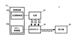
図1において、映像表示装置1は、制御装置10、光源20、MEMSミラー30及び表示面40を備えた、本発明に係る「表示装置」の一例である。映像表示装置1は、例えば、ヘッドマウントディスプレイ装置、ヘッドアップディスプレイ装置或いはプロジェクション表示装置等の投射型表示装置である。映像表示装置1では、光源20から照射される後述するレーザ光21R、21G、21Bが、MEMSミラー30において反射され、表示面40に投射されることによって映像が表示される。
In FIG. 1, the video display device 1 is an example of a “display device” according to the present invention that includes a
尚、映像表示装置1は、本発明に係る表示装置が採り得る実践的態様の一例であって、例えば、本発明に係る表示装置の実践的態様は、本発明に係る表示装置の概念を逸脱しない範囲で如何様にも変更され得る。 The video display device 1 is an example of a practical aspect that the display device according to the present invention can take. For example, the practical aspect of the display device according to the present invention deviates from the concept of the display device according to the present invention. It can be changed in any way within the range not to be.
制御装置10は、光源制御部100及びミラー制御部200並びにこれらの動作を統括的に制御するCPU(Central Processing Unit)、記憶装置としてのROM(Read Only Memory)及びRAM(Random Access Memory)等を備えた、本発明に係る「表示制御装置」の一例である。
The
制御装置10のROMには、光源制御部100及びミラー制御部200を駆動するための駆動制御プログラムが格納されている。この駆動制御プログラムは、本発明に係る「コンピュータプログラム」の一例である。また、ROMは、本発明に係る「記録媒体」の一例である。
The ROM of the
尚、ROMは不揮発性記憶装置であるから、本実施例において、駆動制御プログラムは予め制御部110に備わることになるが、この制御プログラムは、RAM若しくはハードディスク或いは制御装置10に備わり得る他の揮発性記憶装置に書き込まれていてもよい。この場合、駆動制御プログラムのアップデート及びメンテナンス等が比較的簡便になされ得る。また、この駆動制御プログラムをネットワークで配信する、或いは駆動制御プログラムが記録された記録媒体を配布する等の措置を講じることも可能となる。
Since the ROM is a non-volatile storage device, in this embodiment, the drive control program is provided in the control unit 110 in advance, but this control program is provided in the RAM, the hard disk, or other volatile data that can be provided in the
光源制御部100は、光源20の駆動状態を制御する制御ユニットである。光源制御部100の詳細な構成については、図2を参照して後述する。
The light
ミラー制御部200は、MEMSミラー30の駆動状態を制御する制御ユニットである。ミラー制御部200は、水平波形生成部、水平D/Aコンバータ、パワーアンプ、クロック生成部、垂直D/Aコンバータ及び垂直波形生成部等を備える。尚、ミラー制御部200の構成は、公知のMEMSミラーの制御装置を適用することができる。従って、ここではその詳細は省略する。ミラー制御部200は、例えば、下記の如くに動作する構成となっている。
The
水平波形生成部は、上述した水平走査方向にMEMSミラー30を掃引するための水平駆動信号を生成する。この水平波形生成部から供給される水平駆動信号は、水平D/AコンバータにおいてD/A変換され、パワーアンプにより増幅される。パワーアンプを通過した水平駆動信号はMEMSミラー30に供給され、この水平駆動信号によりMEMSミラー30は水平走査方向に駆動される。
The horizontal waveform generation unit generates a horizontal drive signal for sweeping the
垂直波形生成部は、上述した垂直走査方向にMEMSミラー30を掃引するための垂直駆動信号を生成する。この垂直波形生成部から供給される垂直駆動信号は、垂直D/AコンバータにおいてD/A変換され、パワーアンプにより増幅される。パワーアンプを通過した垂直駆動信号はMEMSミラー30に供給され、この垂直駆動信号によりMEMSミラー30は垂直走査方向に駆動される。
The vertical waveform generation unit generates a vertical drive signal for sweeping the
クロック生成部は、所定周期でクロック信号を生成可能に構成される。例えば、この所定周期は10ns程度に設定される。生成されたクロック信号は、垂直D/Aコンバータに供給される。尚、クロック生成部で生成された基本周期のクロック信号は、分周器により所望の周期のクロック信号に変換されてもよい。 The clock generation unit is configured to be able to generate a clock signal at a predetermined period. For example, this predetermined period is set to about 10 ns. The generated clock signal is supplied to the vertical D / A converter. Note that the clock signal having the basic cycle generated by the clock generation unit may be converted into a clock signal having a desired cycle by a frequency divider.
光源20は、赤、緑、青の各色に夫々対応する光源20R、20G及び20Bを含むレーザ光源であり、MEMSミラー30に対して赤、緑、青の各色に夫々対応するレーザ光21R、21G及び21Bを照射可能に構成されている。
The
MEMSミラー30は、各光源から照射されるレーザ光を反射して表示面40に投射するスキャニングミラーであり、本発明に係る「走査手段」の一例である。MEMSミラー30は、MEMS(微小電気機械システム)として構成されており、ミラー制御部200によりその動作状態が制御される構成となっている。
The
MEMSミラー30は、鏡面として機能するシリコン基板に、ピエゾ素子(圧電素子)によるピエゾ抵抗が形成された構成を有している。ピエゾ素子としては、圧電効果を有するものを広く使用可能であり、例えばPZT(チタン酸ジルコン酸鉛)等の圧電セラミクスを使用することができる。このピエゾ抵抗は、MEMSミラー30に印加される駆動電圧に応じて、その圧電効果により捩れを生じる。この捩れによりMEMSミラー30の鏡面の光源20に対する角度が変化する。即ち、所定の走査方向への走査が実現される。
The
一方、ピエゾ抵抗の電気抵抗値は、この捩れの度合いに応じて変化する。MEMSミラー30は、この電気抵抗値(即ち、捩れ角)に応じた電気信号をMEMS位置信号として取り出し可能に構成されている。尚、ピエゾ素子に生じる捩れの方向は、MEMSミラー30で反射する反射光(即ち、各光源のレーザ光)の走査方向であり、本実施例に係るMEMSミラー30は、垂直走査軸周りに生じる捩れに対応する垂直走査方向と、水平走査軸周りに生じる捩れに対応する水平走査方向との二つの走査方向に駆動される。
On the other hand, the electrical resistance value of the piezoresistor changes according to the degree of twist. The
MEMSミラー30は、垂直走査方向については鋸歯状波又は三角波である垂直駆動信号により駆動され、水平走査方向については正弦波である水平駆動信号により共振駆動される。尚、MEMSミラー30として例示される、本発明の走査手段に係る基本的構成や基本的駆動方法については公知である。従って、本実施例では、説明の煩雑化を防ぐ目的からその詳細についての説明を省略する。
The
表示面40は、MEMSミラー30により走査された各色のレーザ光が投射される、映像表示用のディスプレイ装置である。但し、表示面40は、直視型の表示装置と異なり、表示場所や表示エリアが予めハードウェア上の仕様として固定されない表示装置である。即ち、表示面40に表示される映像を構成する各画素の位置は、MEMSミラー30の動作によって実現し得る範囲で自由に定められ得る。
The
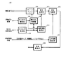
ここで、図2を参照し、光源制御部100の構成について説明する。ここに、図2は、光源制御部100のブロック図である。
Here, the configuration of the light
図2において、フレームバッファ101、補間処理部102、帯域制限部103、オフセット設定部104、読み出し制御部105、タイミング生成部106、補間情報生成部107、LPF強度設定部108及び光源駆動部109を備える。
In FIG. 2, a
フレームバッファ101は、映像信号入力端子(符号省略)から入力される、表示面40に投射すべき映像に関する、赤、緑、青の三色に対応する映像信号を蓄積可能に構成されたバッファである。
The
読み出し制御部105は、フレームバッファ101に蓄積された映像信号の中から複数画素分の映像信号を読み出し可能に構成されたプロセッサである。尚、映像信号が読み出される画素は、各色について相互に異なったものとすることができる。
The
補間処理部102は、補間中心の周辺に位置する各画素の映像信号に対し、表示面40上のレーザ光の走査位置に応じて設定される補間係数を乗じ、元々の映像信号にこれら補間用の映像信号を加算することによって補間処理を実行可能に構成されたプロセッサである。
The
補間情報生成部107は、上述した補間係数及び補間処理部102における補間位置を設定可能に構成されたプロセッサである。
The interpolation
尚、補間処理としては、例えば、バイリニア補間、バイキュービック補間、Bスプライン補間、Lanzos3補間等公知の各種補間処理が使用される。また、入力映像と出力映像との間で画素数やライン数が異なっている場合、即ち、解像度変換が必要となる場合には、その拡大率や縮小率を考慮した補間位置情報から補間係数が生成されてもよい。但し、本発明に係る表示制御装置の効果を説明する上では、この種の補間処理は必ずしも必要でない。 As the interpolation process, for example, various known interpolation processes such as bilinear interpolation, bicubic interpolation, B-spline interpolation, and Lanzos3 interpolation are used. In addition, when the number of pixels and the number of lines are different between the input video and the output video, that is, when resolution conversion is necessary, the interpolation coefficient is calculated from the interpolation position information considering the enlargement rate and reduction rate. May be generated. However, this type of interpolation processing is not necessarily required to explain the effect of the display control apparatus according to the present invention.
帯域制限部103は、補間処理部102から出力された映像信号に対し帯域制限処理を実行可能に構成された、本発明に係る「帯域制限手段」の一例たるディジタルLPF(ローパスフィルタ)である。尚、補間処理部102が、Bスプライン補間やLanzos3補間のように帯域制限特性を有する補間処理を行う構成を採る場合、補間処理と帯域制限処理とが併せて行われてもよい。帯域制限部103において帯域制限処理が施された映像信号は、光源駆動部109に入力される。
The
ここで、図3を参照し、帯域制限部103の構成について説明する。ここに、図3は、帯域制限部103のブロック図である。
Here, the configuration of the
図3において、帯域制限部103は、3タップのLPFであり、ラインメモリ1031及び1032、乗算器1033、1034及び1035並びに加算器1036から構成される。各ラインメモリは、水平走査方向一ライン分の画素信号(即ち、映像信号)を記憶するメモリである。乗算器1033、1034及び1035は、入力信号に夫々フィルタ係数a、b及びcを乗じる乗算器であり、フィルタ係数a、b、cの総和は1.0である。
In FIG. 3, the
図3において、乗算器1034に入力される画素信号Pbが、帯域制限処理の対象となる対象画素の映像信号であり、乗算器1033に入力される画素信号Paが対象画素の上の画素(即ち、対象画素よりも早い時間に信号入力された画素)の映像信号であり、乗算器1035に入力される画素信号Pcが対象画素の下の画素(即ち、対象画素よりも遅い時間に信号入力された画素)の映像信号である。尚、帯域制限処理が行われない場合、フィルタ係数bは1.0とされ、フィルタ係数a及びcは0.0とされる。
In FIG. 3, the pixel signal Pb input to the
尚、図示のLPFは3タップのLPFであるが、タップ数はより多くてもよい。例えば、帯域制限部103は、5タップのLPFであってもよい。この場合、3タップのLPFと較べて回路規模は大きくなるが、フィルタ特性の自由度がより拡大する。
Although the illustrated LPF is a 3-tap LPF, the number of taps may be larger. For example, the
図2に戻り、LPF強度設定部108は、帯域制限部103の上述したフィルタ係数a、b及びcを設定可能に構成された、本発明に係る「帯域制御手段」の一例たるプロセッサである。
Returning to FIG. 2, the LPF intensity setting unit 108 is a processor as an example of a “band control unit” according to the present invention configured to be able to set the above-described filter coefficients a, b, and c of the
光源駆動部109は、帯域制限部103から出力される映像信号に応じて、光源20に備わる赤、緑、青の各色の光源の特性に応じた電圧及び電流設定を行い、光源20を駆動する駆動信号を生成するプロセッサである。光源20は、この駆動信号により駆動制御される。光源駆動部109は、本発明に係る「駆動制御手段」の一例である。
The light
タイミング生成部106は、読み出し制御部105がフレームバッファ101から映像信号を読み出す読み出しタイミングや、補間情報生成部107における補間位置の決定に必要な補間タイミング等の各種タイミングを生成可能に構成されたプロセッサである。タイミング生成部106は、位置情報入力端子(符号省略)から、MEMSミラー30の位置(即ち、捩れ角)に関する上述したMEMS位置信号を受け取り、これらのタイミングを生成する構成となっている。
The
補足すると、光源20及びMEMSミラー30を含む投射型の映像表示装置1では、光源駆動部109から供給される駆動信号に対応する映像と、MEMSミラー30の水平走査方向及び垂直走査方向の捩れ角の位置関係が、2次元映像を表示面40に表示するために必要な関係になければならない。このため、タイミング生成部106では、入力されるMEMS位置信号に応じて各種のタイミングが生成される。例えば、上述した読み出し制御部105は、タイミング生成部106により生成される読み出しタイミングに従って、フレームバッファ101から映像信号を読み出すことができる。
Supplementally, in the projection-type image display device 1 including the
オフセット設定部104は、光路ズレ情報入力端子(符号省略)から入力される、後述する光路ズレ情報に基づいて、フレームバッファ101から映像信号を読み出す水平走査方向ラインのオフセット量を決定する。このオフセット量は、基準色に対する他色の相対的オフセット量である。尚、本実施例では、基準色は緑であるとする。
The offset
一方、光路ズレ情報は、上述したLPF強度設定部108にも入力される。LPF強度設定部108は、入力される光路ズレ情報に基づいて、帯域制限部103における帯域制限の度合いを決定し、帯域制限部103のフィルタ特性を制御する。尚、帯域制限の度合いは、上述したフィルタ係数a、b及びcにより決定される。
On the other hand, the optical path deviation information is also input to the above-described LPF intensity setting unit 108. The LPF intensity setting unit 108 determines the degree of band limitation in the
<実施例の動作>
次に、実施例の動作について説明する。
<Operation of Example>
Next, the operation of the embodiment will be described.
<MEMSミラー30の基本動作>
始めに、図4を参照し、MEMSミラー30の基本動作について説明する。ここに、図4は、投射面40に対するレーザ光の走査軌跡を説明する図である。
<Basic operation of
First, the basic operation of the
図4において、表示面40が格子状に表現されており、格子を構成する複数の矩形領域の一つ一つが画素Pである。尚、上述したように、投射型の表示装置において、表示面上の画素位置は表示面のハードウェア仕様として固定されていないため、実際には、各色に相当するレーザ光の集光位置が画素の位置である。
In FIG. 4, the
図4において、太い矢線で表現される軌跡が、光源20の基準色たる緑色に対応するレーザ光21Gの走査軌跡である。MEMSミラー30による光走査は、MEMSミラー30が、水平走査方向に共振駆動されることから、CRTやLCD等の一般的な表示モニタにおける光走査と異なり、所謂両側スキャン方式を採る。即ち、映像表示装置1において、レーザ光21Gは、往路(例えば、図中左側から右側)においても復路(例えば、図中右側から左側)においても走査される。
In FIG. 4, a locus represented by a thick arrow line is a scanning locus of the laser light 21 </ b> G corresponding to green as the reference color of the
次に、図5を参照して、表示面40上に生じる色ズレについて説明する。ここに、図5は、色ズレの概念図である。尚、同図において、図4と重複する箇所には同一の符号又は名称を付与してその説明を適宜省略することとする。
Next, with reference to FIG. 5, a color shift that occurs on the
図5において、光源20Gに対応するレーザ光21Gに加え、光源20Rに対応するレーザ光21Rの走査軌跡(破線矢線参照)が示される。図示の通り、これらの間には、垂直走査方向に1画素分の色ズレが生じている(図中白丸参照)。この色ズレは、例えば映像表示装置1の製造段階或いは組み付け段階等において生じる各レーザ光の光路のズレ(光路ズレ)によって生じる、一種の個体差である。尚、光路のズレとは、光軸のズレと言い換えてもよい。
In FIG. 5, in addition to the
ここで、レーザ光相互間の垂直走査方向の光路ズレの絶対値は、場合により数十画素分に達することもあるが、表示面40に投射される映像の品質に影響を与える、表示面上の色ズレは、両側スキャン方式を採用する映像表示装置1において最大で1画素である。それ以上の色ズレについては、上述したフレームバッファ101から映像信号を読み出す際に、垂直走査方向に画素単位で読み出しラインを画素単位でオフセットさせれば済むためである。例えば、垂直走査方向の光路ズレが20.5画素分生じている場合、20画素分だけ読み出しラインをオフセットさせれば、実際の色ズレは0.5画素分で済む。実施例に係る帯域制限部103による映像信号の帯域制限は、この最大1画素分生じる微小な色ズレによる映像品質の低下を抑制するものである。
Here, the absolute value of the optical path deviation in the vertical scanning direction between the laser beams may reach several tens of pixels depending on the case, but it affects the quality of the image projected on the
<帯域制限処理の効果>
次に、図6及び図7を参照し、帯域制限部103による帯域制限処理の効果について説明する。ここに、図6は、色ズレが生じた映像を例示する図であり、図7は、映像信号に帯域制限処理が施された図6の映像を例示する図である。
<Effect of bandwidth limitation processing>
Next, with reference to FIG. 6 and FIG. 7, the effect of the band limiting process by the
図6において、(a)は、色ズレが生じていない映像(即ち、本来表示されるべき元映像)である。これに対して(b)は、垂直走査方向にx(x<1)画素分の色ズレが生じた状態を例示する図であり、(c)は、垂直走査方向にy(x<y<1)画素分の色ズレが生じた状態を例示するである。尚、図6(b)及び図6(c)に例示される映像は、既に補間処理部102による補間処理がなされた状態を示している。
In FIG. 6, (a) is an image in which no color misregistration occurs (that is, an original image that should be displayed originally). On the other hand, (b) is a diagram illustrating a state in which a color shift of x (x <1) pixels occurs in the vertical scanning direction, and (c) is y (x <y <) in the vertical scanning direction. 1) This is an example of a state in which color misregistration for pixels has occurred. Note that the images illustrated in FIGS. 6B and 6C show a state where the interpolation processing by the
尚、先述したように、投射型の映像表示装置1では、各色のレーザ光の集光位置が画素の位置であるから、色ズレは、基準色に対する相対的な集光位置のズレとして定義することができる。ここで、一般的に緑は赤及び青と較べて輝度成分が大きいため、基準色として適当である。図6(b)、図6(c)は、例えば、緑と青との間に色ズレが無く(尚、上述したように、この場合にも光路ズレは必ずしもゼロでない)、緑と赤との間に上記x又はy画素分の色ズレが生じている状態を示している。図示の通り、色ズレが大きい程、映像の品質は低下する。 Note that, as described above, in the projection-type image display device 1, since the condensing position of the laser light of each color is the pixel position, the color misregistration is defined as a deviation of the condensing position relative to the reference color. be able to. Here, since green generally has a larger luminance component than red and blue, it is suitable as a reference color. 6B and 6C show, for example, that there is no color misalignment between green and blue (note that the optical path misalignment is not always zero in this case as well), and green and red A state in which the color misregistration corresponding to the x or y pixels is generated during the period is shown. As shown in the figure, the larger the color deviation, the lower the quality of the video.
図7には、図6に例示される各映像に関する映像信号に対し、帯域制限部103による帯域制限処理が講じられた状態が示される。尚、色ズレの生じていない映像に対応する図6(a)と図7(a)とは同じである。
FIG. 7 shows a state in which the band limiting process by the
図7(b)及び図7(c)は、いずれも映像信号に帯域制限処理が施された映像を示すが、x(x<1)画素分の色ズレが生じた映像に対応する図7(b)よりも、y(x<y<1)画素分の色ズレが生じた映像に対応する図7(c)の方が、帯域制限の度合いが大きい。即ち、図7(c)に例示される映像は、図7(b)に例示される映像と較べて、映像の境界部分の解像度が低下しており、視覚的によりぼかしの掛かった状態となっている。 FIG. 7B and FIG. 7C both show an image obtained by subjecting the video signal to band limitation processing, and FIG. 7 corresponds to an image in which a color shift of x (x <1) pixels has occurred. FIG. 7C corresponding to an image in which color misregistration corresponding to y (x <y <1) pixels has occurred has a greater degree of band limitation than (b). That is, the image illustrated in FIG. 7C has a lower resolution at the boundary portion of the image than the image illustrated in FIG. 7B, and is visually blurred. ing.
このように、本実施例では、色ズレの大小、即ち光路ズレ量の大小に基づいて帯域制限の度合いが制御される。このように、相対的に大きい色ズレに対して相対的に帯域制限の度合を大きくすることによって、色ズレが映像に与える影響を緩和することができる。即ち、本実施例によれば、色ズレによる映像品質の低下が好適に抑制される。 Thus, in the present embodiment, the degree of band limitation is controlled based on the magnitude of color misregistration, that is, the magnitude of the optical path misregistration amount. Thus, by increasing the degree of band limitation relative to a relatively large color shift, the influence of the color shift on the video can be mitigated. That is, according to the present embodiment, the deterioration of the video quality due to the color shift is preferably suppressed.
また、色ズレの影響を緩和することのみを考えた場合、帯域制限の度合いは大きい方がよいが、図示の通り、帯域制限の度合いを大きくすると、映像の解像度が低下して、別の意味で映像の品質の低下が生じ得る。そこで、色ズレの度合いに応じて帯域制限の度合いを変化させることにより、映像品質の低下が好適に抑制されるのである。 In addition, when considering only the effect of color misregistration, the degree of band limitation is better, but as shown in the figure, increasing the band limitation degree lowers the resolution of the video and has another meaning. In this case, the quality of the image may be degraded. Therefore, a reduction in video quality is suitably suppressed by changing the band restriction degree according to the degree of color misregistration.
<帯域制限部103の動作>
次に、図8を参照し、帯域制限部103のフィルタ特性について説明する。ここに、図8は、帯域制限部103におけるフィルタ係数とフィルタ特性との関係を例示する図である。
<Operation of
Next, the filter characteristics of the
図8において、縦軸は信号通過量(dB)であり、横軸は周波数指標値である。周波数指標値は、サンプリング周波数の1/2の周波数を1.0として規格化した値である。即ち、サンプリング定理から、周波数指標値が1.0のポイントは、表示すべき映像の最大周波数に相当する。 In FIG. 8, the vertical axis represents the signal passing amount (dB), and the horizontal axis represents the frequency index value. The frequency index value is a value that is normalized with a half of the sampling frequency as 1.0. That is, from the sampling theorem, the point where the frequency index value is 1.0 corresponds to the maximum frequency of the video to be displayed.
図8(a)は、フィルタ係数b=0.875、a=c=0.0625の場合のフィルタ特性を例示する。このフィルタ特性では、全周波数域で50%(−3.0dB)以上の通過量が確保される。即ち、図8(a)は、帯域制限の度合いが小さい場合のフィルタ特性に対応する。 FIG. 8A illustrates filter characteristics when the filter coefficient b = 0.875 and a = c = 0.0625. With this filter characteristic, a passing amount of 50% (−3.0 dB) or more is ensured in the entire frequency range. That is, FIG. 8A corresponds to the filter characteristic when the degree of band limitation is small.
図8(b)は、フィルタ係数b=0.750、a=c=0.125の場合のフィルタ特性を例示する。このフィルタ特性では、周波数指標値0.6付近にカットオフ周波数が設定されており、中高周波帯域が制限される。 FIG. 8B illustrates filter characteristics when the filter coefficient b = 0.750 and a = c = 0.125. In this filter characteristic, the cut-off frequency is set near the frequency index value 0.6, and the mid-high frequency band is limited.
図8(c)は、フィルタ係数b=0.500、a=c=0.250の場合のフィルタ特性を例示する。このフィルタ特性では、周波数指標値0.35付近にカットオフ周波数が設定されており、中高周波帯域が大きく制限される。即ち、図8(c)は、帯域制限の度合いが大きい場合のフィルタ特性に対応する。また、図8(a)及び図8(c)との対比の上では、図8(b)は、帯域制限の度合いが中程度のフィルタ特性に対応すると言える。 FIG. 8C illustrates filter characteristics when the filter coefficient b = 0.500 and a = c = 0.250. In this filter characteristic, the cut-off frequency is set in the vicinity of the frequency index value 0.35, and the mid-high frequency band is greatly limited. That is, FIG. 8C corresponds to the filter characteristic when the degree of band limitation is large. Further, in comparison with FIGS. 8A and 8C, it can be said that FIG. 8B corresponds to a filter characteristic with a medium degree of band limitation.
このように、帯域制限部103では、LPF強度設定部108が設定するフィルタ係数a、b及びcにより、映像信号の帯域制限の度合いを変化させることができる。従って、図7に例示された如き、色ズレの度合いに応じた帯域制限処理が可能となるのである。
As described above, the
<LPF強度設定部108の動作>
次に、LPF強度設定部108の動作について説明する。
<Operation of LPF Strength Setting Unit 108>
Next, the operation of the LPF intensity setting unit 108 will be described.
始めに、MEMSミラー30が静止しており、MEMSミラー30と被投射面たる表示面40とが正対している状態における、レーザ光21R、21G、21Bの各光の垂直走査方向の位置を、夫々POSv_R、POSv_G、POSv_Bとする。
First, the position in the vertical scanning direction of each of the
次に、基準色たるレーザ光21Gの光束の中心位置からレーザ光21Rの光束の中心位置までの距離を、暫定光路ズレ量POSvd_Rtmp、レーザ光21Gの光束の中心位置からレーザ光21Bの光束の中心位置までの距離を暫定光路ズレ量POSvd_Btmpとすると、下記(1)及び(2)式が成立する。
Next, the distance from the center position of the
POSvd_Rtmp=POSv_R−POSv_G・・・(1)
POSvd_Btmp=POSv_B−POSv_G・・・(2)
例えば、MEMSミラー30の映像表示能力が、水平走査方向に1280画素、垂直走査方向に720ライン(720画素分のライン)である場合において、
POSv_G=360.0
POSv_R=363.0
POSv_B=365.9
であった場合、
POSvd_Rtmp=3.0
POSvd_Btmp=5.9
となる。
POSvd_Rtmp = POSv_R-POSv_G (1)
POSvd_Btmp = POSv_B-POSv_G (2)
For example, when the image display capability of the
POSv_G = 360.0
POSv_R = 363.0
POSv_B = 365.9
If
POSvd_Rtmp = 3.0
POSvd_Btmp = 5.9
It becomes.
ここで、暫定光路ズレ量と表現するのは、先述したように、両側スキャン方式を採用する映像表示装置1において、各レーザ光の光路ズレの最大値は1画素となるからである。即ち、例えば、1.9画素分、垂直走査方向上側に生じた光路ズレは、0.1画素分、垂直走査方向下側に生じた光路ズレと等しく扱うことができるのである。この点を考慮して、最終的な光路ズレ量を定義すると、レーザ光21Gとレーザ光21Rとの間の光路ズレ量POSvd_R、レーザ光21Gとレーザ光21Bとの間の光路ズレ量POSvd_Bは、夫々下記(3)及び(4)式により表される。
Here, the provisional optical path deviation amount is expressed because, as described above, in the video display apparatus 1 that employs the double-sided scanning method, the maximum value of the optical path deviation of each laser beam is one pixel. That is, for example, an optical path shift that occurs on the upper side in the vertical scanning direction by 1.9 pixels can be treated equally with an optical path shift that occurs on the lower side in the vertical scanning direction by 0.1 pixel. Considering this point, when the final optical path deviation amount is defined, the optical path deviation amount POSvd_R between the
POSvd_R=ABS(ABS(POSv_R−POSv_G)−2n)…(3)
POSvd_B=ABS(ABS(POSv_B−POSv_G)−2n)…(4)
ここで、ABSは絶対値を表し、nは各値を最小とし得る自然数又はゼロである。
POSvd_R = ABS (ABS (POSv_R-POSv_G) -2n) (3)
POSvd_B = ABS (ABS (POSv_B-POSv_G) -2n) (4)
Here, ABS represents an absolute value, and n is a natural number that can minimize each value or zero.
LPF強度設定部108は、上記(3)及び(4)式により定義される光路ズレ量に基づいて、帯域制限部103における帯域制限の度合いを決定する。具体的には、上述したフィルタ係数a、b、cを決定する。
The LPF intensity setting unit 108 determines the degree of band limitation in the
尚、光路ズレ量に基づいたフィルタ係数の決定方法は、光路ズレ量の大小がフィルタ係数bの小大及びフィルタ係数a、cの大小に夫々対応する(言い換えれば、光路ズレ量の大小が帯域制限の度合いの大小に対応する)限りにおいて限定されない。 Note that the filter coefficient determination method based on the optical path deviation amount corresponds to the magnitude of the optical path deviation quantity corresponding to the magnitude of the filter coefficient b and the magnitudes of the filter coefficients a and c (in other words, the magnitude of the optical path deviation quantity corresponds to the band). It is not limited as long as it corresponds to the degree of restriction.
例えば、帯域制限部103におけるカットオフ周波数の最大値及び最小値を決定しておき、光路ズレ量を複数段階に分割して、光路ズレ量の大小がカットオフ周波数の低高に夫々対応するように、分割された段階に応じてカットオフ周波数が割り当てられていてもよい。尚、カットオフ周波数の最高値とは、好適には帯域制限無し(フィルタ係数b=1.0)の場合のカットオフ周波数である。
For example, the maximum value and the minimum value of the cutoff frequency in the
ところで、基準光であるレーザ光21Gに対する相対的ズレ量として光路ズレ量を定義すると、光路ズレ量は、レーザ光21Rに対応する値と、レーザ光21Bに対応する値との二種類決定される。これらの光路ズレ量に相関はないから、双方を効果的に抑制する帯域制限処理を施すことは難しい。そこで、LPF強度設定部108は、二つの光路ズレ量に対して重み付けを付与すると共に、当該付与された重み付けを考慮して最終的なフィルタ係数を決定する構成となっている。
By the way, when the optical path deviation amount is defined as a relative deviation amount with respect to the
ここで、最も単純且つ有効な重み付けの付与態様の一つは、基準光以外の他色光のうち一方に帯域制限の度合いを整合させることである。即ち、この場合、一方に付与される重みが100%、他方に付与される重みが0%に相当する。ここで特に、赤と青とを較べた場合、レーザ光21Bの輝度成分は、レーザ光21Rと較べて小さい。即ち、赤色の色ズレの方が、青色の色ズレよりも目立ち易い。従って、この場合、レーザ光21Rの光路ズレ量たるPOSvd_Rに基づいてフィルタ係数を決定することができる。
Here, one of the simplest and most effective weighting modes is to match the band limitation degree to one of the other color lights other than the reference light. That is, in this case, the weight given to one side corresponds to 100% and the weight given to the other corresponds to 0%. Here, in particular, when comparing red and blue, the luminance component of the laser beam 21B is smaller than that of the
一般的には、重み係数をk(0<k<1)とすると、下記(5)式のようにフィルタ係数決定用の光路ズレ量POSvd’を定義することもできる。 In general, when the weighting coefficient is k (0 <k <1), the optical path deviation amount POSvd ′ for determining the filter coefficient can be defined as in the following equation (5).
POSvd’=POSvd_R×k+POSvd_B×(1−k)・・・(5)
尚、LPF強度設定部108が帯域制限の度合い(本実施例ではフィルタ係数と一義的な関係にある)を決定するにあたって参照する上述の光路ズレ量は、上述したように、予め光路ズレ情報として光路ズレ情報入力端子から入力される。
POSvd ′ = POSvd_R × k + POSvd_B × (1-k) (5)
Note that the optical path deviation amount referred to when the LPF intensity setting unit 108 determines the degree of band limitation (which is uniquely related to the filter coefficient in this embodiment) is the optical path deviation information in advance as described above. Input from the optical path deviation information input terminal.
ここで、光源20の光路ズレが製造段階或いは組み付け段階で生じ得る性質のものである点に鑑みれば、光路ズレ情報は、映像表示装置1の初期設定情報として与えておくこともできる。一方で、上述した暫定光路ズレ量が、MEMSミラー30と表示面40とが正対関係にある場合の集光位置のズレ量に起因する点に鑑みれば、動作条件や動作環境が変化する毎に、暫定光路ズレ量の計測が行われ、光路ズレ情報が適宜更新される構成とされてもよい。このようにすれば、温度変化や経時変化による光路ズレ量の変化に適応することが容易にして可能となる。尚、この場合、映像表示装置1が暫定光路ズレ量の計測手段を備える必要があるが、この種の計測手段は例えばフォトディテクタ等を利用した公知の計測手段を好適に適用することができる。
Here, in view of the fact that the optical path deviation of the
<第2実施例>
第1実施例では、帯域制限部103の帯域制限の度合いに対応するフィルタ係数が、LPF強度設定部111により、上述した光路ズレ情報に基づいて決定された。しかしながら、表示面40に生じる色ズレそのものを調整せずに映像の品質低下を抑制する技術思想を有する本発明の表示制御装置の概念においては、光路ズレ情報以外にも、帯域制限の度合いを決定するにあたっての参照要素が存在し得る。このような趣旨に沿った本発明の第2実施例について、図9を参照して説明する。ここに、図9は、第2実施例に係る光源制御部110のブロック図である。尚、同図において、図2と重複する箇所には同一の符号を付してその説明を適宜省略することとする。
<Second embodiment>
In the first embodiment, the filter coefficient corresponding to the degree of band limitation of the
図9において、光源制御部110は、LPF強度設定部108に替えて、LPF強度設定部111を備える点において、第1実施例に係る光源制御部100と相違する。
In FIG. 9, the light source control unit 110 is different from the light
LPF強度設定部111は、帯域制御情報入力端子(符号省略)から入力される帯域制御情報に基づいて帯域制限部103における帯域制限の度合い(即ち、フィルタ係数)を決定する構成となっている。
The LPF intensity setting unit 111 is configured to determine the degree of band limitation (that is, the filter coefficient) in the
ここで、帯域制御情報入力端子から入力される帯域制御情報としては、投射面サイズ、視距離、アスペクト比等を使用することができる。 Here, as the band control information input from the band control information input terminal, a projection plane size, a viewing distance, an aspect ratio, and the like can be used.
<投射面サイズに応じた帯域制限処理>
各レーザ光の投射面である表示面40の画面サイズが大きければ、その分、色ズレは目立つ。従って、表示面40の画面サイズの大小に応じて、帯域制限の度合いを夫々大小に制御することによって、色ズレによる映像品質の低下を好適に抑制することができる。
<Band limitation processing according to the projection surface size>
If the screen size of the
尚、映像表示装置1において表示面40の構成が変化することは殆どないから、この場合の帯域制御情報(画面サイズ)は、予め初期設定情報として与えておくことができる。即ち、この場合、基準となる画面サイズに対する帯域制限の度合い(即ち、基準の度合い)が定められており、表示面40と当該基準となる画面サイズとの大小関係に応じて、この基準の度合いが大小に補正されてもよい。
Since the configuration of the
<視距離に応じた帯域制限処理>
視距離とは、映像表示装置1を利用する利用者と表示面40との物理的な距離である。視距離が短ければ、その分だけ利用者は映像を精細に認識することができる。必然的に、視距離が短ければ色ズレが目立つことになる。
<Band limit processing according to viewing distance>
The viewing distance is a physical distance between the user who uses the video display device 1 and the
従って、視距離の大小に応じて、帯域制限の度合いを夫々小大に制御することによって、色ズレによる映像品質の低下を好適に抑制することができる。 Therefore, by controlling the degree of band limitation to a small or large size according to the viewing distance, it is possible to suitably suppress a decrease in video quality due to color shift.
尚、映像表示装置1と利用者との距離たる視距離は、その都度利用環境に応じて変化し得る。従って、この場合、視距離を外部から参照情報として入力する構成とされてもよい。また、視距離を計測する手段を設け、初期設定として計測された視距離を帯域制御情報として入力する構成とされてもよい。 Note that the viewing distance, which is the distance between the video display device 1 and the user, can change according to the usage environment each time. Therefore, in this case, the viewing distance may be input as reference information from the outside. Further, a means for measuring the viewing distance may be provided, and the viewing distance measured as the initial setting may be input as band control information.
尚、この場合、基準となる視距離に対する帯域制限の度合い(即ち、基準の度合い)が定められており、実際の視距離に応じて、この基準の度合いが大小に補正されてもよい。 In this case, the degree of band limitation (that is, the degree of reference) with respect to the reference viewing distance is determined, and this reference degree may be corrected to be large or small according to the actual viewing distance.
<アスペクト比に応じた帯域制限処理>
MEMSミラー30においては、垂直走査位置(捩れ角)と水平走査位置(捩れ角)とを独立して制御することができる。従って、元映像に対してアスペクト比を異ならしめた映像を表示面40に投射することが容易にして可能である。
<Bandwidth limit processing according to aspect ratio>
In the
ここで、アスペクト比の変更に伴って映像が相対的に垂直走査方向に拡大された場合、例えば、16:9のアスペクト比が16:18に変更された場合、表示面40の画面サイズが例え小さくとも、垂直走査方向に生じる色ズレは相対的に目立つ結果となる。反対に、アスペクト比の変更に伴って映像が相対的に垂直走査方向に縮小された場合、例えば、16:9のアスペクト比が16:4に変更された場合、表示面40の画面サイズが例え大きくとも、垂直走査方向に生じる色ズレは相対的に目立たない結果となる。
Here, when the image is relatively enlarged in the vertical scanning direction with the change in the aspect ratio, for example, when the aspect ratio of 16: 9 is changed to 16:18, the screen size of the
従って、表示面40のアスペクト比に応じて帯域制限の度合いを制御することによって、色ズレによる映像品質の低下を好適に抑制することができる。
Therefore, by controlling the degree of band limitation in accordance with the aspect ratio of the
<第3実施例>
第2実施例と同様の趣旨に基づいた第3実施例について、図10を参照して説明する。ここに、図10は、第3実施例に係る光源制御部120のブロック図である。尚、同図において、図2と重複する箇所には同一の符号を付してその説明を適宜省略することとする。
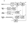
<Third embodiment>
A third embodiment based on the same purpose as the second embodiment will be described with reference to FIG. FIG. 10 is a block diagram of the light
図10において、光源制御部120は、映像解析部121を備え、またLPF強度設定部108に替えてLPF強度設定部122を備える点において、第1実施例に係る光源制御部100と相違する。
In FIG. 10, the light
映像解析部121は、映像信号入力端子から入力される映像信号に基づいて、映像の空間周波数を解析するプロセッサである。LPF強度設定部122は、映像解析部121により解析された空間周波数に基づいて帯域制限部103における帯域制限の度合い(即ち、フィルタ係数)を制御する。
The video analysis unit 121 is a processor that analyzes the spatial frequency of video based on the video signal input from the video signal input terminal. The LPF
表示面40における色ズレは、投射される映像における色の境界部分、特に白と黒との境界部分において目立ち易い。また、赤、緑、青の三原色の輝度成分の高い画素と低い画素との境界においても、色ズレは目立ち易い。
The color shift on the
ここで、このような色ズレの相対的に目立つ境界部分では、映像の空間周波数が高くなる。従って、空間周波数の高低に応じて帯域制限の度合いを夫々大小に制御することによって、色ズレによる映像品質の低下を好適に抑制することができる。 Here, the spatial frequency of the image is high at the boundary portion where such color misalignment is relatively conspicuous. Therefore, by controlling the degree of band limitation according to the level of the spatial frequency, it is possible to suitably suppress the deterioration of the video quality due to the color shift.
尚、空間周波数を解析する方法については公知の各種手法を適用可能である。例えば、映像解析部121は、垂直走査方向において対象画素と隣接する周辺画素について、映像信号を一次微分処理し、その絶対値に基づいて空間周波数の強度を算出してもよい。 Various known methods can be applied to the method of analyzing the spatial frequency. For example, the video analysis unit 121 may perform first-order differential processing on the video signal for peripheral pixels adjacent to the target pixel in the vertical scanning direction, and calculate the intensity of the spatial frequency based on the absolute value.
<第4実施例>
次に、第2及び第3実施例と同様の趣旨に基づいた第4実施例について、図11を参照して説明する。ここに、図11は、第4実施例に係る光源制御部130のブロック図である。尚、同図において、図2と重複する箇所には同一の符号を付してその説明を適宜省略することとする。
<Fourth embodiment>
Next, a fourth embodiment based on the same purpose as the second and third embodiments will be described with reference to FIG. FIG. 11 is a block diagram of the light
図10において、光源制御部130は、投射距離計測部131を備え、またLPF強度設定部108に替えてLPF強度設定部132を備える点において、第1実施例に係る光源制御部100と相違する。
In FIG. 10, the light
投射距離計測部131は、帯域制御情報入力端子(符号省略)から入力される、帯域制御情報としての投射角又は最大捩れ角に基づいて、MEMSミラー30から表示面40までのレーザ光の投射距離を計測するプロセッサである。LPF強度設定部132は、投射距離計測部131により計測された投射距離に基づいて帯域制限部103における帯域制限の度合い(即ち、フィルタ係数)を制御する。
The projection
本実施例における投射距離とは、MEMSミラー30から表示面40までの距離である。投射距離が変化すると、表示面40における色ズレの規模も変化する。具体的には、投射距離が大きくなると、色ズレの規模も大きくなる。
The projection distance in the present embodiment is a distance from the
ところで、第1実施例において(3)式及び(4)式を参照して説明した光路ズレ量は、MEMSミラー30と表示面40とが正対している状態を前提としている。しかしながら、実際には、MEMSミラー30は、レーザ光の走査過程で水平走査方向の捩れ角θhや垂直走査方向の捩れ角θvが変化する。
By the way, the optical path shift amount described with reference to the equations (3) and (4) in the first embodiment is based on the premise that the
これら捩れ角が0°〜90°の範囲においては、捩れ角が増大する程、MEMSミラー30から表示面40までの距離(投射距離)が大きくなり、結果として色ズレも大きくなる。このような問題は、システム側で糸巻き補正等の補正措置が講じられたとしても、基本的には変わらずに生じ得る。また、投射距離と色ズレとの関係は、表示面40に対してレーザ光が斜め方向から投射された場合も同様に生じ得る。
When the twist angle is in the range of 0 ° to 90 °, the distance from the
そこで、本実施例では、帯域制御情報としてMEMSミラー30の投射角や最大捩れ角の情報が入力され、これらの情報を基に投射距離計測部131において投射距離が計測或いは算出される。また、帯域制限部103のフィルタ係数は、計測或いは算出された投射距離に基づいて決定される。尚、この帯域制御情報としての投射角はMEMSミラー30の駆動制御量としてミラー制御部200が把握している。また、最大捩れ角は、MEMSミラー30に固有の値である。
Therefore, in this embodiment, information on the projection angle and the maximum twist angle of the
従って、本実施例によれば、投射距離に起因して生じる色ズレによる映像品質の低下を好適に抑制することができる。 Therefore, according to the present embodiment, it is possible to suitably suppress the deterioration of the video quality due to the color shift caused by the projection distance.
本発明は、上述した実施例に限られるものではなく、請求の範囲及び明細書全体から読み取れる発明の要旨或いは思想に反しない範囲で適宜変更可能であり、そのような変更を伴う表示制御装置もまた本発明の技術的範囲に含まれるものである。 The present invention is not limited to the above-described embodiments, and can be appropriately changed without departing from the gist or concept of the invention that can be read from the claims and the entire specification. A display control apparatus with such a change is also applicable. Moreover, it is included in the technical scope of the present invention.
1…映像表示装置、10…制御装置、20…光源、30…MEMSミラー、40…表示免、100…光源制御部、103…帯域制限部、108…LPF強度設定部108、200…ミラー制御部。
DESCRIPTION OF SYMBOLS 1 ... Video display apparatus, 10 ... Control apparatus, 20 ... Light source, 30 ... MEMS mirror, 40 ... Display exemption, 100 ... Light source control part, 103 ... Band-limiting part, 108 ... LPF
Claims (10)
前記被投射面に表示すべき映像に関する映像信号の帯域制限を行う帯域制限手段と、
前記帯域制限がなされた映像信号に基づいて前記光源の駆動状態を制御する駆動制御手段と
を備える表示制御装置。 A display control device that controls a display device including a plurality of light sources and a scanning unit that scans irradiation light emitted from the plurality of light sources on a projection surface,
Band limiting means for limiting the band of the video signal related to the video to be displayed on the projection surface;
And a drive control means for controlling the drive state of the light source based on the video signal subjected to the band limitation.
ことを特徴とする請求項1に記載の表示制御装置。 The display control apparatus according to claim 1, further comprising band control means for controlling the degree of band limitation based on a shift amount of an optical path between the plurality of light sources on the projection surface.
前記光路のズレ量は、前記垂直走査方向における光路のズレ量である
ことを特徴とする請求項2に記載の表示制御装置。 Each of the plurality of irradiation lights is scanned in the vertical scanning direction and the horizontal scanning direction on the projection surface,
The display control apparatus according to claim 2, wherein the amount of deviation of the optical path is an amount of deviation of the optical path in the vertical scanning direction.
前記光路のズレ量は、基準となる光源の照射光に対する他の光源の照射光の光路のズレ量として定義され、
前記帯域制御手段は、前記光路のズレ量に相対的重み付けを付与すると共に、該付与された重み付けを考慮して前記帯域制限の度合いを制御する
ことを特徴とする請求項2又は3に記載の表示制御装置。 The display device includes at least three or more light sources,
The amount of deviation of the optical path is defined as the amount of deviation of the optical path of the irradiation light of another light source with respect to the irradiation light of the reference light source,
4. The band control unit according to claim 2 or 3, wherein the band control unit gives a relative weight to the amount of deviation of the optical path and controls the degree of the band limitation in consideration of the given weight. Display control device.
ことを特徴とする請求項1に記載の表示制御装置。 The band control means includes at least one of a spatial frequency of the video, a viewing distance of the video, a size of the video on the projection surface, an aspect ratio of the video on the projection surface, and a projection distance of the video. The display control apparatus according to claim 1, wherein the degree of band limitation is determined based on the following.
ことを特徴とする請求項1から5のいずれか一項に記載の表示制御装置。 The display controller according to any one of claims 1 to 5, wherein the light source is a laser or an LED.
ことを特徴とする請求項1から6のいずれか一項に記載の表示制御装置。 The display control apparatus according to claim 1, wherein the scanning unit is a MEMS mirror.
前記被投射面に表示すべき映像に関する映像信号の帯域制限を行う帯域制限工程と、
前記帯域制限がなされた映像信号に基づいて前記光源の駆動状態を制御する駆動制御工程と
を備える映像表示方法。 A display control method in a display device comprising: a plurality of light sources; and a scanning unit that scans each of the irradiation lights emitted from the plurality of light sources on a projection surface,
A band limiting step of limiting the band of the video signal related to the video to be displayed on the projection surface;
And a drive control step of controlling a drive state of the light source based on the video signal subjected to the band limitation.
ことを特徴とするコンピュータプログラム。 A computer program for causing a computer system to function as the display control device according to any one of claims 1 to 7.
ことを特徴とする記録媒体。 A recording medium on which the computer program according to claim 9 is recorded.
Priority Applications (1)
| Application Number | Priority Date | Filing Date | Title |
|---|---|---|---|
| JP2013141106A JP2015014691A (en) | 2013-07-04 | 2013-07-04 | Display controller |
Applications Claiming Priority (1)
| Application Number | Priority Date | Filing Date | Title |
|---|---|---|---|
| JP2013141106A JP2015014691A (en) | 2013-07-04 | 2013-07-04 | Display controller |
Related Child Applications (1)
| Application Number | Title | Priority Date | Filing Date |
|---|---|---|---|
| JP2018037736A Division JP2018101151A (en) | 2018-03-02 | 2018-03-02 | Display control device |
Publications (1)
| Publication Number | Publication Date |
|---|---|
| JP2015014691A true JP2015014691A (en) | 2015-01-22 |
Family
ID=52436443
Family Applications (1)
| Application Number | Title | Priority Date | Filing Date |
|---|---|---|---|
| JP2013141106A Pending JP2015014691A (en) | 2013-07-04 | 2013-07-04 | Display controller |
Country Status (1)
| Country | Link |
|---|---|
| JP (1) | JP2015014691A (en) |
Cited By (6)
| Publication number | Priority date | Publication date | Assignee | Title |
|---|---|---|---|---|
| JP2017122708A (en) * | 2015-10-21 | 2017-07-13 | セミコンダクター・コンポーネンツ・インダストリーズ・リミテッド・ライアビリティ・カンパニー | Method of forming transducer controller and circuit for the same |
| EP3246872A1 (en) * | 2016-05-20 | 2017-11-22 | Canon Kabushiki Kaisha | Image processing apparatus, image processing method, and program |
| JP2019503079A (en) * | 2016-01-11 | 2019-01-31 | フィスバ・アクチェンゲゼルシャフトFisba Ag | Optical module manufacturing method, optical module, optical module operating method, and computer program product |
| JP2020094891A (en) * | 2018-12-12 | 2020-06-18 | コニカミノルタ株式会社 | Image inspection device and image inspection method |
| JP2021001893A (en) * | 2015-10-21 | 2021-01-07 | セミコンダクター・コンポーネンツ・インダストリーズ・リミテッド・ライアビリティ・カンパニー | Method for forming transducer controller and circuit therefor |
| WO2022025012A1 (en) * | 2020-07-31 | 2022-02-03 | 富士フイルム株式会社 | Optical scanning device, method for driving same, and image drawing system |
Citations (3)
| Publication number | Priority date | Publication date | Assignee | Title |
|---|---|---|---|---|
| JP2007057599A (en) * | 2005-08-22 | 2007-03-08 | Sony Corp | Image signal processing apparatus, image signal processing method and image signal processing system |
| JP2009044488A (en) * | 2007-08-09 | 2009-02-26 | Sony Corp | Projector and video signal processing method |
| JP2012145755A (en) * | 2011-01-12 | 2012-08-02 | Konica Minolta Advanced Layers Inc | Image display device |
-
2013
- 2013-07-04 JP JP2013141106A patent/JP2015014691A/en active Pending
Patent Citations (3)
| Publication number | Priority date | Publication date | Assignee | Title |
|---|---|---|---|---|
| JP2007057599A (en) * | 2005-08-22 | 2007-03-08 | Sony Corp | Image signal processing apparatus, image signal processing method and image signal processing system |
| JP2009044488A (en) * | 2007-08-09 | 2009-02-26 | Sony Corp | Projector and video signal processing method |
| JP2012145755A (en) * | 2011-01-12 | 2012-08-02 | Konica Minolta Advanced Layers Inc | Image display device |
Cited By (7)
| Publication number | Priority date | Publication date | Assignee | Title |
|---|---|---|---|---|
| JP2017122708A (en) * | 2015-10-21 | 2017-07-13 | セミコンダクター・コンポーネンツ・インダストリーズ・リミテッド・ライアビリティ・カンパニー | Method of forming transducer controller and circuit for the same |
| JP2021001893A (en) * | 2015-10-21 | 2021-01-07 | セミコンダクター・コンポーネンツ・インダストリーズ・リミテッド・ライアビリティ・カンパニー | Method for forming transducer controller and circuit therefor |
| JP2019503079A (en) * | 2016-01-11 | 2019-01-31 | フィスバ・アクチェンゲゼルシャフトFisba Ag | Optical module manufacturing method, optical module, optical module operating method, and computer program product |
| EP3246872A1 (en) * | 2016-05-20 | 2017-11-22 | Canon Kabushiki Kaisha | Image processing apparatus, image processing method, and program |
| US9967528B2 (en) | 2016-05-20 | 2018-05-08 | Canon Kabushiki Kaisha | Image processing apparatus and image processing method |
| JP2020094891A (en) * | 2018-12-12 | 2020-06-18 | コニカミノルタ株式会社 | Image inspection device and image inspection method |
| WO2022025012A1 (en) * | 2020-07-31 | 2022-02-03 | 富士フイルム株式会社 | Optical scanning device, method for driving same, and image drawing system |
Similar Documents
| Publication | Publication Date | Title |
|---|---|---|
| JP2015014691A (en) | Display controller | |
| JP5318359B2 (en) | Image projection device | |
| JP4777675B2 (en) | Image processing apparatus, image display apparatus, image processing method, program for causing computer to execute the method, and recording medium | |
| JP4639973B2 (en) | Image projection device | |
| WO2010021215A1 (en) | Image projection device | |
| JP7062952B2 (en) | Projection devices, projection modules and electronic devices | |
| JP6172773B2 (en) | Projector and image display method | |
| CN105247601B (en) | Display device | |
| JP5323272B2 (en) | LIGHT EMITTING CONTROL DEVICE AND METHOD, LIGHT EMITTING DEVICE, IMAGE DISPLAY DEVICE, PROGRAM, AND RECORDING MEDIUM | |
| JP5744586B2 (en) | Liquid crystal display device and program used therefor | |
| JP6613984B2 (en) | Drawing apparatus and drawing method | |
| KR20070120747A (en) | Display apparatus using laser | |
| JP6471438B2 (en) | Output control device, output control system, and output control program | |
| JP2012118186A (en) | Display device | |
| JP5358970B2 (en) | Image display apparatus using laser light source and image display method thereof | |
| JP2013025141A (en) | Image processor, image display device and image processing method | |
| JP2018101151A (en) | Display control device | |
| JP6391280B2 (en) | Image display apparatus and control method thereof | |
| JP2009058676A (en) | Image forming apparatus | |
| JP2010139687A (en) | Image display device | |
| JP2009157111A (en) | Image display device | |
| JP2008268376A (en) | Adjustment method, adjustment system, display apparatus, adjusting device, and computer program | |
| JP6922953B2 (en) | Display control device | |
| JP2007025191A (en) | Image display device and method for controlling the image display device | |
| JP5239780B2 (en) | Image display device |
Legal Events
| Date | Code | Title | Description |
|---|---|---|---|
| A621 | Written request for application examination |
Free format text: JAPANESE INTERMEDIATE CODE: A621 Effective date: 20160616 |
|
| A977 | Report on retrieval |
Free format text: JAPANESE INTERMEDIATE CODE: A971007 Effective date: 20170327 |
|
| A131 | Notification of reasons for refusal |
Free format text: JAPANESE INTERMEDIATE CODE: A131 Effective date: 20170404 |
|
| A02 | Decision of refusal |
Free format text: JAPANESE INTERMEDIATE CODE: A02 Effective date: 20171205 |