JP2015014292A - Engine - Google Patents
Engine Download PDFInfo
- Publication number
- JP2015014292A JP2015014292A JP2014215437A JP2014215437A JP2015014292A JP 2015014292 A JP2015014292 A JP 2015014292A JP 2014215437 A JP2014215437 A JP 2014215437A JP 2014215437 A JP2014215437 A JP 2014215437A JP 2015014292 A JP2015014292 A JP 2015014292A
- Authority
- JP
- Japan
- Prior art keywords
- egr
- exhaust
- gas
- exhaust gas
- engine
- Prior art date
- Legal status (The legal status is an assumption and is not a legal conclusion. Google has not performed a legal analysis and makes no representation as to the accuracy of the status listed.)
- Pending
Links
Images


Classifications
-
- Y—GENERAL TAGGING OF NEW TECHNOLOGICAL DEVELOPMENTS; GENERAL TAGGING OF CROSS-SECTIONAL TECHNOLOGIES SPANNING OVER SEVERAL SECTIONS OF THE IPC; TECHNICAL SUBJECTS COVERED BY FORMER USPC CROSS-REFERENCE ART COLLECTIONS [XRACs] AND DIGESTS
- Y02—TECHNOLOGIES OR APPLICATIONS FOR MITIGATION OR ADAPTATION AGAINST CLIMATE CHANGE
- Y02T—CLIMATE CHANGE MITIGATION TECHNOLOGIES RELATED TO TRANSPORTATION
- Y02T10/00—Road transport of goods or passengers
- Y02T10/10—Internal combustion engine [ICE] based vehicles
- Y02T10/12—Improving ICE efficiencies
Landscapes
- Exhaust-Gas Circulating Devices (AREA)
Abstract
Description
本願発明は、排気マニホールドから排出される排気ガスの一部をEGRガスとして前記吸気マニホールドに還流させるEGR装置(排気ガス再循環装置)を備えたエンジンに関するものである。 The present invention relates to an engine equipped with an EGR device (exhaust gas recirculation device) that recirculates a part of exhaust gas discharged from an exhaust manifold to the intake manifold as EGR gas.
従来から、ディーゼルエンジン等の排気ガス対策として、排気ガスの一部を吸気側に還流させるEGR装置(排気ガス再循環装置)を設けることにより、燃焼温度を低く抑えて排気ガス中のNOx量(窒素酸化物量)を低減させるという技術が知られている。 Conventionally, as an exhaust gas countermeasure for diesel engines and the like, by providing an EGR device (exhaust gas recirculation device) that recirculates a part of the exhaust gas to the intake side, the combustion temperature is kept low and the amount of NOx in the exhaust gas ( A technique for reducing the amount of nitrogen oxide) is known.
この種のEGR装置の一例が特許文献1に開示されている。特許文献1のEGR装置においては、ディーゼルエンジンの排気マニホールドから分岐した還流管路が吸気マニホールドに接続されている。排気ガスの一部(EGRガス)を還流管路経由で吸気マニホールドに供給することによって、EGRガスと吸気側からの新気とが混合され、当該混合ガスがディーゼルエンジンの各気筒内(吸気行程の気筒内)に導入される。
An example of this type of EGR device is disclosed in
ところで、ディーゼルエンジンの搭載スペースは搭載対象の作業車両(建設機械や農作業機等)によって様々だが、近年は、軽量化・コンパクト化の要請で、搭載スペースに制約がある(狭小である)ことが多い。このため、ディーゼルエンジンにEGR装置を配置するに当たっては、EGR装置をできるだけコンパクトにレイアウトする必要がある。また、搭載スペースの制約という問題もさることながら、ディーゼルエンジンの発熱にてEGR装置が高温になると、EGRガス温度が高くなって燃焼温度を低下させ難くなり、排気ガス中のNOx量を低減するのが難しくなる。従って、発熱の悪影響を受けないように、EGR装置の適切な配置構造や冷却構造を検討する必要もある。 By the way, the installation space of the diesel engine varies depending on the work vehicle (construction machine, agricultural machine, etc.) to be mounted, but in recent years, there is a restriction (narrowness) in the mounting space due to demand for weight reduction and compactness. Many. For this reason, when arranging an EGR device in a diesel engine, it is necessary to lay out the EGR device as compactly as possible. Moreover, when the EGR device becomes hot due to the heat generated by the diesel engine, it is difficult to lower the combustion temperature and reduce the amount of NOx in the exhaust gas as well as the problem of mounting space restrictions. It becomes difficult. Therefore, it is necessary to study an appropriate arrangement structure and cooling structure of the EGR device so as not to be adversely affected by heat generation.
そこで、本願発明は、これらの現状を検討して改善を施したエンジンを提供することを技術的課題とするものである。 Therefore, the present invention has a technical problem to provide an engine that has been improved by examining these current conditions.
本願発明は、シリンダヘッドのうちクランク軸線と平行な一側部に吸気マニホールドを、他側部に排気マニホールドを備えていると共に、前記排気マニホールドから排出される排気ガスを浄化して排出する排気ガス浄化装置と、前記排気マニホールドからの排気ガスの一部をEGRガスとして前記吸気マニホールドに還流させるEGR装置とを備えているエンジンであって、前記EGR装置を前記排気マニホールドにEGRクーラを介して接続するとともに、前記排気ガス浄化装置の排気入口側を前記排気マニホールドの排気出口側と過給機を介して連通させており、前記排気ガス浄化装置を、前記エンジンのうち前記クランク軸線と直行する一側部に設けられたフライホイールハウジングの上部に配置するとともに、前記EGRクーラと前記過給機とを前記エンジンのうち前記クランク軸線と平行な一側部に配置したというものである。 The present invention includes an exhaust manifold on one side parallel to the crank axis of the cylinder head and an exhaust manifold on the other side, and exhaust gas exhausted by purifying exhaust gas exhausted from the exhaust manifold An engine comprising a purification device and an EGR device that recirculates a part of exhaust gas from the exhaust manifold as EGR gas to the intake manifold, wherein the EGR device is connected to the exhaust manifold via an EGR cooler In addition, an exhaust inlet side of the exhaust gas purification device is communicated with an exhaust outlet side of the exhaust manifold via a supercharger, and the exhaust gas purification device is connected to the crank axis of the engine. Located on the top of the flywheel housing provided on the side, the EGR cooler and the front It is that a supercharger is arranged in parallel to one side and the crank axis of the engine.
上記エンジンにおいて、前記排気ガス浄化装置を前記クランク軸線との直交方向に平行に配置するとともに、前記EGR装置を前記エンジンのうち前記クランク軸線と平行な一側部に配置し、前記EGRクーラと前記EGR装置とを連結する環流管路を、前記排気ガス浄化装置と前記過給機とを連通させる排気ガス排出管の下側で、該排気ガス排出管と交差させるものとしてもよい。 In the engine, the exhaust gas purifying device is arranged in parallel to a direction orthogonal to the crank axis, and the EGR device is arranged on one side of the engine parallel to the crank axis, and the EGR cooler and the A reflux pipe connecting the EGR device may cross the exhaust gas discharge pipe below the exhaust gas discharge pipe communicating the exhaust gas purification device and the supercharger.
また、前記排気ガス浄化装置は、前記エンジンのうち前記クランク軸線と直交する一側部に設けられたフライホイールハウジングの上部であって、前記排気ガス浄化装置の上端が前記シリンダヘッド上面のヘッドカバーの上端より低い位置となるように、前記クランク軸線との直交方向に平行に配置されるとともに、前記EGR装置が、前記シリンダヘッドの外側に設置され、前記シリンダヘッドのうちクランク軸線と直交する一測部を迂回して前記排気マニホールドと前記EGR装置とを連結する環流管路は、前記排気ガス浄化装置の排気ガス取入れ側に接続される排気ガス排出管の下側で該排気ガス排出管と交差するものとしてもよい。 The exhaust gas purifying device is an upper part of a flywheel housing provided on one side of the engine that is orthogonal to the crank axis, and an upper end of the exhaust gas purifying device is a head cover on the upper surface of the cylinder head. The EGR device is disposed outside the cylinder head so as to be lower than the upper end of the cylinder axis, and the EGR device is installed outside the cylinder head and is perpendicular to the crank axis of the cylinder head. A recirculation conduit that bypasses the section and connects the exhaust manifold and the EGR device intersects the exhaust gas discharge pipe below the exhaust gas discharge pipe connected to the exhaust gas intake side of the exhaust gas purification device It is good also as what to do.
本願発明によると、シリンダヘッドのうちクランク軸線と平行な一側部に吸気マニホールドを、他側部に排気マニホールドを備えていると共に、前記排気マニホールドから排出される排気ガスを浄化して排出する排気ガス浄化装置と、前記排気マニホールドからの排気ガスの一部をEGRガスとして前記吸気マニホールドに還流させるEGR装置とを備えているエンジンであって、前記EGR装置を前記排気マニホールドにEGRクーラを介して接続するとともに、前記排気ガス浄化装置の排気入口側を前記排気マニホールドの排気出口側と過給機を介して連通させており、前記排気ガス浄化装置を、前記エンジンのうち前記クランク軸線と直行する一側部に設けられたフライホイールハウジングの上部に配置するとともに、前記EGRクーラと前記過給機とを前記エンジンのうち前記クランク軸線と平行な一側部に配置したものであるので、EGR装置及び排気ガス浄化装置等の部品を組み込んだエンジンの高さを低く構成できる。そのため、作業車両において操縦座席下にエンジンルームを設ける場合などのように、エンジンの高さ方向に規制される場合にも、エンジンを設置可能とできる。 According to the present invention, an exhaust manifold is provided on one side parallel to the crank axis of the cylinder head and an exhaust manifold is provided on the other side, and exhaust gas that is purified and exhausted from the exhaust manifold. An engine comprising a gas purification device and an EGR device that recirculates a part of the exhaust gas from the exhaust manifold as EGR gas to the intake manifold, wherein the EGR device is connected to the exhaust manifold via an EGR cooler. And connecting the exhaust inlet side of the exhaust gas purification device to the exhaust outlet side of the exhaust manifold via a supercharger, and the exhaust gas purification device is orthogonal to the crank axis of the engine. The EGR cooler is disposed at the top of a flywheel housing provided on one side. The so a supercharger in which arranged in parallel one side and the crank axis of the engine and can be configured reduce the height of the engine incorporating the components such as the EGR device and the exhaust gas purifying apparatus. Therefore, the engine can be installed even when the engine room is restricted in the height direction of the engine, such as when the engine room is provided under the control seat in the work vehicle.
本願発明によると、前記排気マニホールドの出口側は、前記排気マニホールドの上方に配置されるとともに前記排気ガス排出管と接続した過給機を介して、前記排気ガス浄化装置の排気ガス取入れ側と連結するものとすることで、シリンダヘッドの左右側面それぞれにEGR装置及び過給機が配置されるとともに、シリンダヘッドの前側面に排気ガス浄化装置が配置された構成と成る。従って、エンジン上方を平面視したときに、シリンダヘッド上部のヘッドカバーと、EGR装置、過給機、及び排気ガス浄化装置とを、同一面に配置した構成とできる。これにより、EGR装置、過給機、及び排気ガス浄化装置等の部品を組み込んだエンジンの高さを低く構成できるため、作業車両において操縦座席下にエンジンルームを設ける場合など、エンジンの高さ方向に規制される場合にも設置可能な構成とできるだけでなく、エンジン上側のメンテナンス作業等の煩雑さを解消できる。 According to the present invention, the outlet side of the exhaust manifold is connected to the exhaust gas intake side of the exhaust gas purification device via a supercharger that is disposed above the exhaust manifold and connected to the exhaust gas discharge pipe. By doing so, the EGR device and the supercharger are disposed on the left and right side surfaces of the cylinder head, and the exhaust gas purifying device is disposed on the front side surface of the cylinder head. Therefore, when the engine upper part is viewed in plan, the head cover above the cylinder head, the EGR device, the supercharger, and the exhaust gas purification device can be arranged on the same plane. As a result, the height of the engine in which components such as the EGR device, the supercharger, and the exhaust gas purification device are incorporated can be configured to be low. Therefore, when the engine room is provided under the control seat in the work vehicle, Therefore, it is possible not only to have a configuration that can be installed even in the case of being restricted, but also to eliminate the complexity of maintenance work on the upper side of the engine.
また、前記吸気マニホールドの上方に配置されたEGRバルブ部材と、前記シリンダヘッド上のヘッドカバーとの間は、冷却ファンからの冷却風が通過する通風路になっており、前記排気マニホールドから延びる還流管路の出口側を、平面視で前記通風路寄りに位置するように前記EGRバルブ部材に対してオフセットさせ、前記還流管路の出口側と前記EGRバルブ部材のEGRガス取入れ側とが中間継手を介して連結されているものとすることで、前記中間継手のうち前記通風路寄りの部位には、前記冷却ファンからの冷却風が当たることになる。このため、冷却風による前記中間継手の温度上昇を抑制し、ひいてはその内部のEGRガス温度を低下できる。その結果、混合ガスの冷却に寄与して、混合ガスによるNOx量低減効果を適正な状態に維持し易くなるという効果を奏する。 In addition, a ventilation passage through which cooling air from a cooling fan passes is provided between the EGR valve member disposed above the intake manifold and the head cover on the cylinder head, and the return pipe extends from the exhaust manifold. The outlet side of the road is offset with respect to the EGR valve member so as to be positioned closer to the ventilation path in plan view, and the outlet side of the reflux pipe line and the EGR gas intake side of the EGR valve member serve as an intermediate joint. By being connected via the cooling fan, the cooling air from the cooling fan hits the intermediate joint near the ventilation path. For this reason, the temperature rise of the said intermediate joint by cooling air can be suppressed, and the EGR gas temperature of the inside can be reduced by extension. As a result, it contributes to cooling of the mixed gas, and there is an effect that it becomes easy to maintain the NOx amount reduction effect by the mixed gas in an appropriate state.
また、前記中間継手のうちEGRガス排出側の内部には、EGRガスを前記EGRガス排出側の中心線回りに旋回させるための隆起部が形成されているものとすることで、前記中間継手においてEGRガス取入れ側から流れてくるEGRガスは、内向き突出状の前記隆起部の存在にて、前記EGRガス排出側付近でその中心線回りに旋回し渦流を形成しながら、前記EGRバルブ部材のEGRガス取入れ側に送り込まれる。そうすると、渦流状のEGRガスは、前記EGRバルブ部材内のバルブの開放時に、前記バルブに遮られることなく、前記EGRバルブ部材のEGRガス取入れ側の開口部と前記バルブとの間の隙間にスムーズに流入することになる。従って、前記EGRバルブ部材を経由したEGRガスと新気との混合の円滑化を図れるという効果を奏する。 Further, in the intermediate joint, a raised portion for turning the EGR gas around the center line on the EGR gas discharge side is formed inside the EGR gas discharge side of the intermediate joint. The EGR gas flowing from the EGR gas intake side swirls around the center line in the vicinity of the EGR gas discharge side to form a vortex flow in the presence of the inwardly protruding protruding portion, and the EGR valve member It is sent to the EGR gas intake side. Then, when the valve in the EGR valve member is opened, the vortex EGR gas is not blocked by the valve, and smoothly flows into the gap between the opening on the EGR gas intake side of the EGR valve member and the valve. Will flow into. Therefore, the effect of facilitating the mixing of the EGR gas and fresh air via the EGR valve member can be achieved.
また、前記中間継手のうち前記隆起部より上流側に、EGRガスの温度を検出するためのEGRガス温度センサが取り付けられているものとすることで、前記EGRバルブ部材に流入する前の比較的流速が速い箇所に、前記EGRガス温度センサは位置することになる。このため、EGRガスによる前記EGRガス温度センサの汚れや性能劣化を防止できるという効果を奏する。その上、新気が混ざり得ない箇所でEGRガスの温度測定をすることになるから、正確なEGRガス温度を測定できるというメリットもある。 In addition, an EGR gas temperature sensor for detecting the temperature of EGR gas is attached to the upstream side of the raised portion in the intermediate joint, so that the The EGR gas temperature sensor is located at a location where the flow velocity is high. For this reason, there exists an effect that the stain | pollution | contamination and performance degradation of the said EGR gas temperature sensor by EGR gas can be prevented. In addition, since the temperature of the EGR gas is measured at a location where fresh air cannot be mixed, there is also an advantage that an accurate EGR gas temperature can be measured.
以下に、本願発明を具体化した実施形態を図面に基づいて説明する。 Hereinafter, an embodiment of the present invention will be described with reference to the drawings.
(1).ディーゼルエンジンの全体構造
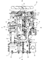
まず、主として図1〜図5を参照しながら、コモンレール式のディーゼルエンジン70の全体構造について説明する。なお、以下の説明では、クランク軸線aと平行な両側部(クランク軸線aを挟んで両側の側部)を左右、フライホイールハウジング78設置側を前側、冷却ファン76設置側を後側と称して、これらを便宜的に、ディーゼルエンジン70における四方及び上下の位置関係の基準としている。
(1). Overall Structure of Diesel Engine First, the overall structure of a common rail
図1〜図3に示すように、ディーゼルエンジン70におけるクランク軸線aと平行な一側部に吸気マニホールド73を、他側部に排気マニホールド71を備えている。実施形態では、シリンダヘッド72の左側面に吸気マニホールド73が配置されており、シリンダヘッド72の右側面に排気マニホールド71が配置されている。シリンダヘッド72は、クランク軸74とピストン(図示省略)が内蔵されたエンジンブロック75上に搭載されている。エンジンブロック75の前後両側面から、クランク軸74の前後先端側を突出させている。ディーゼルエンジン70におけるクランク軸線aと交差する一側部には、冷却ファン76が設けられている。実施形態では、エンジンブロック75の後側面側に冷却ファン76が位置している。クランク軸74の後端側からVベルト77を介して冷却ファン76に回転力を伝達するように構成されている。
As shown in FIGS. 1 to 3, the
図1〜図3に示す如く、ディーゼルエンジン70におけるクランク軸線aと交差する他側部(実施形態ではエンジンブロック75の前側面側)に、フライホイールハウジング78が固着されている。フライホイールハウジング78内にフライホイール79が配置されている。フライホイール79はクランク軸74の前端側に軸支されていて、クランク軸74と一体的に回転するように構成されている。作業機械(例えば油圧ショベルやフォークリフト等)の作動部に、フライホイール79を介してディーゼルエンジン70の動力を取り出すように構成されている。
As shown in FIGS. 1 to 3, a
また、エンジンブロック75の下面にはオイルパン81が配置されている。エンジンブロック75の左右側面とフライホイールハウジング78の左右側面とには、機関脚取付部82がそれぞれ設けられている。各機関脚取付部82には、防振ゴムを有する機関脚体83がボルト締結されている。ディーゼルエンジン70は、各機関脚体83を介して、作業機械(例えば油圧ショベルやフォークリフト等)等のエンジン支持シャーシ84に防振支持される。
An
吸気マニホールド73の入口側は、後述するEGR装置91(排気ガス再循環装置)のコレクタ92を介してエアクリーナ(図示省略)に連結されている。エアクリーナに吸い込まれた新気(外部空気)は、当該エアクリーナにて除塵・浄化されたのち、コレクタ92を介して吸気マニホールド73に送られ、そして、ディーゼルエンジン70の各気筒に供給される。
The inlet side of the
EGR装置91は、ディーゼルエンジン70の再循環排気ガス(排気マニホールド71からのEGRガス)と新気(エアクリーナからの外部空気)とを混合させて吸気マニホールド73に供給する中継管路としてのコレクタ(EGR本体ケース)92と、エアクリーナにコレクタ92を連通させる吸気スロットル部材93と、排気マニホールド71にEGRクーラ94を介して接続する還流管路としての再循環排気ガス管95と、再循環排気ガス管95にコレクタ92を連通させるEGRバルブ部材96とを有している。
The
すなわち、吸気マニホールド73と新気導入用の吸気スロットル部材93とがコレクタ92を介して連通接続されている。コレクタ92には、再循環排気ガス管95の出口側につながるEGRバルブ部材96が連通接続されている。コレクタ92は、前後長手の略筒状に形成されていて、当該コレクタ92の給気取入れ側(長手方向の前部側)に吸気スロットル部材93がボルト締結されている。コレクタ92の給気排出側は吸気マニホールド73の入口側にボルト締結されている。なお、EGRバルブ部材96は、その内部にあるEGRバルブ97(図15参照)の開度を調節することにより、コレクタ92へのEGRガスの供給量を調節するものである。
That is, the
コレクタ92内には新気が供給されると共に、排気マニホールド71からEGRバルブ部材96を介してコレクタ92内にEGRガス(排気マニホールド71から排出される排気ガスの一部)が供給される。新気と排気マニホールド71からのEGRガスとがコレクタ92内で混合されたのち、コレクタ92内の混合ガスが吸気マニホールド73に供給される。すなわち、ディーゼルエンジン70から排気マニホールド71に排出された排気ガスの一部が、吸気マニホールド73からディーゼルエンジン70に還流されることによって、高負荷運転時の最高燃焼温度が下がり、ディーゼルエンジン70からのNOx(窒素酸化物)の排出量が低減されることになる。
Fresh air is supplied into the
以上の構成から明らかなように、吸気マニホールド73と新気導入用の吸気スロットル部材93とを連通させる中継管路としてのコレクタ92を備えており、排気マニホールド71から延びる還流管路の出口側がEGRバルブ部材96を介してコレクタ92に連通接続されているから、新気とEGRガスとが吸気マニホールド73に送り込まれる前に混合されることになる。このため、混合ガス中においてEGRガスを広く分散でき、吸気マニホールド73に送り込まれる前段階でガス混合状態のバラツキ(ムラ)が少なくなる。その結果、ディーゼルエンジン70の各気筒にムラの少ない混合ガスを分配でき、各気筒間のEGRガス量のバラツキを抑制できる。その結果、黒煙の発生を抑制して、ディーゼルエンジン70の燃焼状態を良好に保ちながら、NOx量を低減できる。
As is apparent from the above configuration, the
図1及び図3に示すように、シリンダヘッド72の右側方で排気マニホールド71の上方には、ターボ過給機100が配置されている。ターボ過給機100は、タービンホイール(図示省略)を内蔵したタービンケース101と、ブロアホイール(図示省略)を内蔵したコンプレッサケース102とを有している。タービンケース101の排気ガス取入れ管105に、排気マニホールド71の出口側が接続されている。タービンケース101の排気ガス排出管103には、排気ガス浄化装置としてのディーゼルパティキュレートフィルタ1(以下、DPFという)を介してテールパイプ(図示省略)が接続される。ディーゼルエンジン70の各気筒から排気マニホールド71に排出された排気ガスは、ターボ過給機100及びDPF1等を経由して、テールパイプから外部に放出される。
As shown in FIGS. 1 and 3, a
一方、コンプレッサケース102の給気取入れ側に、給気管104を介してエアクリーナの給気排出側が接続される。コンプレッサケース102の給気排出側に、過給管108を介して吸気スロットル部材93の給気取入れ側が接続される。エアクリーナにて除塵された新気(外部空気)は、コンプレッサケース102から吸気スロットル部材93及びコレクタ92を経由して、吸気マニホールド73に送られ、そして、ディーゼルエンジン70の各気筒に供給される。
On the other hand, the supply / discharge side of the air cleaner is connected to the supply / intake side of the
排気ガス浄化装置としてのDPF1は、排気ガス中の粒子状物質(PM)等を捕集するためのものであり、図1〜図4に示すように、平面視でクランク軸74と交差する左右方向に長く延びた略円筒形状で、シリンダヘッド72の前側面に相対向するようにフライホイールハウジング78上に配置されている。DPF1の左右両側(長手方向一端側と長手方向他端側)には、排気ガス取入れ側と排気ガス排出側とが左右振り分けて設けられている。DPF1の排気ガス取入れ側は、タービンケース101の排気ガス排出管103に接続されている。DPF1の排気ガス排出側は、テールパイプ107の排気ガス取入れ側に接続されている。
The
DPF1は、耐熱金属材料製のDPFケーシング60に内蔵された略筒型の内側ケース4,20に、例えば白金等のディーゼル酸化触媒2とハニカム構造のスートフィルタ3とを直列に並べて収容した構造になっている(図6参照)。図1〜図4に示すように、実施形態のDPF1は、支持体としての左右一対のブラケット脚61,62を介してフライホイールハウジング78に取り付けられている。この場合、左ブラケット脚61の一端側は、DPFケーシング60の外周側に設けられたフランジにボルト締結されている。右ブラケット脚62の一端側は、DPFケーシング60の外周側に溶接固定されている。左右両ブラケット脚61,62の他端側は、フライホイールハウジング78の上面に形成されたDPF取付部80にボルト締結されている。つまり、上記したDPF1は、左右両ブラケット脚61,62とタービンケース101の排気ガス排出管103とにより、高剛性部材であるフライホイールハウジング78の上部に安定的に連結支持されている。
The
図1〜図4に示すように、DPFケーシング60には、内部の詰り状態を検出する差圧センサ63の入口側感知体64と出口側感知体65とが設けられている。差圧センサ63は、DPF1内におけるスートフィルタ3を挟んだ上流側及び下流側間の圧力差を検出するためのものである。当該圧力差に基づいてスートフィルタ3の粒子状物質堆積量を換算され、DPF1内の詰り状態を把握できる。差圧センサ63にて検出された圧力差に基づいて例えば吸気スロットル部材93を作動させることによって、スートフィルタ3の再生制御を実行するように構成されている。実施形態では、シリンダヘッド72の前側面に固定されたセンサブラケット66に検出本体67が取り付けられている。DPFケーシング60側の両感知体64,65は、それぞれハーネス68,69を介して差圧センサ63の検出本体67に接続されている。
As shown in FIGS. 1 to 4, the
上記の構成において、ディーゼルエンジン70の排気ガスは、タービンケース101の排気ガス排出管103から、DPFケーシング60のうちディーゼル酸化触媒2より上流側の空間に流入し、ディーゼル酸化触媒2からスートフィルタ3の順に通過して浄化処理される。排気ガス中の粒子状物質は、この段階でスートフィルタ3における各セル間の多孔質な仕切り壁を通り抜けできずに捕集される。その後、ディーゼル酸化触媒2及びスートフィルタ3を通過した排気ガスがテールパイプ107に放出される。
In the above configuration, the exhaust gas of the
排気ガスがディーゼル酸化触媒2及びスートフィルタ3を通過するに際して、排気ガス温度が再生可能温度(例えば約300℃)を超えていれば、ディーゼル酸化触媒2の作用にて、排気ガス中のNO(一酸化窒素)が不安定なNO2(二酸化窒素)に酸化する。そして、NO2がNOに戻る際に放出するO(酸素)にて、スートフィルタ3に堆積した粒子状物質が酸化除去されることにより、スートフィルタ3の粒子状物質捕集能力が回復する(スートフィルタ3が再生する)ことになる。
When the exhaust gas passes through the
(2).コモンレールシステム及びディーゼルエンジンの燃料系統構造
次に、図2、図7及び図8を参照しながら、コモンレールシステム117とディーゼルエンジン70の燃料系統構造を説明する。なお、図8では説明の便宜上、吸気マニホールド73に取り付けられるコレクタ92、EGRバルブ部材96等のEGR装置91の図示を省略している。図2、図7及び図8に示すように、ディーゼルエンジン70に設けられた4気筒分の各インジェクタ115に、燃料ポンプ116とコモンレールシステム117とを介して、燃料タンク118が接続されている。各インジェクタ115は、電磁開閉制御型の燃料噴射バルブ119を有している。コモンレールシステム117は、円筒状のコモンレール120(蓄圧室)を有している。
(2). Next, the fuel system structure of the
図2、図7及び図8に示すように、燃料ポンプ116の吸入側には、燃料フィルタ121及び低圧管122を介して燃料タンク118が接続される。燃料タンク118内の燃料が、燃料フィルタ121及び低圧管122を介して燃料ポンプ116に吸い込まれる。一方、燃料ポンプ116の吐出側には、高圧管123を介してコモンレール120が接続される。円筒状のコモンレール120の長手中途部に高圧管コネクタ124が設けられている。当該高圧管コネクタ124に、高圧管123の端部が高圧管コネクタナット125の螺着にて連結されている。また、コモンレール120には、4本の燃料噴射管126を介して4気筒分の各インジェクタ115がそれぞれ接続されている。円筒状のコモンレール120の長手方向に4気筒分の燃料噴射管コネクタ127が設けられている。当該燃料噴射管コネクタ127に、燃料噴射管126の端部が燃料噴射管コネクタナット128の螺着にて連結されている。
As shown in FIGS. 2, 7, and 8, a
上記の構成により、燃料タンク118の燃料が燃料ポンプ116によってコモンレール120に圧送され、高圧の燃料がコモンレール120に蓄えられる。各燃料噴射バルブ119がそれぞれ開閉制御されることによって、コモンレール120内の高圧の燃料が各インジェクタ115からディーゼルエンジン70の各気筒に噴射される。すなわち、各燃料噴射バルブ119を電子制御することによって、各インジェクタ115から供給される燃料の噴射圧力、噴射時期、噴射期間(噴射量)が高精度にコントロールされる。このため、ディーゼルエンジン70から排出される窒素酸化物(NOx)を低減できると共に、ディーゼルエンジン70の騒音振動を低減できる。
With the above configuration, the fuel in the
なお、図7に示すように、燃料タンク118には、ポンプ燃料戻り管129を介して燃料ポンプ116が接続されている。円筒状のコモンレール120の長手方向の端部に、コモンレール120内の燃料の圧力を制限する圧力調整バルブ付きの戻り管コネクタ130を介して、コモンレール燃料戻り管131が接続されている。燃料ポンプ116の余剰燃料とコモンレール120の余剰燃料とは、ポンプ燃料戻り管129及びコモンレール燃料戻り管131を介して、燃料タンク118に回収されることになる。
As shown in FIG. 7, a
(3).ディーゼルエンジンの吸気系の詳細構造
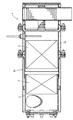
次に、主として図8〜図11を参照しながら、ディーゼルエンジン70の吸気系の詳細構造を説明する。ディーゼルエンジン70におけるクランク軸線aと平行な一側部(実施形態ではシリンダヘッド72の左側面)には、ディーゼルエンジン70の各気筒に向かう吸気ポート(図示省略)を開口させていると共に、これら各吸気ポートに新気及びEGRガスの混合ガスを分配するための吸気マニホールド73が取り付けられている(図8〜図10参照)。
(3). Detailed Structure of Intake System of Diesel Engine Next, a detailed structure of the intake system of the
吸気マニホールド73は横方向内向きに開口した前後長手の箱型に形成されている。実施形態では、横方向内向きのヘッド側開口部141の周囲に一体形成されたヘッド側フランジ142を複数本のボルト143にてシリンダヘッド72の左側面に締結することにより、吸気マニホールド73は、前記吸気ポート群に被さって連通した状態でシリンダヘッド72の左側面にフランジ接合されている。なお、図示は省略するが、ヘッド側フランジ142とシリンダヘッド72の左側面との間には、ヘッド側開口部141の周囲を囲う軟質材製のシール部材が介挿されている。吸気マニホールド73の横外側面(左側面)のうち冷却ファン76寄りの後部側には、入口側である給気取入れ側開口部144が形成されている。給気取入れ側開口部144の周囲には吸気側フランジ145が一体形成されている。
The
図8及び図9に示すように、吸気マニホールド73の下面側には前後一対の締結台部133が一体形成されている。また、コモンレール120には、吸気マニホールド73の締結台部133に対応する上向き突出状の締結ボス部134が一体形成されている。横方向外側(左方)からのレール取付ボルト135にて締結台部133に締結ボス134を締結することにより、コモンレール120は、吸気マニホールド73に沿って延びる姿勢で当該吸気マニホールド73に着脱可能に吊り下げ固定されている。実施形態では、吸気マニホールド73の左斜め下方の角隅部にコモンレール120を近接させている。また、コモンレール120は、これに設けられた高圧管コネクタ124及び燃料噴射管コネクタ127が横方向外向き(左外向き)になるように長手軸線回りに傾倒している(寝かされている)。
As shown in FIGS. 8 and 9, a pair of front and
一方、EGR装置91を構成する中継管路としてのコレクタ92は、吸気マニホールド73の横方向外側(実施形態では左側)に位置している。前述の通り、コレクタ92は前後長手の略筒状に形成されていて、吸気マニホールド73の横外側面(左側面)に、吸気マニホールド73の長手方向(前後方向)に沿って延びるように取り付けられている。従って、吸気マニホールド73とコレクタ92とは横並び状の配置関係に設定されている。
On the other hand, the
コレクタ92の横内側面(右側面)のうち冷却ファン76寄りの後部側には、給気排出側開口部146が形成されている。給気排出側開口部146の周囲にはコレクタ側フランジ147が一体形成されている。吸気マニホールド73の吸気側フランジ145にコレクタ側フランジ147を重ね合わせて複数本のボルト148にて締結することにより、吸気マニホールド73とコレクタ92とは、給気取入れ側開口部144と給気排出側開口部146とを連通させた状態でフランジ接合されている。そして、前述の通り、吸気スロットル部材93は、コレクタ92の給気取入れ側である長手方向の前部側にボルト締結されている。
An air supply /
従って、図11に示すように、吸気マニホールド73及びコレクタ92の内部は、吸気スロットル部材93から両開口部144,146の連通部分を経て各吸気ポートに至るまでの間をUターン状に折り返した吸気通路になっている。また、吸気マニホールド73とコレクタ92との連通部分(両開口部144,146の連通部分でもある)は、冷却ファン76寄りの後部側に位置している。なお、図示は省略するが、吸気側フランジ145とコレクタ側フランジ147との間には、給気取入れ側開口部144及び給気排出側開口部146の周囲を囲う軟質材製のシール部材が介挿されている。
Therefore, as shown in FIG. 11, the inside of the
図10及び図11に示すように、コレクタ92における連通部分寄りの部位には、平面視で吸気マニホールド73に近付くに連れてクランク軸線aと交差する方向(実施形態では左右方向)の長さが短くなる傾斜部150が形成されている。換言すると、コレクタ92における連通部分寄りの部位は、平面視で角を斜めに切り落としたような形状の傾斜部150になっている。図11に示すように、傾斜部150の傾斜内面151は、コレクタ92の給気取入れ側の通路に被さる状態になっていて、吸気スロットル部材93から流入する新気のうち一方の内側面(左内側面)に沿って流れるものを、傾斜内面151にて中心(真ん中寄り)の方向に偏流させるように構成されている。コレクタ92の上面のうち傾斜部150の上流側には、上向きに開口する還流開口部152が形成されている。還流開口部152の周囲にはバルブ用フランジ153が一体形成されている。バルブ用フランジ153上にEGRバルブ部材96のEGRガス排出側がボルト締結されている。
As shown in FIGS. 10 and 11, the portion of the
上記の構成において、吸気スロットル部材93からコレクタ92内に流入した新気は冷却ファン76(後方側)に向けて流れる。前記新気のうち一方の内側面(左内側面)に沿って流れるものは、傾斜部150の傾斜内面151に衝突して、還流開口部152の下方付近で中心の方向に偏流する。このため、還流開口部152の下方付近では、新気の流れが図11に示す反時計回りの渦を形成するかのように乱れることになる。このように乱れた新気の流れに対して、再循環排気ガス管95からのEGRガスは、EGRバルブ部材96を介して上方から流入するから、EGRガスは、コレクタ92内への流入と同時に、内部を流れる新気にスムーズに混合される。従って、コレクタ92内において、新気とEGRガスとを吸気マニホールド73に送り込む前に撹拌しながら効率よく混合でき(混合ガス中においてEGRガスをスムーズに分散でき)、コレクタ92内でのガス混合状態のバラツキ(ムラ)をより確実に抑制できる。
In the above configuration, fresh air that has flowed into the
還流開口部152の下方付近で混合された混合ガスは、傾斜部150の傾斜内面151に沿って給気排出側開口部146(連通部分)に案内され、給気取入れ側開口部144からフライホイールハウジング78側(前方側)に方向転換して、吸気マニホールド73内を流れ、ディーゼルエンジン70の各気筒に分配される。このように吸気マニホールド73内部の混合ガスの流れ方向は、給気取入れ側開口部144からフライホイールハウジング78側に向かう一方方向になるから、ディーゼルエンジン70の各気筒にムラの少ない混合ガスを分配して、各気筒間のEGRガス量がばらつくのを格段に低減できる。その結果、黒煙の発生が抑制され、ディーゼルエンジン70の燃焼状態を良好に保ちながら、NOx量を低減できる。すなわち、特定の気筒で失火を招来することなく、EGRガスの還流による排気ガスの清浄化(クリーン化)を達成できるのである。
The mixed gas mixed in the vicinity of the lower part of the
上記の記載並びに図1、図2、図9及び図10から明らかなように、クランク軸線aと平行な一側部に吸気マニホールド73を、他側部に排気マニホールド71を備えていると共に、前記排気マニホールド71から排出される排気ガスの一部をEGRガスとして前記吸気マニホールド73に還流させるEGR装置91を備えているエンジン70であって、前記吸気マニホールド73と新気導入用の吸気スロットル部材93とを連通させる中継管路92を備えており、前記排気マニホールド71から延びる還流管路95の出口側が前記中継管路92に連通接続されており、前記中継管路92は、前記吸気マニホールド73の横外側部に、前記吸気マニホールド73に沿って延びるように取り付けられているから、新気とEGRガスとを前記吸気マニホールド73に送り込む前に混合して、ガス混合状態のバラツキ(ムラ)を少なくできる。その上、前記中継管路92を前記吸気マニホールド73の横外側方に位置させて、前記エンジン70の全高を低く抑制でき、前記エンジン70のコンパクト化に寄与するという効果を奏する。
As apparent from the above description and FIGS. 1, 2, 9 and 10, the
また、前記中継管路92は、前記吸気マニホールド73の横外側部に、前記吸気マニホールド73に沿って延びるように取り付けられているから、前記中継管路92の長さを前記吸気マニホールド73の長手方向に沿って長くできるので、新気とEGRガスとの混合空間が広がり、新気とEGRガスとの混合促進に寄与する(混合ガス中においてEGRガスをより効率よくに拡散させることが可能になる)という効果を奏する。
Further, since the
上記の記載並びに図1、図2、図9及び図10から明らかなように、前記クランク軸線aと交差する一側部に冷却ファン76を備えており、前記吸気マニホールド73と前記中継管路92との連通部分144,146が前記冷却ファン76寄りに形成されているから、吸気マニホールド73内部の混合ガスの流れ方向が一方方向になる。このため、前記エンジン70の各気筒にムラの少ない混合ガスを分配でき、前記各気筒間のEGRガス量がばらつくのを格段に低減できる。また、前記吸気マニホールド73と前記中継管路92との連通部分144,146に冷却ファン76からの冷却風が当たるので、ムラの少なくなった混合ガスの冷却に効果的である。その結果、黒煙の発生が抑制され、前記エンジン70の燃焼状態を良好に保ちながら、NOx量を確実に低減できる。すなわち、特定の気筒で失火を招来することなく、EGRガスの還流による排気ガスの清浄化(クリーン化)を達成できるという効果を奏する。
As apparent from the above description and FIGS. 1, 2, 9 and 10, a cooling
上記の記載並びに図9〜図11から明らかなように、前記中継管路92における前記連通部分寄りの部位には、平面視で前記吸気マニホールド73に近付くに連れて前記クランク軸線aと交差する方向の長さが短くなる傾斜部150が形成されており、前記中継管路92のうち前記傾斜部150の上流側に前記還流管路95の出口側が連通接続されているから、前記中継管路92に流入した新気のうち一方の内側面(左内側面)に沿って流れるものは、前記傾斜部150の内面側に衝突して、前記中継管路92における前記還流管路95の出口側付近で中心の方向に偏流する。このため、前記中継管路92における前記還流管路95の出口側付近では、新気の流れが渦を形成するかのように乱れる。このように乱れた新気の流れに対して、前記還流管路95からのEGRガスが前記中継管路92内に流入するから、EGRガスは、前記中継管路92内への流入と同時に、内部を流れる新気にスムーズに混合される。従って、前記中継管路92内において、新気とEGRガスとを前記吸気マニホールド73に送り込む前に撹拌しながら効率よく混合でき(混合ガス中においてEGRガスをスムーズに分散でき)、前記中継管路92内でのガス混合状態のバラツキ(ムラ)をより確実に抑制できるという効果を奏する。
As is apparent from the above description and FIGS. 9 to 11, the portion near the communication portion in the
(4).再循環排気ガス管とEGRバルブ部材との接続構造
次に、主として図12〜図15を参照しながら、再循環排気ガス管95とEGRバルブ部材96との接続構造について説明する。図1、図2、図12及び図13に示すように、吸気マニホールド73の上方には、吸気マニホールド73へのEGRガスの供給量を調節するためのEGRバルブ部材96が配置されている。実施形態では、吸気マニホールド73の横方向外側(実施形態では左側)に位置するコレクタ92上に、EGRバルブ部材96が吸気マニホールド73の長手方向(クランク軸線aと平行な前後方向)に沿って延びた姿勢で配置されている。コレクタ92のバルブ用フランジ153に、EGRバルブ部材96における下向き開口状のEGRガス排出側がボルト締結されている。
(4). Connection Structure Between Recirculation Exhaust Gas Pipe and EGR Valve Member Next, a connection structure between the recirculation
一方、シリンダヘッド72の上面のうち吸気マニホールド73寄りの部位からは、4気筒分のインジェクタ115の上部側が、クランク軸線aと平行な前後方向に並んだ状態で上向きに突出している。シリンダヘッド72の上面のうち排気マニホールド71寄りの部位にはヘッドカバー160が取り付けられている。従って、各インジェクタ115の上部側は、ヘッドカバー160にて覆われずにシリンダヘッド72上に露出している。また、EGRバルブ部材96とヘッドカバー160とは、例えば冷却ファン76側から見た側面視で、シリンダヘッド72及び吸気マニホールド73の上面に比して一段高い状態になっている。従って、ディーゼルエンジン70の上部(EGRバルブ部材96とヘッドカバー160との間)は上向き凹状に凹んでいて、当該凹み空間(EGRバルブ部材96とヘッドカバー160との間において前後に延びる凹み空間)が、冷却ファン76からフライホイールハウジング78側へ向かう冷却風が通過する通風路161になっている。
On the other hand, from the portion of the upper surface of the
図12及び図14に示すように、排気マニホールド71から延びる還流管路としての再循環排気ガス管95の出口側を、平面視で通風路161寄りに位置させるべく、EGRバルブ部材96のEGRガス取入れ側に対してオフセットさせている。そして、再循環排気ガス管95の出口側とEGRバルブ部材96のEGRガス取入れ側とが中間継手162を介して連結されている。なお、図15に示すように、EGRバルブ部材96のEGRガス取入れ側の開口部には、当該開口部を開閉するためのEGRバルブ97が設けられている。
As shown in FIGS. 12 and 14, the EGR gas of the
図12、図14及び図15に示すように、中間継手162は平面視逆S字の筒状に形成されている。中間継手162におけるガス管側開口部163の直径Dgは、バルブ側開口部164の直径Dbより小さく設定されている。ガス管側開口部163の中心線Cgはバルブ側開口部164の中心線Cbに対して適宜寸法だけ上方にオフセットしている。中間継手162におけるガス管側開口部163とバルブ側開口部164との間の中間連通部165には、両開口部163,164の直径Dg,Db及びオフセット位置の関係で、ガス管側開口部163からバルブ側開口部164に向けて段状に下がる段差166が形成されている。中間継手162の中間連通部165のうち段差166と対峙する内部には、当該段差166の上方に被さるように内向き突出する隆起部167が形成されている。中間継手162のバルブ側開口部164付近では、内向き突出状の隆起部167の存在によって、ガス管側開口部163から段差166を介して流れ降りてくるEGRガスを、バルブ側開口部164の中心線Cb回りに旋回させて、渦流を形成するように構成されている。
As shown in FIGS. 12, 14, and 15, the intermediate joint 162 is formed in a cylindrical shape having an inverted S shape in plan view. The diameter Dg of the gas
上記の構成において、排気マニホールド71から再循環排気ガス管95を介して中間継手162のガス管側開口部163内に流入したEGRガスは、中間連通部165のうち段差166より上流側の湾曲内面168に衝突して、段差166側に流れ降りていく。このとき、再循環排気ガス管95の出口側が平面視で通風路161寄りにオフセットして位置している関係上、中間継手162の湾曲内面168周辺(外周部)は、EGRバルブ部材96よりも通風路161寄りに突き出ていて、冷却ファン76からの冷却風が当たっている。このため、冷却風による中間継手162の温度上昇を抑制し、ひいてはその内部のEGRガス温度を低下できる。その結果、混合ガスの冷却に寄与して、混合ガスによるNOx量低減効果を適正な状態に維持し易くなるという効果を奏する。
In the above configuration, the EGR gas that has flowed into the gas pipe side opening 163 of the intermediate joint 162 from the
ガス管側開口部163から段差166を介して流れ降りてくるEGRガスは、内向き突出状の隆起部167の存在にて、バルブ側開口部164付近でその中心線Cb回りに旋回し渦流を形成しながら、EGRバルブ部材96のEGRガス取入れ側に送り込まれる。そうすると、渦流状のEGRガスは、EGRバルブ97の開放時に、EGRバルブ97に遮られることなく、EGRバルブ97とEGRガス取入れ側の開口部との間の隙間にスムーズに流入することになる。従って、EGRバルブ部材96を経由したEGRガスと新気との混合の円滑化を図れるという効果を奏する。かかる構成は、実施形態のように、ターボ過給機100を用いて新気を圧縮して吸気マニホールド73に供給する場合に特に有益である。吸気マニホールド73やコレクタ92内の圧縮空気の圧力は、EGRバルブ部材96内にEGRガスを流入し難くする方向に寄与するが、EGRガスを渦流にすることによって、流入し難さを打ち消す方向に貢献できるからである。
The EGR gas flowing down from the gas
なお、実施形態では、中間継手162におけるガス管側開口部163の直径Dgがバルブ側開口部164の直径Dbより小さく設定されているから、ガス管側開口部163からバルブ側開口部164に至る経路の断面積を中間連通部165において拡大できる。従って、ガス管側開口部163からバルブ側開口部164に至るEGRガスの流れ抵抗の増大を回避できるという利点もある。
In the embodiment, since the diameter Dg of the gas
さて、図2、図9及び図12に示すように、中間継手162のうち隆起部167より上流側(実施形態ではガス管側開口部163付近の外面側)には、中間継手162に流入したEGRガスの温度を検出するEGRガス温度センサ171が取り付けられている。また、コレクタ92のうち吸気スロットル部材93寄りの部位に、新気の温度を検出する新気温度センサ172が取り付けられている。コレクタ92の傾斜部150には、混合ガスの温度を検出するための混合ガス温度センサ173が取り付けられている。温度センサ171〜173群は、混合ガスのEGR率を求めるのに用いられるものである。ここで、EGR率とは、EGRガス量と新気量との和で、EGRガス量を割った値(=EGRガス量/(EGRガス量+新気量))のことを言う。
As shown in FIGS. 2, 9, and 12, the intermediate joint 162 flows into the intermediate joint 162 on the upstream side of the raised portion 167 (in the embodiment, the outer surface side near the gas pipe side opening 163). An EGR
この場合、各ガスの流量や流速を検出するための手段(センサ)がなくても、新気温度、EGRガス温度及び混合ガス温度を用いて、簡単に精度よくEGR率を算出できる。また、これらの算出結果に基づいてEGRバルブ部材96をフィードバック制御する構成を採用することによって、各ガスの流量や流速を検出してEGR率を求める複雑な制御システムを構築しなくても、コレクタ92に適正量のEGRガスを供給できる。
In this case, even if there is no means (sensor) for detecting the flow rate and flow velocity of each gas, the EGR rate can be calculated easily and accurately using the fresh air temperature, the EGR gas temperature, and the mixed gas temperature. Further, by adopting a configuration in which the
更に、EGRガス温度センサ171が中間継手162のうち隆起部167より上流側に取り付けられているので、EGRバルブ部材96に流入する前の比較的流速が速い箇所に、EGRガス温度センサ171は位置することになる。このため、EGRガスによるEGRガス温度センサ171の汚れや性能劣化を防止できるという効果を奏する。その上、新気が混ざり得ない箇所でEGRガスの温度測定をすることになるから、正確なEGRガス温度を測定できるというメリットもある。
Further, since the EGR
上記の記載並びに図12〜図15から明らかなように、シリンダヘッド72のうちクランク軸線aと平行な一側部に吸気マニホールド73を、他側部に排気マニホールド71を備えていると共に、前記排気マニホールド71から排出される排気ガスの一部をEGRガスとして前記吸気マニホールド73に還流させるEGR装置91を備えているエンジン70であって、前記吸気マニホールド73の上方に配置されたEGRバルブ部材96と、前記シリンダヘッド72上のヘッドカバー160との間は、冷却ファン76からの冷却風が通過する通風路161になっており、前記排気マニホールド71から延びる還流管路95の出口側を、平面視で前記通風路161寄りに位置するように前記EGRバルブ部材96に対してオフセットさせ、前記還流管路95の出口側と前記EGRバルブ部材96のEGRガス取入れ側とが中間継手162を介して連結されているから、前記中間継手162のうち前記通風路161寄りの部位には、前記冷却ファン76からの冷却風が当たることになる。このため、冷却風による前記中間継手162の温度上昇を抑制し、ひいてはその内部のEGRガス温度を低下できる。その結果、混合ガスの冷却に寄与して、混合ガスによるNOx量低減効果を適正な状態に維持し易くなるという効果を奏する。
As apparent from the above description and FIGS. 12 to 15, the
上記の記載並びに図14及び図15から明らかなように、前記中間継手162のうちEGRガス排出側の内部には、EGRガスを前記EGRガス排出側の中心線Cb回りに旋回させるための隆起部167が形成されているから、EGRガス取入れ側163から流れてくるEGRガスは、内向き突出状の前記隆起部167の存在にて、前記EGRガス排出側164付近でその中心線Cb回りに旋回し渦流を形成しながら、前記EGRバルブ部材96のEGRガス取入れ側に送り込まれる。そうすると、渦流状のEGRガスは、EGRバルブ97の開放時に、前記EGRバルブ97に遮られることなく、前記EGRバルブ部材96のEGRガス取入れ側の開口部と前記EGRバルブ97との間の隙間にスムーズに流入することになる。従って、前記EGRバルブ部材96を経由したEGRガスと新気との混合の円滑化を図れるという効果を奏する。
As apparent from the above description and FIGS. 14 and 15, the intermediate joint 162 has an elevated portion for turning EGR gas around the center line Cb on the EGR gas discharge side inside the EGR gas discharge side. Since 167 is formed, the EGR gas flowing from the EGR
上記の記載並びに図12、図14及び図15から明らかなように、前記中間継手162のうち前記隆起部167より上流側に、EGRガスの温度を検出するためのEGRガス温度センサ171が取り付けられているから、前記EGRバルブ部材96に流入する前の比較的流速が速い箇所に、前記EGRガス温度センサ171は位置することになる。このため、EGRガスによる前記EGRガス温度センサ171の汚れや性能劣化を防止できるという効果を奏する。その上、新気が混ざり得ない箇所でEGRガスの温度測定をすることになるから、正確なEGRガス温度を測定できるというメリットもある。
As apparent from the above description and FIGS. 12, 14 and 15, an EGR
(5).その他
なお、本願発明は、前述の実施形態に限定されるものではなく、様々な態様に具体化できる。例えば本願発明に係るエンジンは、例えばコンバイン、トラクタ等の農作業機や、バックホウ、フォークリフトカー等の特殊作業用車両のような各種車両に対して広く適用できる。また、本願発明における各部の構成は図示の実施形態に限定されるものではなく、本願発明の趣旨を逸脱しない範囲で種々変更が可能である。
(5). Others The present invention is not limited to the above-described embodiments, and can be embodied in various forms. For example, the engine according to the present invention can be widely applied to various vehicles such as agricultural working machines such as a combine and a tractor, and special work vehicles such as a backhoe and a forklift car. Moreover, the structure of each part in this invention is not limited to embodiment of illustration, A various change is possible in the range which does not deviate from the meaning of this invention.
a クランク軸線
Cb バルブ側開口部の中心線
1 DPF
2 ディーゼル酸化触媒
3 スートフィルタ
60 DPFケーシング
70 ディーゼルエンジン
71 排気マニホールド
73 吸気マニホールド
74 クランク軸
75 エンジンブロック
76 冷却ファン
78 フライホイールハウジング
91 EGR装置
92 コレクタ
93 吸気スロットル部材
94 EGRクーラ
95 再循環排気ガス管
96 EGRバルブ部材
97 EGRバルブ
160 ヘッドカバー
161 通風路
162 中間継手
163 ガス管側開口部
164 バルブ側開口部
165 中間連通部
167 隆起部
a Crank axis
2 Diesel oxidation catalyst 3
Claims (2)
前記EGR装置を前記排気マニホールドにEGRクーラを介して接続するとともに、前記排気ガス浄化装置の排気入口側を前記排気マニホールドの排気出口側と過給機を介して連通させており、
前記排気ガス浄化装置を、前記エンジンのうち前記クランク軸線と直行する一側部に設けられたフライホイールハウジングの上部に配置するとともに、前記EGRクーラと前記過給機とを前記エンジンのうち前記クランク軸線と平行な一側部に配置したことを特徴とする、
エンジン。 An exhaust manifold on one side parallel to the crank axis of the cylinder head and an exhaust manifold on the other side, and an exhaust gas purifying device for purifying and exhausting exhaust gas discharged from the exhaust manifold; An engine having an EGR device that recirculates a part of the exhaust gas from the exhaust manifold to the intake manifold as EGR gas,
The EGR device is connected to the exhaust manifold via an EGR cooler, and the exhaust inlet side of the exhaust gas purification device is connected to the exhaust outlet side of the exhaust manifold via a supercharger.
The exhaust gas purifying device is disposed on an upper portion of a flywheel housing provided on one side of the engine that is orthogonal to the crank axis, and the EGR cooler and the supercharger are disposed in the crank of the engine. It is arranged on one side parallel to the axis,
engine.
前記EGRクーラと前記EGR装置とを連結する環流管路を、前記排気ガス浄化装置と前記過給機とを連通させる排気ガス排出管の下側で、該排気ガス排出管と交差させたことを特徴とする、
請求項1に記載したエンジン。 The exhaust gas purification device is arranged in parallel to the direction orthogonal to the crank axis, and the EGR device is arranged on one side of the engine parallel to the crank axis,
A reflux line connecting the EGR cooler and the EGR device crosses the exhaust gas discharge pipe below the exhaust gas discharge pipe that connects the exhaust gas purification device and the supercharger. Features
The engine according to claim 1.
Priority Applications (1)
| Application Number | Priority Date | Filing Date | Title |
|---|---|---|---|
| JP2014215437A JP2015014292A (en) | 2014-10-22 | 2014-10-22 | Engine |
Applications Claiming Priority (1)
| Application Number | Priority Date | Filing Date | Title |
|---|---|---|---|
| JP2014215437A JP2015014292A (en) | 2014-10-22 | 2014-10-22 | Engine |
Related Parent Applications (1)
| Application Number | Title | Priority Date | Filing Date |
|---|---|---|---|
| JP2013110539A Division JP5638660B2 (en) | 2013-05-27 | 2013-05-27 | engine |
Publications (1)
| Publication Number | Publication Date |
|---|---|
| JP2015014292A true JP2015014292A (en) | 2015-01-22 |
Family
ID=52436156
Family Applications (1)
| Application Number | Title | Priority Date | Filing Date |
|---|---|---|---|
| JP2014215437A Pending JP2015014292A (en) | 2014-10-22 | 2014-10-22 | Engine |
Country Status (1)
| Country | Link |
|---|---|
| JP (1) | JP2015014292A (en) |
Cited By (6)
| Publication number | Priority date | Publication date | Assignee | Title |
|---|---|---|---|---|
| JP2018018046A (en) * | 2016-07-27 | 2018-02-01 | 光環科技股▲ふん▼有限公司 | Optical coupling structure and optical communication device |
| JP2019065808A (en) * | 2017-10-04 | 2019-04-25 | いすゞ自動車株式会社 | Intake system structure for internal combustion engine |
| US10858975B2 (en) * | 2017-06-15 | 2020-12-08 | Yanmar Power Technology Co., Ltd. | Engine |
| WO2022070690A1 (en) | 2020-09-30 | 2022-04-07 | ヤンマーホールディングス株式会社 | Diesel engine |
| CN114687853A (en) * | 2016-04-08 | 2022-07-01 | 洋马动力科技有限公司 | Engine device |
| US12098670B2 (en) | 2020-09-30 | 2024-09-24 | Yanmar Holdings Co., Ltd. | Diesel engine |
Citations (5)
| Publication number | Priority date | Publication date | Assignee | Title |
|---|---|---|---|---|
| JP2007085302A (en) * | 2005-09-26 | 2007-04-05 | Kubota Corp | Multicylinder engine |
| JP2007092595A (en) * | 2005-09-28 | 2007-04-12 | Kubota Corp | Multicylinder engine |
| JP2008014232A (en) * | 2006-07-06 | 2008-01-24 | Yanmar Co Ltd | Engine exhaust gas recirculation system |
| JP2008196315A (en) * | 2007-02-08 | 2008-08-28 | Iseki & Co Ltd | Diesel engine |
| JP2011012572A (en) * | 2009-06-30 | 2011-01-20 | Yanmar Co Ltd | Engine |
-
2014
- 2014-10-22 JP JP2014215437A patent/JP2015014292A/en active Pending
Patent Citations (5)
| Publication number | Priority date | Publication date | Assignee | Title |
|---|---|---|---|---|
| JP2007085302A (en) * | 2005-09-26 | 2007-04-05 | Kubota Corp | Multicylinder engine |
| JP2007092595A (en) * | 2005-09-28 | 2007-04-12 | Kubota Corp | Multicylinder engine |
| JP2008014232A (en) * | 2006-07-06 | 2008-01-24 | Yanmar Co Ltd | Engine exhaust gas recirculation system |
| JP2008196315A (en) * | 2007-02-08 | 2008-08-28 | Iseki & Co Ltd | Diesel engine |
| JP2011012572A (en) * | 2009-06-30 | 2011-01-20 | Yanmar Co Ltd | Engine |
Cited By (7)
| Publication number | Priority date | Publication date | Assignee | Title |
|---|---|---|---|---|
| CN114687853A (en) * | 2016-04-08 | 2022-07-01 | 洋马动力科技有限公司 | Engine device |
| JP2018018046A (en) * | 2016-07-27 | 2018-02-01 | 光環科技股▲ふん▼有限公司 | Optical coupling structure and optical communication device |
| US10858975B2 (en) * | 2017-06-15 | 2020-12-08 | Yanmar Power Technology Co., Ltd. | Engine |
| JP2019065808A (en) * | 2017-10-04 | 2019-04-25 | いすゞ自動車株式会社 | Intake system structure for internal combustion engine |
| WO2022070690A1 (en) | 2020-09-30 | 2022-04-07 | ヤンマーホールディングス株式会社 | Diesel engine |
| KR20230078630A (en) | 2020-09-30 | 2023-06-02 | 얀마 홀딩스 주식회사 | diesel |
| US12098670B2 (en) | 2020-09-30 | 2024-09-24 | Yanmar Holdings Co., Ltd. | Diesel engine |
Similar Documents
| Publication | Publication Date | Title |
|---|---|---|
| JP5390281B2 (en) | Exhaust gas purification device | |
| JP5508617B2 (en) | Fuel injection system and engine equipped with the same | |
| KR101959595B1 (en) | Engine device | |
| JP6000552B2 (en) | Engine equipment | |
| US9783042B2 (en) | Working vehicle | |
| JP2015014292A (en) | Engine | |
| KR20140108656A (en) | Engine device | |
| JP5843608B2 (en) | Engine equipment | |
| JP5399145B2 (en) | engine | |
| JP5443076B2 (en) | engine | |
| JP5638660B2 (en) | engine | |
| JP2013148009A (en) | Engine device | |
| JP5420997B2 (en) | engine | |
| JP2013160146A (en) | Exhaust emission control device | |
| JP2014040836A (en) | Engine device | |
| JP5898714B2 (en) | Engine equipment | |
| JP5909098B2 (en) | Exhaust gas purification device | |
| JP5364149B2 (en) | Exhaust gas purification device | |
| JP5537538B2 (en) | Exhaust gas purification device | |
| JP6067092B2 (en) | Engine equipment | |
| JP2015183545A (en) | Engine device | |
| JP5872301B2 (en) | Exhaust gas purification device | |
| JP2014040834A (en) | Engine device | |
| JP2010180794A (en) | Egr device, and engine device with the same to be mounted on working vehicle | |
| JP5820901B2 (en) | EGR device and engine device mounted on work vehicle equipped with the same |
Legal Events
| Date | Code | Title | Description |
|---|---|---|---|
| A621 | Written request for application examination |
Free format text: JAPANESE INTERMEDIATE CODE: A621 Effective date: 20141022 |
|
| A977 | Report on retrieval |
Free format text: JAPANESE INTERMEDIATE CODE: A971007 Effective date: 20150730 |
|
| A131 | Notification of reasons for refusal |
Free format text: JAPANESE INTERMEDIATE CODE: A131 Effective date: 20150812 |
|
| A521 | Written amendment |
Free format text: JAPANESE INTERMEDIATE CODE: A523 Effective date: 20151008 |
|
| A131 | Notification of reasons for refusal |
Free format text: JAPANESE INTERMEDIATE CODE: A131 Effective date: 20160224 |
|
| A521 | Written amendment |
Free format text: JAPANESE INTERMEDIATE CODE: A523 Effective date: 20160412 |
|
| A02 | Decision of refusal |
Free format text: JAPANESE INTERMEDIATE CODE: A02 Effective date: 20160818 |