JP2015010809A - Drying device - Google Patents
Drying device Download PDFInfo
- Publication number
- JP2015010809A JP2015010809A JP2013138851A JP2013138851A JP2015010809A JP 2015010809 A JP2015010809 A JP 2015010809A JP 2013138851 A JP2013138851 A JP 2013138851A JP 2013138851 A JP2013138851 A JP 2013138851A JP 2015010809 A JP2015010809 A JP 2015010809A
- Authority
- JP
- Japan
- Prior art keywords
- dried
- temperature
- cylindrical body
- moisture content
- partition plate
- Prior art date
- Legal status (The legal status is an assumption and is not a legal conclusion. Google has not performed a legal analysis and makes no representation as to the accuracy of the status listed.)
- Granted
Links
Images


Landscapes
- Drying Of Solid Materials (AREA)
Abstract
Description
本発明は、一般工業製品やフィッシュミール等の飼料、肥料製造用として、また、合成樹脂等の化学製品製造用として、あるいは工場廃水や下水処理にともなって排出される産廃スラッジや汚泥などを乾燥する乾燥装置に関するものである。 The present invention dries industrial waste sludge, sludge, etc. discharged for general industrial products, fish meal and other feeds, fertilizer production, chemical resin production such as synthetic resin, or factory wastewater and sewage treatment. The present invention relates to a drying apparatus.
一般に、食品の残渣物や水処理装置から発生するスラッジや汚泥等は、内部に含有されている水分などを蒸発させる減量処理が行われる。ここで、水分などを蒸発させるために処理物に対して直接熱風を吹き当てることで乾燥させる直接乾燥法や、スチームなどの熱媒体によって容器などの接触部材を加熱してこの加熱された接触部材を処理物と接触させることで処理物に間接的に熱を伝えて乾燥させる間接乾燥法がある。 Generally, sludge and sludge generated from food residues and water treatment devices are subjected to a weight reduction process that evaporates moisture contained therein. Here, in order to evaporate moisture etc., the contact member such as a container is heated by a direct drying method in which hot air is directly blown against the processed material, or a heating medium such as steam, and the heated contact member. There is an indirect drying method in which heat is indirectly transferred to a treated product by bringing the treated product into contact with the treated product.
上述の間接乾燥法を採用した乾燥装置として、両端に側壁が設けられた筒状体を有する固定体と、この固定体に対して回転自在に挿通された回転軸とを備える乾燥装置が開示されている(例えば、特許文献1参照)。ここで、回転軸には撹拌羽根が複数連設されており、各撹拌羽根が内部を流通する熱媒体によって加熱されている。また、筒状体の外周部には、ジャケットが設けられており、このジャケット内にも熱媒体が流通する構造とされている。
そして、筒状体の内部に供給された被乾燥物(処理物)を複数の撹拌羽根で撹拌、乾燥させながら移送する。このとき、撹拌羽根を複数設けることで、被乾燥物との接触面積が増大して効率よく被乾燥物を乾燥させることができる。
As a drying apparatus employing the indirect drying method described above, a drying apparatus including a fixed body having a cylindrical body with side walls provided at both ends and a rotating shaft that is rotatably inserted into the fixed body is disclosed. (For example, refer to Patent Document 1). Here, a plurality of stirring blades are connected to the rotating shaft, and each stirring blade is heated by a heat medium that circulates inside. In addition, a jacket is provided on the outer peripheral portion of the cylindrical body, and a heat medium flows through the jacket.
And the to-be-dried material (processed material) supplied in the inside of a cylindrical body is conveyed, stirring and drying with a some stirring blade. At this time, by providing a plurality of stirring blades, the contact area with the object to be dried increases, and the object to be dried can be efficiently dried.
ところで、このような乾燥装置において、取扱いが容易となるなどの理由から、筒状体から排出される被乾燥物中の水分量が一定であることが望まれている。ここで、排出される被乾燥物中の水分量の調整方法としては、例えば、排出される被乾燥物の筒状体内における滞留時間を調整することによって排出される被乾燥物中の水分量を調整する方法がある。これは、固定体に筒状体の内部と接続されて移送された被乾燥物を排出する被乾燥物排出部を設け、この被乾燥物排出部に筒状体で乾燥されて筒状体から移送された被乾燥物が流通する流路を形成し、仕切板でこの流路の堰止め高さを調整して排出される被乾燥物の滞留時間を調整する方法である(例えば、特許文献2参照)。 By the way, in such a drying apparatus, it is desired that the moisture content in the material to be dried discharged from the cylindrical body is constant for reasons such as easy handling. Here, as a method for adjusting the amount of water in the discharged to-be-dried object, for example, the amount of moisture in the to-be-dried object to be discharged is adjusted by adjusting the residence time of the to-be-dried object to be discharged in the cylindrical body. There is a way to adjust. This is provided with a to-be-dried object discharge part for discharging the object to be dried which is connected to the inside of the cylindrical body and fixed to the fixed body, and is dried by the cylindrical body to the to-be-dried object discharging part. This is a method of adjusting the residence time of the to-be-dried material to be discharged by forming a channel through which the to-be-dried material is circulated and adjusting the weir height of this channel with a partition plate (for example, patent document) 2).
ここで、流路の堰止め高さを高くすると、この仕切板を乗り越えるようにして流通する被乾燥物が排出されにくくなるので、筒状体内に被乾燥物が滞留することになる。このため、被乾燥物の乾燥時間が長くなり、被乾燥物中の水分量が少なくなる。逆に、流路の堰止め高さを低くすると、被乾燥物が筒状体内に滞留しにくくなるので、乾燥時間が短くなり、水分量が比較的多くなる。このように堰止め高さを調整して乾燥時間を適宜変更することで、排出された被乾燥物中の水分量が調整される。 Here, when the weir height of the flow path is increased, the material to be dried flowing over the partition plate is difficult to be discharged, so that the material to be dried stays in the cylindrical body. For this reason, the drying time of a to-be-dried object becomes long, and the moisture content in a to-be-dried object decreases. Conversely, when the weir height of the flow path is lowered, the material to be dried is less likely to stay in the cylindrical body, so the drying time is shortened and the amount of water is relatively large. In this way, by adjusting the weir height and appropriately changing the drying time, the amount of moisture in the discharged material to be dried is adjusted.
しかしながら、投入される被乾燥物(処理物)は、含有する水分量が変動する場合があり、特許文献1及び特許文献2に開示された乾燥装置を使用しても排出される被乾燥物の水分量が一定しない問題があった。
特に、近年、コスト削減、品質安定の観点から、排出される被乾燥物の水分量を安定させることが求められており、さらに効率的に被乾燥物を乾燥させるとともに、被乾燥物の水分量のバラつきを低減できる乾燥装置が必要とされている。
However, the to-be-dried product (processed product) may contain a variable amount of water, and the to-be-dried product to be discharged even if the drying apparatus disclosed in
In particular, in recent years, from the viewpoint of cost reduction and quality stability, it has been required to stabilize the moisture content of the discharged material to be discharged, and more efficiently dry the material to be dried and the moisture content of the material to be dried. There is a need for a drying device that can reduce the variation in the size.
この発明は前述した事情に鑑みてなされたものであって、水分量のバラつきが小さい被乾燥物を安定して排出し、かつ効率的に乾燥させることができる乾燥装置を提供することを目的とする。 The present invention has been made in view of the above-described circumstances, and an object of the present invention is to provide a drying apparatus that can stably discharge a material to be dried with a small amount of moisture and can efficiently dry the material. To do.
前述の課題を解決するために、本発明の乾燥装置は、両端に側壁が設けられた筒状体を有する固定体と、前記固定体に回転自在に挿通される回転軸と、該回転軸の軸方向に連設された複数の撹拌羽根と、を備え、前記回転軸及び前記撹拌羽根には内部を流通する熱媒体が供給され、前記筒状体内に供給された被乾燥物を前記固定体に設けられた被乾燥物排出部に向けて前記回転軸の軸方向に移送しながら熱を与えて乾燥させる乾燥装置であって、前記筒状体内の前記被乾燥物中の水分量を検知する検知手段と、前記被乾燥物の滞留時間を調整する滞留時間調整手段と、前記熱媒体の熱エネルギー量を調整する熱エネルギー量調整手段と、前記滞留時間調整手段及び前記熱エネルギー量調整手段を制御する制御部と、を備え、前記検知手段により検知される前記被乾燥物の水分量に応じて、前記滞留時間調整手段と、前記熱エネルギー量調整手段とを前記制御部により制御することを特徴としている。 In order to solve the above-described problems, a drying apparatus of the present invention includes a fixed body having a cylindrical body having side walls provided at both ends, a rotating shaft that is rotatably inserted in the fixed body, A plurality of stirring blades arranged in the axial direction, and a heat medium flowing through the rotating shaft and the stirring blades is supplied to the object to be dried supplied into the cylindrical body. A drying device that applies heat to the drying object discharge portion provided in the axis of the rotating shaft and dries it, and detects the amount of water in the drying object in the cylindrical body. Detecting means; residence time adjusting means for adjusting the residence time of the material to be dried; thermal energy amount adjusting means for adjusting the heat energy amount of the heat medium; and the residence time adjusting means and the thermal energy amount adjusting means. A control unit for controlling the detection means. The sensed in response to the moisture content of the material to be dried, and the residence time adjusting means and the thermal energy amount adjusting means is characterized by controlling by the control unit.
本発明の乾燥装置によれば、筒状体内の被乾燥物の水分量を検知し、これに応じて被乾燥物の滞留時間、及び熱媒体の熱エネルギー量を制御部により制御することで、被乾燥物の水分量を調整することができる。
すなわち、筒状体内の被乾燥物中の水分量が多い場合には、被乾燥物が筒状体内に長時間留まるようにし、乾燥時間を長くする。一方、筒状体内の被乾燥物中の水分量が少ない場合には、筒状体内の滞留時間を短くして乾燥時間を短くする。このようにすることで、水分量のバラツキが小さい被乾燥物を安定して排出することができる。
According to the drying apparatus of the present invention, the moisture content of the material to be dried in the cylindrical body is detected, and the residence time of the material to be dried and the amount of heat energy of the heat medium are controlled by the control unit accordingly. The moisture content of the material to be dried can be adjusted.
That is, when the amount of water in the material to be dried in the cylindrical body is large, the material to be dried stays in the cylindrical body for a long time, and the drying time is lengthened. On the other hand, when the amount of water in the material to be dried in the cylindrical body is small, the residence time in the cylindrical body is shortened to shorten the drying time. By doing in this way, the to-be-dried material with small variation in moisture content can be discharged stably.
さらに、筒状体内の被乾燥物の水分量を検知し、これに応じて熱媒体の熱エネルギー量を調節することで、回転軸及び撹拌羽根を介して被乾燥物に与える熱の量(熱量)を調整し、被乾燥物の水分量を調整することができる。例えば、筒状体内の被乾燥物中の水分量が多い場合には、被乾燥物に与える熱量を多くし、被乾燥物中の水分量が少ない場合には、被乾燥物に与える熱量を少なくする。このようにすることで、被乾燥物の水分量を効率的に低減することができる。 Further, the amount of heat (heat amount) given to the dried object through the rotating shaft and the stirring blade is detected by detecting the moisture content of the dried object in the cylindrical body and adjusting the heat energy amount of the heat medium according to this. ) To adjust the moisture content of the material to be dried. For example, when the amount of moisture in the dried object in the cylindrical body is large, the amount of heat given to the object to be dried is increased, and when the amount of moisture in the dried object is small, the amount of heat given to the object to be dried is reduced. To do. By doing in this way, the moisture content of a to-be-dried object can be reduced efficiently.
上述したように、本発明の乾燥装置においては、筒状体内の被乾燥物の水分量を検知し、これに応じて被乾燥物の滞留時間と、熱媒体の熱エネルギー量とを制御する構成とされているので、水分量のバラつきが小さい被乾燥物を安定して排出し、かつ効率的に乾燥させることが可能である。すなわち、滞留時間の調整と、熱媒体の熱エネルギー量の調整とを同時に組み合わせて行うことによって、被乾燥物を効率的に乾燥させることができるのである。
ここで、熱媒体の熱エネルギー量とは、例えば熱媒体の温度、圧力、供給量等をパラメータとして表されるものであり、被乾燥物の成分や回転軸及び撹拌羽根の材質に応じて適宜パラメータの範囲を設定することができる。
As described above, in the drying apparatus of the present invention, the moisture content of the object to be dried in the cylindrical body is detected, and the residence time of the object to be dried and the heat energy amount of the heat medium are controlled accordingly. Therefore, it is possible to stably discharge a material to be dried with a small amount of moisture and dry it efficiently. That is, the object to be dried can be efficiently dried by combining the adjustment of the residence time and the adjustment of the heat energy amount of the heat medium at the same time.
Here, the amount of heat energy of the heat medium is expressed by, for example, the temperature, pressure, supply amount, etc. of the heat medium as parameters, and is appropriately determined according to the composition of the material to be dried and the material of the rotating shaft and the stirring blade A range of parameters can be set.
また、本発明の乾燥装置は、前記滞留時間調整手段が、前記被乾燥物排出部に形成されて前記筒状体から移送された前記被乾燥物の流通を妨げる仕切板と、前記被乾燥物の水分量に応じて前記仕切板の堰止め高さを調整し、前記仕切板を乗り越えるように前記被乾燥物を流通させる開閉調整機構と、を備えることが好ましい。
この場合、筒状体内の被乾燥物の水分量に応じて、仕切板が流路の堰止め高さを調整することで被乾燥物排出部から排出される被乾燥物の乾燥時間を変化させる。すなわち、流路中の被乾燥物は仕切板を乗り越えるようにして排出されるので、仕切板による堰止め高さを高くすると、被乾燥物が仕切板を乗り越えるために被乾燥物の乾燥時間が長くなる。一方、仕切板による流路の堰止め高さを低くすると、被乾燥物の乾燥時間が短くなる。このようにして、筒状体内の被乾燥物の乾燥時間を調整することができる。
In the drying apparatus of the present invention, the dwell time adjusting means includes a partition plate that is formed in the drying object discharge portion and prevents the drying object transferred from the cylindrical body, and the drying object It is preferable to include an opening / closing adjustment mechanism that adjusts the weir height of the partition plate according to the amount of moisture and distributes the material to be dried so as to get over the partition plate.
In this case, according to the moisture content of the material to be dried in the cylindrical body, the partition plate adjusts the weir height of the flow path, thereby changing the drying time of the material to be dried discharged from the material discharging unit. . That is, the material to be dried in the flow path is discharged so as to get over the partition plate. Therefore, if the weir height by the partition plate is increased, the material to be dried gets over the partition plate, so the drying time of the material to be dried is increased. become longer. On the other hand, when the weir height of the flow path by the partition plate is lowered, the drying time of the object to be dried is shortened. In this way, the drying time of the material to be dried in the cylindrical body can be adjusted.
さらに、前記開閉調整機構は、該仕切板の堰止め高さを最大に設定したときに、前記被乾燥物が前記仕切板を乗り越えて流通する開口部を有することが好ましい。
この場合、堰止め高さを最大に設定しても開口部から被乾燥物を流通させ、仕切板に過負荷がかかることを防止できる。また、多量の被乾燥物が一度に出口に流通することを防止し、被乾燥物が出口に詰まることを防止することもできる。
Furthermore, it is preferable that the opening / closing adjustment mechanism has an opening through which the material to be dried passes over the partition plate when the weir height of the partition plate is set to the maximum.
In this case, even if the weir height is set to the maximum, the material to be dried can be circulated from the opening, and the partition plate can be prevented from being overloaded. It is also possible to prevent a large amount of material to be dried from flowing to the outlet at a time and prevent the material to be dried from clogging the outlet.
さらに、前記検知手段が、前記筒状体内部に供給された前記被乾燥物の温度を測定し、該温度に基づいて前記被乾燥物の水分量を導出することが好ましい。
この場合、筒状体内部の被乾燥物の温度を測定し、この温度から被乾燥物の水分量を導出し、被乾燥物の乾燥時間(滞留時間)を調整することができる。なお、被乾燥物中の水分量と被乾燥物の温度とが、被乾燥物の乾燥がある程度進んだ状態において相関性を有しているので、被乾燥物の温度を検出することで被乾燥物中の水分量を算出することが可能である。
Furthermore, it is preferable that the detection means measures the temperature of the object to be dried supplied into the cylindrical body and derives the moisture content of the object to be dried based on the temperature.
In this case, the temperature of the material to be dried inside the cylindrical body can be measured, the moisture content of the material to be dried can be derived from this temperature, and the drying time (residence time) of the material to be dried can be adjusted. Note that the moisture content in the material to be dried and the temperature of the material to be dried have a correlation in a state where the drying of the material to be dried has progressed to some extent. It is possible to calculate the amount of water in the object.
また、前記検知手段が、前記筒状体の内部を流通し前記被乾燥物から生じる水蒸気を含んで外部へ排気される排気ガスの温度を測定し、該温度に基づいて前記被乾燥物の水分量を導出する構成とされても良い。
この場合、筒状体の内部を流通し被乾燥物から生じる水蒸気を含んで外部へ排気される排気ガスの温度を測定し、この温度から被乾燥物の水分量を導出し、被乾燥物の乾燥時間(滞留時間)を調整することができる。なお、被乾燥物中の水分量と排気ガスの温度とが、相関性を有しているので、排気ガスの温度を検出することで被乾燥物中の水分量を算出することが可能である。
Further, the detection means measures the temperature of exhaust gas that flows through the cylindrical body and exhausts to the outside including water vapor generated from the object to be dried, and based on the temperature, moisture of the object to be dried It may be configured to derive the quantity.
In this case, the temperature of the exhaust gas flowing through the inside of the cylindrical body and exhausted to the outside including water vapor generated from the object to be dried is measured, and the moisture content of the object to be dried is derived from this temperature. The drying time (residence time) can be adjusted. Since the moisture content in the object to be dried and the temperature of the exhaust gas are correlated, it is possible to calculate the moisture content in the object to be dried by detecting the temperature of the exhaust gas. .
また、前記検知手段が、前記筒状体内部に供給された前記被乾燥物の温度を測定する第一検知手段と、前記筒状体の内部を流通し前記被乾燥物から生じる水蒸気を含んで外部へ排気される排気ガスの温度を測定する第二検知手段と、からなり、前記第一検知手段によって測定される前記被乾燥物の温度と、前記第二検知手段によって測定される前記排気ガスの温度と、に基づいて前記被乾燥物の水分量を導出する構成とされても良い。
この場合、筒状体の内部に供給された被乾燥物の温度と、筒状体内部の内部を流通し被乾燥物から生じる水蒸気を含んで外部へ排気される排気ガスの温度とに基づいて、被乾燥物が筒状体の内部に滞留する時間、及び熱媒体の熱エネルギー量を制御する構成とされているので、滞留時間及び熱媒体のエネルギー量をより適正に制御することができ、さらに被乾燥物の水分量のバラつきを低減することが可能となる。
The detection means includes first detection means for measuring the temperature of the object to be dried supplied to the inside of the cylindrical body, and water vapor generated from the object to be dried through the inside of the cylindrical body. Second detection means for measuring the temperature of exhaust gas exhausted to the outside, and the temperature of the object to be dried measured by the first detection means and the exhaust gas measured by the second detection means The moisture content of the material to be dried may be derived on the basis of the temperature.
In this case, based on the temperature of the material to be dried supplied to the inside of the cylindrical body and the temperature of the exhaust gas flowing through the inside of the cylindrical body and exhausted to the outside including water vapor generated from the material to be dried. In addition, since it is configured to control the time during which the material to be dried stays inside the cylindrical body and the amount of heat energy of the heat medium, the stay time and the amount of energy of the heat medium can be controlled more appropriately, Furthermore, it becomes possible to reduce the variation in the moisture content of the material to be dried.
また、前記熱媒体は蒸気、熱媒油、及び温水の中から選択されるいずれかであり、前記熱媒体の温度、圧力、及び流量の少なくともいずれか一つを制御することによって前記熱エネルギー量を調整することが好ましい。
熱媒体が、蒸気、熱媒油、及び温水の中から選択される場合、温度、圧力、又は流量を比較的容易に設定することができるので、熱エネルギー量を容易に制御することが可能である。
Further, the heat medium is any one selected from steam, heat medium oil, and hot water, and the amount of heat energy is controlled by controlling at least one of temperature, pressure, and flow rate of the heat medium. Is preferably adjusted.
When the heat medium is selected from steam, heat medium oil, and hot water, the temperature, pressure, or flow rate can be set relatively easily, so that the amount of heat energy can be easily controlled. is there.
本発明によれば、水分量のバラつきが小さい被乾燥物を安定して排出し、かつ効率的に乾燥させることができる乾燥装置を提供することができる。 ADVANTAGE OF THE INVENTION According to this invention, the drying apparatus which can discharge | emit stably and dry efficiently the to-be-dried material with the small dispersion | variation in a moisture content can be provided.
以下に、本発明の実施の形態について添付した図面を参照して説明する。
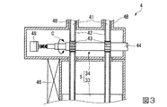
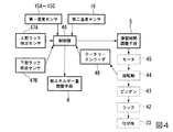
本実施形態における乾燥装置1は、間接乾燥法を採用した乾燥装置であって、図1に示すように、中空の固定体2と、固定体2に対して回転自在に挿通された回転軸3と、この回転軸3の軸方向に連設された複数の撹拌羽根22と、固定体2内の被乾燥物中の水分量を検知する検知手段(第一温度センサ15A〜15C、第二温度センサ16)と、固定体2に設けられて固定体2内部の被乾燥物を排出する被乾燥物排出部4と、被乾燥物排出部4からの被乾燥物の滞留時間を調整する滞留時間調整手段5(図2参照)と、回転軸3に流入する熱媒体の熱エネルギー量を制御する熱エネルギー量調整手段6と、滞留時間調整手段5及び熱エネルギー量調整手段6を制御する制御盤(制御部)46と、を備えている。
Embodiments of the present invention will be described below with reference to the accompanying drawings.
The
ここで、熱媒体の熱エネルギー量とは、例えば熱媒体の温度、圧力、流量等をパラメータとして表されるものであり、被乾燥物の乾燥特性などに応じて適宜パラメータの範囲を設定することができる。なお、本実施形態の乾燥装置1において、熱媒体として、蒸気が使用されている。
Here, the amount of heat energy of the heat medium is expressed by, for example, the temperature, pressure, flow rate, etc. of the heat medium as parameters, and the range of the parameters is appropriately set according to the drying characteristics of the object to be dried. Can do. In the
固定体2は、横置きされて両端に側壁(一方の側壁)11、側壁(他方の側壁)12がそれぞれ設けられた筒状体13と、筒状体13の外周面を覆うように設けられたジャケット23とを備えている。
筒状体13は、円筒形状であり、側壁11側の上面に被乾燥物を供給する被乾燥物導入口13Aが設けられており、側壁12側に筒状体13内を移送された被乾燥物を排出する被乾燥物排出部4が設けられている。ここで、被乾燥物導入口13Aは、側壁11よりも若干側壁12側に設けられている。また、被乾燥物は筒状体内を矢印W方向に移送される。
The fixed
The
また、筒状体13には、上側の内周面から回転軸3の軸心に向かって固定板14が複数設けられている。これら複数の固定板14は、後述する複数の撹拌羽根22の間にそれぞれ突出するように設けられている。
さらに、筒状体13の内部には、図2に示すように、筒状体13内部の被乾燥物の温度を検出する1又は複数の第一温度センサ(第一検知手段)15A〜15Cが設けられている。なお、第一温度センサ15Cは、筒状体13の被乾燥物排出部4近傍の内周面に設けられている。
The
Furthermore, as shown in FIG. 2, one or more first temperature sensors (first detection means) 15 </ b> A to 15 </ b> C for detecting the temperature of the object to be dried inside the
この第一温度センサ15A〜15Cは、筒状体13内部の被乾燥物の温度の検出結果を、後述する制御盤46に通知できるように構成されている。なお、第一温度センサは、3つ配置されており、本実施形態においては、3つのセンサ(第一温度センサ15A、15B、15C)のうちから第一温度センサ15Cを選択して温度の検出結果が制御盤46に通知されるようになっている。
ジャケット23は、蒸気導入口23Aから蒸気(熱媒体)が導入され、ジャケット23内を流通した蒸気が蒸気排出口23Bから排出されるようになっている。
The first temperature sensors 15 </ b> A to 15 </ b> C are configured to notify the
The
ここで、本実施形態において、筒状体13の被乾燥物導入口13Aが設けられた側の一端を上流端、被乾燥物排出部4が設けられた側の一端を下流端と称する。
また、筒状体13には、被乾燥物を加熱することで発生する水蒸気を排気する水分排気口13B及び筒状体13の内部に空気(キャリアガス)を導入する空気導入口13Cが設けられている。すなわち、被乾燥物から生じる水蒸気は、空気導入口13Cから導入されるキャリアガスによって水分排気口13Bへと運ばれ、筒状体13の外部へ排気される。本実施形態においては、水分排気口13Bの内周面の近傍には、筒状体13から排気される排気ガス(キャリアガス)の温度を検出する第二温度センサ(第二検知手段)16が設けられている。
この第二温度センサ16は、筒状体から排気される排気ガス(キャリアガス)の温度の検出結果を、後述する制御盤46に通知するように構成されている。
本実施形態においては、検知手段は、上述の第一温度センサ15A〜15C、及びこの第二温度センサ16によって構成されている。
Here, in the present embodiment, one end of the
Further, the
The
In the present embodiment, the detection means includes the first temperature sensors 15 </ b> A to 15 </ b> C and the
回転軸3は、固定体2の外部に設けられた動力源(図示略)によって、図1に示す矢印A方向で回転自在となっている。
回転軸3は、円筒形状を有し、その両端部が固定体2の側壁11、12を貫通して延在している。この回転軸3は、固定体2の外部において回転軸3内に熱媒体である蒸気S1を導入するための蒸気導入口3Aが設けられている。この蒸気S1は、回転軸3の内部を流通し、ドレンS2として排出される。
The rotating shaft 3 is rotatable in the direction of arrow A shown in FIG. 1 by a power source (not shown) provided outside the
The rotating shaft 3 has a cylindrical shape, and both end portions thereof extend through the
複数の撹拌羽根22は、筒状体13の内部に供給された被乾燥物との接触面積を増大させるために設けられており、等間隔で配置されている。また、撹拌羽根22は、中空の円盤形状を有しており、回転軸3内を流通する蒸気S1が撹拌羽根22内にも流通可能となっている。
The plurality of stirring
被乾燥物排出部4は、図2及び図3に示すように、筒状体13の周面に連設された中空の箱形状を有しており、移行部31と排出部32とで構成されている。そして、被乾燥物排出部4の内部は、筒状体13から移送された被乾燥物が流通する流路が形成されている。
As shown in FIGS. 2 and 3, the to-be-dried material discharge unit 4 has a hollow box shape continuously provided on the peripheral surface of the
移行部31は、筒状体13の内部と、筒状体13の周面に形成された接続開口13Dを介して接続されており、筒状体13内部の被乾燥物が接続開口13Dから移送される。
排出部32は、移行部31から移送された被乾燥物を被乾燥物排出口4Aから排出する。ここで、移行部31と排出部32との間には、移行部31と排出部32とを接続する流路の堰止め高さを調整する仕切板33が設けられている。
The
The
滞留時間調整手段5は、図2及び図3に示すように、仕切板33と、開閉調整機構34とを備え、これら仕切板33及び開閉調整機構34は、制御盤46により制御されるように構成されている。
As shown in FIGS. 2 and 3, the residence time adjusting means 5 includes a
仕切板33は、図2及び図3に示すように、矩形状の板状部材であって、被乾燥物排出部4内部の幅方向にわたって設けられている。そして、仕切板33は、開閉調整機構34によって被乾燥物排出部4の内部で図2に示す矢印B方向のように、水平面に対して垂直な方向において図2の二点鎖線で示す範囲内で上下移動可能に構成されている。また、仕切板33は、開閉調整機構34によって上方向に移動させると、移行部31と排出部32との間の流路の堰止め高さが高くなり、仕切板33を下方向に移動させると、流路の堰止め高さが低くなるように構成されている。
As shown in FIGS. 2 and 3, the
開閉調整機構34は、被乾燥物排出部4の内部で垂直方向に延在し、水平な方向に間隔をあけて配置された一対のポール41と、ラック42と、一対のピニオン43と、回転軸44と、回転軸44を駆動するモータ45(図4参照)とによって構成されている。なお、モータ45は、制御盤46によって制御される。
The opening /
一対のポール41は、被乾燥物排出部4の上下方向にわたって設けられており、互いに回転軸3の軸方向に沿って間隔をあけて配置されている。そして、ポール41は、上部が被乾燥物排出部4の上部に設けられたポール収容部4Bに収容されている。このポール収容部4Bのいずれか一方の上端部と下端部とには、ラック42が上限または下限に位置していることを検出する上部及び下部ラック検出センサ47A、47Bが設けられている。
これら上部及び下部ラック検出センサ47A、47Bは、ポール収容部4B内の上端部または下端部においてラック42の先端部に設けられた検知板42Aの存在の有無をそれぞれ制御盤46に通知するように構成されている。
The pair of
These upper and lower
ラック42とポール41は、上下に、仕切板33と同様に図2に示す二点鎖線の範囲内で移動可能に構成されており、下方に仕切板33が取り付け固定されている。そして、ラック42とポール41は、上下に移動することで、ポール収容部4B内に設けられた上部及び下部ラック検出センサ47A、47Bによって検出されるように構成されている。
The
ここで、上部ラック検出センサ47Aは、ラック42に伴って上方向に移動する仕切板33が移行部31と排出部32との間の流路を閉状態とするときに、検知板42Aの存在を検出して制御盤46にその旨を通知するように構成されている。
また、下部ラック検出センサ47Bは、仕切板33が流路を全開状態とするときに検知板42Aの存在を検出し、その旨を制御盤46に通知するように構成されている。
Here, the upper
Further, the lower
そして、本実施形態においては、流路を閉状態にするときに、完全に流路が閉じられることはなく、被乾燥物が仕切板33を乗り越えて流通する開口部49が少なくとも形成されるように構成されている。すなわち、仕切板33の高さを最大高さに設定しても、開口部49が形成されるようになっているのである。
なお、この仕切板33の最大高さは、仕切板33の高さを検出する高さ検出センサを移行部31に設けることによって検出するようにし、この高さの検出結果によって、開閉調整機構34により仕切板の高さを制限するようにしても良い。
In the present embodiment, when the flow path is closed, the flow path is not completely closed, and at least an
The maximum height of the
回転軸44は、その軸心が回転軸3の軸心と平行となっており、一対のラック42とそれぞれ噛合する一対のピニオン43が設けられている。そして、回転軸44は、モータ45によって図2及び図3に示す矢印C方向で回転可能となっており、回転することでピニオン43と噛合するラック42とポール41が上下に移動する。また、回転軸44には、回転軸44の回転量を検出するロータリーエンコーダ48が設けられている。このロータリーエンコーダ48は、回転軸44の回転量を制御盤46に通知するように構成されている。
The
熱エネルギー量調整手段6は、蒸気導入口3Aから回転軸3に流入する蒸気S1の熱エネルギー量を調整するものである。熱エネルギー量調整手段6は、例えば、回転軸3に流入する蒸気S1の蒸気供給源における蒸気S1の温度を調整する温度調整器と、流量を調整する流量調整器と、圧力を調整する圧力調整器とを備えている。これら温度調整器、流量量精機、及び圧力調整器は、制御盤46により制御される。
この熱エネルギー量調整手段6によって、蒸気S1の温度、圧力、及び流量を調整することによって蒸気S1の熱エネルギー量を制御する。
The thermal energy amount adjusting means 6 is for adjusting the thermal energy amount of the steam S1 flowing into the rotary shaft 3 from the
The heat energy amount adjusting means 6 controls the amount of heat energy of the steam S1 by adjusting the temperature, pressure, and flow rate of the steam S1.
制御盤46には、供給する被乾燥物の原料の情報や、乾燥処理後における被乾燥物中の所望の水分量に相当する被乾燥物の温度などをあらかじめ入力可能となっている。
また、被乾燥物の温度及び排気ガス(キャリアガス)の温度に対する水分量の相関を記したデータベースがハードディスクドライブなどの記憶媒体(図示なし)に記憶されている。制御盤46は、入力された被乾燥物の原料の情報や第一温度センサ15C及び第二温度センサ16による被乾燥物の温度と排気ガス(キャリアガス)の温度との検出結果から、被乾燥物中の水分量を上述の記憶媒体から読み出すように構成されている。
In the
Further, a database describing the correlation of the moisture content with respect to the temperature of the object to be dried and the temperature of the exhaust gas (carrier gas) is stored in a storage medium (not shown) such as a hard disk drive. The
そして、制御盤46は、第一温度センサ15C及び第二温度センサ16による検出結果から被乾燥物中の水分量を導出し、あらかじめ入力された乾燥処理後の被乾燥物中の水分量と比較する。次いで、この比較に基づいて、被乾燥物の水分量が所望のものとなるように、回転軸44を回転駆動するモータ45に対して回転軸44を回転させて仕切板33による流路の堰止め高さと、回転軸44に流入する蒸気S1の熱エネルギー量(温度、圧力、及び流量)とを制御する。なお、制御盤46は、ロータリーエンコーダ48で検出した回転軸44の回転量の検出結果も参照して、仕切板33による堰止め高さの適正高さ、及び蒸気S1の熱エネルギー量の適正量を判断する。
Then, the
次に、上述の構成を有する乾燥装置1を用いた被乾燥物(処理物)の乾燥方法について説明する。
まず、蒸気導入口3Aから熱媒体である蒸気S1を回転軸3内に導入する。これにより、複数の撹拌羽根22は、内部を流通する蒸気S1によって加熱される。また、ジャケット23にも熱媒体としての蒸気を蒸気導入口23Aから導入することによって筒状体13を加熱する。そして、回転軸3を回転させる。このとき、供給する被乾燥物の原料の情報や乾燥処理後の所望する水分量に相当する被乾燥物の温度を、制御盤46に入力する。
Next, a method for drying an object to be dried (processed object) using the
First, the steam S1, which is a heat medium, is introduced into the rotating shaft 3 from the
そして、被乾燥物導入口13Aから被乾燥物を供給する。供給された被乾燥物は、筒状体13の下側の内周面上に載置され、回転軸3が回転することによって上流側から下流側に向けて送り出される。このとき、被乾燥物は、蒸気によって加熱された回転軸3及び撹拌羽根22や筒状体13のジャケット23内周面に被乾燥物が接触することで被乾燥物中の水分が蒸発して乾燥される。また、被乾燥物を乾燥することで被乾燥物から発生した水蒸気などは、筒状体13の内部を流れる空気(キャリアガス)と混合されて、水分排気口13Bから排気ガスとして固定体2の外部に排出される。
Then, the material to be dried is supplied from the material to be dried
接続開口13D近傍まで移送された被乾燥物は、撹拌羽根22が回転することによって筒状体13の内周面に沿って持ち上げられ、筒状体13の内部から被乾燥物排出部4の移行部31に移送される。そして、移送された被乾燥物は、仕切板33を乗り越えるようにして移行部31から排出部32に移送され、被乾燥物排出口4Aから排出される。
The to-be-dried material transferred to the vicinity of the
被乾燥物が筒状体13内部で撹拌、乾燥されながら下流に向かって移送される間に、筒状体13の内周面であって被乾燥物排出部4の近傍に設けられた第一温度センサ15A〜15Cは、筒状体13内部の被乾燥物の温度を検出し、この検出結果を制御盤46に通知する。ここで、第一温度センサ15A〜15Cの3つの温度センサのうちから選択して用いることができ、本実施形態においては、3つのうち第一温度センサ15を選択している。
また、被乾燥物が下流に向かって移送される間に、水分排気口13Bの内周面の近傍に設けられた第二温度センサ16は、排気ガスの温度を検出し、この検出結果を制御盤46に通知する。
A first object provided on the inner peripheral surface of the
Further, while the material to be dried is transferred downstream, the
そして、制御盤46は、入力された被乾燥物の原料の情報や、第一温度センサ15C及び第二温度センサ16によって検出した温度から筒状体13内部の被乾燥物中の水分量を、前述のデータベースを参照して算出し、入力された乾燥処理後の所望する水分量とデータベースから算出した被乾燥物中の水分量とを比較する。
なお、筒状体13内部で被乾燥物がある程度乾燥された状態では、被乾燥物中の水分量と被乾燥物の温度との間に相関性を有しているので、被乾燥物の温度から被乾燥物中の水分量を導出することができる。
And the
In addition, in the state in which the to-be-dried object was dried to some extent inside the
ここで、制御盤46が算出した被乾燥物の水分量が所望の水分量に比較してずれている場合には、滞留時間調整手段5と、熱エネルギー量調整手段6とを併せて制御し、被乾燥物の水分量を所望の水分量に調整する。
より具体的には、制御盤46が算出した被乾燥物中の水分量が所望の水分量よりも高いと判断した場合には、回転軸44が所定の回転数だけ回転するようにモータ45を駆動し、仕切板33をポール41に沿って上方向に移動させるととともに、蒸気S1の温度、圧力、及び流量を高く設定して蒸気S1の熱エネルギー量を大きく設定する。
Here, when the moisture content of the material to be dried calculated by the
More specifically, when it is determined that the moisture content in the material to be dried calculated by the
ここで、制御盤46は、ロータリーエンコーダ48で検出される回転軸44の回転量の検出結果に基づいて、仕切板33による堰止め高さを決定し、仕切板33を所定の高さに制御している。
なお、制御盤46は、上部ラック検出センサ47Aが検知板42Aの存在を検出したとき、回転軸44の回転中に流路が仕切板33によって閉状態となったと判断し、回転軸44の回転を停止させる。また、本実施形態では、この仕切板33の高さが、最大高さに設定されても、開口部49が形成されるようになっている。
Here, the
When the upper
仕切板33を上方向に移動させると、仕切板33による被乾燥物排出部4の流路の堰止め高さが高くなるので、移行部31に移送された被乾燥物が仕切板33を乗り越えにくくなる。したがって、被乾燥物が投入されてから排出されるまで、筒状体13の内部に長時間滞留して、被乾燥物に対する乾燥時間が長くなる。これにより、筒状体13の内部に滞留している被乾燥物は、回転軸3及び撹拌羽根22や筒状体13のジャケット23内周面と接触することで加熱され、被乾燥物中の水分が蒸発し、より乾燥される。
このような堰止め高さの調整時においても、第一温度センサ15C及び第二温度センサ16は、筒状体13内部の被乾燥物の温度、及び排気ガスの温度を検出し、検出結果を制御盤46に通知する。
When the
Even when the height of the weir is adjusted, the
また、蒸気S1の温度、圧力、及び流量を高く設定すると、回転軸3及び撹拌羽根22の加熱温度が高くなり、これら回転軸3及び撹拌羽根22に接触する被乾燥物に与えられる熱が大きくなり、被乾燥物中の水分が蒸発し、より速く乾燥される。
なお、この蒸気S1の温度、圧力、流量の調整時においても、第一温度センサ15C及び第二温度センサ16は、筒状体13内部の被乾燥物の温度、及び排気ガスの温度を検出し、検出結果を制御盤46に通知する。
Further, when the temperature, pressure, and flow rate of the steam S1 are set high, the heating temperature of the rotating shaft 3 and the
Even when adjusting the temperature, pressure, and flow rate of the steam S1, the
一方、制御盤46が算出した被乾燥物中の水分量が所望の水分量よりも低いと判断した場合には、回転軸44が所定の回転数だけ回転するようにモータ45を駆動し、仕切板33をポール41に沿って下方向に移動させるととともに、蒸気S1の温度、圧力、及び流量を低く設定して蒸気S1の熱エネルギー量を小さく設定する。
なお、制御盤46は、上述と同様に、下部ラック検出センサ47Bが検知板42Aの存在を検出したとき、回転軸44の回転中に流路が仕切板33によって全開状態となったと判断し、回転軸44の回転を停止させる。
On the other hand, when it is determined that the moisture content in the material to be dried calculated by the
As described above, the
仕切板33を下方向に移動させると、仕切板33による被乾燥物排出部4の流路の堰止め高さが低くなるので、移行部31に移送された被乾燥物が仕切板33を乗り越えやすくなる。したがって、被乾燥物が筒状体13から被乾燥物排出部4に向けて移送されやすくなって筒状体13内部での滞留時間が短くなる。また、筒状体13内部の被乾燥物に対する乾燥時間が短くなる。
さらに、蒸気S1の温度、圧力、及び流量を低く設定すると、回転軸3及び撹拌羽根22の温度が低くなり、これら回転軸3及び撹拌羽根22及び筒状体13のジャケット23に接触する被乾燥物に接触する被乾燥物に与えられる熱が小さくなるので、被乾燥物中の水分の蒸発が少なくなり、被乾燥物の水分量が所望の水分量に近づく。
When the
Furthermore, when the temperature, pressure, and flow rate of the steam S1 are set low, the temperature of the rotating shaft 3 and the
以上のように、第一温度センサ15C及び第二温度センサ16の検出結果から、筒状体13内部の被乾燥物の水分量を導出し、この導出した水分量の結果に基づいて、仕切板33による堰止め高さと、蒸気S1の温度、圧力、及び流量を調整して被乾燥物の乾燥時間を制御しながら、被乾燥物を乾燥する。なお、第一温度センサ15A〜15Cの3つの温度センサから検出される温度を制御盤46に通知する場合には、例えば3つの温度センサの平均値の温度に基づいて筒状体13内部の被乾燥物の水分量を導出すれば良い。
As described above, the moisture content of the material to be dried inside the
以上のような構成とされた本実施形態に係る乾燥装置1によれば、筒状体13内部の被乾燥物の水分量を導出し、この水分量から仕切板33の高さを制御して被乾燥物の滞留時間と調整するとともに、回転軸3を流れる熱媒体の熱エネルギー量を制御盤46により制御することで、被乾燥物の水分量を調整することができる。さらに、水分量のバラつきが小さい被乾燥物を安定して排出し、かつ効率的に乾燥させることが可能である。
According to the
さらに、本実施形態においては、被乾燥物の温度と排気ガスの温度とによって、被乾燥物の水分量を導出し、この導出した水分量に応じて、被乾燥物が筒状体13の内部に滞留する時間、及び蒸気S1の温度、圧力、及び流量を調整する構成とされているので、滞留時間及び熱媒体のエネルギー量をより適正に制御することができ、さらに被乾燥物の水分量のバラつきを低減することが可能となる。
Furthermore, in this embodiment, the moisture content of the material to be dried is derived based on the temperature of the material to be dried and the temperature of the exhaust gas, and the material to be dried is inside the
また、本実施形態では、仕切板33の堰止め高さが最大に設定されても開口部49が形成されるので、被乾燥物が筒状体13の内部に溜まることを防止し、被乾燥物を確実に流通させ、仕切板33に過負荷がかかることを防止できる。また、多量の被乾燥物が一度に被乾燥物排出部4に流通することを防止し、被乾燥物が被乾燥物排出部4に詰まることを防止することもできる。
Further, in this embodiment, the
さらに、本実施形態では、回転軸3及び撹拌羽根22の内部を流通する蒸気S1とジャケット23を流通する蒸気の双方の熱によって効率的かつ速やかに被乾燥物を乾燥することができる。
Furthermore, in the present embodiment, the material to be dried can be efficiently and quickly dried by the heat of both the steam S1 flowing through the rotary shaft 3 and the
以上、本発明の実施形態について説明したが、本発明は上記実施形態に限定されるものではなく、本発明の趣旨を逸脱しない範囲において種々の変更を加えることができる。 As mentioned above, although embodiment of this invention was described, this invention is not limited to the said embodiment, A various change can be added in the range which does not deviate from the meaning of this invention.
例えば、上記実施形態では、乾燥装置1に設けられた第一温度センサ15C(第一検知手段)及び第二温度センサ16(第二検知手段)の検知結果から被乾燥物の水分量を導出したが、第一温度センサ15A〜15Cのうちのいずれかのセンサ又は第二温度センサのみの検知手段によって被乾燥物の水分量を導出しても良い。
For example, in the above embodiment, the moisture content of the material to be dried is derived from the detection results of the
また、上記実施形態では、熱媒体として蒸気を用いて温度、圧力、及び流量を調整することで熱エネルギー量を調整する場合について説明したが、温度、圧力、及び流量のいずれか一つを調整する構成とされても良い。
また、上記実施形態では、熱媒体として蒸気を用いたが、熱媒油や温水など他の熱媒体を用いてもよい。
また、上記実施形態では、回転軸及び撹拌羽根の内部を流入する熱媒体の熱エネルギー量を調整する場合について説明したが、ジャケットの内部を流れる熱エネルギー量も同時に調整する構成とされても良い。
In the above embodiment, the case where the heat energy amount is adjusted by adjusting the temperature, pressure, and flow rate using steam as the heat medium has been described. However, any one of the temperature, pressure, and flow rate is adjusted. It may be configured to.
Moreover, in the said embodiment, although steam was used as a heat medium, you may use other heat media, such as heat-medium oil and warm water.
Moreover, although the said embodiment demonstrated the case where the amount of thermal energy of the heat medium which flows in into the inside of a rotating shaft and a stirring blade was demonstrated, it may be set as the structure which also adjusts the amount of thermal energy which flows through the inside of a jacket simultaneously. .
また、第一検知手段として第一温度センサ15A〜15Cを用いたが、例えば、筒状体13内の湿度を検出する湿度検出センサや、水分を検出する水分検出センサなど、他のセンサを用いてもよい。
また。本実施形態においては、第一温度センサは、3つ配置されている場合について説明したが、少なくとも一つ以上配置されていれば良い。
Moreover, although the
Also. In this embodiment, although the case where three 1st temperature sensors are arrange | positioned was demonstrated, at least 1 or more should just be arrange | positioned.
また、制御盤46が被乾燥物中の水分量をデータベースが記憶された記憶媒体から読み出すように構成されているが、被乾燥物の原料と、第一温度センサ又は第二温度センサによる温度の検出結果とから被乾燥物中の水分量を演算して導出するように構成してもよい。
また、筒状体13の内周面に固定板14が設けられているが、固定板14を設けない構成としてもよい。
In addition, the
Further, although the fixed
1 乾燥装置
2 固定体
3 回転軸
4 被乾燥物排出部
5 滞留時間調整手段
6 熱エネルギー量調整手段
13 筒状体
15A、15B、15C 第一温度センサ(第一検知手段)
16 第二温度センサ(第二検知手段)
22 撹拌羽根
33 仕切板
34 開閉調整機構
46 制御盤(制御部)
DESCRIPTION OF
16 Second temperature sensor (second detection means)
22
Claims (7)
前記筒状体内の前記被乾燥物中の水分量を検知する検知手段と、
前記被乾燥物の滞留時間を調整する滞留時間調整手段と、
前記熱媒体の熱エネルギー量を調整する熱エネルギー量調整手段と、
前記滞留時間調整手段及び前記熱エネルギー量調整手段を制御する制御部と、を備え、
前記検知手段により検知される前記被乾燥物の水分量に応じて、前記滞留時間調整手段と、前記熱エネルギー量調整手段とを前記制御部により制御することを特徴とする乾燥装置。 A fixed body having a cylindrical body with side walls provided at both ends, a rotating shaft rotatably inserted in the fixed body, and a plurality of stirring blades connected in the axial direction of the rotating shaft, The rotating shaft and the stirring blade are supplied with a heat medium that circulates inside, and the object to be dried supplied to the cylindrical body is directed toward the object to be dried provided in the fixed body. A drying device that heats and dries while transporting in the axial direction,
Detecting means for detecting the amount of water in the material to be dried in the cylindrical body;
A residence time adjusting means for adjusting the residence time of the material to be dried;
A heat energy amount adjusting means for adjusting a heat energy amount of the heat medium;
A control unit for controlling the residence time adjusting means and the thermal energy amount adjusting means,
The drying apparatus, wherein the dwell time adjusting unit and the thermal energy amount adjusting unit are controlled by the control unit in accordance with a moisture content of the object to be dried detected by the detecting unit.
前記被乾燥物の水分量に応じて前記仕切板の堰止め高さを調整し、前記仕切板を乗り越えるように前記被乾燥物を流通させる開閉調整機構と、
を備えることを特徴とする請求項1に記載の乾燥装置。 The residence time adjusting means is a partition plate that is formed in the dry matter discharge section and prevents the dry matter that has been transferred from the cylindrical body;
An opening / closing adjustment mechanism that adjusts the weir height of the partition plate according to the moisture content of the material to be dried, and distributes the material to be dried so as to get over the partition plate;
The drying apparatus according to claim 1, comprising:
前記筒状体の内部を流通し前記被乾燥物から生じる水蒸気を含んで外部へ排気される排気ガスの温度を測定し、該温度に基づいて前記被乾燥物の水分量を導出することを特徴とする請求項1から請求項3のいずれか一項に記載の乾燥装置。 The detection means is
Measuring the temperature of exhaust gas that flows through the cylindrical body and exhausts to the outside including water vapor generated from the object to be dried, and derives the moisture content of the object to be dried based on the temperature. The drying apparatus according to any one of claims 1 to 3.
前記筒状体内部に供給された前記被乾燥物の温度を測定する第一検知手段と、
前記筒状体の内部を流通し前記被乾燥物から生じる水蒸気を含んで外部へ排気される排気ガスの温度を測定する第二検知手段と、からなり、
前記第一検知手段によって測定される前記被乾燥物の温度と、前記第二検知手段によって測定される前記排気ガスの温度と、に基づいて前記被乾燥物の水分量を導出することを特徴とする請求項1から請求項3のいずれか一項に記載の乾燥装置。 The detection means is
First detection means for measuring the temperature of the material to be dried supplied into the cylindrical body;
A second detection means for measuring the temperature of the exhaust gas that flows through the cylindrical body and contains water vapor generated from the material to be dried and exhausted to the outside, and
Deriving the moisture content of the object to be dried based on the temperature of the object to be dried measured by the first detection means and the temperature of the exhaust gas measured by the second detection means; The drying apparatus according to any one of claims 1 to 3.
前記熱媒体の温度、圧力、及び流量の少なくともいずれか一つを制御することによって前記熱エネルギー量を調整することを特徴とする請求項1から請求項6のいずれか一項に記載の乾燥装置。 The heat medium is any one selected from steam, heat medium oil, and hot water,
The drying apparatus according to any one of claims 1 to 6, wherein the amount of heat energy is adjusted by controlling at least one of temperature, pressure, and flow rate of the heat medium. .
Priority Applications (1)
| Application Number | Priority Date | Filing Date | Title |
|---|---|---|---|
| JP2013138851A JP6233955B2 (en) | 2013-07-02 | 2013-07-02 | Drying equipment |
Applications Claiming Priority (1)
| Application Number | Priority Date | Filing Date | Title |
|---|---|---|---|
| JP2013138851A JP6233955B2 (en) | 2013-07-02 | 2013-07-02 | Drying equipment |
Publications (2)
| Publication Number | Publication Date |
|---|---|
| JP2015010809A true JP2015010809A (en) | 2015-01-19 |
| JP6233955B2 JP6233955B2 (en) | 2017-11-22 |
Family
ID=52304118
Family Applications (1)
| Application Number | Title | Priority Date | Filing Date |
|---|---|---|---|
| JP2013138851A Active JP6233955B2 (en) | 2013-07-02 | 2013-07-02 | Drying equipment |
Country Status (1)
| Country | Link |
|---|---|
| JP (1) | JP6233955B2 (en) |
Cited By (5)
| Publication number | Priority date | Publication date | Assignee | Title |
|---|---|---|---|---|
| WO2016201665A1 (en) * | 2015-06-18 | 2016-12-22 | 张甘霖 | Rotary drying device |
| JP2018109454A (en) * | 2016-12-28 | 2018-07-12 | 綜研テクニックス株式会社 | Rotary disc-type dryer |
| CN109282605A (en) * | 2018-12-07 | 2019-01-29 | 徐州龙豪新能源科技有限公司 | Biomass fuel drying unit |
| JP2021014927A (en) * | 2019-07-10 | 2021-02-12 | 水ing株式会社 | Drying facility and heating amount control method |
| JP2021014926A (en) * | 2019-07-10 | 2021-02-12 | 水ing株式会社 | Drying facility and heating amount control method |
Citations (4)
| Publication number | Priority date | Publication date | Assignee | Title |
|---|---|---|---|---|
| JPH03137998A (en) * | 1989-10-24 | 1991-06-12 | Tsukishima Kikai Co Ltd | Sludge dry controlling method |
| JP2003222470A (en) * | 2002-01-28 | 2003-08-08 | Sumitomo Chem Co Ltd | Temperature control device for dryer, dryer having the same, and drying method of drying object |
| JP2006349316A (en) * | 2005-06-20 | 2006-12-28 | Mitsubishi Materials Techno Corp | Drier |
| JP2012202673A (en) * | 2011-03-28 | 2012-10-22 | Yasujima:Kk | Heat treatment wooden material producing device utilizing superheated vapor and heat treatment wooden material producing method |
-
2013
- 2013-07-02 JP JP2013138851A patent/JP6233955B2/en active Active
Patent Citations (4)
| Publication number | Priority date | Publication date | Assignee | Title |
|---|---|---|---|---|
| JPH03137998A (en) * | 1989-10-24 | 1991-06-12 | Tsukishima Kikai Co Ltd | Sludge dry controlling method |
| JP2003222470A (en) * | 2002-01-28 | 2003-08-08 | Sumitomo Chem Co Ltd | Temperature control device for dryer, dryer having the same, and drying method of drying object |
| JP2006349316A (en) * | 2005-06-20 | 2006-12-28 | Mitsubishi Materials Techno Corp | Drier |
| JP2012202673A (en) * | 2011-03-28 | 2012-10-22 | Yasujima:Kk | Heat treatment wooden material producing device utilizing superheated vapor and heat treatment wooden material producing method |
Cited By (6)
| Publication number | Priority date | Publication date | Assignee | Title |
|---|---|---|---|---|
| WO2016201665A1 (en) * | 2015-06-18 | 2016-12-22 | 张甘霖 | Rotary drying device |
| JP2018109454A (en) * | 2016-12-28 | 2018-07-12 | 綜研テクニックス株式会社 | Rotary disc-type dryer |
| CN109282605A (en) * | 2018-12-07 | 2019-01-29 | 徐州龙豪新能源科技有限公司 | Biomass fuel drying unit |
| JP2021014927A (en) * | 2019-07-10 | 2021-02-12 | 水ing株式会社 | Drying facility and heating amount control method |
| JP2021014926A (en) * | 2019-07-10 | 2021-02-12 | 水ing株式会社 | Drying facility and heating amount control method |
| JP7304227B2 (en) | 2019-07-10 | 2023-07-06 | 水ing株式会社 | Drying equipment and heating amount control method |
Also Published As
| Publication number | Publication date |
|---|---|
| JP6233955B2 (en) | 2017-11-22 |
Similar Documents
| Publication | Publication Date | Title |
|---|---|---|
| JP6233955B2 (en) | Drying equipment | |
| JP2006349316A (en) | Drier | |
| KR100424512B1 (en) | Wood drying equipment | |
| EP2447655B1 (en) | Method and plant for dehumidifying material in granular form | |
| AU2007307805A1 (en) | Apparatus, method and system for treating sewage sludge | |
| JPH0532991U (en) | Drying device for powder | |
| TW201211481A (en) | Indirectly heated rotary dryer | |
| JP2019076021A (en) | Tea leaf drying apparatus, and tea leaf drying method by the same | |
| US20170051974A1 (en) | Infrared drying system for wet organic solids | |
| CN104034127A (en) | Microwave-hot air combined fluidized bed drying experiment device | |
| JP2016006371A (en) | Drier and drying system | |
| JP5635952B2 (en) | Drying equipment | |
| KR102512498B1 (en) | Sludge drying apparatus | |
| JP2006007025A (en) | Drier | |
| JP2007205652A (en) | Drying method and fluid drier for object to be dried | |
| KR20200012232A (en) | Sludge drying apparatus | |
| KR101270654B1 (en) | Electric dryer | |
| JP4633216B2 (en) | Carbonization method with screw-type carbonization furnace | |
| KR101287853B1 (en) | Drying apparatus for for vacuum freezing drier | |
| US10969170B2 (en) | Dynamic state configuration for paddle processor | |
| KR100857077B1 (en) | Complex refractance dryer | |
| JP6396149B2 (en) | Operation method of drying equipment | |
| JP2011033224A (en) | Method of operating horizontal continuous conduction heat transfer type dryer | |
| CZ20031549A3 (en) | Apparatus for purification and/or decontamination of polyester | |
| JP5616052B2 (en) | Processing equipment |
Legal Events
| Date | Code | Title | Description |
|---|---|---|---|
| A621 | Written request for application examination |
Free format text: JAPANESE INTERMEDIATE CODE: A621 Effective date: 20160527 |
|
| A977 | Report on retrieval |
Free format text: JAPANESE INTERMEDIATE CODE: A971007 Effective date: 20170125 |
|
| A131 | Notification of reasons for refusal |
Free format text: JAPANESE INTERMEDIATE CODE: A131 Effective date: 20170214 |
|
| A521 | Request for written amendment filed |
Free format text: JAPANESE INTERMEDIATE CODE: A523 Effective date: 20170414 |
|
| TRDD | Decision of grant or rejection written | ||
| A01 | Written decision to grant a patent or to grant a registration (utility model) |
Free format text: JAPANESE INTERMEDIATE CODE: A01 Effective date: 20170926 |
|
| A61 | First payment of annual fees (during grant procedure) |
Free format text: JAPANESE INTERMEDIATE CODE: A61 Effective date: 20171023 |
|
| R150 | Certificate of patent or registration of utility model |
Ref document number: 6233955 Country of ref document: JP Free format text: JAPANESE INTERMEDIATE CODE: R150 |
|
| R250 | Receipt of annual fees |
Free format text: JAPANESE INTERMEDIATE CODE: R250 |
|
| R250 | Receipt of annual fees |
Free format text: JAPANESE INTERMEDIATE CODE: R250 |
|
| R250 | Receipt of annual fees |
Free format text: JAPANESE INTERMEDIATE CODE: R250 |
|
| R250 | Receipt of annual fees |
Free format text: JAPANESE INTERMEDIATE CODE: R250 |