JP2015007902A - Road state grasping system and road state grasping apparatus - Google Patents
Road state grasping system and road state grasping apparatus Download PDFInfo
- Publication number
- JP2015007902A JP2015007902A JP2013132950A JP2013132950A JP2015007902A JP 2015007902 A JP2015007902 A JP 2015007902A JP 2013132950 A JP2013132950 A JP 2013132950A JP 2013132950 A JP2013132950 A JP 2013132950A JP 2015007902 A JP2015007902 A JP 2015007902A
- Authority
- JP
- Japan
- Prior art keywords
- vehicle
- road
- distance
- inter
- calculating
- Prior art date
- Legal status (The legal status is an assumption and is not a legal conclusion. Google has not performed a legal analysis and makes no representation as to the accuracy of the status listed.)
- Granted
Links
Images


Classifications
-
- G—PHYSICS
- G08—SIGNALLING
- G08G—TRAFFIC CONTROL SYSTEMS
- G08G1/00—Traffic control systems for road vehicles
- G08G1/01—Detecting movement of traffic to be counted or controlled
- G08G1/0104—Measuring and analyzing of parameters relative to traffic conditions
- G08G1/0125—Traffic data processing
- G08G1/0133—Traffic data processing for classifying traffic situation
-
- G—PHYSICS
- G06—COMPUTING; CALCULATING OR COUNTING
- G06V—IMAGE OR VIDEO RECOGNITION OR UNDERSTANDING
- G06V20/00—Scenes; Scene-specific elements
- G06V20/50—Context or environment of the image
- G06V20/52—Surveillance or monitoring of activities, e.g. for recognising suspicious objects
- G06V20/54—Surveillance or monitoring of activities, e.g. for recognising suspicious objects of traffic, e.g. cars on the road, trains or boats
-
- G—PHYSICS
- G08—SIGNALLING
- G08G—TRAFFIC CONTROL SYSTEMS
- G08G1/00—Traffic control systems for road vehicles
- G08G1/01—Detecting movement of traffic to be counted or controlled
- G08G1/0104—Measuring and analyzing of parameters relative to traffic conditions
- G08G1/0108—Measuring and analyzing of parameters relative to traffic conditions based on the source of data
- G08G1/0112—Measuring and analyzing of parameters relative to traffic conditions based on the source of data from the vehicle, e.g. floating car data [FCD]
Landscapes
- Physics & Mathematics (AREA)
- General Physics & Mathematics (AREA)
- Engineering & Computer Science (AREA)
- Chemical & Material Sciences (AREA)
- Analytical Chemistry (AREA)
- Multimedia (AREA)
- Theoretical Computer Science (AREA)
- Traffic Control Systems (AREA)
- Image Processing (AREA)
- Image Analysis (AREA)
Abstract
Description
本発明の実施形態は、道路状況把握システム、及び道路状況把握装置に関する。 Embodiments described herein relate generally to a road condition grasping system and a road condition grasping apparatus.
従来、高度交通システム(Intelligent Transport Systems:ITS)では、渋滞や混雑などの道路状況の把握が行われている。この道路状況の把握には、路側に設置したカメラなどの路側装置の検出結果を用いる方法がある。また、車両にGPS(Global Positioning System)装置を搭載し、GPS装置から得られる位置情報と、車両の速度計から得られる速度情報とを用いる方法がある。 Conventionally, in intelligent transport systems (ITS), road conditions such as traffic congestion and congestion have been grasped. For grasping the road condition, there is a method of using a detection result of a roadside device such as a camera installed on the roadside. In addition, there is a method in which a GPS (Global Positioning System) device is mounted on a vehicle and position information obtained from the GPS device and speed information obtained from a vehicle speedometer are used.
しかしながら、上述した従来技術では、路側装置を設置した地点の道路状況が把握できるだけであり、数多くの地点の道路状況を把握するための設置コストが高かった。また、ある車線を走行する車両の速度と位置だけでは、車両が過密な状態であるか否かなどの、より正確な道路状況を把握することは困難であった。 However, in the above-described prior art, it is only possible to grasp the road situation at the point where the roadside device is installed, and the installation cost for grasping the road situation at many points is high. In addition, it is difficult to grasp a more accurate road condition such as whether the vehicle is overcrowded only by the speed and position of the vehicle traveling in a certain lane.
上述した課題を解決するために、実施形態の道路状況把握システムは、車両に搭載される車載装置と、当該車載装置から送信される情報を処理する情報処理装置とを備える道路状況把握システムであって、前記車載装置は、前記車両の位置を検出する位置検出手段と、前記車両の周囲を撮像する撮像手段と、前記撮像手段により撮像された画像をもとに、他の車両との車間距離を算出する車間距離算出手段と、前記算出された車間距離と、前記検出された車両の位置とに基づいて、当該位置を走行する車両の密度を算出する車両密度算出手段と、前記検出された車両の位置と、前記算出された車両の密度とを含む道路情報を前記情報処理装置へ送信する送信手段と、を備え、前記情報処理装置は、前記送信された道路情報をもとに、前記車両が走行した経路における道路情報を集計して前記経路の混雑具合を示す道路状況を算出する道路状況算出手段を備える。 In order to solve the above-described problems, a road situation grasping system according to an embodiment is a road situation grasping system including an in-vehicle device mounted on a vehicle and an information processing device that processes information transmitted from the in-vehicle device. The vehicle-mounted device includes a position detection unit that detects a position of the vehicle, an imaging unit that captures an image of the surroundings of the vehicle, and an inter-vehicle distance from another vehicle based on an image captured by the imaging unit. Based on the calculated inter-vehicle distance and the detected vehicle position, the vehicle density calculating means for calculating the density of the vehicle traveling at the position, and the detected Transmission means for transmitting road information including the position of the vehicle and the calculated density of the vehicle to the information processing apparatus, and the information processing apparatus, based on the transmitted road information, vehicle Running the aggregates the road information in the route includes a road condition calculating means for calculating the road condition indicating a degree of congestion of the route.
また、実施形態の道路状況把握装置は、車両の周囲を撮像する撮像手段と、前記車両の位置を検出する位置検出手段と、前記撮像手段により撮像された画像をもとに、他の車両との車間距離を算出する車間距離算出手段と、前記算出された車間距離と、前記検出された車両の位置とに基づいて、当該位置を走行する車両の密度を算出する車両密度算出手段と、前記検出された車両の位置に基づいた前記車両が走行した経路における、前記算出された車両の密度を集計して、前記経路の混雑具合を示す道路状況を算出する道路状況算出手段と、を備える。 The road condition grasping device according to the embodiment includes an imaging unit that captures an image of the surroundings of the vehicle, a position detection unit that detects the position of the vehicle, and another vehicle based on an image captured by the imaging unit. An inter-vehicle distance calculating means for calculating an inter-vehicle distance, a vehicle density calculating means for calculating a density of a vehicle traveling at the position based on the calculated inter-vehicle distance and the detected position of the vehicle, Road condition calculation means for calculating a road condition indicating the degree of congestion of the route by aggregating the calculated density of the vehicle on the route traveled by the vehicle based on the detected position of the vehicle.
以下、添付図面を参照して実施形態にかかる道路状況把握システム、及び道路状況把握装置を詳細に説明する。なお、以下で説明する実施形態及びその変形例において、同様の構成要素には共通の符号を付与するとともに、重複する説明を省略する。 Hereinafter, a road situation grasping system and a road situation grasping apparatus according to embodiments will be described in detail with reference to the accompanying drawings. Note that, in the embodiment described below and its modifications, common constituent elements are given common reference numerals, and redundant description is omitted.
(第1の実施形態)
図1は、第1の実施形態にかかる道路状況把握システム1の概要を示す概念図である。図1に示すように、道路状況把握システム1は、車両V1に搭載される車載端末20と、車載端末20から送信される道路情報を処理する管理装置10とを備える構成である。
(First embodiment)
FIG. 1 is a conceptual diagram showing an outline of a road
車両V1には、ステレオカメラ21と、GPS装置22とを有する車載端末20が設けられている。ステレオカメラ21は、車両V1の周囲を異なる複数の方向から撮像する複数のデジタルカメラであり、撮像した画像データを車載端末20へ出力する。本実施形態では、左右1対のステレオカメラ21が車両V1の前方上部に設置されているものとする。したがって、ステレオカメラ21によって車両V1の進行方向に沿った前方を左右から撮像した画像(ステレオ画像)が得られることとなる。なお、ステレオカメラ21の設置位置、設置数については、本実施形態の限りではない。例えば、ステレオカメラ21の設置位置を車両V1の後方上部としてもよい。ステレオカメラ21の設置位置が車両V1の後方上部である場合は、車両V1の進行方向に沿った後方のステレオ画像が得られることとなる。
The vehicle V1 is provided with an in-
車載端末20は、ステレオカメラ21によるステレオ画像から車両V1の周囲にあり、車両V1の進行方向に沿った方向、すなわち車両V1が走行する道路上にある車両V2との車間距離を算出する。そして、車載端末20は、算出された車間距離をもとに、道路における車両(V1、V2、…)の密度を算出し、その車両の密度と、GPS装置22により検出される車両V1の現在位置とを含む道路情報を管理装置10へ送信する。
The in-
なお、車載端末20を搭載する車両V1は、決まった路線を定期的に運行する路線バスの他、タクシー、集配車、一般の乗用車などの何れの車種であってよい。本実施形態では、車載端末20は、路線バスに搭載されているものとする。車載端末20を路線バスに搭載する場合には、タクシーや一般の乗用車などと比べて車高が高く、ステレオカメラ21をより高い位置に設置できることから、ステレオカメラ21によるステレオ画像から車両V1の周囲を把握する上で有利である。また、決まった路線に沿った道路情報を定期的に収集できる。また、運行指令所等と通信を行う業務用無線を介した道路情報の収集を行うことが可能となり、車載端末20と管理装置10とを結ぶ通信インフラを新たに用意する必要がない。
The vehicle V1 on which the in-
管理装置10は、PC(Personal Computer)などであり、車載端末20から送信された道路情報を集計して、管理装置10が移動した経路の混雑具合を示す道路状況を算出する。
The
ここでいう道路状況とは、道路における車両の混み具合であり、路面状態(雨濡れ、積雪、凍結等)などの道路の態様は含まないものとする。また、道路情報に含まれる車両の密度は、道路における混雑具合に相当する。すなわち、車両の密度が高ければ混雑していることを示し、車両の密度が低ければ空いていることを示している。 The road condition mentioned here is the degree of crowded vehicles on the road, and does not include road aspects such as road surface conditions (rain wetness, snow accumulation, freezing, etc.). The density of vehicles included in the road information corresponds to the degree of congestion on the road. That is, if the density of the vehicle is high, it is congested, and if the density of the vehicle is low, it is empty.
管理装置10では、車両V1の現在位置とともに逐次送られてくる車両の密度を、車両V1の位置情報をもとに車両V1が走行した経路に沿って集計していくことで、その経路における道路状況を算出する。なお、管理装置10が算出する道路状況は、車両の密度に対応した混雑具合を数値化したものであってもよいし、車両の密度が示す混雑具合を所定の閾値で区切った混雑の段階(例えば「渋滞」、「混雑」、「通常」等)であってもよい。
The
管理装置10は、算出した道路状況を、渋滞の発生場所などを示す地図として出力する。具体的には、管理装置10は、道路や建物の位置が記述された地図情報M1に、車載端末20を搭載した車両V1が走行した経路に沿って算出した道路状況G1、G2、G3を重畳した地図をディスプレイに表示して管理装置10を操作するユーザ(オペレータ等)に通知する。この地図上に表示する道路状況G1、G2、G3は、オペレータが混雑具合を認識しやすいように、混雑具合に応じて表示態様(道路に重畳する線の線種、色、太さ等)を変えてもよい。例えば、渋滞の発生場所を点滅表示、赤などの強調色表示、太線表示などとすることで、オペレータは渋滞の発生場所を的確に把握できる。
The
図2は、第1の実施形態にかかる道路状況把握システム1のハードウエア構成の一例を示すブロック図である。図2に示すように、管理装置10は、表示部11、入力部12、通信部13、制御部14を備える。
FIG. 2 is a block diagram illustrating an example of a hardware configuration of the road
表示部11は、LCD(Liquid Crystal Display)等であり、制御部14の制御のもと算出した道路状況G1、G2、G3などの表示を行う。入力部12は、キーボードやポインティングデバイスなどの入力装置であり、オペレータの操作入力を受け付けて制御部14へ出力する。
The
通信部13は、制御部14の制御のもと、通信ネットワークNを介して車載端末20と通信する通信装置である。通信ネットワークNは、車載端末20と通信を行うための通信インフラであり、路線バス等で用いられる業務用無線や移動体通信網などであってよい。
The communication unit 13 is a communication device that communicates with the in-
制御部14は、CPU(Central Processing Unit)、ROM(Read Only Memory)、RAM(Random Access Memory)などを備え(いずれも図示しない)、管理装置10の動作を制御する。具体的には、CPUがROM等に記憶されたプログラムをRAMに展開して順次実行することで、管理装置10における各部の動作が制御される。
The control unit 14 includes a CPU (Central Processing Unit), a ROM (Read Only Memory), a RAM (Random Access Memory), and the like (all not shown), and controls the operation of the
車載端末20は、ステレオカメラ21、GPS装置22の他、制御部23、通信部24、入力部25、表示部26を備える。制御部23は、CPU、ROM、RAMなどを備え(いずれも図示しない)、車載端末20の動作を制御する。具体的には、CPUがROM等に記憶されたプログラムをRAMに展開して順次実行することで、車載端末20における各部の動作が制御される。
The in-
通信部24は、制御部23の制御のもと、通信ネットワークNを介して管理装置10と通信する通信装置である。例えば、通信部24は、制御部23の制御のもと、ステレオカメラ21によるステレオ画像から算出した車両の密度と、GPS装置22による現在位置とを含む道路情報を管理装置10へ送信する。
The communication unit 24 is a communication device that communicates with the
入力部25は、車載端末20を操作するユーザからの操作入力を受け付ける操作キー等であり、操作キーの押下による操作信号を制御部23へ出力する。表示部26は、LED(Light Emitting Diode)の表示灯やLCD等であり、制御部14の制御のもとで各種表示を行う。
The input unit 25 is an operation key or the like that receives an operation input from a user who operates the in-
次に、管理装置10の制御部14、車載端末20の制御部23により実現される道路状況把握システム1の機能構成と、その処理について説明する。図3は、第1の実施形態にかかる道路状況把握システム1の機能構成の一例を示すブロック図である。図4は、第1の実施形態にかかる道路状況把握システム1の処理の流れを説明する概念図である。
Next, the functional configuration of the road
図3に示すように、道路状況把握システム1は、道路状況の算出にかかる機能構成として、ステレオ撮像部101、距離算出部102、車間距離算出部103、車両密度算出部104、車両位置情報取得部105、道路情報算出部106、道路情報集積部107を備える。ここで、ステレオ撮像部101、距離算出部102、車間距離算出部103、車両密度算出部104、車両位置情報取得部105、道路情報算出部106は、管理装置10の制御部14がプログラムを実行することで実現される機能構成である。また、道路情報集積部107は、車載端末20の制御部23がプログラムを実行することで実現される機能構成である。
As illustrated in FIG. 3, the road
ステレオ撮像部101は、ステレオカメラ21における左右のデジタルカメラを同時に撮像して、左右1対のステレオ画像を取得するステレオ画像撮像処理(図4:S101)を行う。
The
距離算出部102は、ステレオ画像撮像処理によって撮像されたステレオ画像をもとに、そのステレオ画像に映り込む物体と車両V1との距離を算出する距離算出処理を行う(図4:S102)。
The
ステレオ画像には、右のデジタルカメラで撮像した画像と、左のデジタルカメラで撮像した画像とにおいて、映り込む物体の距離に応じた視差が生じている。距離算出部102では、上述した左右の画像を比較して類似点の位置ずれ(視差)を算出するステレオ処理(ステレオマッチング処理)を行う。このステレオ処理により、車両V1との距離の近い手前側から距離の遠い奥側に向かって視差量が異なる視差情報I1が得られる。距離算出部102は、得られた視差情報I1をもとに、三角測量によってステレオ画像に映り込む物体の距離を算出する。
The stereo image has a parallax corresponding to the distance of the object to be reflected between the image captured by the right digital camera and the image captured by the left digital camera. The
車間距離算出部103は、距離算出処理によって得られた距離をもとに、車両V1の進行方向に沿った前方にある車両V2との車間距離D1を算出する車間距離算出処理を行う(図4:S103)。
The inter-vehicle
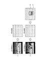
ここで、車間距離算出処理の詳細を、図5〜図7を参照して説明する。図5は、車間距離算出部103の詳細を例示するブロック図である。図6は、車間距離算出部103の処理の流れを説明する概念図である。図7、8は、視差情報I1による距離をもとにした先行車両との車間距離の算出を例示する概念図である。
Here, the details of the inter-vehicle distance calculation process will be described with reference to FIGS. FIG. 5 is a block diagram illustrating details of the inter-vehicle
図5に示すように、車間距離算出部103は、車間距離算出処理を行う機能構成として、対応路面位置算出部1031、対応路面位置集計部1032、非路面判定部1033を備え、距離算出処理によって得られた距離を示す距離情報をもとに、先行車両との車間距離を示す車間距離情報を出力する。
As shown in FIG. 5, the inter-vehicle
対応路面位置算出部1031は、ステレオカメラ21で撮像したステレオ画像において、手前から奥に向かって段階的な距離を示す路面と対応する位置の算出を行う対応路面位置算出処理(図6:S1031)を行う。
The corresponding road surface
具体的には、対応路面位置算出部1031は、図7に示すような先行車両なしの撮像条件で、ステレオカメラ21により路面を撮像して得られる距離情報(算出結果)であり、ステレオ画像に映り込む路面と、その路面及び車両V1間の距離との対応関係を示す対応路面位置情報をメモリなどに予め保持している。この対応路面位置情報は、車両V1からある距離に離れた位置にある路面が、ステレオ画像上のどの位置に対応しているかという対応関係を示している。
Specifically, the corresponding road surface
そして、対応路面位置算出部1031は、距離算出処理によって得られた距離情報を受け取ると、対応路面位置情報をもとに、距離情報に対応する路面位置を算出する。具体的には、図7に示すような先行車両ありの撮像条件の場合、距離4mの物体の領域R1は、その下方に存在するような距離4mの位置P1に対応することが算出される。
When the corresponding road surface
対応路面位置集計部1032は、路面位置に対応する領域の合計数を集計する対応路面位置集計処理(図6:S1032)を行う。ここで、路面位置に対応する領域の合計数とは、例えば位置P1に対応した領域R1の画素数(図7における「4」のカウント数)であり、領域R1の面積に対応している。具体的には、図7に示すような先行車両ありの撮像条件の場合、距離4mの位置P1に対応する領域R1の画素数を集計してその面積を求めることとなる。
The corresponding road surface
非路面判定部1033は、対応路面位置集計部1032により集計された合計数をもとに、路面の各位置において、その上方に非路面の領域が存在するか否かを判定する非路面判定処理(図6:S1033)を行う。
The non-road
図7に示すように、距離4mの位置に先行車両が存在すれば、距離4mとなる非路面の領域R1が広く存在するため、位置P1と対応する領域R1の合計数(距離4mの集計)が多くなる。一方、先行車両が存在しない段階的な距離を示す路面では、各段階の距離が個別に集計されるだけなので、距離4mの位置P1と対応する領域R1の合計数がなく、距離4mに集計が集中することはない。 As shown in FIG. 7, if there is a preceding vehicle at a distance of 4 m, a non-road surface area R1 having a distance of 4 m exists widely, so the total number of areas R1 corresponding to the position P1 (aggregation of distance of 4 m) Will increase. On the other hand, on the road surface indicating the stepped distance where there is no preceding vehicle, the distance of each step is only counted individually, so there is no total number of the region R1 corresponding to the position P1 of the distance 4m, and the distance 4m is counted. Don't concentrate.
したがって、非路面判定部1033は、各距離の合計数が予め決められた閾値よりも大きければ、すなわち位置P1と対応する非路面の領域R1の面積が広ければ、非路面の領域R1に先行車両が存在するものと判定する。車間距離算出部103は、非路面判定部1033により先行車両が存在すると判定された領域R1を集計した位置P1の距離値(図7の例では「4」)を車間距離情報として出力する。
Therefore, if the total number of each distance is larger than a predetermined threshold value, that is, if the area of the non-road surface region R1 corresponding to the position P1 is large, the non-road
上述した車両の判定にかかる閾値は、車両が存在しない路面のみを撮像して得られる距離情報(図7の先行車両なしの算出結果)を集計した値、すなわち対応路面位置情報の集計数を用いてよい。もしくは、ノイズによる誤り集計が発生することを考慮して、上述した集計数+ε(εはノイズに相当する小値)を閾値としてもよい。また、距離が遠くなるほど車両に対応した領域が小さくなることから、εを距離の遠さに応じて小さくしてもよい。 As the threshold for determining the vehicle described above, a value obtained by totaling distance information (calculation result without preceding vehicle in FIG. 7) obtained by imaging only a road surface where no vehicle exists, that is, the total number of corresponding road surface position information is used. It's okay. Alternatively, in consideration of the occurrence of error totalization due to noise, the above-mentioned total count + ε (ε is a small value corresponding to noise) may be used as a threshold value. Moreover, since the area | region corresponding to a vehicle becomes small, so that distance becomes long, you may make (epsilon) small according to the distance of distance.
また、図8に示すように、先行車両の隠れがない場合は、車間距離算出部103は、車両V2による非路面の領域R1に対応した位置P1の距離値「6」を車間距離情報として出力する。これに対し、先行車両同士で隠れがある場合は、隠される側の距離が遠い先行車両の距離情報が得られない場合がある。
As shown in FIG. 8, when there is no hiding of the preceding vehicle, the inter-vehicle
図8の例では、撮像領域Rにおいて手前に写り込んだ車両V2aについては、領域R1の集計によって存在ありと判定され、距離値を「2」とした車間距離情報が得られる。一方、撮像領域Rにおいて車両V2aに一部が隠される形で写り込んだ車両V2bについては、領域R2の集計だけでは存在ありと判定されない場合がある。このため、車両V2bの車間距離情報が得られない場合が生じる。 In the example of FIG. 8, the vehicle V2a reflected in the foreground in the imaging region R is determined to be present by aggregation of the region R1, and inter-vehicle distance information with a distance value “2” is obtained. On the other hand, in the imaging region R, the vehicle V2b that is partially hidden in the vehicle V2a may not be determined to exist only by counting the region R2. For this reason, the inter-vehicle distance information of the vehicle V2b may not be obtained.
対応路面位置集計部1032では、距離の異なる2つの非路面の領域R1、R2が隣接する場合、距離が近い非路面の領域R1にある物体で非路面の領域R1にある物体が隠されていると推定されることから、距離が近い非路面の領域R1の一部の領域R2aを、距離が遠い非路面の領域R2として距離値を置き換える。
In the corresponding road surface
具体的には、領域R2の距離値「6」の下に、路面であった場合に本来得られる距離値「8」とは異なる距離値「2」の領域R1がある場合には、対応路面位置集計部1032は、領域R2と隣接する領域R1の一部について、距離値「2」を距離値「6」と置き換えた領域R2aとする。この領域R2aの大きさは、距離値の大小に応じたものであってよく、例えば距離値が大きい、すなわち距離が遠い場合には領域R2aの大きさを小さくする。また、距離「6」が得られている領域R2に基づき、路面であった場合、すなわち車両V2aが存在しなかった場合に距離「6」が得られる領域を推定し、この推定した領域を領域R2aとしてもよい。そして、対応路面位置集計部1032は、位置P2と対応する領域R2、R2aの合計数を集計する。
Specifically, when there is an area R1 having a distance value “2” different from the distance value “8” originally obtained when the road surface is below the distance value “6” of the area R2, the corresponding road surface The
これにより、車間距離算出部103は、位置P2に車両V2bがあるものとして距離値「6」の車間距離情報を出力できる。車両V2aにより車両V2bの一部が隠されるような場合における車両V2bの検出性を高めることが可能である。
Accordingly, the inter-vehicle
図3に戻り、車両密度算出部104は、車間距離算出部103の車間距離算出処理により算出された車間距離をもとに、車両V1の現在位置における車両の密度を算出する車両密度算出処理を行う(図4:S104)。例えば、車両の密度(D)は、車間距離算出処理により車間距離D1が得られていた場合、D=1/(車間距離D1)として算出してよい。
Returning to FIG. 3, the vehicle
なお、上述した車両V2aと車両V1の車間距離(D2a)、車両V2bと車両V1の車間距離(D2b)が得られていた場合には、車両間の平均の車間距離を求めた後に車両の密度(D)を求めてもよい。具体的には、(平均の車間距離)=(D2a+(D2b−D2a)/2=D2b/2として算出してよい。 In addition, when the inter-vehicle distance (D2a) between the vehicle V2a and the vehicle V1 and the inter-vehicle distance (D2b) between the vehicle V2b and the vehicle V1 are obtained, the density of the vehicle is obtained after obtaining the average inter-vehicle distance between the vehicles. (D) may be obtained. Specifically, it may be calculated as (average inter-vehicle distance) = (D2a + (D2b−D2a) / 2 = D2b / 2.
車両位置情報取得部105は、GPS装置22からの出力をもとに、車両V1の現在位置を示す車両位置情報を取得する車両位置情報取得処理を行う(図4:S105)。
The vehicle position
道路情報算出部106は、車両位置情報取得処理で得られた車両位置情報と、車両密度算出処理で得られた車両の密度とをもとに、車両V1のある位置の現在時刻における車両密度として定義される道路情報を作成する道路情報作成処理を行う(図4:S106)。この際に、道路情報算出部106は、異なる時刻間の車両V1の車両位置情報の変化をもとに、車両V1の走行速度を算出し、その走行速度を道路情報に含めてもよい。この道路情報作成処理で得られた道路情報は、制御部23の制御のもと、通信部24により管理装置10へ送信される。
The road
道路情報集積部107は、車載端末20より送信された道路情報をもとに、車両V1が走行した経路における道路情報を集計し、その経路の混雑具合を示す道路状況を算出する道路情報集積処理を行う(図4:S107)。管理装置10では、道路情報集積処理によって車載端末20を搭載した各車両が走行した経路における道路状況G1、G2、G3を求め、渋滞の発生場所などを示す地図情報M1としてディスプレイに表示してオペレータに通知することで、交通管制、渋滞情報の提供、バスの運行管理などの各種サービスに利用できる。
The road
以上のように、道路状況把握システム1では、車載端末20のステレオカメラ21により撮像されたステレオ画像をもとに、車両V1の進行方向に沿った車両V2との車間距離を算出し、その車間距離をもとに、GPS装置22により検出された車両V1の位置における車両の密度を算出する。そして、車載端末20は車両V1の位置と、車両の密度とを含む道路情報を管理装置10へ送信し、管理装置10では、車両V1が走行した経路における道路情報を集計して、その経路の混雑具合を示す道路状況を算出する。
As described above, the road
したがって、道路状況把握システム1では、車両V1が走行する経路に沿って路側装置を設置するなどのコストを抑えることができる。また、道路状況把握システム1では、車線を走行する車両の速度と位置だけで道路状況を把握するのではなく、ステレオ画像による車間距離をもとに車両の密度を求めることから、車両が過密な状態であるか否かなどの、より正確な道路状況を把握することが可能である。
Therefore, in the road
なお、道路状況把握システム1の管理装置10、車載端末20が備える機能構成は、一例であり、上述したものに限定しない。例えば、車載端末20は、ステレオ撮像部101、車両位置情報取得部105のみを備え、ステレオ撮像部101により撮像されたステレオ画像と、車両位置情報取得部105により取得された車両V1の現在位置とを管理装置10へ通知し、管理装置10側は、距離算出部102、車間距離算出部103、車両密度算出部104、道路情報算出部106、道路情報集積部107を備える構成であってもよい。
In addition, the function structure with which the
また、車載端末20がステレオ撮像部101、距離算出部102、車間距離算出部103、車両密度算出部104、車両位置情報取得部105、道路情報算出部106、道路情報集積部107の全てを備えてもよい。この場合は、車載端末20により得られた、車両V1が走行する経路についての道路状況の履歴を、HDD(Hard Disk Drive)レコーダーなどの記憶装置(図示しない)に蓄積する。そして、車両V1に搭載されたナビゲーション装置(図示しない)は、所定の地点間の経路を算出する際に、記憶装置に蓄積された道路状況の履歴を参照することで、より混雑の少ない経路を案内できる。
The in-
(変形例1)
図9は、変形例1にかかる道路状況把握システム1aの機能構成の一例を示すブロック図である。図9に示すように、変形例1では、管理装置10の制御部14により実現される配車制御部108を更に備えている点が上述した第1の実施形態とは異なる。
(Modification 1)
FIG. 9 is a block diagram illustrating an example of a functional configuration of the road
配車制御部108は、道路情報集積部107により算出された道路状況を、所定のエリアを走行するバス・タクシー、集配車、乗用車などの車両に配信する配車制御を行う。ここでいう、所定のエリアとは、通信ネットワークNを介して車両V1に配信可能なエリアであればよく、例えば運行指令所が管轄するエリアであってよい。
The vehicle
配車制御部108は、道路情報集積部107により算出された道路状況に基づいて、例えば渋滞が発生しているエリアを示す情報を、通信ネットワークNを介して車両に配信する。したがって、バス・タクシー、集配車、乗用車などの車両側では、配信された情報をもとに、例えばナビゲーション装置が所定の地点間の経路を算出する際に、渋滞が発生しているエリアを回避する経路を選択することで、効率的な走行を実現することができる。
Based on the road condition calculated by the road
(変形例2)
図10は、変形例2にかかる道路状況把握システム1bの機能構成の一例を示すブロック図である。図11は、変形例2にかかる道路状況把握システムの処理の流れを説明する概念図である。図12は、車線毎の車間距離の算出を例示する概念図である。
(Modification 2)
FIG. 10 is a block diagram illustrating an example of a functional configuration of the road condition grasping system 1b according to the second modification. FIG. 11 is a conceptual diagram illustrating the processing flow of the road condition grasping system according to the second modification. FIG. 12 is a conceptual diagram illustrating the calculation of the inter-vehicle distance for each lane.
図10に示すように、変形例2では、車載端末20の制御部23により実現される車線判別部109を更に備えている点が上述した第1の実施形態とは異なる。
As shown in FIG. 10,
車線判別部109は、ステレオカメラ21により撮像された画像をもとに、画像処理を行って車線を判別する車線判別処理を行う(図11:S109)。具体的には、車線判別部109は、ステレオカメラ21により撮像された画像から車線の区切りを示す白線L1、L2を検出することによって、車線(走行エリア)を判別する。この車線判別処理には、例えば「"Video Based Lane Estimation and Tracking for Driver Assistance:Survey, System, and Evaluation", Joel C. McCall et al., IEEE Transactions on ITS, March 2006」のような公知の手法を用いればよい。
The
車間距離算出部103は、車線判別部109により判別された車線ごとに、車両V1の進行方向に沿った前方にある車両V2との車間距離D1を算出する車間距離算出処理を行う(図4:S103)。具体的には、車両V1が白線L1、L2の間の車線を走行している場合には、同じ車線を走行している車両V2の車間距離D1を算出する(図11参照)。
The inter-vehicle
また、図12に示すように、白線L1の左側車線に車両V21と車両V22とが走行し、白線L2の右側車線に車両V23が走行している場合には、白線L1の左側車線と白線L2の右側車線とで車間距離(DL、DR)を算出する。具体的には、車両V1と、車両V21、V22、V23との車間距離がそれぞれD21、D22、D23であるものとする。 Also, as shown in FIG. 12, when the vehicle V21 and the vehicle V22 are traveling in the left lane of the white line L1, and the vehicle V23 is traveling in the right lane of the white line L2, the left lane and the white line L2 of the white line L1. The inter-vehicle distance (DL, DR) is calculated from the right lane. Specifically, the inter-vehicle distances between the vehicle V1 and the vehicles V21, V22, and V23 are D21, D22, and D23, respectively.
白線L1の左側車線のように、複数台の車両の車間距離が得られた車線の車間距離DLは、DL=D22−D21として算出する。もしくは、車両の長さをCとした場合、DL=D22−D21−Cと算出してもよい。 Like the left lane of the white line L1, the inter-vehicle distance DL of the lane from which the inter-vehicle distance of a plurality of vehicles is obtained is calculated as DL = D22-D21. Alternatively, when the length of the vehicle is C, DL = D22−D21−C may be calculated.
一方、白線L2の右側車線のように1台の車両の車間距離しか得られていない場合には、車線における真の車間距離を算出できないことから、DR=D23とする。すなわち、近似値として車両V1との車間距離D23を白線L2の右側車線の車間距離とする。 On the other hand, when only the inter-vehicle distance of one vehicle is obtained as in the right lane of the white line L2, the true inter-vehicle distance in the lane cannot be calculated, so DR = D23. That is, the inter-vehicle distance D23 from the vehicle V1 is set as the inter-vehicle distance of the right lane of the white line L2 as an approximate value.
以上のように、変形例2では、車線ごとの車間距離が得られることから、より精度の高い道路状況を把握することが可能となる。 As described above, in the second modification, since the inter-vehicle distance for each lane can be obtained, it is possible to grasp the road condition with higher accuracy.
(変形例3)
図13は、変形例3にかかる道路状況把握システム1cの機能構成の一例を示すブロック図である。図14は、変形例3にかかる道路状況把握システム1cの処理の流れを説明する概念図である。
(Modification 3)
FIG. 13 is a block diagram illustrating an example of a functional configuration of a road
図13に示すように、変形例3では、車載端末20の制御部23により実現される車両速度算出部110を更に備えている点が上述した変形例2とは異なる。車両V1の走行速度を求めて道路情報に含める構成を前述したが、車両V1とは異なる車線の走行速度については求めることができない。そこで、変形例3では、車両V1が走行する車線とは異なる他の車線の走行速度を算出するための車両速度算出部110を備えている。
As shown in FIG. 13, Modification 3 is different from
車両速度算出部110は、車線判別部109により判別された車線と、車間距離算出部103により算出された車間距離と、自車である車両V1の走行速度とをもとに、車両V1と異なる車線を走行する車両の走行速度を算出する車両速度算出処理を行う(図14:S110)。これにより、道路情報算出部106は、前述した自車の走行速度と、車両速度算出部110により算出された自車と異なる車線を走行する車両の走行速度を含めた道路情報を作成することができる。
The vehicle
具体的には、車両速度算出部110は、次のようにして車両V1と異なる車線を走行する車両の走行速度を算出する。ここで、車間距離算出部103によって、ある時刻T1において他の車線を走行する車両(X)と車両V1との車間距離D(X,T1)と、時刻T2における車両(X)と車両V1との車間距離D(X,T2)とが算出されているものとする。また、時刻T1と時刻T2との時間間隔を充分短くすることで、車両(X)は同じ車両を追跡できているものとする。
Specifically, the vehicle
車両V1に対する車両(X)の相対速度V_X_relativeは、V_X_relative={D(X,T2)−D(X,T1)}/(T2−T1)として算出できる。 The relative speed V_X_relative of the vehicle (X) with respect to the vehicle V1 can be calculated as V_X_relative = {D (X, T2) −D (X, T1)} / (T2−T1).
ここで、前述した車両V1の走行速度をVとすると、車両(X)の絶対速度V_X、すなわち求めるべき走行速度は、V_X=V+V_X_relativeとして算出できる。 Here, if the travel speed of the vehicle V1 is V, the absolute speed V_X of the vehicle (X), that is, the travel speed to be obtained can be calculated as V_X = V + V_X_relative.
(第2の実施形態)
図15は、第2の実施形態にかかる道路状況把握システム1dの概要を示す概念図である。図15に示すように、道路状況把握システム1dは、単眼のデジタルカメラであるカメラ21dで周囲を撮像する車載端末20dを車両V1に搭載する点が第1の実施形態とは異なっている。
(Second Embodiment)
FIG. 15 is a conceptual diagram showing an outline of a road
図16は、第2の実施形態にかかる道路状況把握システム1dの機能構成の一例を示すブロック図である。図17は、第2の実施形態にかかる道路状況把握システム1dの処理の流れを説明する概念図である。図18は、撮像画像から検出された車両の位置をもとにした車間距離の算出を例示する概念図である。
FIG. 16 is a block diagram illustrating an example of a functional configuration of a road
図16に示すように、道路状況把握システム1dは、前述したステレオ撮像部101、距離算出部102、車間距離算出部103に代わって、車載端末20dの制御部23により実現される撮像部111、車両検出部112、車間距離算出部113を備えている。
As shown in FIG. 16, the road
撮像部111は、カメラ21dで撮像した撮像画像を取得する撮像処理(図17:S111)を行う。車両検出部112は、撮像処理によって得られた撮像画像G10をもとに、その撮像画像G10に映り込む車両を検出する車両検出処理を行う(図17:S112)。この車両検出処理には、例えば「"A Trainable System for Object Detection", Papageorgiou et al., IJCV-2000」のような公知の車両検出技術を用いればよい。この車両検出処理によって撮像画像G10に映り込む車両に対応した領域R10が得られる。
The
車間距離算出部113は、車両検出処理の検出結果をもとに、撮像画像G10内における車両の位置に基づいて、その車両との車間距離を算出する車間距離算出処理を行う(図17:S113)。具体的には、車間距離算出部113は、ROMなどのメモリ上に、図18に示すような検出位置・距離変換情報T1を保持している。検出位置・距離変換情報T1は、カメラ21dの撮像画像G10内の位置(画素)ごとの車間距離がマトリクス状に示されたデータであってよい。車間距離算出部113は、検出位置・距離変換情報T1を参照することで、撮像画像G10に映り込む車両の領域R10が接地する位置P1をもとに、車両との車間距離を得ることができる。
Based on the detection result of the vehicle detection process, the inter-vehicle
上述したように、単眼のカメラ21dで周囲を撮像する車載端末20dを車両V1に搭載する構成であっても車間距離を求めることができ、その車間距離をもとに車両の密度を求めることから、車両が過密な状態であるか否かなどの、より正確な道路状況を把握することが可能である。
As described above, even if the vehicle-mounted terminal 20d that captures the surroundings with the
なお、本発明は、上記実施形態そのままに限定されるものではなく、実施段階ではその要旨を逸脱しない範囲で構成要素を変形して具体化することができる。また、上記実施形態に開示されている複数の構成要素の適宜な組み合わせにより、種々の発明を形成することができる。例えば、実施形態に示される全構成要素からいくつかの構成要素を削除してもよい。さらに、異なる実施形態にわたる構成要素を適宜組み合わせても良い。 Note that the present invention is not limited to the above-described embodiment as it is, and can be embodied by modifying the constituent elements without departing from the scope of the invention in the implementation stage. Moreover, various inventions can be formed by appropriately combining a plurality of constituent elements disclosed in the embodiment. For example, some components may be deleted from all the components shown in the embodiment. Furthermore, the constituent elements over different embodiments may be appropriately combined.
1、1a、1b、1c、1d…道路状況把握システム、10…管理装置、11…表示部、12…入力部、13…通信部、14…制御部、20、20d…車載端末、21…ステレオカメラ、21d…カメラ、22…GPS装置、23…制御部、24…通信部、25…入力部、26…表示部、101…ステレオ撮像部、102…距離算出部、103、113…車間距離算出部、104…車両密度算出部、105…車両位置情報取得部、106…道路情報算出部、107…道路情報集積部、108…配車制御部、109…車線判別部、110…車両速度算出部、111…撮像部、112…車両検出部、1031…対応路面位置算出部、1032…対応路面位置集計部、1033…非路面判定部、D1、D21、D22、D23…車間距離、G1、G2、G3…道路状況、G10…撮像画像、I1…視差情報、L1、L2…白線、M1…地図情報、N…通信ネットワーク、P1、P2…位置、R…撮像領域、R1、R2、R2a、R10…領域、T1…検出位置・距離変換情報、V1、V2、V2a、V2b、V21〜V23…車両
DESCRIPTION OF
Claims (7)
前記車載装置は、
前記車両の位置を検出する位置検出手段と、
前記車両の周囲を撮像する撮像手段と、
前記撮像手段により撮像された画像をもとに、他の車両との車間距離を算出する車間距離算出手段と、
前記算出された車間距離と、前記検出された車両の位置とに基づいて、当該位置を走行する車両の密度を算出する車両密度算出手段と、
前記検出された車両の位置と、前記算出された車両の密度とを含む道路情報を前記情報処理装置へ送信する送信手段と、を備え、
前記情報処理装置は、
前記送信された道路情報をもとに、前記車両が走行した経路における道路情報を集計して前記経路の混雑具合を示す道路状況を算出する道路状況算出手段を備える、
道路状況把握システム。 A road condition grasping system comprising an in-vehicle device mounted on a vehicle and an information processing device that processes information transmitted from the in-vehicle device,
The in-vehicle device is
Position detecting means for detecting the position of the vehicle;
Imaging means for imaging the periphery of the vehicle;
An inter-vehicle distance calculating means for calculating an inter-vehicle distance from another vehicle based on the image captured by the imaging means;
Vehicle density calculation means for calculating the density of a vehicle traveling at the position based on the calculated inter-vehicle distance and the detected position of the vehicle;
Transmission means for transmitting road information including the detected position of the vehicle and the calculated density of the vehicle to the information processing apparatus,
The information processing apparatus includes:
Based on the transmitted road information, comprising road condition calculation means for calculating road conditions indicating the degree of congestion of the route by aggregating road information on the route traveled by the vehicle,
Road condition grasping system.
請求項1に記載の道路状況把握システム。 The inter-vehicle distance calculating means determines the non-road surface area when the non-road surface area different from the road surface indicating a stepwise distance in the captured image is a predetermined area with a predetermined width. Detecting as a vehicle region, and calculating the inter-vehicle distance based on the detected other vehicle region;
The road condition grasping system according to claim 1.
請求項2に記載の道路状況把握システム。 The inter-vehicle distance calculating means detects a region of the other vehicle by setting a part of the non-road surface area with a short distance as a non-road surface area with a long distance when two non-road surface areas with different distances are adjacent to each other. Do,
The road condition grasping system according to claim 2.
前記撮像された画像をもとに、前記車両が走行する車線を検出する車線検出手段を更に備え、
前記車間距離算出手段は、前記検出された車線ごとの前記車間距離を算出する、
請求項1乃至3のいずれか一項に記載の道路状況把握システム。 The in-vehicle device is
Further comprising lane detection means for detecting a lane in which the vehicle travels based on the captured image;
The inter-vehicle distance calculating means calculates the inter-vehicle distance for each detected lane.
The road condition grasping system according to any one of claims 1 to 3.
前記撮像された画像に含まれる車両を検出する車両検出手段を更に備え、
前記車間距離算出手段は、前記撮像された画像内における前記検出された車両の位置に基づいて前記車間距離を算出する、
請求項1に記載の道路状況把握システム。 The in-vehicle device is
Vehicle detection means for detecting a vehicle included in the captured image;
The inter-vehicle distance calculating means calculates the inter-vehicle distance based on the detected position of the vehicle in the captured image.
The road condition grasping system according to claim 1.
前記算出された道路状況を、所定のエリアを走行する車両に配信する配信手段を更に備える、
請求項1乃至5のいずれか一項に記載の道路状況把握システム。 The information processing apparatus includes:
A distribution means for distributing the calculated road condition to a vehicle traveling in a predetermined area;
The road condition grasping system according to any one of claims 1 to 5.
前記車両の位置を検出する位置検出手段と、
前記撮像手段により撮像された画像をもとに、他の車両との車間距離を算出する車間距離算出手段と、
前記算出された車間距離と、前記検出された車両の位置とに基づいて、当該位置を走行する車両の密度を算出する車両密度算出手段と、
前記検出された車両の位置に基づいた前記車両が走行した経路における、前記算出された車両の密度を集計して、前記経路の混雑具合を示す道路状況を算出する道路状況算出手段と、
を備える道路状況把握装置。 Imaging means for imaging the surroundings of the vehicle;
Position detecting means for detecting the position of the vehicle;
An inter-vehicle distance calculating means for calculating an inter-vehicle distance from another vehicle based on the image captured by the imaging means;
Vehicle density calculation means for calculating the density of a vehicle traveling at the position based on the calculated inter-vehicle distance and the detected position of the vehicle;
Road condition calculation means for calculating the road condition indicating the degree of congestion of the route by aggregating the calculated density of the vehicle in the route traveled by the vehicle based on the position of the detected vehicle;
A road condition grasping device.
Priority Applications (3)
| Application Number | Priority Date | Filing Date | Title |
|---|---|---|---|
| JP2013132950A JP6173791B2 (en) | 2013-06-25 | 2013-06-25 | Road condition grasping system and road condition grasping device |
| PCT/JP2014/065934 WO2014208388A1 (en) | 2013-06-25 | 2014-06-16 | System for gauging road conditions, and device for gauging road conditions |
| CN201480036002.4A CN105339992B (en) | 2013-06-25 | 2014-06-16 | Condition of road surface grasps system and condition of road surface grasps device |
Applications Claiming Priority (1)
| Application Number | Priority Date | Filing Date | Title |
|---|---|---|---|
| JP2013132950A JP6173791B2 (en) | 2013-06-25 | 2013-06-25 | Road condition grasping system and road condition grasping device |
Publications (2)
| Publication Number | Publication Date |
|---|---|
| JP2015007902A true JP2015007902A (en) | 2015-01-15 |
| JP6173791B2 JP6173791B2 (en) | 2017-08-02 |
Family
ID=52141730
Family Applications (1)
| Application Number | Title | Priority Date | Filing Date |
|---|---|---|---|
| JP2013132950A Active JP6173791B2 (en) | 2013-06-25 | 2013-06-25 | Road condition grasping system and road condition grasping device |
Country Status (3)
| Country | Link |
|---|---|
| JP (1) | JP6173791B2 (en) |
| CN (1) | CN105339992B (en) |
| WO (1) | WO2014208388A1 (en) |
Cited By (5)
| Publication number | Priority date | Publication date | Assignee | Title |
|---|---|---|---|---|
| CN105741545A (en) * | 2016-03-16 | 2016-07-06 | 山东大学 | Traffic state judgment device based on bus GNSS space-time trajectory data and method thereof |
| JP2017068688A (en) * | 2015-09-30 | 2017-04-06 | 株式会社東芝 | Inter-vehicle distance detection device, inter-vehicle distance detection method, and program |
| JP2017194913A (en) * | 2016-04-22 | 2017-10-26 | 株式会社東芝 | Probe information processing server, probe vehicle, and probe information processing method |
| JP2021135692A (en) * | 2020-02-26 | 2021-09-13 | トヨタ自動車株式会社 | Server, vehicle allocation method, vehicle allocation program, and vehicle allocation system |
| JP2022050311A (en) * | 2020-12-21 | 2022-03-30 | ペキン バイドゥ ネットコム サイエンス アンド テクノロジー カンパニー リミテッド | Method for detecting lane change of vehicle, system, electronic apparatus, storage medium, roadside machine, cloud control platform, and computer program |
Families Citing this family (12)
| Publication number | Priority date | Publication date | Assignee | Title |
|---|---|---|---|---|
| CN105241468A (en) * | 2015-10-28 | 2016-01-13 | 东华大学 | Vehicle route real-time selection system based on vehicle self-organizing network |
| CN107578632A (en) * | 2016-07-05 | 2018-01-12 | 奥迪股份公司 | Traffic density detecting system, the vehicles and method |
| JP6686760B2 (en) * | 2016-07-21 | 2020-04-22 | いすゞ自動車株式会社 | Image processing apparatus and image processing method |
| JP6662284B2 (en) * | 2016-12-22 | 2020-03-11 | 株式会社オートネットワーク技術研究所 | Driving support system and driving support device |
| JP6965735B2 (en) * | 2017-12-26 | 2021-11-10 | トヨタ自動車株式会社 | Information processing equipment, in-vehicle equipment and information processing methods |
| CN108428356B (en) * | 2018-03-21 | 2020-06-02 | 东南大学 | Road condition map display and driving assistance application method based on fluid density field |
| US11443619B2 (en) | 2018-05-15 | 2022-09-13 | Kabushiki Kaisha Toshiba | Vehicle recognition apparatus and vehicle recognition method |
| CN108922242A (en) * | 2018-06-05 | 2018-11-30 | 宁波金洋化工物流有限公司 | The preventative tracking of harmful influence haulage vehicle and control platform |
| JP7082538B2 (en) * | 2018-07-10 | 2022-06-08 | 本田技研工業株式会社 | Image processing equipment and programs |
| CN109410582B (en) * | 2018-11-27 | 2021-11-16 | 易念科技(深圳)有限公司 | Traffic condition analysis method and terminal equipment |
| JP2020094959A (en) * | 2018-12-14 | 2020-06-18 | ヤフー株式会社 | Route search device, method for searching for route, and route search program |
| CN109615874B (en) * | 2018-12-28 | 2021-02-02 | 浙江大学 | Road condition analysis method based on form tower psychological criterion |
Citations (4)
| Publication number | Priority date | Publication date | Assignee | Title |
|---|---|---|---|---|
| JP2006059188A (en) * | 2004-08-20 | 2006-03-02 | Matsushita Electric Ind Co Ltd | Traffic information system and information analyzer |
| JP2008015847A (en) * | 2006-07-07 | 2008-01-24 | Hitachi Ltd | Traffic information system |
| JP2012118916A (en) * | 2010-12-03 | 2012-06-21 | Fujitsu Ltd | Lane change diagnostic device, lane change diagnostic method and lane change diagnostic program |
| JP2013109457A (en) * | 2011-11-18 | 2013-06-06 | Fuji Heavy Ind Ltd | Device and method for recognizing vehicle exterior environment |
Family Cites Families (2)
| Publication number | Priority date | Publication date | Assignee | Title |
|---|---|---|---|---|
| CN101710448B (en) * | 2009-12-29 | 2011-08-10 | 浙江工业大学 | Road traffic state detecting device based on omnibearing computer vision |
| CN102081842B (en) * | 2010-11-03 | 2013-02-20 | 北京世纪高通科技有限公司 | Method and device for evaluating video data source |
-
2013
- 2013-06-25 JP JP2013132950A patent/JP6173791B2/en active Active
-
2014
- 2014-06-16 WO PCT/JP2014/065934 patent/WO2014208388A1/en active Application Filing
- 2014-06-16 CN CN201480036002.4A patent/CN105339992B/en active Active
Patent Citations (4)
| Publication number | Priority date | Publication date | Assignee | Title |
|---|---|---|---|---|
| JP2006059188A (en) * | 2004-08-20 | 2006-03-02 | Matsushita Electric Ind Co Ltd | Traffic information system and information analyzer |
| JP2008015847A (en) * | 2006-07-07 | 2008-01-24 | Hitachi Ltd | Traffic information system |
| JP2012118916A (en) * | 2010-12-03 | 2012-06-21 | Fujitsu Ltd | Lane change diagnostic device, lane change diagnostic method and lane change diagnostic program |
| JP2013109457A (en) * | 2011-11-18 | 2013-06-06 | Fuji Heavy Ind Ltd | Device and method for recognizing vehicle exterior environment |
Cited By (5)
| Publication number | Priority date | Publication date | Assignee | Title |
|---|---|---|---|---|
| JP2017068688A (en) * | 2015-09-30 | 2017-04-06 | 株式会社東芝 | Inter-vehicle distance detection device, inter-vehicle distance detection method, and program |
| CN105741545A (en) * | 2016-03-16 | 2016-07-06 | 山东大学 | Traffic state judgment device based on bus GNSS space-time trajectory data and method thereof |
| JP2017194913A (en) * | 2016-04-22 | 2017-10-26 | 株式会社東芝 | Probe information processing server, probe vehicle, and probe information processing method |
| JP2021135692A (en) * | 2020-02-26 | 2021-09-13 | トヨタ自動車株式会社 | Server, vehicle allocation method, vehicle allocation program, and vehicle allocation system |
| JP2022050311A (en) * | 2020-12-21 | 2022-03-30 | ペキン バイドゥ ネットコム サイエンス アンド テクノロジー カンパニー リミテッド | Method for detecting lane change of vehicle, system, electronic apparatus, storage medium, roadside machine, cloud control platform, and computer program |
Also Published As
| Publication number | Publication date |
|---|---|
| CN105339992B (en) | 2017-06-23 |
| CN105339992A (en) | 2016-02-17 |
| JP6173791B2 (en) | 2017-08-02 |
| WO2014208388A1 (en) | 2014-12-31 |
Similar Documents
| Publication | Publication Date | Title |
|---|---|---|
| JP6173791B2 (en) | Road condition grasping system and road condition grasping device | |
| US11984030B2 (en) | Vehicular information systems and methods | |
| US10832575B2 (en) | Network connected parking system | |
| EP3078937B1 (en) | Vehicle position estimation system, device, method, and camera device | |
| CN102889892B (en) | The method of real scene navigation and navigation terminal | |
| US9727820B2 (en) | Vehicle behavior prediction device and vehicle behavior prediction method, and driving assistance device | |
| US20210341303A1 (en) | Clustering event information for vehicle navigation | |
| US20170248962A1 (en) | Method and device for localizing a vehicle in its surroundings | |
| US10369995B2 (en) | Information processing device, information processing method, control device for vehicle, and control method for vehicle | |
| US20140067434A1 (en) | Methods and Systems for Providing Risk Profile Analytics | |
| US20120035848A1 (en) | Route search device, route search method, and computer program | |
| JP2019032174A (en) | Information processing system and information processing method | |
| US11332159B2 (en) | Method for providing transportation service using autonomous vehicle | |
| US11636756B2 (en) | Multi-modal traffic detection | |
| US10460185B2 (en) | Roadside image tracking system | |
| JP5907249B2 (en) | Unexpected prediction sensitivity judgment device | |
| CN108016445B (en) | System and method for vehicular application of traffic flow | |
| JP7362733B2 (en) | Automated crowdsourcing of road environment information | |
| CN112805762B (en) | System and method for improving traffic condition visualization | |
| CN112305499B (en) | Method and device for positioning according to light source | |
| CN113799782A (en) | Vehicle control device and vehicle control method | |
| CN115359671A (en) | Intersection vehicle cooperative control method and related equipment | |
| US11823570B2 (en) | Traffic management server, and method and computer program for traffic management using the same | |
| JP7468633B2 (en) | State estimation method, state estimation device, and program | |
| US20240054888A1 (en) | Information provision system, method for providing passenger vehicle information, and recorded program medium |
Legal Events
| Date | Code | Title | Description |
|---|---|---|---|
| RD01 | Notification of change of attorney |
Free format text: JAPANESE INTERMEDIATE CODE: A7421 Effective date: 20151102 |
|
| A621 | Written request for application examination |
Free format text: JAPANESE INTERMEDIATE CODE: A621 Effective date: 20160304 |
|
| A131 | Notification of reasons for refusal |
Free format text: JAPANESE INTERMEDIATE CODE: A131 Effective date: 20170110 |
|
| A521 | Written amendment |
Free format text: JAPANESE INTERMEDIATE CODE: A523 Effective date: 20170308 |
|
| TRDD | Decision of grant or rejection written | ||
| A01 | Written decision to grant a patent or to grant a registration (utility model) |
Free format text: JAPANESE INTERMEDIATE CODE: A01 Effective date: 20170606 |
|
| A61 | First payment of annual fees (during grant procedure) |
Free format text: JAPANESE INTERMEDIATE CODE: A61 Effective date: 20170705 |
|
| R151 | Written notification of patent or utility model registration |
Ref document number: 6173791 Country of ref document: JP Free format text: JAPANESE INTERMEDIATE CODE: R151 |